EP4000907A1 - Tire mold, production method for tire, and tire - Google Patents
Tire mold, production method for tire, and tire Download PDFInfo
- Publication number
- EP4000907A1 EP4000907A1 EP21205545.3A EP21205545A EP4000907A1 EP 4000907 A1 EP4000907 A1 EP 4000907A1 EP 21205545 A EP21205545 A EP 21205545A EP 4000907 A1 EP4000907 A1 EP 4000907A1
- Authority
- EP
- European Patent Office
- Prior art keywords
- point
- shoulder
- intersection
- forming
- land
- Prior art date
- Legal status (The legal status is an assumption and is not a legal conclusion. Google has not performed a legal analysis and makes no representation as to the accuracy of the status listed.)
- Granted
Links
Images




Classifications
-
- B—PERFORMING OPERATIONS; TRANSPORTING
- B29—WORKING OF PLASTICS; WORKING OF SUBSTANCES IN A PLASTIC STATE IN GENERAL
- B29D—PRODUCING PARTICULAR ARTICLES FROM PLASTICS OR FROM SUBSTANCES IN A PLASTIC STATE
- B29D30/00—Producing pneumatic or solid tyres or parts thereof
- B29D30/06—Pneumatic tyres or parts thereof (e.g. produced by casting, moulding, compression moulding, injection moulding, centrifugal casting)
- B29D30/0601—Vulcanising tyres; Vulcanising presses for tyres
- B29D30/0606—Vulcanising moulds not integral with vulcanising presses
-
- B—PERFORMING OPERATIONS; TRANSPORTING
- B29—WORKING OF PLASTICS; WORKING OF SUBSTANCES IN A PLASTIC STATE IN GENERAL
- B29D—PRODUCING PARTICULAR ARTICLES FROM PLASTICS OR FROM SUBSTANCES IN A PLASTIC STATE
- B29D30/00—Producing pneumatic or solid tyres or parts thereof
- B29D30/0005—Pretreatment of tyres or parts thereof, e.g. preheating, irradiation, precuring
-
- B—PERFORMING OPERATIONS; TRANSPORTING
- B29—WORKING OF PLASTICS; WORKING OF SUBSTANCES IN A PLASTIC STATE IN GENERAL
- B29D—PRODUCING PARTICULAR ARTICLES FROM PLASTICS OR FROM SUBSTANCES IN A PLASTIC STATE
- B29D30/00—Producing pneumatic or solid tyres or parts thereof
- B29D30/06—Pneumatic tyres or parts thereof (e.g. produced by casting, moulding, compression moulding, injection moulding, centrifugal casting)
- B29D30/08—Building tyres
- B29D30/10—Building tyres on round cores, i.e. the shape of the core is approximately identical with the shape of the completed tyre
-
- B—PERFORMING OPERATIONS; TRANSPORTING
- B29—WORKING OF PLASTICS; WORKING OF SUBSTANCES IN A PLASTIC STATE IN GENERAL
- B29D—PRODUCING PARTICULAR ARTICLES FROM PLASTICS OR FROM SUBSTANCES IN A PLASTIC STATE
- B29D30/00—Producing pneumatic or solid tyres or parts thereof
- B29D30/06—Pneumatic tyres or parts thereof (e.g. produced by casting, moulding, compression moulding, injection moulding, centrifugal casting)
- B29D30/08—Building tyres
- B29D30/20—Building tyres by the flat-tyre method, i.e. building on cylindrical drums
-
- B—PERFORMING OPERATIONS; TRANSPORTING
- B29—WORKING OF PLASTICS; WORKING OF SUBSTANCES IN A PLASTIC STATE IN GENERAL
- B29D—PRODUCING PARTICULAR ARTICLES FROM PLASTICS OR FROM SUBSTANCES IN A PLASTIC STATE
- B29D30/00—Producing pneumatic or solid tyres or parts thereof
- B29D30/06—Pneumatic tyres or parts thereof (e.g. produced by casting, moulding, compression moulding, injection moulding, centrifugal casting)
- B29D30/08—Building tyres
- B29D30/20—Building tyres by the flat-tyre method, i.e. building on cylindrical drums
- B29D30/24—Drums
-
- B—PERFORMING OPERATIONS; TRANSPORTING
- B29—WORKING OF PLASTICS; WORKING OF SUBSTANCES IN A PLASTIC STATE IN GENERAL
- B29D—PRODUCING PARTICULAR ARTICLES FROM PLASTICS OR FROM SUBSTANCES IN A PLASTIC STATE
- B29D30/00—Producing pneumatic or solid tyres or parts thereof
- B29D30/06—Pneumatic tyres or parts thereof (e.g. produced by casting, moulding, compression moulding, injection moulding, centrifugal casting)
- B29D30/08—Building tyres
- B29D30/20—Building tyres by the flat-tyre method, i.e. building on cylindrical drums
- B29D30/24—Drums
- B29D30/26—Accessories or details, e.g. membranes, transfer rings
-
- B—PERFORMING OPERATIONS; TRANSPORTING
- B29—WORKING OF PLASTICS; WORKING OF SUBSTANCES IN A PLASTIC STATE IN GENERAL
- B29D—PRODUCING PARTICULAR ARTICLES FROM PLASTICS OR FROM SUBSTANCES IN A PLASTIC STATE
- B29D30/00—Producing pneumatic or solid tyres or parts thereof
- B29D30/06—Pneumatic tyres or parts thereof (e.g. produced by casting, moulding, compression moulding, injection moulding, centrifugal casting)
- B29D30/52—Unvulcanised treads, e.g. on used tyres; Retreading
-
- B—PERFORMING OPERATIONS; TRANSPORTING
- B60—VEHICLES IN GENERAL
- B60C—VEHICLE TYRES; TYRE INFLATION; TYRE CHANGING; CONNECTING VALVES TO INFLATABLE ELASTIC BODIES IN GENERAL; DEVICES OR ARRANGEMENTS RELATED TO TYRES
- B60C11/00—Tyre tread bands; Tread patterns; Anti-skid inserts
- B60C11/0041—Tyre tread bands; Tread patterns; Anti-skid inserts comprising different tread rubber layers
-
- B—PERFORMING OPERATIONS; TRANSPORTING
- B60—VEHICLES IN GENERAL
- B60C—VEHICLE TYRES; TYRE INFLATION; TYRE CHANGING; CONNECTING VALVES TO INFLATABLE ELASTIC BODIES IN GENERAL; DEVICES OR ARRANGEMENTS RELATED TO TYRES
- B60C11/00—Tyre tread bands; Tread patterns; Anti-skid inserts
- B60C11/0083—Tyre tread bands; Tread patterns; Anti-skid inserts characterised by the curvature of the tyre tread
-
- B—PERFORMING OPERATIONS; TRANSPORTING
- B60—VEHICLES IN GENERAL
- B60C—VEHICLE TYRES; TYRE INFLATION; TYRE CHANGING; CONNECTING VALVES TO INFLATABLE ELASTIC BODIES IN GENERAL; DEVICES OR ARRANGEMENTS RELATED TO TYRES
- B60C11/00—Tyre tread bands; Tread patterns; Anti-skid inserts
- B60C11/03—Tread patterns
- B60C11/0327—Tread patterns characterised by special properties of the tread pattern
- B60C11/0332—Tread patterns characterised by special properties of the tread pattern by the footprint-ground contacting area of the tyre tread
-
- B—PERFORMING OPERATIONS; TRANSPORTING
- B60—VEHICLES IN GENERAL
- B60C—VEHICLE TYRES; TYRE INFLATION; TYRE CHANGING; CONNECTING VALVES TO INFLATABLE ELASTIC BODIES IN GENERAL; DEVICES OR ARRANGEMENTS RELATED TO TYRES
- B60C11/00—Tyre tread bands; Tread patterns; Anti-skid inserts
- B60C11/03—Tread patterns
- B60C11/13—Tread patterns characterised by the groove cross-section, e.g. for buttressing or preventing stone-trapping
-
- B—PERFORMING OPERATIONS; TRANSPORTING
- B60—VEHICLES IN GENERAL
- B60C—VEHICLE TYRES; TYRE INFLATION; TYRE CHANGING; CONNECTING VALVES TO INFLATABLE ELASTIC BODIES IN GENERAL; DEVICES OR ARRANGEMENTS RELATED TO TYRES
- B60C11/00—Tyre tread bands; Tread patterns; Anti-skid inserts
- B60C11/03—Tread patterns
- B60C11/13—Tread patterns characterised by the groove cross-section, e.g. for buttressing or preventing stone-trapping
- B60C11/1376—Three dimensional block surfaces departing from the enveloping tread contour
-
- B—PERFORMING OPERATIONS; TRANSPORTING
- B60—VEHICLES IN GENERAL
- B60C—VEHICLE TYRES; TYRE INFLATION; TYRE CHANGING; CONNECTING VALVES TO INFLATABLE ELASTIC BODIES IN GENERAL; DEVICES OR ARRANGEMENTS RELATED TO TYRES
- B60C11/00—Tyre tread bands; Tread patterns; Anti-skid inserts
- B60C11/03—Tread patterns
- B60C11/13—Tread patterns characterised by the groove cross-section, e.g. for buttressing or preventing stone-trapping
- B60C11/1376—Three dimensional block surfaces departing from the enveloping tread contour
- B60C11/1392—Three dimensional block surfaces departing from the enveloping tread contour with chamfered block edges
-
- B—PERFORMING OPERATIONS; TRANSPORTING
- B29—WORKING OF PLASTICS; WORKING OF SUBSTANCES IN A PLASTIC STATE IN GENERAL
- B29D—PRODUCING PARTICULAR ARTICLES FROM PLASTICS OR FROM SUBSTANCES IN A PLASTIC STATE
- B29D30/00—Producing pneumatic or solid tyres or parts thereof
- B29D30/06—Pneumatic tyres or parts thereof (e.g. produced by casting, moulding, compression moulding, injection moulding, centrifugal casting)
- B29D30/0601—Vulcanising tyres; Vulcanising presses for tyres
- B29D30/0606—Vulcanising moulds not integral with vulcanising presses
- B29D2030/0607—Constructional features of the moulds
- B29D2030/0612—Means for forming recesses or protrusions in the tyres, e.g. grooves or ribs, to create the tread or sidewalls patterns
-
- B—PERFORMING OPERATIONS; TRANSPORTING
- B29—WORKING OF PLASTICS; WORKING OF SUBSTANCES IN A PLASTIC STATE IN GENERAL
- B29D—PRODUCING PARTICULAR ARTICLES FROM PLASTICS OR FROM SUBSTANCES IN A PLASTIC STATE
- B29D30/00—Producing pneumatic or solid tyres or parts thereof
- B29D30/06—Pneumatic tyres or parts thereof (e.g. produced by casting, moulding, compression moulding, injection moulding, centrifugal casting)
- B29D30/0601—Vulcanising tyres; Vulcanising presses for tyres
- B29D30/0606—Vulcanising moulds not integral with vulcanising presses
- B29D2030/0607—Constructional features of the moulds
- B29D2030/0616—Surface structure of the mould, e.g. roughness, arrangement of slits, grooves or channels
Definitions
- the present invention relates to tire molds, production methods for tires, and tires.
- a tire is obtained by pressurizing and heating a tire in an uncrosslinked state (hereinafter, unvulcanized tire) within a mold.
- a plurality of circumferential grooves are formed on the tread of the tire so as to be aligned in the axial direction, whereby land portions are formed therein.
- projections corresponding to the circumferential grooves are provided on a tread-forming surface of the mold. By pressing the unvulcanized tire against the projections, the circumferential grooves are formed on the tread.
- the tire includes, for example, a belt including a large number of aligned cords, on the radially inner side of the tread.
- Various measures are taken in the production of tires such that the belt does not become wavy as a result of pressing the unvulcanized tire against the projections (for example, PATENT LITERATURE 1 below).
- PATENT LITERATURE 1 Japanese Laid-Open Patent Publication No. 2014-61602
- unvulcanized rubber a rubber composition in an unvulcanized state pressed by the projections flows into portions where the land portions are to be formed. At this time, if the unvulcanized rubber does not flow easily, there is a concern that disturbance may occur in the inner surface shape of the tread and the belt may become wavy.
- the volume of the unvulcanized rubber pressed by the projection is large, so that there is a concern that the unvulcanized rubber pushed away by this projection may disturb the overall flow of the unvulcanized rubber that flows into the portions where the land portions are to be formed.
- FIG. 9 shows the contour of each land portion L included in the ground-contact surface.
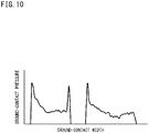
- FIG. 10 shows a ground-contact pressure distribution of the tire.
- the right side shows a ground-contact pressure distribution of a shoulder land portion Ls
- the left side shows a ground-contact pressure distribution of a middle land portion Lm.
- the outer edge in the circumferential direction of each land portion L has a shape that is convex inward.
- the ground-contact pressure is locally increased at the edge of each land portion L.
- a ground-contact pressure difference of about 200 kPa is confirmed in the middle land portion Lm
- a ground-contact pressure difference of about 250 kPa is confirmed in the shoulder land portion Ls.
- disturbance has occurred in the inner surface shape of the tread.
- the flow of the unvulcanized rubber in the mold influences the ground-contact surface shape and the ground-contact pressure distribution of the tire.
- the tire can be more sufficiently brought into contact with a road surface, so that it is expected that steering stability can be further improved.
- a local increase in ground-contact pressure is also suppressed, so that it is also expected that wear resistance can be improved.
- the present invention has been made in view of the above circumstances, and an object of the present invention is to provide a tire mold and a production method for a tire that are capable of making a ground-contact surface shape and a ground-contact pressure distribution appropriate, and a tire having a ground-contact surface shape and a ground-contact pressure distribution that are made appropriate.
- a tire mold according to an aspect of the present invention is a mold used for producing a tire including a tread having a tread surface that comes into contact with a road surface, at least two circumferential grooves being formed on the tread, thereby forming at least three land portions in the tread, the tread surface including the at least two circumferential grooves and at least three land surfaces that are outer surfaces of the at least three land portions.
- the tire mold includes a tread-forming surface for shaping the tread surface.
- the tread-forming surface includes projections for forming the circumferential grooves and land surface-forming portions for forming the land surfaces.
- a surface that has a contour represented by at least one circular arc and that is tangent to the three land surface-forming portions aligned in an axial direction with the projections interposed therebetween is a reference forming surface of the tread-forming surface.
- a land surface-forming portion located between the two projections is a curved land surface-forming portion.
- the projections each include a reference side surface that is a side surface on the land surface-forming portion side, and a back side surface that is a side surface located on a back side of the reference side surface.
- a tangent point between the curved land surface-forming portion and the reference forming surface is a reference tangent point.
- a boundary between the reference side surface and the curved land surface-forming portion is a reference boundary point.
- a point of intersection of the reference forming surface and a virtual line of the reference side surface that extends from the reference boundary point toward the reference forming surface is a reference virtual point of intersection.
- a contour of the curved land surface-forming portion is represented by one or more circular arcs.
- the reference boundary point is located inward of the reference forming surface.
- a distance from the reference virtual point of intersection to the reference tangent point on the one projection side is denoted by Xwlm
- a distance from the reference virtual point of intersection on the one projection side to the reference virtual point of intersection on the other projection side is denoted by Wcm
- a cross-sectional area of the one projection is denoted by Sam
- a cross-sectional area of the other projection is denoted by Sbm
- the distance Xwlm from the reference virtual point of intersection to the reference tangent point on the one projection side is set such that the following formula (1) is satisfied.
- a ratio of the distance from the reference virtual point of intersection to the reference boundary point to the cross-sectional area of the projection is not less than 0.0008 and not greater than 0.0040.
- a contour from the reference tangent point to the reference boundary point is represented by a circular arc that passes through the reference boundary point and that is tangent to the reference forming surface at the reference tangent point.
- a land surface-forming portion located on an outer side in the axial direction is a shoulder land surface-forming portion.
- a land surface-forming portion located adjacent to the curved land surface-forming portion is the shoulder land surface-forming portion.
- a side surface on the curved land surface-forming portion side of a projection located between the shoulder land surface-forming portion and the curved land surface-forming portion is the reference side surface, and a side surface on the shoulder land surface-forming portion side of said projection is the back side surface.
- a tangent point between the shoulder land surface-forming portion and the reference forming surface is a shoulder reference tangent point.
- a boundary between the back side surface and the shoulder land surface-forming portion is a shoulder reference boundary point.
- a point of intersection of the reference forming surface and a virtual line of the back side surface that extends from the shoulder reference boundary point to the reference forming surface is a shoulder reference virtual point of intersection.
- a distance from the shoulder reference virtual point of intersection to the shoulder reference boundary point at the back side surface is equal to a distance from the reference virtual point of intersection to the reference boundary point at the reference side surface.
- a distance from the shoulder reference virtual point of intersection to the shoulder reference tangent point is equal to the distance from the reference virtual point of intersection to the reference tangent point.
- a contour from the shoulder reference tangent point to the shoulder reference boundary point is represented by a circular arc that passes through the shoulder reference boundary point and that is tangent to the reference forming surface at the shoulder reference tangent point.
- any position that is on a virtual line of the reference side surface and that is between the reference boundary point and the reference virtual point of intersection is a vertical point.
- a circular arc that passes through the vertical point and that is tangent to the reference forming surface at the reference tangent point is a tangent point-side circular arc.
- Any position that is on the reference forming surface and that is between the reference tangent point and the reference virtual point of intersection is a horizontal point.
- a point of intersection of the tangent point-side circular arc and a normal line that passes through the horizontal point and that is normal to the reference forming surface is an intermediate boundary point.
- a circular arc that passes through the reference boundary point and that is tangent to the tangent point-side circular arc at the intermediate boundary point is a boundary-side circular arc.
- a contour from the reference tangent point to the intermediate boundary point is represented by the tangent point-side circular arc
- a contour from the intermediate boundary point to the reference boundary point is represented by the boundary-side circular arc.
- a ratio of a distance from the reference virtual point of intersection to the vertical point to the distance from the reference virtual point of intersection to the reference boundary point is not less than 0.40 and not greater than 0.60.
- a ratio of a distance from the reference virtual point of intersection to the horizontal point to the distance from the reference virtual point of intersection to the reference tangent point is not less than 0.40 and not greater than 0.60.
- a land surface-forming portion located on an outer side in the axial direction is a shoulder land surface-forming portion.
- a land surface-forming portion located adjacent to the curved land surface-forming portion is the shoulder land surface-forming portion.
- a side surface on the curved land surface-forming portion side of a projection located between the shoulder land surface-forming portion and the curved land surface-forming portion is the reference side surface, and a side surface on the shoulder land surface-forming portion side of said projection is the back side surface.
- a tangent point between the shoulder land surface-forming portion and the reference forming surface is a shoulder reference tangent point.
- a boundary between the back side surface and the shoulder land surface-forming portion is a shoulder reference boundary point.
- a point of intersection of the reference forming surface and a virtual line of the back side surface that extends from the shoulder reference boundary point to the reference forming surface is a shoulder reference virtual point of intersection.
- a distance from the shoulder reference virtual point of intersection to the shoulder reference boundary point at the back side surface is equal to a distance from the reference virtual point of intersection to the reference boundary point at the reference side surface.
- a distance from the shoulder reference virtual point of intersection to the shoulder reference tangent point is equal to the distance from the reference virtual point of intersection to the reference tangent point. Any position that is on the virtual line of the back side surface and that is between the shoulder reference boundary point and the shoulder reference virtual point of intersection is a shoulder vertical point.
- a circular arc that passes through the shoulder vertical point and that is tangent to the reference forming surface at the shoulder reference tangent point is a shoulder tangent point-side circular arc. Any position that is on the reference forming surface and that is between the shoulder reference tangent point and the shoulder reference virtual point of intersection is a shoulder horizontal point.
- a point of intersection of the shoulder tangent point-side circular arc and a normal line that passes through the shoulder horizontal point and that is normal to the reference forming surface is a shoulder intermediate boundary point.
- a circular arc that passes through the shoulder reference boundary point and that is tangent to the shoulder tangent point-side circular arc at the shoulder intermediate boundary point is a shoulder boundary-side circular arc.
- a contour from the shoulder reference tangent point to the shoulder intermediate boundary point is represented by the shoulder tangent point-side circular arc
- a contour from the shoulder intermediate boundary point to the shoulder reference boundary point is represented by the shoulder boundary-side circular arc.
- a distance from the shoulder reference virtual point of intersection to the shoulder vertical point is equal to the distance from the reference virtual point of intersection to the vertical point.
- a distance from the shoulder reference virtual point of intersection to the shoulder horizontal point is equal to the distance from the reference virtual point of intersection to the horizontal point.
- the tread includes a cap portion including the tread surface, and an unvulcanized rubber for the cap portion has a Mooney viscosity of not less than 80.
- a production method for a tire according to an aspect of the present invention includes the step of pressurizing and heating an unvulcanized tire by using any tire mold described above.
- a tire according to an aspect of the present invention is a tire including a tread having a tread surface that comes into contact with a road surface, at least two circumferential grooves being formed on the tread, thereby forming at least three land portions in the tread, the tread surface including the at least two circumferential grooves and at least three land surfaces that are outer surfaces of the at least three land portions.
- a surface that has a contour represented by at least one circular arc and that is tangent to the three land surfaces aligned in an axial direction with the circumferential grooves interposed therebetween is a reference surface of the tread surface.
- a land surface located between the two circumferential grooves is a curved land surface.
- the circumferential grooves each include a reference wall that is a wall on the curved land surface side, and a facing wall that is a wall facing the reference wall.
- a tangent point between the curved land surface and the reference surface is a reference tangent point.
- a boundary between the reference wall and the curved land surface is a reference boundary point.
- a point of intersection of the reference surface and a virtual line of the reference wall that extends from the reference boundary point toward the reference surface is a reference virtual point of intersection.
- a contour of the curved land surface is represented by one or more circular arcs.
- the reference boundary point is located inward of the reference surface.
- one circumferential groove has a smaller groove cross-sectional area
- the other circumferential groove has a larger groove cross-sectional area
- a distance from the reference virtual point of intersection to the reference boundary point on the one circumferential groove side is shorter, and a distance from the reference virtual point of intersection to the reference boundary point on the other circumferential groove side is longer.
- the ground-contact surface shape and the ground-contact pressure distribution of a tire can be made appropriate.
- a tire obtained by the tire mold and the production method for a tire an appropriate ground-contact surface shape and an appropriate ground-contact pressure distribution are obtained, and thus steering stability and wear resistance can be improved.
- a state where a tire is fitted on a normal rim, the internal pressure of the tire is adjusted to a normal internal pressure, and no load is applied to the tire is referred to as a normal state.
- the dimensions and angles of each component of the tire are measured in the normal state.
- the normal rim means a rim specified in a standard on which the tire is based.
- the "standard rim” in the JATMA standard, the "Design Rim” in the TRA standard, and the “Measuring Rim” in the ETRTO standard are normal rims.
- the normal internal pressure means an internal pressure specified in the standard on which the tire is based.
- the "highest air pressure” in the JATMA standard, the “maximum value” recited in “TIRE LOAD LIMITS AT VARIOUS COLD INFLATION PRESSURES" in the TRA standard, and the “INFLATION PRESSURE” in the ETRTO standard are normal internal pressures.
- the normal internal pressure of a tire for a passenger car is, for example, 180 kPa.
- a normal load means a load specified in the standard on which the tire is based.
- the "maximum load capacity" in the JATMA standard, the “maximum value” recited in the "TIRE LOAD LIMITS AT VARIOUS COLD INFLATION PRESSURES" in the TRA standard, and the “LOAD CAPACITY” in the ETRTO standard are normal loads.
- the normal load of a tire for a passenger car is, for example, a load corresponding to 88% of the above load.
- FIG. 1 shows a part of a pneumatic tire 2 (hereinafter, sometimes referred to simply as "tire 2") according to an embodiment of the present disclosure.
- the tire 2 is mounted to a passenger car.
- FIG. 1 shows a part of a cross-section of the tire 2 along a plane including the rotation axis of the tire 2.
- the right-left direction is the axial direction of the tire 2
- the up-down direction is the radial direction of the tire 2.
- the direction perpendicular to the surface of the sheet of FIG. 1 is the circumferential direction of the tire 2.
- an alternate long and short dash line CL represents the equator plane of the tire 2.
- the tire 2 includes a tread 4, a pair of sidewalls 6, a pair of clinches 8, a pair of beads 10, a carcass 12, a cord reinforcing layer 14, a pair of chafers 16, an inner liner 18, and a pair of rubber reinforcing layers 20.
- the outer surface of the tread 4 is a tread surface 22.
- the tread 4 comes into contact with a road surface at the tread surface 22.
- the tread 4 has the tread surface 22 which comes into contact with a road surface.
- the tread 4 is located outward of the cord reinforcing layer 14 in the radial direction.
- the tread 4 includes a base portion 24 and a cap portion 26.
- the base portion 24 forms a radially inner portion of the tread 4.
- the base portion 24 is formed from a crosslinked rubber for which heat generation properties are taken into consideration.
- the cap portion 26 is located radially outward of the base portion 24. In the tire 2, the cap portion 26 comes into contact with a road surface.
- the outer surface of the cap portion 26 is the above-described tread surface 22.
- the cap portion 26 is formed from a crosslinked rubber for which wear resistance and grip performance are taken into consideration.
- the tread 4 may be composed of only the cap portion 26.
- Each sidewall 6 extends from an end of the tread 4 inwardly in the radial direction along the carcass 12.
- the sidewall 6 is formed from a crosslinked rubber.
- Each clinch 8 is located radially inward of the sidewall 6. Although not shown, the clinch 8 comes into contact with a rim (not shown).
- the clinch 8 is formed from a crosslinked rubber for which wear resistance is taken into consideration.
- Each bead 10 is located axially inward of the clinch 8.
- the bead 10 includes a core 28 and an apex 30.
- the core 28 includes a wire made of steel.
- the apex 30 is located radially outward of the core 28.
- the apex 30 is formed from a crosslinked rubber that has high stiffness. As shown in FIG. 1 , the size of the apex 30 is smaller than that of a conventional apex.
- the core 28 may include two cores aligned in the axial direction.
- a later-described carcass ply is not turned up around the core 28, but an end portion of the carcass ply is interposed between these two cores.
- the carcass 12 is located inward of the tread 4, the pair of sidewalls 6, and the pair of clinches 8.
- the carcass 12 extends on and between one bead 10 and the other bead 10.
- the carcass 12 has a radial structure.
- the carcass 12 includes at least one carcass ply 32.
- the carcass 12 of the tire 2 is composed of one carcass ply 32.
- the carcass ply 32 is turned up around the core 28 of each bead 10.
- the carcass ply 32 includes a large number of cords aligned with each other, which are not shown.
- the cord reinforcing layer 14 includes a belt 34 and a band 36.
- the belt 34 forms an inner portion of the cord reinforcing layer 14, and the band 36 forms an outer portion of the cord reinforcing layer 14.
- the cord reinforcing layer 14 may be composed of only the belt 34, or may be composed of only the band 36.
- the belt 34 is laminated on the carcass 12 on the radially inner side of the tread 4.
- the belt 34 includes at least two belt plies 38 laminated in the radial direction.
- the belt 34 of the tire 2 is composed of two belt plies 38.
- Each of the two belt plies 38 includes a large number of cords aligned with each other, which are not shown. These cords are inclined relative to the equator plane CL.
- the material of each cord is steel.
- the band 36 is located inward of the tread 4 in the radial direction.
- the band 36 is located between the tread 4 and the belt 34 in the radial direction.
- the band 36 of the tire 2 includes a full band 36f and a pair of edge bands 36e located outward of the full band 36f.
- the band 36 may be composed of only the full band 36f, or may be composed of only the pair of edge bands 36e.
- the band 36 includes cords, which are not shown. In the full band 36f and the edge bands 36e, the cords are spirally wound in the circumferential direction. A cord formed from an organic fiber is used as each cord of the band 36.
- Each chafer 16 is located radially inward of the bead 10. Although not shown, the chafer 16 comes into contact with the rim.
- the chafer 16 includes a fabric and a rubber with which the fabric is impregnated.
- the chafer 16 may be composed of a member formed from a crosslinked rubber.
- the inner liner 18 is located inward of the carcass 12.
- the inner liner 18 forms an inner surface of the tire 2.
- the inner liner 18 is formed from a crosslinked rubber that has low gas permeability.
- Each rubber reinforcing layer 20 is located outward of the apex 30 in the axial direction.
- the rubber reinforcing layer 20 is located between the carcass 12 and the clinch 8.
- the rubber reinforcing layer 20 is formed from a crosslinked rubber.
- the material of the rubber reinforcing layer 20 is the same as that of the apex 30.
- the rubber reinforcing layer 20 does not have to be provided. In this case, an apex having a conventional size is adopted.
- grooves 40 are formed on the tread 4 of the tire 2 (specifically, the cap portion 26). Accordingly, a tread pattern is formed.
- Each groove 42 of the tire 2 shown in FIG. 1 is a part of the grooves 40 which form the tread pattern.
- the groove 42 extends in the circumferential direction.
- the groove 42 is a circumferential groove.
- the circumferential groove 42 has a groove width of not less than 9 mm and not greater than 20 mm, which is set as appropriate in accordance with the specifications of the tire 2.
- the circumferential groove 42 has a groove depth of not less than 5 mm and not greater than 15 mm.
- the groove width is represented as the distance from one edge of the groove 40 to the other edge of the groove 40.
- the groove depth is represented as the distance from the edge to the bottom. In the case where the edges are rounded, a groove width and a groove depth are specified on the basis of virtual edges obtained on the assumption that the edges are not rounded.
- FIG. 1 shows an example in which a plurality of circumferential grooves 42 formed on the tread 4 are arranged symmetrically with respect to the equator plane CL. These circumferential grooves 42 may be arranged asymmetrically with respect to the equator plane CL.
- At least two circumferential grooves 42 are formed on the tread 4 of the tire 2. Accordingly, at least three land portions 44 are formed in the tread 4.
- each circumferential groove 42 is a part of the tread surface 22.
- the tread surface 22 includes the at least two circumferential grooves 42 and at least three land surfaces 46 that are the outer surfaces of the at least three land portions 44. In the tread surface 22, the at least three land surfaces 46 are aligned in the axial direction with the circumferential grooves 42 interposed therebetween.
- Three circumferential grooves 42 are formed on the tread 4 shown in FIG. 1 .
- the circumferential groove 42 located on each outer side in the axial direction is a shoulder circumferential groove 42s.
- the circumferential groove 42 located adjacent to the shoulder circumferential groove 42s is a middle circumferential groove 42m.
- the middle circumferential groove 42m is located on the equator.
- the middle circumferential groove 42m is also referred to as crown circumferential groove.
- each shoulder circumferential groove 42s has a depth substantially equal to the groove depth of the middle circumferential groove 42m.
- the shoulder circumferential groove 42s may be shallower than the middle circumferential groove 42m, or the middle circumferential groove 42m may be shallower than the shoulder circumferential groove 42s.
- the ratio of the groove depth of one circumferential groove 42 to the groove depth of the other circumferential groove 42 is not less than 0.9 and not greater than 1.1, it is determined that the two circumferential grooves 42 have groove depths substantially equal to each other.
- the three circumferential grooves 42 are formed on the tread 4 so as to be aligned in the axial direction, thereby forming four land portions 44.
- the land portion 44 located on each outer side in the axial direction is a shoulder land portion 44s.
- the land portion 44 located inward of the shoulder land portion 44s in the axial direction is a middle land portion 44m.
- the middle land portion 44m is located at a center portion of the tread 4, and thus also referred to as crown land portion.
- the four land portions 44 formed in the tread 4 include a pair of middle land portions 44m and a pair of shoulder land portions 44s.
- FIG. 2 shows a part of the tread 4 shown in FIG. 1 .
- the right-left direction is the axial direction of the tire 2
- the up-down direction is the radial direction of the tire 2.
- the direction perpendicular to the surface of the sheet of FIG. 2 is the circumferential direction of the tire 2.
- the contour of the tread surface 22 is schematically represented.
- the land portions 44 of the tire 2 include land portions 44 each having a land surface 46 having a rounded shape.
- the rounded shapes of the land surfaces 46 are exaggeratedly represented.
- the shoulder circumferential groove 42s is present between a land surface 46s (hereinafter, shoulder land surface) of the shoulder land portion 44s and a land surface 46m (hereinafter, middle land surface) of the middle land portion 44m.
- the circumferential groove 42 between the right and left middle land surfaces 46m is the middle circumferential groove 42m.
- the land surface 46 located on the left side in the sheet of FIG. 2 is the middle land surface 46m.
- a middle circumferential groove 42m is located adjacent to the middle land surface 46m.
- Another middle land surface 46m is located adjacent to the middle circumferential groove 42m.
- a shoulder circumferential groove 42s is located adjacent to the middle land surface 46m.
- a shoulder land surface 46s is located adjacent to the shoulder circumferential groove 42s. That is, three land surfaces 46 are aligned in the axial direction with the circumferential grooves 42 interposed therebetween.
- the land surface 46 located between the two circumferential grooves 42 that is, one middle land surface 46m, has a shape that is convex outward.
- This middle land surface 46m is also referred to as curved land surface 46B.
- the land surface 46 located adjacent to the curved land surface 46B across the middle circumferential groove 42m, that is, the other middle land surface 46m, is also referred to as first land surface 46f.
- the middle circumferential groove 42m is also referred to as first circumferential groove 42f.
- the land surface 46 located adjacent to the curved land surface 46B across the shoulder circumferential groove 42s, that is, the shoulder land surface 46s, is also referred to as second land surface 46n.
- the shoulder circumferential groove 42s is also referred to as second circumferential groove 42n.
- a groove cross-sectional area of the first circumferential groove 42f is smaller than a groove cross-sectional area of the second circumferential groove 42n.
- the first circumferential groove 42f has a smaller groove cross-sectional area
- the second circumferential groove 42n has a larger groove cross-sectional area.
- the groove cross-sectional area of the first circumferential groove 42f may be larger than the groove cross-sectional area of the second circumferential groove 42n, or the groove cross-sectional area of the first circumferential groove 42f may be equal to the groove cross-sectional area of the second circumferential groove 42n.
- an alternate long and two short dashes line TBL represents a reference surface of the tread surface 22.
- the reference surface TBL of the tread surface 22 represents a virtual tread surface obtained on the assumption that the grooves 40 are not present on the tread 4.
- a surface that has a contour represented by at least one circular arc and that is tangent to the three land surfaces 46 aligned in the axial direction with the circumferential grooves 42 interposed therebetween is the reference surface TBL of the tread surface 22.
- the reference surface TBL of the tread surface 22 is tangent to the first land surface 46f, the curved land surface 46B, and the second land surface 46n.
- the contour of the reference surface TBL is represented by a plurality of circular arcs aligned in the axial direction which are not shown
- the contour of the reference surface TBL is formed such that: one circular arc and another circular arc located adjacent to the one circular arc are tangent to each other at the boundary between both circular arcs; and a circular arc located on the inner side in the axial direction has a radius larger than that of the circular arc located on the outer side.
- one circular arc and another circular arc may be connected by a straight line that is tangent to both circular arcs.
- a state where the tire 2 is fitted on the normal rim, the internal pressure of the tire 2 is adjusted to 5% of the normal internal pressure, and no load is applied to the tire 2 is referred to as a reference state.
- the contour of the tread surface 22 of the tire 2 is represented by the contour of the tread surface 22 in the reference state, or the contour of a tread-forming surface of a later-described mold.
- the contour of the reference surface TBL of the tread surface 22 may be specified, for example, on the basis of a contour of the tread surface 22 that is obtained by analyzing cross-section image data of the tire 2 in the reference state taken by a computer tomography method using X-rays (hereinafter, X-ray CT method) or shape data of the tread surface 22 of the tire 2 in the reference state measured using a profile measuring device (not shown) having a laser displacement meter.
- X-ray CT method X-ray CT method
- the contour of the reference surface TBL of the tread surface 22 is represented by a single circular arc that is tangent to the three land surfaces 46 aligned in the axial direction.
- Each circumferential groove 42 includes a bottom 48 and a pair of walls 50.
- reference character Bt represents the boundary between the wall 50 and the land surface 46.
- the boundary Bt is also referred to as boundary point.
- An alternate long and two short dashes line Lt is a straight line that extends from the boundary point Bt toward the reference surface TBL and that is tangent to the contour line of the wall 50 at the boundary point Bt.
- the straight line Lt is a virtual line of the wall 50.
- Reference character Vt represents the point of intersection of the virtual line Lt and the reference surface TBL. The point of intersection Vt is also referred to as virtual point of intersection.
- a groove cross-sectional area of each circumferential groove 42 is represented by the area of a region surrounded by one wall 50, the bottom 48, the other wall 50, the virtual line Lt of the other wall 50, the reference surface TBL, and the virtual line Lt of the one wall 50.
- the curved land surface 46B is located between the two circumferential grooves 42.
- the wall 50 located on the curved land surface 46B side is also referred to as reference wall 50a.
- the wall 50 facing the reference wall 50a is also referred to as facing wall 50b.
- Each circumferential groove 42 located adjacent to the curved land surface 46B includes a reference wall 50a which is the wall 50 on the curved land surface 46B side, and a facing wall 50b which is the wall 50 facing the reference wall 50a.
- reference character BB1t represents the boundary between the reference wall 50a (hereinafter, first reference wall) of the first circumferential groove 42f and the curved land surface 46B.
- the boundary BB1t is a reference boundary point (hereinafter, first reference boundary point).
- An alternate long and two short dashes line BL1t is a virtual line of the first reference wall 50a.
- Reference character BV1t represents a virtual point of intersection represented as the point of intersection of the virtual line BL1t of the first reference wall 50a and the reference surface TBL.
- the virtual point of intersection BV1t is a reference virtual point of intersection (hereinafter, first reference virtual point of intersection).
- a double-headed arrow Xd1t represents the distance from the first reference virtual point of intersection BV1t to the first reference boundary point BB1t. The distance Xd1t is measured along the virtual line BL1t of the first reference wall 50a.
- reference character BB2t represents the boundary between the reference wall 50a (hereinafter, second reference wall) of the second circumferential groove 42n and the curved land surface 46B.
- the boundary BB2t is a reference boundary point (hereinafter, second reference boundary point).
- An alternate long and two short dashes line BL2t is a virtual line of the second reference wall 50a.
- Reference character BV2t indicates a virtual point of intersection represented as the point of intersection of the virtual line BL2t of the second reference wall 50a and the reference surface TBL.
- the virtual point of intersection BV2t is a reference virtual point of intersection (hereinafter, second reference virtual point of intersection).
- a double-headed arrow Xd2t represents the distance from the second reference virtual point of intersection BV2t to the second reference boundary point BB2t. The distance Xd2t is measured along the virtual line BL2t of the second reference wall 50a.
- the tire 2 described above is produced as follows. Although not described in detail, a rubber composition in an unvulcanized state (hereinafter, also referred to as an unvulcanized rubber) for components included in the tire 2 such as the tread 4, the sidewalls 6, and the beads 10 is prepared in the production of the tire 2.
- the unvulcanized rubber is obtained by mixing a base rubber and chemicals using a kneading machine (not shown) such as a Banbury mixer.
- Examples of the base rubber include natural rubber (NR), butadiene rubber (BR), styrene-butadiene rubber (SBR), isoprene rubber (IR), ethylene-propylene rubber (EPDM), chloroprene rubber (CR), acrylonitrile-butadiene rubber (NBR), and isobutylene-isoprene-rubber (IIR).
- Examples of the chemicals include reinforcing agents such as carbon black and silica, plasticizers such as aromatic oil, fillers such as zinc oxide, lubricants such as stearic acid, antioxidants, processing aids, sulfur, and vulcanization accelerators.
- the shape of the unvulcanized rubber is adjusted to prepare preforms for tire components.
- a tire building machine (not shown), the preforms for the tread 4, the sidewalls 6, the bead 10, etc., are combined to prepare the tire 2 in an unvulcanized state (hereinafter, also referred to as unvulcanized tire).
- the unvulcanized tire is put into a mold of a vulcanizing machine (not shown).
- the unvulcanized tire is pressurized and heated within the mold to obtain the tire 2.
- the tire 2 is a vulcanized-molded product of the unvulcanized tire.
- the production method for the tire 2 includes a step of preparing an unvulcanized tire, and a step of pressurizing and heating the unvulcanized tire using a mold.
- the vulcanization conditions such as temperature, pressure, and time are not particularly limited, and general vulcanization conditions are adopted.
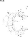
- FIG. 3 shows a part of a cross-section of a tire mold 56 along a plane including the rotation axis of the tire 2.
- the mold 56 is used for producing the tire 2 shown in FIG. 1 .
- the right-left direction is the radial direction of the tire 2
- the up-down direction is the axial direction of the tire 2.
- the direction perpendicular to the surface of the sheet of FIG. 3 is the circumferential direction of the tire 2.
- An alternate long and short dash line CL represents the equator plane of the tire 2.
- the dimensions of the mold 56 are represented below on the basis of the dimensions of the tire 2.
- the mold 56 includes a tread ring 58, a pair of side plates 60, and a pair of bead rings 62.
- the mold 56 is a segmented mold. In FIG. 3 , the mold 56 is in a state where the tread ring 58, the pair of side plates 60, and the pair of bead rings 62 are combined, that is, in a closed state.
- the tread ring 58 forms a radially outer portion of the mold 56.
- the tread ring 58 has a tread-forming surface 64 in the inner surface thereof.
- the tread-forming surface 64 shapes the tread surface 22 of the tire 2 in the outer surface of an unvulcanized tire 2r.
- the tread ring 58 of the mold 56 includes a large number of segments 66. These segments 66 are arranged in a ring shape.
- Each side plate 60 is located radially inward of the tread ring 58.
- the side plate 60 is connected to an end of the tread ring 58.
- the side plate 60 has a sidewall-forming surface 68 in the inner surface thereof.
- the sidewall-forming surface 68 shapes a side surface of the tire 2 in the outer surface of the unvulcanized tire 2r.
- Each bead ring 62 is located radially inward of the side plate 60.
- the bead ring 62 is connected to an end of the side plate 60.
- the bead ring 62 has a bead-forming surface 70 in the inner surface thereof.
- the bead-forming surface 70 shapes a bead 10 portion of the tire 2, specifically, a portion to be fitted to the rim, in the outer surface of the unvulcanized tire 2r.
- a cavity face 72 for shaping the outer surface of the tire 2 is formed by combining the large number of segments 66, the pair of side plates 60, and the pair of bead rings 62.
- the cavity face 72 includes the tread-forming surface 64, a pair of the sidewall-forming surfaces 68, and a pair of the bead-forming surfaces 70.
- the unvulcanized tire 2r is pressed against the cavity face 72 of the mold 56 by a rigid core or an expanded bladder. Accordingly, the outer surface of the tire 2 is shaped.
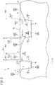
- FIG. 4 shows a cross-section of the tread ring 58 which forms a part of the mold 56 shown in FIG. 3 .
- the contour of the tread-forming surface 64 for shaping the tread surface 22 is schematically represented.
- the right-left direction is the axial radial direction of the tire 2
- the up-down direction is the radial direction of the tire 2.
- the direction perpendicular to the surface of the sheet of FIG. 4 is the circumferential direction of the tire 2.
- the tread surface 22 of the tire 2 includes the at least two circumferential grooves 42 and the at least three land surfaces 46 which are the outer surfaces of the at least three land portions 44. Therefore, in the mold 56, the tread-forming surface 64 for shaping the tread surface 22 includes at least two projections 74 for forming the at least two circumferential grooves 42, and at least three land surface-forming portions 76 for forming the at least three land surfaces 46.
- the projection 74 for shaping the first circumferential groove 42f is a first projection 74f.
- the projection 74 for shaping the second circumferential groove 42n is a second projection 74n.
- the groove cross-sectional area of the first circumferential groove 42f is smaller than the groove cross-sectional area of the second circumferential groove 42n.
- a cross-sectional area of the first projection 74f is smaller than a cross-sectional area of the second projection 74n.
- the first projection 74f has a smaller cross-sectional area, and the second projection 74n has a larger cross-sectional area.
- the land surface-forming portion 76 for shaping the curved land surface 46B is a curved land surface-forming portion 76B.
- the land surface-forming portion 76 for shaping the first land surface 46f is a first land surface-forming portion 76f.
- the land surface-forming portion 76 for shaping the second land surface 46n is a second land surface-forming portion 76n.
- the first projection 74f is located adjacent to the first land surface-forming portion 76f.
- the curved land surface-forming portion 76B is located adjacent to the first projection 74f.
- the second projection 74n is located adjacent to the curved land surface-forming portion 76B.
- the second land surface-forming portion 76n is located adjacent to the second projection 74n. That is, the three land surface-forming portions 76 are aligned in the axial direction with the projections 74 interposed therebetween.
- the land surface-forming portion 76 located between the two projections 74 is the curved land surface-forming portion 76B.
- the two land surface-forming portions 76 located adjacent to the curved land surface-forming portion 76B are the first land surface-forming portion 76f and the second land surface-forming portion 76n.
- the land surface-forming portion 76 located on the outer side in the axial direction is a shoulder land surface-forming portion 76s for shaping the shoulder land surface 46s.
- the curved land surface-forming portion 76B is a middle land surface-forming portion 76m for shaping one middle land surface 46m.
- the first land surface-forming portion 76f located adjacent to the curved land surface-forming portion 76B is a middle land surface-forming portion 76m for shaping the other middle land surface 46m.
- the first projection 74f located between the first land surface-forming portion 76f and the curved land surface-forming portion 76B is a middle projection 74m for shaping the middle circumferential groove 42m.
- the second land surface-forming portion 76n located adjacent to the curved land surface-forming portion 76B is the shoulder land surface-forming portion 76s.
- the second projection 74n located between the second land surface-forming portion 76n and the curved land surface-forming portion 76B is a shoulder projection 74s for shaping the shoulder circumferential groove 42s.
- an alternate long and two short dashes line FBL represents a reference forming surface of the tread-forming surface 64.
- the reference forming surface FBL of the tread-forming surface 64 corresponds to the above-described reference surface TBL of the tread surface 22.
- a surface that has a contour represented by at least one circular arc and that is tangent to the three land surface-forming portions 76 which are aligned in the axial direction with the projections 74 interposed therebetween is the reference forming surface FBL of the tread-forming surface 64.
- the reference forming surface FBL of the tread-forming surface 64 is tangent to the first land surface-forming portion 76f, the curved land surface-forming portion 76B, and the second land surface-forming portion 76n from the left side of the sheet of FIG. 4 .
- the contour of the reference forming surface FBL is represented by a plurality of circular arcs aligned in the axial direction which are not shown
- the contour of the reference forming surface FBL is formed such that: one circular arc and another circular arc located adjacent to the one circular arc are tangent to each other at the boundary between both circular arcs; and a circular arc located on the inner side in the axial direction has a radius larger than that of the circular arc located on the outer side.
- Each projection 74 includes a top surface 78 and a pair of side surfaces 80.
- reference character Bm represents the boundary between the side surface 80 and the land surface-forming portion 76.
- the boundary Bm is also referred to as boundary point.
- An alternate long and two short dashes line Lm is a straight line that extends from the boundary point Bm toward the reference forming surface FBL and that is tangent to the contour line of the side surface 80 at the boundary point Bm.
- the straight line Lm is a virtual line of the side surface 80.
- Reference character Vm represents the point of intersection of the virtual line Lm and the reference forming surface FBL. The point of intersection Vm is also referred to as virtual point of intersection.
- a cross-sectional area of the projection 74 is represented as the area of a region surrounded by one side surface 80, the top surface 78, the other side surface 80, the virtual line Lm of the other side surface 80, the reference forming surface FBL, and the virtual line Lm of the one side surface 80.
- the curved land surface-forming portion 76B is located between the two projections 74.
- the side surface 80 located on the curved land surface-forming portion 76B side is also referred to as reference side surface 80a.
- the side surface 80 located on the back side of the reference side surface 80a is also referred as back side surface 80b.
- Each projection 74 located adjacent to the curved land surface-forming portion 76B includes a reference side surface 80a which is the side surface 80 on the curved land surface-forming portion 76B side, and a back side surface 80b which is the side surface 80 located on the back side of the reference side surface 80a.
- reference character BB1m represents the boundary between the reference side surface 80a (hereinafter, first reference side surface) of the first projection 74f and the curved land surface-forming portion 76B.
- the boundary BB1m is a reference boundary point (hereinafter, first reference boundary point).
- An alternate long and two short dashes line BL1m is a virtual line of the first reference side surface 80a.
- Reference character BV1m represents a virtual point of intersection represented as the point of intersection of the virtual line BL1m of the first reference side surface 80a and the reference forming surface FBL.
- the virtual point of intersection BV1m is a reference virtual point of intersection (hereinafter, first reference virtual point of intersection).
- a double-headed arrow Xd1m represents the distance from the first reference virtual point of intersection BV1m to the first reference boundary point BB1m. The distance Xd1m is measured along the virtual line BL1m of the first reference side surface 80a.
- reference character BB2m represents the boundary between the reference side surface 80a (hereinafter, second reference side surface) of the second projection 74n and the curved land surface-forming portion 76B.
- the boundary BB2m is a reference boundary point (hereinafter, second reference boundary point).
- An alternate long and two short dashes line BL2m is a virtual line of the second reference side surface 80a.
- Reference character BV2m represents a virtual point of intersection represented as the point of intersection of the virtual line BL2m of the second reference side surface 80a and the reference forming surface FBL.
- the virtual point of intersection BV2m is a reference virtual point of intersection (hereinafter, second reference virtual point of intersection).
- a double-headed arrow Xd2m represents the distance from the second reference virtual point of intersection BV2m to the second reference boundary point BB2m. The distance Xd2m is measured along the virtual line BL2m of the second reference side surface 80a.
- the flow of the unvulcanized rubber that is generated by pressing the projections 74 against the unvulcanized tire 2r is controlled on the basis of the shapes of the land surface-forming portions 76.
- the circumferential grooves 42 are formed on the cap portion 26 of the tread 4.
- the projections 74 on the tread-forming surface 64 press the cap portion 26.
- the flow of the unvulcanized rubber, for the cap portion 26, generated by pressing the projections 74 against the unvulcanized tire 2r is controlled on the basis of the shapes of the land surface-forming portions 76.
- the shapes of the land surface-forming portions 76 will be described.
- the reference forming surface FBL of the tread-forming surface 64 is tangent to the first land surface-forming portion 76f, the curved land surface-forming portion 76B, and the second land surface-forming portion 76n which are included in the tread-forming surface 64.
- reference character Tm represents the tangent point between the curved land surface-forming portion 76B and the reference forming surface FBL.
- the tangent point Tm is a reference tangent point.
- the contour of the curved land surface-forming portion 76B is represented by one or more circular arcs.
- the above-described first reference boundary point BB1m is also the end on the first projection 74f side of the curved land surface-forming portion 76B.
- the above-described second reference boundary point BB2m is also the end on the second projection 74n side of the curved land surface-forming portion 76B.
- the end BB1m on the first projection 74f side of the curved land surface-forming portion 76B is located inward of the reference forming surface FBL of the tread-forming surface 64 in the radial direction.
- the end BB2m on the second projection 74n side of the curved land surface-forming portion 76B is also located inward of the reference forming surface FBL in the radial direction.
- the unvulcanized rubber for the cap portion 26 flows toward the portion between the two projections 74, that is, the curved land surface-forming portion 76B.
- the contour of the curved land surface-forming portion 76B is formed such that the ends BB1m and BB2m of the curved land surface-forming portion 76B are located inward of the reference forming surface FBL.
- the volume of the unvulcanized rubber that flows to the curved land surface-forming portion 76B is limited, and thus disturbance is inhibited from occurring in the flow of the unvulcanized rubber pressed by the projections 74.
- the first projection 74f has a smaller cross-sectional area
- the second projection 74n has a larger groove cross-sectional area.
- the volume of the unvulcanized rubber pressed by the second projection 74n is larger than the volume of the unvulcanized rubber pressed by the first projection 74f.
- the distance Xd2m from the second reference virtual point of intersection BV2m to the second reference boundary point BB2m on the second projection 74n side is longer than the distance Xd1m from the first reference virtual point of intersection BV1m to the first reference boundary point BB1m on the first projection 74f side.
- the distance Xd1m from the first reference virtual point of intersection BV1m to the first reference boundary point BB1m on the first projection 74f side is shorter, and the distance Xd2m from the second reference virtual point of intersection BV2m to the second reference boundary point BB2m on the second projection 74n side is longer.
- the volume of the unvulcanized rubber that flows to the curved land surface-forming portion 76B is effectively limited on the second projection 74n side having a larger cross-sectional area.
- the flow of the unvulcanized rubber on the first projection 74f side and the flow of the unvulcanized rubber on the second projection 74n side are controlled in a well-balanced manner, and thus disturbance is less likely to occur in the flow of the unvulcanized rubber.
- the curved land surface 46B in which the shape of the curved land surface-forming portion 76B is reflected is formed. Since disturbance of the inner surface shape of the tread 4 is also inhibited, the inner surface of the tread 4 is formed in an appropriate shape.
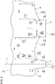
- the right-left direction corresponds to the axial direction of the tire 2.
- the up-down direction corresponds to the circumferential direction of the tire 2.
- the ground-contact surface shape is obtained by tracing the contour of each land portion 44 on a ground-contact surface obtained by applying a load equal to the normal load to the tire 2 in the normal state and pressing the tire 2 against a road surface, using a tire ground-contact shape measuring device (not shown).
- a tire ground-contact shape measuring device (not shown).
- the tire 2 is placed such that the axial direction thereof is parallel to the road surface, and the above load is applied to the tire 2 in a direction perpendicular to the road surface.
- the road surface is formed as a flat surface.
- the tire 2 is pressed against the flat road surface.
- the ground-contact surface shape, shown in FIG. 9 of the tire produced by the conventional mold is also obtained in the same manner.
- the outer edge in the circumferential direction of the middle land portion 44m located between each shoulder circumferential groove 42s and the middle circumferential groove 42m does not have a shape that is convex inward as in the outer edge in the circumferential direction of each middle land portion confirmed for the tire produced by the conventional mold and shown in FIG. 9 , but has a shape that bulges outward.
- the area of the ground-contact surface is clearly increased, so that the tire 2 can more sufficiently come into contact with a road surface than the tire produced by the conventional mold. With the mold 56, the steering stability of the tire 2 can be further improved.
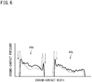
- the vertical axis represents ground-contact pressure
- the horizontal axis represents a position in the ground-contact width direction of the ground-contact surface.
- the left side shows a ground-contact pressure distribution of the middle land portion 44m
- the right side shows a ground-contact pressure distribution of the shoulder land portion 44s.
- the ground-contact pressure distribution is obtained by applying a load equal to the normal load to the tire 2 in the normal state and pressing the tire 2 against a road surface, using a tire ground-contact pressure measuring device (not shown).
- a tire ground-contact pressure measuring device (not shown).
- the tire 2 is placed such that the axial direction thereof is parallel to the road surface, and the above load is applied to the tire 2 in a direction perpendicular to the road surface.
- the road surface is formed as a flat surface.
- a ground-contact pressure distribution, shown in FIG. 10 of the tire produced by the conventional mold is also obtained in the same manner.
- the ground-contact pressure distribution indicated by a dotted line is the ground-contact pressure distribution of the tire produced by the conventional mold.
- the increase in ground-contact pressure at each edge of the middle land portion 44m is suppressed as compared to the increase in ground-contact pressure at each edge of the middle land portion confirmed for the tire produced by the conventional mold and shown in FIG. 10 .
- the ground-contact pressure difference in the middle land portion 44m is reduced to about 55 kPa. The local increase in ground-contact pressure is clearly suppressed, so that the wear resistance of the tire 2 can be further improved with the mold 56.
- the ground-contact surface shape and the ground-contact pressure distribution of the tire 2 can be made appropriate, so that improvement of the steering stability and the wear resistance of the tire 2 can be achieved.
- a double-headed arrow Wcm represents the distance from the first reference virtual point of intersection BV1m to the second reference virtual point of intersection BV2m.
- the distance Wcm is represented as the length of a line segment connecting the first reference virtual point of intersection BV1m and the second reference virtual point of intersection BV2m.
- a double-headed arrow Xwlm represents the distance from the first reference virtual point of intersection BV1m to the reference tangent point Tm.
- the distance Xwlm is represented as the length of a line segment connecting the first reference virtual point of intersection BV1m and the reference tangent point Tm.
- a double-headed arrow Xw2m represents the distance from the second reference virtual point of intersection BV2m to the reference tangent point Tm.
- the distance Xw2m is represented as the length of a line segment connecting the second reference virtual point of intersection BV2m and the reference tangent point Tm.
- the position of the reference tangent point Tm which is the tangent point between the curved land surface-forming portion 76B and the reference forming surface FBL, is preferably determined on the basis of the cross-sectional areas of the projections 74 located on both sides of the curved land surface-forming portion 76B.
- the distance Xwlm is preferably set such that the following formula (1) represented by using the distance Xwlm, the distance Wcm, the cross-sectional area Sam, and the cross-sectional area Sbm is satisfied.
- the reference tangent point Tm is set on the first reference boundary point BB1m side. In the mold 56, the flow of the unvulcanized rubber to the first projection 74f side having a smaller cross-sectional area is promoted. In the mold 56, in the case where the cross-sectional area Sam of the first projection 74f is larger than the cross-sectional area Sbm of the second projection 74n, the reference tangent point Tm is set on the second reference boundary point BB2m side. In this case, the flow of the unvulcanized rubber to the second projection 74n side is promoted.
- the flow of the unvulcanized rubber on the first projection 74f side and the flow of the unvulcanized rubber on the second projection 74n side are controlled in a well-balanced manner. Since disturbance is less likely to occur in the flow of the unvulcanized rubber, the curved land surface 46B in which the shape of the curved land surface-forming portion 76B is reflected is formed. With the mold 56 and the production method for the tire 2 using the mold 56, the ground-contact surface shape and the ground-contact pressure distribution of the tire 2 can be made appropriate, so that improvement of the steering stability and the wear resistance of the tire 2 can be achieved.
- the ratio (Xdm/Sm) of a distance Xdm from a reference virtual point of intersection BVm to a reference boundary point BBm to the cross-sectional area Sm of the projection 74 is preferably not less than 0.0008 and preferably not greater than 0.0040.
- the ratio (Xdm/Sm) is set so as to be not less than 0.0008, the shape of the curved land surface-forming portion 76B effectively contributes to limiting the flow of the unvulcanized rubber pressed by the projection 74. Even when there is a difference between the cross-sectional areas of the projections 74 located on both sides of the curved land surface-forming portion 76B, disturbance is less likely to occur in the flow of the unvulcanized rubber.
- the curved land surface 46B in which the shape of the curved land surface-forming portion 76B is reflected is formed. From this viewpoint, the ratio (Xdm/Sm) is more preferably not less than 0.0014 and further preferably not less than 0.0020.
- the ratio (Xdm/Sm) is set so as to be not greater than 0.0040, the flow of the unvulcanized rubber pressed by the projection 74 is appropriately maintained. In this case as well, even when there is a difference between the cross-sectional areas of the projections 74 located on both sides of the curved land surface-forming portion 76B, disturbance is less likely to occur in the flow of the unvulcanized rubber.
- the curved land surface 46B in which the shape of the curved land surface-forming portion 76B is reflected is formed. From this viewpoint, the ratio (Xdm/Sm) is more preferably not greater than 0.0034 and further preferably not greater than 0.0028.
- the cross-sectional area Sam of the first projection 74f is smaller than the cross-sectional area Sbm of the second projection 74n.
- the ratio (Xdlm/Sam) of the distance Xd1m from the first reference virtual point of intersection BV1m to the first reference boundary point BB1m to the cross-sectional area Sam of the first projection 74f on the first projection 74f side is preferably not less than 0.0008 and not greater than 0.0040, and the ratio (Xd2m/Sbm) of the distance Xd
- the contour of the curved land surface-forming portion 76B is represented by one or more circular arcs.
- the contour of the curved land surface-forming portion 76B is preferably represented by a circular arc that passes through the reference boundary point BBm and that is tangent to the reference forming surface FBL at the reference tangent point Tm.
- the contour of the curved land surface-forming portion 76B is preferably represented by a circular arc that passes through the first reference boundary point BB 1m and that is tangent to the reference forming surface FBL at the reference tangent point Tm, and a circular arc that passes through the second reference boundary point BB2m and that is tangent to the reference forming surface FBL at the reference tangent point Tm.
- the flow of the unvulcanized rubber on the first projection 74f side and the flow of the unvulcanized rubber on the second projection 74n side are controlled in a well-balanced manner. Disturbance is less likely to occur in the flow of the unvulcanized rubber, and thus, with the mold 56, the curved land surface 46B in which the shape of the curved land surface-forming portion 76B is reflected is formed.
- the ground-contact surface shape and the ground-contact pressure distribution of the tire 2 can be made appropriate, so that improvement of the steering stability and the wear resistance of the tire 2 can be achieved.
- the contour of the curved land surface-forming portion 76B is represented by one circular arc.
- the shoulder projection 74 located adjacent to the curved land surface-forming portion 76B is the shoulder projection 74s
- the shoulder land surface 46s of the tire 2 is formed by the second land surface-forming portion 76n in FIG. 4 .
- the following will describe the contour of the second land surface-forming portion 76n for forming the shoulder land surface 46s, that is, the shoulder land surface-forming portion 76s, with reference to FIG. 4 .
- the second projection 74n is located between the shoulder land surface-forming portion 76s and the curved land surface-forming portion 76B.
- the side surface 80 on the curved land surface-forming portion 76B side is the reference side surface 80a
- the side surface 80 on the shoulder land surface-forming portion 76s side is the back side surface 80b.
- reference character Tsm represents the tangent point between the shoulder land surface-forming portion 76s and the reference forming surface FBL.
- the tangent point Tsm is a shoulder reference tangent point.
- the shoulder reference tangent point Tsm is specified by the inner end of the tangent line between the shoulder land surface-forming portion 76s and the reference forming surface FBL.
- reference character BBsm represents the boundary between the back side surface 80b of the second projection 74n and the shoulder land surface-forming portion 76s.
- the boundary BBsm is a shoulder reference boundary point.
- An alternate long and two short dashes line BLsm is a virtual line of the back side surface 80b.
- Reference character BVsm represents a virtual point of intersection represented as the point of intersection of the virtual line BLsm of the back side surface 80b and the reference forming surface FBL.
- the virtual point of intersection BVsm is a shoulder reference virtual point of intersection.
- a double-headed arrow Xdsm represents the distance from the shoulder reference virtual point of intersection BVsm to the shoulder reference boundary point BBsm.
- the distance Xdsm is measured along the virtual line BLsm of the back side surface 80b.
- a double-headed arrow Xwsm represents the distance from the shoulder reference virtual point of intersection BVsm to the shoulder reference tangent point Tsm.
- the distance Xwsm is represented as the length of a line segment connecting the shoulder reference virtual point of intersection BVsm and the shoulder reference tangent point Tsm.
- the contour from the shoulder reference boundary point BBsm to the shoulder reference tangent point Tsm is formed similar to the contour, of the curved land surface-forming portion 76B, from the second reference boundary point BB2m to the reference tangent point Tm.
- the distance Xdsm from the shoulder reference virtual point of intersection BVsm to the shoulder reference boundary point BBsm is equal to the distance Xd2m from the second reference virtual point of intersection BV2m to the second reference boundary point BB2m.
- the distance Xwsm from the shoulder reference virtual point of intersection BVsm to the shoulder reference tangent point Tsm is equal to the distance Xw2m from the second reference virtual point of intersection BV2m to the reference tangent point Tm.
- the contour, of the shoulder land surface-forming portion 76s, from the shoulder reference boundary point BBsm to the shoulder reference tangent point Tsm is represented by a circular arc that passes through the shoulder reference boundary point BBsm and that is tangent to the reference forming surface FBL at the shoulder reference tangent point Tsm.
- the shoulder reference boundary point BBsm is also the end on the second projection 74n side of the shoulder land surface-forming portion 76s. As shown in FIG. 4 , the end BBsm on the second projection 74n side of the shoulder land surface-forming portion 76s is located inward of the reference forming surface FBL of the tread-forming surface 64 in the radial direction.
- the unvulcanized rubber for the cap portion 26 flows toward the portion that is axially outward of the second projection 74n, that is, the portion where the shoulder land portion 44s is to be formed.
- the contour of the shoulder land surface-forming portion 76s is formed such that the end BBsm of the shoulder land surface-forming portion 76s is located inward of the reference forming surface FBL of the tread-forming surface 64.
- the volume of the unvulcanized rubber that flows to the portion where the shoulder land portion 44s is to be formed is limited, and thus disturbance is less likely to occur in the flow of the unvulcanized rubber pressed by the second projection 74n.
- the shoulder land surface 46s in which the shape of the shoulder land surface-forming portion 76s is reflected is formed. Since disturbance of the inner surface shape of the tread 4 is also inhibited, the inner surface of the tread 4 is formed in an appropriate shape.
- the outer edge in the circumferential direction of each shoulder land portion 44s does not have a shape that is convex inward as in the outer edge in the circumferential direction of each shoulder land portion confirmed for the tire produced by the conventional mold and shown in FIG. 9 , but has a shape that bulges outward.
- the area of the ground-contact surface is clearly increased, so that the tire 2 can more sufficiently come into contact with a road surface than the tire produced by the conventional mold. With the mold 56, the steering stability of the tire 2 can be further improved.
- the increase in ground-contact pressure at each edge of the shoulder land portion 44s is suppressed as compared to the increase in ground-contact pressure at each edge of the shoulder land portion confirmed for the tire produced by the conventional mold and shown in FIG. 10 .
- the ground-contact pressure difference in the shoulder land portion 44s is reduced to about 70 kPa. The local increase in ground-contact pressure is clearly suppressed, so that the wear resistance of the tire 2 can be further improved with the mold 56.
- the tire 2 shown in FIG. 1 is produced using the above-described mold 56 having the tread-forming surface 64. Next, the contour of the tread surface 22 shaped by the tread-forming surface 64 will be described.
- the middle land surface 46m is the curved land surface 46B located between the first circumferential groove 42f as the middle circumferential groove 42m and the second circumferential groove 42n as the shoulder circumferential groove 42s.
- the reference surface TBL of the tread surface 22 has a contour represented by at least one circular arc and is tangent to the curved land surface 46B, the first land surface 46f, and the second land surface 46n.
- reference character Tt represents the tangent point between the curved land surface 46B and the reference surface TBL.
- the tangent point Tt is a reference tangent point.
- the contour of the curved land surface 46B is represented by one or more circular arcs.
- the above-described first reference boundary point BB1t is also the end on the first circumferential groove 42f side of the curved land surface 46B.
- the above-described second reference boundary point BB2t is also the end on the second circumferential groove 42n side of the curved land surface 46B.
- the end BB1t on the first circumferential groove 42f of the curved land surface 46B is located inward of the reference surface TBL of the tread surface 22 in the radial direction.
- the end BB2t on the second circumferential groove 42n side of the curved land surface 46B is also located inward of the reference surface TBL of the tread surface 22 in the radial direction.
- the unvulcanized rubber for the cap portion 26 flows toward the portion between the first projection 74f and the second projection 74n, that is, the curved land surface-forming portion 76B.
- the contour of the curved land surface 46B is formed such that the ends BB1t and BB2t of the curved land surface 46B are located inward of the reference surface TBL.
- the volume of the unvulcanized rubber that flows to the curved land surface-forming portion 76B is limited, and thus disturbance is inhibited from occurring in the flow of the unvulcanized rubber pressed by the first projection 74f and the second projection 74n.
- the volume of the unvulcanized rubber pressed by the second projection 74n is larger than the volume of the unvulcanized rubber pressed by the first projection 74f. There is a concern that a difference may occur between the flow of the unvulcanized rubber on the first projection 74f side and the flow of the unvulcanized rubber on the second projection 74n side.
- the distance Xd2t from the second reference virtual point of intersection BV2t to the second reference boundary point BB2t on the second circumferential groove 42n side is longer than the distance Xd1t from the first reference virtual point of intersection BV1t to the first reference boundary point BB1t on the first circumferential groove 42f side.
- the distance Xd1t from the first reference virtual point of intersection BV1t to the first reference boundary point BB1t on the first circumferential groove 42f side is shorter, and the distance Xd2t from the second reference virtual point of intersection BV2t to the second reference boundary point BB2t on the second circumferential groove 42n side is longer.
- the volume of the unvulcanized rubber that flows to the curved land surface-forming portion 76B is effectively limited on the second projection 74n side.
- the flow of the unvulcanized rubber on the first projection 74f side and the flow of the unvulcanized rubber on the second projection 74n side are controlled in a well-balanced manner, and thus the curved land surface 46B in which the shape of the curved land surface-forming portion 76B is reflected is formed. Since disturbance of the inner surface shape of the tread 4 is also inhibited, the inner surface of the tread 4 is formed in an appropriate shape.
- the outer edge in the circumferential direction of the middle land portion 44m located between each shoulder circumferential groove 42s and the middle circumferential groove 42m does not have a shape that is convex inward as in the outer edge in the circumferential direction of each middle land portion confirmed for the tire produced by the conventional mold and shown in FIG. 9 , but has a shape that bulges outward.
- the area of the ground-contact surface is clearly increased, so that the tire 2 can more sufficiently come into contact with a road surface than the tire produced by the conventional mold.
- the steering stability of the tire 2 can be further improved.
- the increase in ground-contact pressure at each edge of the middle land portion 44m is suppressed as compared to the increase in ground-contact pressure at each edge of the middle land portion confirmed for the tire produced by the conventional mold and shown in FIG. 10 .
- the local increase in ground-contact pressure is clearly suppressed, so that the wear resistance of the tire 2 can be further improved.
- a double-headed arrow Wct represents the distance from the first reference virtual point of intersection BV1t to the second reference virtual point of intersection BV2t.
- a double-headed arrow Xwlt represents the distance from the first reference virtual point of intersection BV1t to the reference tangent point Tt.
- a double-headed arrow Xw2t represents the distance from the second reference virtual point of intersection BV2t to the reference tangent point Tt.
- the position of the reference tangent point Tt which is the tangent point between the curved land surface 46B and the reference surface TBL, is preferably determined on the basis of the cross-sectional areas of the circumferential grooves 42 located on both sides of the curved land surface 46B.
- the distance Xwlt is preferably set such that the following formula (2) represented by using the distance Xwlt, the distance Wct, the groove cross-sectional area Sat, and the groove cross-sectional area Sbt is satisfied.
- the reference tangent point Tt is set on the first reference boundary point BB1t side.
- the flow of the unvulcanized rubber to the first projection 74f side having a smaller cross-sectional area is promoted.
- the reference tangent point Tm is set on the second reference boundary point BB2t side. In this case, the flow of the unvulcanized rubber to the second projection 74n side is promoted.
- the flow of the unvulcanized rubber on the first projection 74f side and the flow of the unvulcanized rubber on the second projection 74n side are controlled in a well-balanced manner, and thus the curved land surface 46B in which the shape of the curved land surface-forming portion 76B is reflected is formed.
- an appropriate ground-contact surface shape and an appropriate ground-contact pressure distribution are obtained.
- the tire 2 can achieve improvement of steering stability and wear resistance.
- the ratio (Xdt/St) of a distance Xdt from a reference virtual point of intersection BVt to a reference boundary point BBt to a groove cross-sectional area St of the circumferential groove 42 is preferably not less than 0.0008, more preferably not less than 0.0014, and further preferably not less than 0.0020.
- the ratio (Xdt/St) is preferably not greater than 0.0040, more preferably not greater than 0.0034, and further preferably not greater than 0.0028.
- the groove cross-sectional area Sat of the first circumferential groove 42f is smaller than the groove cross-sectional area Sbt of the second circumferential groove 42n.
- the groove cross-sectional area Sat of the first circumferential groove 42f and the groove cross-sectional area Sbt of the second circumferential groove 42n are different from each other, from the viewpoint that the flow of the unvulcanized rubber on the first projection 74f side and the flow of the unvulcanized rubber on the second projection 74n side can be controlled in a well-balanced manner and disturbance is effectively inhibited from occurring in the flow of the unvulcanized rubber, the ratio (Xdlt/Sat) of the distance Xd1t from the first reference virtual point of intersection BV1t to the first reference boundary point BB1t to the cross-sectional area Sat of the first circumferential groove 42f on the first circumferential groove 42f side is preferably not less than 0.0008 and not greater than 0.0040, and the ratio (Xdlt/Sat) of
- the contour of the curved land surface 46B is represented by one or more circular arcs.
- the contour of the curved land surface 46B is more preferably represented by a circular arc that passes through the first reference boundary point BB1t and that is tangent to the reference surface TBL at the reference tangent point Tt, and a circular arc that passes through the second reference boundary point BB2t and that is tangent to the reference surface TBL at the reference tangent point Tt.
- the second land surface 46n in FIG. 2 forms the shoulder land surface 46s of the tire 2. The following will describe the contour of the shoulder land surface 46s with reference to FIG. 2 .
- the second circumferential groove 42n is located between the shoulder land surface 46s and the curved land surface 46B.
- the wall 50 on the curved land surface 46B side is the reference wall 50a
- the wall 50 on the shoulder land surface 46s side is the facing wall 50b.
- reference character Tst represents the tangent point between the shoulder land surface 46s and the reference surface TBL.
- the tangent point Tst is a shoulder reference tangent point.
- reference character BBst represents the boundary between the facing wall 50b of the second circumferential groove 42n and the shoulder land surface 46s.
- the boundary BBst is a shoulder reference boundary point.
- An alternate long and two short dashes line BLst is a virtual line of the facing wall 50b.
- Reference character BVst represents a virtual point of intersection represented as the point of intersection of the virtual line BLst of the facing wall 50b and the reference surface TBL.
- the virtual point of intersection BVst is a shoulder reference virtual point of intersection.
- a double-headed arrow Xdst represents the distance from the shoulder reference virtual point of intersection BVst to the shoulder reference boundary point BBst.
- the distance Xdst is measured along the virtual line BLst of the facing wall 50b.
- a double-headed arrow Xwst represents the distance from the shoulder reference virtual point of intersection BVst to the shoulder reference tangent point Tst.
- the distance Xwst is represented as the length of a line segment connecting the shoulder reference virtual point of intersection BVst and the shoulder reference tangent point Tst.
- the contour from the shoulder reference boundary point BBst to the shoulder reference tangent point Tst is formed similar to the contour, of the curved land surface 46B, from the second reference boundary point BB2t to the reference tangent point Tt.
- the distance Xdst from the shoulder reference virtual point of intersection BVst to the shoulder reference boundary point BBst is equal to the distance Xd2t from the second reference virtual point of intersection BV2t to the second reference boundary point BB2t.
- the distance Xwst from the shoulder reference virtual point of intersection BVst to the shoulder reference tangent point Tst is equal to the distance Xw2t from the second reference virtual point of intersection BV2t to the reference tangent point Tt.
- the contour, of the shoulder land surface 46s, from the shoulder reference boundary point BBst to the shoulder reference tangent point Tst is represented by a circular arc that passes through the shoulder reference boundary point BBst and that is tangent to the reference surface TBL at the shoulder reference tangent point Tst.
- the shoulder reference boundary point BBst is also the end on the second circumferential groove 42n side of the shoulder land surface 46s. As shown in FIG. 2 , the end BBst on the second circumferential groove 42n side of the shoulder land surface 46s is located inward of the reference surface TBL of the tread surface 22 in the radial direction.
- the unvulcanized rubber for the cap portion 26 flows toward the portion that is axially outward of the second projection 74n, that is, the portion where the shoulder land portion 44s is to be formed.
- the contour of the shoulder land surface 46s is formed such that the end BBst of the shoulder land surface 46s is located inward of the reference surface TBL of the tread surface 22.
- the volume of the unvulcanized rubber that flows to the portion where the shoulder land portion 44s is to be formed is limited, and thus disturbance is less likely to occur in the flow of the unvulcanized rubber pressed by the second projection 74n.
- the shoulder land surface 46s in which the shape of the shoulder land surface-forming portion 76s is reflected is formed. Since disturbance of the inner surface shape of the tread 4 is also inhibited, the inner surface of the tread 4 is formed in an appropriate shape.
- the outer edge in the circumferential direction of each shoulder land portion 44s does not have a shape that is convex inward as in the outer edge in the circumferential direction of each shoulder land portion confirmed for the tire produced by the conventional mold and shown in FIG. 9 , but has a shape that bulges outward.
- the area of the ground-contact surface is clearly increased, so that the tire 2 can more sufficiently come into contact with a road surface than the tire produced by the conventional mold.
- the steering stability of the tire 2 can be further improved.
- the increase in ground-contact pressure at each edge of the middle land portion 44m is suppressed as compared to the increase in ground-contact pressure at each edge of the middle land portion confirmed for the tire produced by the conventional mold and shown in FIG. 10 .
- the local increase in ground-contact pressure is clearly suppressed, so that the wear resistance of the tire 2 can be further improved.
- FIG. 7 shows a cross-section of a tread 94 of a tire 92 according to another embodiment of the present invention.
- the contour of a tread surface 96 is schematically represented.
- the right-left direction is the axial direction of the tire 92
- the up-down direction is the radial direction of the tire 92.
- the direction perpendicular to the surface of the sheet of FIG. 7 is the circumferential direction of the tire 92.
- the contour of the tread surface 96 shown in FIG. 7 is a modification of the contour of the tread surface 22 shown in FIG. 2 .
- portions having the same details as the contour of the tread surface 22 shown in FIG. 2 are designated by the same reference characters, and the description thereof is omitted.
- FIG. 8 shows a cross-section of a tread ring 100 which forms a part of a mold 98 used for producing the tire 92 shown in FIG. 7 .
- the contour of a tread-forming surface 102 for shaping the tread surface 96 is schematically represented.
- the right-left direction is the axial direction of the tire 92
- the up-down direction is the radial direction of the tire 92.
- the direction perpendicular to the surface of the sheet of FIG. 8 is the circumferential direction of the tire 92.
- the contour of the tread-forming surface 102 shown in FIG. 8 is a modification of the contour of the tread-forming surface 64 shown in FIG. 4 .
- portions having the same details as the contour of the tread-forming surface 64 shown in FIG. 4 are designated by the same reference characters, and the description thereof is omitted.
- the contour of the curved land surface-forming portion 76B included in the tread-forming surface 102 shown in FIG. 8 will be described.
- the contour of the curved land surface-forming portion 76B is represented by one or more circular arcs.
- the contour of the curved land surface-forming portion 76B in the tread-forming surface 102 can be represented by the following four circular arcs.
- reference character K1m represents any position that is on the virtual line BL1m of the first reference side surface 80a of the first projection 74f and that is between the first reference boundary point BB1m and the first reference virtual point of intersection BV1m.
- the position K1m is a vertical point (hereinafter, first vertical point).
- a double-headed arrow Xk1m represents the distance from the first reference virtual point of intersection BV1m to the first vertical point K1m. The distance Xk1m is measured along the virtual line BL1m of the first reference side surface 80a.
- a circular arc that passes through the first vertical point K1m and that is tangent to the reference forming surface FBL at the reference tangent point Tm is a tangent point-side circular arc (hereinafter, first tangent point-side circular arc).
- reference character J1m represents any position that is on the reference forming surface FBL and that is between the reference tangent point Tm and the first reference virtual point of intersection BV1m.
- the position J1m is a horizontal point (hereinafter, first horizontal point).
- a double-headed arrow Xj1m represents the distance from the first reference virtual point of intersection BV1m to the first horizontal point J1m.
- the distance Xj1m is represented as the length of a line segment connecting the first reference virtual point of intersection BV1m and the first horizontal point J1m.
- Reference character M1m represents the point of intersection of the first tangent point-side circular arc and a normal line that passes through the first horizontal point J1m and that is normal to the reference forming surface FBL.
- the point of intersection M1m is an intermediate boundary point (hereinafter, first intermediate boundary point).
- first intermediate boundary point a circular arc that passes through the first reference boundary point BB 1m and that is tangent to the first tangent point-side circular arc at the first intermediate boundary point M1m is a boundary-side circular arc (hereinafter, first boundary-side circular arc).
- reference character K2m represents any position that is on the virtual line BL2m of the second reference side surface 80a of the second projection 74n and that is between the second reference boundary point BB2m and the second reference virtual point of intersection BV2m.
- the position K2m is a vertical point (hereinafter, second vertical point).
- a double-headed arrow Xk2m represents the distance from the second reference virtual point of intersection BV2m to the second vertical point K2m. The distance Xk2m is measured along the virtual line BL2m of the second reference side surface 80a.
- a circular arc that passes through the second vertical point K2m and that is tangent to the reference forming surface FBL at the reference tangent point Tm is a tangent point-side circular arc (hereinafter, second tangent point-side circular arc).
- reference character J2m represents any position that is on the reference forming surface FBL and that is between the reference tangent point Tm and the second reference virtual point of intersection BV2m.
- the position J2m is a horizontal point (hereinafter, second horizontal point).
- a double-headed arrow Xj2m represents the distance from the second reference virtual point of intersection BV2m to the second horizontal point J2m.
- the distance Xj2m is represented as the length of a line segment connecting the second reference virtual point of intersection BV2m and the second horizontal point J2m.
- Reference character M2m represents the point of intersection of the second tangent point-side circular arc and a normal line that passes through the second horizontal point J2m and that is normal to the reference forming surface FBL.
- the point of intersection M2m is an intermediate boundary point (hereinafter, second intermediate boundary point).
- second intermediate boundary point a circular arc that passes through the second reference boundary point BB2m and that is tangent to the second tangent point-side circular arc at the second intermediate boundary point M2m is a boundary-side circular arc (hereinafter, second boundary-side circular arc).
- the contour from the reference tangent point Tm to the first intermediate boundary point M1m is represented by the first tangent point-side circular arc.
- the contour from the first intermediate boundary point M1m to the first reference boundary point BB1m is represented by the first boundary-side circular arc.
- the contour from the reference tangent point Tm to the second intermediate boundary point M2m is represented by the second tangent point-side circular arc.
- the contour from the second intermediate boundary point M2m to the second reference boundary point BB2m is represented by the second boundary-side circular arc.
- the flow of the unvulcanized rubber on the first projection 74f side and the flow of the unvulcanized rubber on the second projection 74n side are controlled in a well-balanced manner. Disturbance is less likely to occur in the flow of the unvulcanized rubber, and thus, with the mold 98, the curved land surface 46B in which the shape of the curved land surface-forming portion 76B is reflected is formed.
- the outer edge in the circumferential direction of the middle land portion 44m does not have a shape that is convex inward, but has a shape that bulges outward, and it is confirmed that in the ground-contact pressure distribution of the tire 92, the difference in contact pressure in the middle land portion 44m is reduced to about 45 kPa.
- the ground-contact surface shape and the ground-contact pressure distribution of the tire 92 can be made appropriate, so that improvement of the steering stability and the wear resistance of the tire 92 can be achieved.
- the ratio (Xkm/Xdm) of a distance Xkm from the reference virtual point of intersection BVm to a vertical point Km to the distance Xdm from the reference virtual point of intersection BVm to the reference boundary point BBm is preferably not less than 0.40 and more preferably not less than 0.45.
- the ratio (Xkm/Xdm) is preferably not greater than 0.60 and more preferably not greater than 0.55.
- the ratio (Xjm/Xwm) of a distance Xjm from the reference virtual point of intersection BVm to a horizontal point Jm to a distance Xwm from the reference virtual point of intersection BVm to the reference tangent point Tm is preferably not less than 0.40 and more preferably not less than 0.45.
- the ratio (Xjm/Xwm) is preferably not greater than 0.60 and more preferably not greater than 0.55.
- the ratio (Xkm/Xdm) of the distance Xkm from the reference virtual point of intersection BVm to the vertical point Km to the distance Xdm from the reference virtual point of intersection BVm to the reference boundary point BBm is not less than 0.40 and not greater than 0.60
- the ratio (Xjm/Xwm) of the distance Xjm from the reference virtual point of intersection BVm to the horizontal point Jm to the distance Xwm from the reference virtual point of intersection BVm to the reference tangent point Tm is not less than 0.40 and not greater than 0.60.
- the cross-sectional area Sam of the first projection 74f is smaller than the cross-sectional area Sbm of the second projection 74n.
- the cross-sectional area Sam of the first projection 74f and the cross-sectional area Sbm of the second projection 74n are different from each other, from the viewpoint that the flow of the unvulcanized rubber on the first projection 74f side and the flow of the unvulcanized rubber on the second projection 74n side can be controlled in a well-balanced manner, disturbance is effectively inhibited from occurring in the flow of the unvulcanized rubber, and the ground-contact surface shape and the ground-contact pressure distribution of the tire 92 can be made appropriate, the ratio (Xklm/Xdlm) of the distance Xk1m from the first reference virtual point of intersection BV1m to the first vertical point K1m to the distance Xd1m from the first reference virtual point of intersection BV1m to the first reference boundary point BB1m is preferably not less than 0.40
- the ratio (Xj1m/Xw1m) of the distance Xj1m from the first reference virtual point of intersection BV1m to the first horizontal point J1m to the distance Xwlm from the first reference virtual point of intersection BV1m to the reference tangent point Tm is preferably not less than 0.40 and not greater than 0.60
- the ratio (Xj2m/Xw2m) of the distance Xj2m from the second reference virtual point of intersection BV2m to the second horizontal point J2m to the distance Xw2m from the second reference virtual point of intersection BV2m to the reference tangent point Tm is preferably not less than 0.40 and not greater than 0.60.
- the ratio (Xj 1m/Xw1m) and the ratio (Xj2m/Xw2m) are set to the same value.
- the second land surface-forming portion 76n in FIG. 8 is the shoulder land surface-forming portion 76s for forming the shoulder land surface 46s of the tire 92.
- the contour from the shoulder reference boundary point BBsm to the shoulder reference tangent point Tsm can be represented by two circular arcs from the viewpoint of obtaining a more appropriate ground-contact surface shape and a more appropriate ground-contact pressure distribution. The following will describe the contour, of the shoulder land surface-forming portion 76s, from the shoulder reference boundary point BBsm to the shoulder reference tangent point Tsm with reference to FIG. 8 .
- reference character Ksm represents any point that is on the virtual line BLsm of the back side surface 80b of the second projection 74n and that is between the shoulder reference boundary point BBsm and the shoulder reference virtual point of intersection BVsm.
- the position Ksm is a shoulder vertical point.
- a double-headed arrow Xksm represents the distance from the shoulder reference virtual point of intersection BVsm to the shoulder vertical point Ksm. The distance Xksm is measured along the virtual line BLsm of the back side surface 80b.
- a circular arc that passes through the shoulder vertical point Ksm and that is tangent to the reference forming surface FBL at the shoulder reference tangent point Tsm is a shoulder tangent point-side circular arc.
- reference character Jsm represents any position that is on the reference forming surface FBL and that is between the shoulder reference tangent point Tsm and the shoulder reference virtual point of intersection BVsm.
- the position Jsm is a shoulder horizontal point.
- a double-headed arrow Xjsm represents the distance from the shoulder reference virtual point of intersection BVsm to the shoulder horizontal point Jsm.
- the distance Xjsm is represented as the length of a line segment connecting the shoulder reference virtual point of intersection BVsm and the shoulder horizontal point Jsm.
- Reference character Msm represents the point of intersection of the shoulder tangent point-side circular arc and a normal line that passes through the shoulder horizontal point Jsm and that is normal to the reference forming surface FBL.
- the point of intersection Msm is a shoulder intermediate boundary point.
- a circular arc that passes through the shoulder reference boundary point BBsm and that is tangent to the shoulder tangent point-side circular arc at the shoulder intermediate boundary point Msm is a shoulder boundary-side circular arc.
- the contour from the shoulder reference tangent point Tsm to the shoulder intermediate boundary point Msm is represented by the shoulder tangent point-side circular arc
- the contour from the shoulder intermediate boundary point Msm to the shoulder reference boundary point BBsm is represented by the shoulder boundary-side circular arc.
- the distance Xdsm from the shoulder reference virtual point of intersection BVsm to the shoulder reference boundary point BBsm in the back side surface 80b of the second projection 74n is equal to the distance Xd2m from the second reference virtual point of intersection BV2m to the second reference boundary point BB2m in the reference side surface 80a, that is, the second reference side surface 80a, and the distance Xwsm from the shoulder reference virtual point of intersection BVsm to the shoulder reference tangent point Tsm is equal to the distance Xw2m from the second reference virtual point of intersection BV2m to the reference tangent point Tm.
- the distance Xksm from the shoulder reference virtual point of intersection BVsm to the shoulder vertical point Ksm is equal to the distance Xk2m from the second reference virtual point of intersection BV2m to the second vertical point K2m
- the distance Xj sm from the shoulder reference virtual point of intersection BVsm to the shoulder horizontal point Jsm is equal to the distance Xj2m from the second reference virtual point of intersection BV2m to the second horizontal point J2m.
- the outer edge in the circumferential direction of the shoulder land portion 44s does not have a shape that is convex inward, but has a shape that bulges outward, and it is confirmed that in the ground-contact pressure distribution of the tire 92, the difference in contact pressure in the shoulder land portion 44s is reduced to about 60 kPa.
- the ground-contact surface shape and the ground-contact pressure distribution of the tire 92 can be made appropriate, so that improvement of the steering stability and the wear resistance of the tire 92 can be achieved.
- the tire 92 shown in FIG. 7 is produced using the above-described mold 98 having the tread-forming surface 102. Next, the contour of the tread surface 96 shaped by the tread-forming surface 102 will be described.
- the contour of the curved land surface 46B included in the tread surface 96 shown in FIG. 7 will be described.
- the contour of the curved land surface 46B is represented by a plurality of circular arcs. From the view point of obtaining a more appropriate ground-contact surface shape and a more appropriate ground-contact pressure distribution, the contour of the curved land surface 46B in the tread surface 96 can be represented by the following four circular arcs.
- reference character K1t represents any position that is on the virtual line BL1t of the first reference wall 50a of the first circumferential groove 42f and that is between the first reference boundary point BB1t and the first reference virtual point of intersection BV1t.
- the position K1t is a vertical point (hereinafter, first vertical point).
- a double-headed arrow Xk1t represents the distance from the first reference virtual point of intersection BV1t to the first vertical point K1t.
- the distance Xk1t is represented as the length of a line segment connecting the first reference virtual point of intersection BV1t and the first vertical point K1t.
- a circular arc that passes through the first vertical point K1t and that is tangent to the reference surface TBL at the reference tangent point Tt is a tangent point-side circular arc (hereinafter, first tangent point-side circular arc).
- reference character J1t represents any position that is on the reference surface TBL and that is between the reference tangent point Tt and the first reference virtual point of intersection BV1t.
- the position J1t is a horizontal point (hereinafter, first horizontal point).
- a double-headed arrow Xj1t represents the distance from the first reference virtual point of intersection BV1t to the first horizontal point J1t.
- the distance Xj 1t is represented as the length of a line segment connecting the first reference virtual point of intersection BV1t and the first horizontal point J1t.
- Reference character M1t represents the point of intersection of the first tangent point-side circular arc and a normal line that passes through the first horizontal point J1t and that is normal to the reference surface TBL.
- the point of intersection M1t is an intermediate boundary point (hereinafter, first intermediate boundary point).
- first intermediate boundary point a circular arc that passes through the first reference boundary point BB1t and that is tangent to the first tangent point-side circular arc at the first intermediate boundary point M1t is a boundary-side circular arc (hereinafter, first boundary-side circular arc).
- reference character K2t represents any position that is on the virtual line BL2t of the second reference wall 50a of the second circumferential groove 42n and that is between the second reference boundary point BB2t and the second reference virtual point of intersection BV2t.
- the position K2t is a vertical point (hereinafter, second vertical point).
- a double-headed arrow Xk2t represents the distance from the second reference virtual point of intersection BV2t to the second vertical point K2t.
- the distance Xk2t is represented as the length of a line segment connecting the second reference virtual point of intersection BV2t and the second vertical point K2t.
- a circular arc that passes through the second vertical point K2t and that is tangent to the reference surface TBL at the reference tangent point Tt is a tangent point-side circular arc (hereinafter, second tangent point-side circular arc).
- reference character J2t represents any position that is on the reference surface TBL and that is between the reference tangent point Tt and the second reference virtual point of intersection BV2t.
- the position J2t is a horizontal point (hereinafter, second horizontal point).
- a double-headed arrow Xj2t represents the distance from the second reference virtual point of intersection BV2t to the second horizontal point J2t.
- the distance Xj2t is represented as the length of a line segment connecting the second reference virtual point of intersection BV2t and the second horizontal point J2t.
- Reference character M2t represents the point of intersection of the second tangent point-side circular arc and a normal line that passes through the second horizontal point J2t and that is normal to the reference surface TBL.
- the point of intersection M2t is an intermediate boundary point (hereinafter, second intermediate boundary point).
- second intermediate boundary point a circular arc that passes through the second reference boundary point BB2t and that is tangent to the second tangent point-side circular arc at the second intermediate boundary point M2m is a boundary-side circular arc (hereinafter, second boundary-side circular arc).
- the contour from the reference tangent point Tt to the first intermediate boundary point M1m is represented by the first tangent point-side circular arc.
- the contour from the first intermediate boundary point M1m to the first reference boundary point BB1t is represented by the first boundary-side circular arc.
- the contour from the reference tangent point Tt to the second intermediate boundary point M2m is represented by the second tangent point-side circular arc.
- the contour from the second intermediate boundary point M2m to the second reference boundary point BB2t is represented by the second boundary-side circular arc.
- the flow of the unvulcanized rubber on the first projection 74f side and the flow of the unvulcanized rubber on the second projection 74n side are controlled in a well-balanced manner, and thus the curved land surface 46B in which the shape of the curved land surface-forming portion 76B is reflected is formed.
- an appropriate ground-contact surface shape and an appropriate ground-contact pressure distribution are obtained.
- the tire 92 can achieve improvement of steering stability and wear resistance.
- the ratio (Xkt/Xdt) of a distance Xkt from the reference virtual point of intersection BVt to a vertical point Kt to the distance Xdt from the reference virtual point of intersection BVt to the reference boundary point BBt is preferably not less than 0.40 and more preferably not less than 0.45.
- the ratio (Xkt/Xdt) is preferably not greater than 0.60 and more preferably not greater than 0.55.
- the ratio (Xjt/Xwt) of a distance Xjt from the reference virtual point of intersection BVt to a horizontal point Jt to a distance Xwt from the reference virtual point of intersection BVt to the reference tangent point Tt is preferably not less than 0.40 and more preferably not less than 0.45.
- the ratio (Xjt/Xwt) is preferably not greater than 0.60 and more preferably not greater than 0.55.
- the ratio (Xkt/Xdt) of the distance Xkt from the reference virtual point of intersection BVt to the vertical point Kt to the distance Xdt from the reference virtual point of intersection BVt to the reference boundary point BBt is more preferably not less than 0.40 and not greater than 0.60
- the ratio (Xjt/Xwt) of the distance Xjt from the reference virtual point of intersection BVt to the horizontal point Jt to the distance Xwt from the reference virtual point of intersection BVt to the reference tangent point Tt is more preferably not less than 0.40 and not greater than 0.60.
- the groove cross-sectional area Sat of the first circumferential groove 42f is smaller than the groove cross-sectional area Sbt of the second circumferential groove 42n.
- the groove cross-sectional area Sat of the first circumferential groove 42f and the groove cross-sectional area Sbt of the second circumferential groove 42n are different from each other, from the viewpoint that the flow of the unvulcanized rubber on the first projection 74f side and the flow of the unvulcanized rubber on the second projection 74n side can be controlled in a well-balanced manner, disturbance is effectively inhibited from occurring in the flow of the unvulcanized rubber, and the ground-contact surface shape and the ground-contact pressure distribution of the tire 92 can be made appropriate, the ratio (Xklt/Xdlt) of the distance Xk1t from the first reference virtual point of intersection BV1t to the first vertical point K1t to the distance Xd1t from the first reference virtual point of intersection BV1t to the first reference boundary point
- the ratio (Xj1t/Xw1t) of the distance Xj1t from the first reference virtual point of intersection BV1t to the first horizontal point J1t to the distance Xw1t from the first reference virtual point of intersection BV1t to the reference tangent point Tt is preferably not less than 0.40 and not greater than 0.60
- the ratio (Xj2t/Xw2t) of the distance Xj2t from the second reference virtual point of intersection BV2t to the second horizontal point J2t to the distance Xw2t from the second reference virtual point of intersection BV2t to the reference tangent point Tt is preferably not less than 0.40 and not greater than 0.60.
- the ratio (Xj 1t/Xw1t) and the ratio (Xj2t/Xw2t) are set to the same value.
- the second land surface 46n in FIG. 7 forms the shoulder land surface 46s of the tire 92.
- the contour from the shoulder reference boundary point BBst to the shoulder reference tangent point Tst can be represented by the following two circular arcs. The following will describe the contour, of the shoulder land surface 46s, from the shoulder reference boundary point BBst to the shoulder reference tangent point Tst with reference to FIG. 7 .
- reference character Kst represents any position that is on the virtual line BLst of the facing wall 50b of the second circumferential groove 42n and that is between the shoulder reference boundary point BBst and the shoulder reference virtual point of intersection BVst.
- the position Kst is a shoulder vertical point.
- a double-headed arrow Xkst represents the distance from the shoulder reference virtual point of intersection BVst to the shoulder vertical point Kst. The distance Xkst is measured along the virtual line BLst of the facing wall 50b.
- a circular arc that passes through the shoulder vertical point Kst and that is tangent to the reference surface TBL at the shoulder reference tangent point Tst is a shoulder tangent point-side circular arc.
- reference character Jst represents any position that is on the reference surface TBL and that is between the shoulder reference tangent point Tst and the shoulder reference virtual point of intersection BVst.
- the position Jst is a shoulder horizontal point.
- a double-headed arrow Xjst represents the distance from the shoulder reference virtual point of intersection BVst to the shoulder horizontal point Jst.
- the distance Xjst is represented as the length of a line segment connecting the shoulder reference virtual point of intersection BVst and the shoulder horizontal point Jst.
- Reference character Mst represents the point of intersection of the shoulder tangent point-side circular arc and a normal line that passes through the shoulder horizontal point Jst and that is normal to the reference surface TBL.
- the point of intersection Mst is a shoulder intermediate boundary point.
- a circular arc that passes through the shoulder reference boundary point BBst and that is tangent to the shoulder tangent point-side circular arc at the shoulder intermediate boundary point Mst is a shoulder boundary-side circular arc.
- the contour from the shoulder reference tangent point Tst to the shoulder intermediate boundary point Mst is represented by the shoulder tangent point-side circular arc
- the contour from the shoulder intermediate boundary point Mst to the shoulder reference boundary point BBst is represented by the shoulder boundary-side circular arc.
- the distance Xdst from the shoulder reference virtual point of intersection BVst to the shoulder reference boundary point BBst on the facing wall 50b of the second circumferential groove 42n is equal to the distance Xd2t from the second reference virtual point of intersection BV2t to the second reference boundary point BB2t on the reference wall 50a, that is, the second reference wall 50a, and the distance Xwst from the shoulder reference virtual point of intersection BVst to the shoulder reference tangent point Tst is equal to the distance Xw2t from the second reference virtual point of intersection BV2t to the reference tangent point Tt.
- the distance Xkst from the shoulder reference virtual point of intersection BVst to the shoulder vertical point Kst is equal to the distance Xk2t from the second reference virtual point of intersection BV2t to the second vertical point K2t
- the distance Xjst from the shoulder reference virtual point of intersection BVst to the shoulder horizontal point Jst is equal to the distance Xj2t from the second reference virtual point of intersection BV2t to the second horizontal point J2t.
- the ground-contact surface shape and the ground-contact pressure distribution of the tire can be made appropriate.
- an appropriate ground-contact surface shape and an appropriate ground-contact pressure distribution are obtained, and thus steering stability and wear resistance can be improved.
- the present invention exhibits an excellent effect in the case of forming a circumferential groove having a groove width of not less than 9 mm and a large groove cross-sectional area of not less than 45 mm 2 on a tread.
- the projections on the tread-forming surface press the cap portion.
- the present invention exhibits a remarkable effect in the case where a circumferential groove having a groove width of not less than 9 mm and a large groove cross-sectional area of not less than 45 mm 2 is formed on a cap portion, and the unvulcanized rubber for the cap portion has a Mooney viscosity of not less than 80.
- the Mooney viscosity means a Mooney viscosity ML 1+4 (100°C) and is measured according to JIS K6300-1.
Landscapes
- Engineering & Computer Science (AREA)
- Mechanical Engineering (AREA)
- Moulds For Moulding Plastics Or The Like (AREA)
- Tires In General (AREA)
- Heating, Cooling, Or Curing Plastics Or The Like In General (AREA)
Abstract
Description
- The present invention relates to tire molds, production methods for tires, and tires.
- This application claims priority on
Japanese Patent Application No. 2020-192298 filed on November 19, 2020 - A tire is obtained by pressurizing and heating a tire in an uncrosslinked state (hereinafter, unvulcanized tire) within a mold. A plurality of circumferential grooves are formed on the tread of the tire so as to be aligned in the axial direction, whereby land portions are formed therein. In order to form the circumferential grooves, projections corresponding to the circumferential grooves are provided on a tread-forming surface of the mold. By pressing the unvulcanized tire against the projections, the circumferential grooves are formed on the tread.
- The tire includes, for example, a belt including a large number of aligned cords, on the radially inner side of the tread. Various measures are taken in the production of tires such that the belt does not become wavy as a result of pressing the unvulcanized tire against the projections (for example,
PATENT LITERATURE 1 below). - PATENT LITERATURE 1:
Japanese Laid-Open Patent Publication No. 2014-61602 - When the projections are pressed against the unvulcanized tire, a part of a rubber composition in an unvulcanized state (hereinafter, unvulcanized rubber) pressed by the projections flows into portions where the land portions are to be formed. At this time, if the unvulcanized rubber does not flow easily, there is a concern that disturbance may occur in the inner surface shape of the tread and the belt may become wavy. In particular, in the case of forming a circumferential groove having a groove width of not less than 9 mm and a large groove cross-sectional area of not less than 45 mm2 on the tread, the volume of the unvulcanized rubber pressed by the projection is large, so that there is a concern that the unvulcanized rubber pushed away by this projection may disturb the overall flow of the unvulcanized rubber that flows into the portions where the land portions are to be formed. In this case, it is difficult to form land portions in which the shapes of the portions of the mold where the land portions are to be formed are reflected, so that a land portion that is thin at a center portion thereof and that is thick at an edge portion thereof, in other words, a land portion having a land surface formed in a shape that is convex inward, may be formed.
-
FIG. 9 shows a ground-contact surface shape of a conventional tire (size = 205/5 5R16) produced without considering the flow of an unvulcanized rubber pushed away by projections.FIG. 9 shows the contour of each land portion L included in the ground-contact surface.FIG. 10 shows a ground-contact pressure distribution of the tire. InFIG. 10 , the right side shows a ground-contact pressure distribution of a shoulder land portion Ls, and the left side shows a ground-contact pressure distribution of a middle land portion Lm. - As shown in
FIG. 9 , in the ground-contact surface shape, the outer edge in the circumferential direction of each land portion L has a shape that is convex inward. As shown inFIG. 10 , it is confirmed that the ground-contact pressure is locally increased at the edge of each land portion L. Specifically, a ground-contact pressure difference of about 200 kPa is confirmed in the middle land portion Lm, and a ground-contact pressure difference of about 250 kPa is confirmed in the shoulder land portion Ls. Furthermore, in the tire, it is also confirmed that disturbance has occurred in the inner surface shape of the tread. - The flow of the unvulcanized rubber in the mold influences the ground-contact surface shape and the ground-contact pressure distribution of the tire. In other words, by controlling the flow of the unvulcanized rubber in the mold, the tire can be more sufficiently brought into contact with a road surface, so that it is expected that steering stability can be further improved. In this case, a local increase in ground-contact pressure is also suppressed, so that it is also expected that wear resistance can be improved.
- The present invention has been made in view of the above circumstances, and an object of the present invention is to provide a tire mold and a production method for a tire that are capable of making a ground-contact surface shape and a ground-contact pressure distribution appropriate, and a tire having a ground-contact surface shape and a ground-contact pressure distribution that are made appropriate.
- A tire mold according to an aspect of the present invention is a mold used for producing a tire including a tread having a tread surface that comes into contact with a road surface, at least two circumferential grooves being formed on the tread, thereby forming at least three land portions in the tread, the tread surface including the at least two circumferential grooves and at least three land surfaces that are outer surfaces of the at least three land portions. The tire mold includes a tread-forming surface for shaping the tread surface. The tread-forming surface includes projections for forming the circumferential grooves and land surface-forming portions for forming the land surfaces. A surface that has a contour represented by at least one circular arc and that is tangent to the three land surface-forming portions aligned in an axial direction with the projections interposed therebetween is a reference forming surface of the tread-forming surface. Among the three land surface-forming portions, a land surface-forming portion located between the two projections is a curved land surface-forming portion. The projections each include a reference side surface that is a side surface on the land surface-forming portion side, and a back side surface that is a side surface located on a back side of the reference side surface. A tangent point between the curved land surface-forming portion and the reference forming surface is a reference tangent point. A boundary between the reference side surface and the curved land surface-forming portion is a reference boundary point. A point of intersection of the reference forming surface and a virtual line of the reference side surface that extends from the reference boundary point toward the reference forming surface is a reference virtual point of intersection. A contour of the curved land surface-forming portion is represented by one or more circular arcs. The reference boundary point is located inward of the reference forming surface. When one projection has a smaller cross-sectional area, and the other projection has a larger cross-sectional area, a distance from the reference virtual point of intersection to the reference boundary point on the one projection side is shorter, and a distance from the reference virtual point of intersection to the reference boundary point on the other projection side is longer.
- Preferably, in the tire mold, when a distance from the reference virtual point of intersection to the reference tangent point on the one projection side is denoted by Xwlm, a distance from the reference virtual point of intersection on the one projection side to the reference virtual point of intersection on the other projection side is denoted by Wcm, a cross-sectional area of the one projection is denoted by Sam, and a cross-sectional area of the other projection is denoted by Sbm, the distance Xwlm from the reference virtual point of intersection to the reference tangent point on the one projection side is set such that the following formula (1) is satisfied.

- Preferably, in the tire mold, a ratio of the distance from the reference virtual point of intersection to the reference boundary point to the cross-sectional area of the projection is not less than 0.0008 and not greater than 0.0040.
- Preferably, in the tire mold, of the contour of the curved land surface-forming portion, a contour from the reference tangent point to the reference boundary point is represented by a circular arc that passes through the reference boundary point and that is tangent to the reference forming surface at the reference tangent point.
- Preferably, in the tire mold, among the land surface-forming portions included in the tread-forming surface, a land surface-forming portion located on an outer side in the axial direction is a shoulder land surface-forming portion. Among the three land surface-forming portions, a land surface-forming portion located adjacent to the curved land surface-forming portion is the shoulder land surface-forming portion. A side surface on the curved land surface-forming portion side of a projection located between the shoulder land surface-forming portion and the curved land surface-forming portion is the reference side surface, and a side surface on the shoulder land surface-forming portion side of said projection is the back side surface. A tangent point between the shoulder land surface-forming portion and the reference forming surface is a shoulder reference tangent point. A boundary between the back side surface and the shoulder land surface-forming portion is a shoulder reference boundary point. A point of intersection of the reference forming surface and a virtual line of the back side surface that extends from the shoulder reference boundary point to the reference forming surface is a shoulder reference virtual point of intersection. A distance from the shoulder reference virtual point of intersection to the shoulder reference boundary point at the back side surface is equal to a distance from the reference virtual point of intersection to the reference boundary point at the reference side surface. A distance from the shoulder reference virtual point of intersection to the shoulder reference tangent point is equal to the distance from the reference virtual point of intersection to the reference tangent point. Of a contour of the shoulder land surface-forming portion, a contour from the shoulder reference tangent point to the shoulder reference boundary point is represented by a circular arc that passes through the shoulder reference boundary point and that is tangent to the reference forming surface at the shoulder reference tangent point.
- Preferably, in the tire mold, any position that is on a virtual line of the reference side surface and that is between the reference boundary point and the reference virtual point of intersection is a vertical point. A circular arc that passes through the vertical point and that is tangent to the reference forming surface at the reference tangent point is a tangent point-side circular arc. Any position that is on the reference forming surface and that is between the reference tangent point and the reference virtual point of intersection is a horizontal point. A point of intersection of the tangent point-side circular arc and a normal line that passes through the horizontal point and that is normal to the reference forming surface is an intermediate boundary point. A circular arc that passes through the reference boundary point and that is tangent to the tangent point-side circular arc at the intermediate boundary point is a boundary-side circular arc. Of the contour of the curved land surface-forming portion, a contour from the reference tangent point to the intermediate boundary point is represented by the tangent point-side circular arc, and a contour from the intermediate boundary point to the reference boundary point is represented by the boundary-side circular arc.
- Preferably, in the tire mold, a ratio of a distance from the reference virtual point of intersection to the vertical point to the distance from the reference virtual point of intersection to the reference boundary point is not less than 0.40 and not greater than 0.60. A ratio of a distance from the reference virtual point of intersection to the horizontal point to the distance from the reference virtual point of intersection to the reference tangent point is not less than 0.40 and not greater than 0.60.
- Preferably, in the tire mold, among the land surface-forming portions included in the tread-forming surface, a land surface-forming portion located on an outer side in the axial direction is a shoulder land surface-forming portion. Among the three land surface-forming portions, a land surface-forming portion located adjacent to the curved land surface-forming portion is the shoulder land surface-forming portion. A side surface on the curved land surface-forming portion side of a projection located between the shoulder land surface-forming portion and the curved land surface-forming portion is the reference side surface, and a side surface on the shoulder land surface-forming portion side of said projection is the back side surface. A tangent point between the shoulder land surface-forming portion and the reference forming surface is a shoulder reference tangent point. A boundary between the back side surface and the shoulder land surface-forming portion is a shoulder reference boundary point. A point of intersection of the reference forming surface and a virtual line of the back side surface that extends from the shoulder reference boundary point to the reference forming surface is a shoulder reference virtual point of intersection. A distance from the shoulder reference virtual point of intersection to the shoulder reference boundary point at the back side surface is equal to a distance from the reference virtual point of intersection to the reference boundary point at the reference side surface. A distance from the shoulder reference virtual point of intersection to the shoulder reference tangent point is equal to the distance from the reference virtual point of intersection to the reference tangent point. Any position that is on the virtual line of the back side surface and that is between the shoulder reference boundary point and the shoulder reference virtual point of intersection is a shoulder vertical point. A circular arc that passes through the shoulder vertical point and that is tangent to the reference forming surface at the shoulder reference tangent point is a shoulder tangent point-side circular arc. Any position that is on the reference forming surface and that is between the shoulder reference tangent point and the shoulder reference virtual point of intersection is a shoulder horizontal point. A point of intersection of the shoulder tangent point-side circular arc and a normal line that passes through the shoulder horizontal point and that is normal to the reference forming surface is a shoulder intermediate boundary point. A circular arc that passes through the shoulder reference boundary point and that is tangent to the shoulder tangent point-side circular arc at the shoulder intermediate boundary point is a shoulder boundary-side circular arc. Of a contour of the shoulder land surface-forming portion, a contour from the shoulder reference tangent point to the shoulder intermediate boundary point is represented by the shoulder tangent point-side circular arc, and a contour from the shoulder intermediate boundary point to the shoulder reference boundary point is represented by the shoulder boundary-side circular arc. A distance from the shoulder reference virtual point of intersection to the shoulder vertical point is equal to the distance from the reference virtual point of intersection to the vertical point. A distance from the shoulder reference virtual point of intersection to the shoulder horizontal point is equal to the distance from the reference virtual point of intersection to the horizontal point.
- Preferably, in the tire mold, the tread includes a cap portion including the tread surface, and an unvulcanized rubber for the cap portion has a Mooney viscosity of not less than 80.
- A production method for a tire according to an aspect of the present invention includes the step of pressurizing and heating an unvulcanized tire by using any tire mold described above.
- A tire according to an aspect of the present invention is a tire including a tread having a tread surface that comes into contact with a road surface, at least two circumferential grooves being formed on the tread, thereby forming at least three land portions in the tread, the tread surface including the at least two circumferential grooves and at least three land surfaces that are outer surfaces of the at least three land portions. In the tire, a surface that has a contour represented by at least one circular arc and that is tangent to the three land surfaces aligned in an axial direction with the circumferential grooves interposed therebetween is a reference surface of the tread surface. Among the three land surfaces, a land surface located between the two circumferential grooves is a curved land surface. The circumferential grooves each include a reference wall that is a wall on the curved land surface side, and a facing wall that is a wall facing the reference wall. A tangent point between the curved land surface and the reference surface is a reference tangent point. A boundary between the reference wall and the curved land surface is a reference boundary point. A point of intersection of the reference surface and a virtual line of the reference wall that extends from the reference boundary point toward the reference surface is a reference virtual point of intersection. A contour of the curved land surface is represented by one or more circular arcs. The reference boundary point is located inward of the reference surface. When one circumferential groove has a smaller groove cross-sectional area, and the other circumferential groove has a larger groove cross-sectional area, a distance from the reference virtual point of intersection to the reference boundary point on the one circumferential groove side is shorter, and a distance from the reference virtual point of intersection to the reference boundary point on the other circumferential groove side is longer.
- With the tire mold and the production method for a tire according to the present invention, the ground-contact surface shape and the ground-contact pressure distribution of a tire can be made appropriate. In a tire obtained by the tire mold and the production method for a tire, an appropriate ground-contact surface shape and an appropriate ground-contact pressure distribution are obtained, and thus steering stability and wear resistance can be improved.
-
-
FIG. 1 is a cross-sectional view showing a part of a tire according to an embodiment of the present invention; -
FIG. 2 is a cross-sectional view showing a part of the tire inFIG. 1 ; -
FIG. 3 is a cross-sectional view showing a part of a tire mold according to an embodiment of the present invention; -
FIG. 4 is a cross-sectional view showing a part of the mold inFIG. 3 ; -
FIG. 5 is a schematic diagram showing an example of a ground-contact surface shape of a tire produced by a mold having the configuration shown inFIG. 4 ; -
FIG. 6 is a graph showing an example of a ground-contact pressure distribution of the tire produced by the mold having the configuration shown inFIG. 4 ; -
FIG. 7 is a cross-sectional view showing a modification of a tread surface shown inFIG. 2 ; -
FIG. 8 is a cross-sectional view showing a modification of a tread-forming surface shown inFIG. 4 ; -
FIG. 9 is a schematic diagram showing an example of a ground-contact surface shape of a tire produced by a conventional mold; and -
FIG. 10 is a graph showing an example of a ground-contact pressure distribution of the tire produced by the conventional mold. - The following will describe in detail the present invention based on preferred embodiments with appropriate reference to the drawings.
- In the present disclosure, a state where a tire is fitted on a normal rim, the internal pressure of the tire is adjusted to a normal internal pressure, and no load is applied to the tire is referred to as a normal state. In the present invention, unless otherwise specified, the dimensions and angles of each component of the tire are measured in the normal state.
- The normal rim means a rim specified in a standard on which the tire is based. The "standard rim" in the JATMA standard, the "Design Rim" in the TRA standard, and the "Measuring Rim" in the ETRTO standard are normal rims.
- The normal internal pressure means an internal pressure specified in the standard on which the tire is based. The "highest air pressure" in the JATMA standard, the "maximum value" recited in "TIRE LOAD LIMITS AT VARIOUS COLD INFLATION PRESSURES" in the TRA standard, and the "INFLATION PRESSURE" in the ETRTO standard are normal internal pressures. The normal internal pressure of a tire for a passenger car is, for example, 180 kPa.
- A normal load means a load specified in the standard on which the tire is based. The "maximum load capacity" in the JATMA standard, the "maximum value" recited in the "TIRE LOAD LIMITS AT VARIOUS COLD INFLATION PRESSURES" in the TRA standard, and the "LOAD CAPACITY" in the ETRTO standard are normal loads. The normal load of a tire for a passenger car is, for example, a load corresponding to 88% of the above load.
-
FIG. 1 shows a part of a pneumatic tire 2 (hereinafter, sometimes referred to simply as "tire 2") according to an embodiment of the present disclosure. Thetire 2 is mounted to a passenger car. -
FIG. 1 shows a part of a cross-section of thetire 2 along a plane including the rotation axis of thetire 2. InFIG. 1 , the right-left direction is the axial direction of thetire 2, and the up-down direction is the radial direction of thetire 2. The direction perpendicular to the surface of the sheet ofFIG. 1 is the circumferential direction of thetire 2. InFIG. 1 , an alternate long and short dash line CL represents the equator plane of thetire 2. - The
tire 2 includes atread 4, a pair ofsidewalls 6, a pair ofclinches 8, a pair ofbeads 10, acarcass 12, acord reinforcing layer 14, a pair ofchafers 16, aninner liner 18, and a pair of rubber reinforcing layers 20. - The outer surface of the
tread 4 is atread surface 22. Thetread 4 comes into contact with a road surface at thetread surface 22. Thetread 4 has thetread surface 22 which comes into contact with a road surface. Thetread 4 is located outward of thecord reinforcing layer 14 in the radial direction. - The
tread 4 includes abase portion 24 and acap portion 26. Thebase portion 24 forms a radially inner portion of thetread 4. Thebase portion 24 is formed from a crosslinked rubber for which heat generation properties are taken into consideration. Thecap portion 26 is located radially outward of thebase portion 24. In thetire 2, thecap portion 26 comes into contact with a road surface. The outer surface of thecap portion 26 is the above-describedtread surface 22. Thecap portion 26 is formed from a crosslinked rubber for which wear resistance and grip performance are taken into consideration. Thetread 4 may be composed of only thecap portion 26. - Each
sidewall 6 extends from an end of thetread 4 inwardly in the radial direction along thecarcass 12. Thesidewall 6 is formed from a crosslinked rubber. - Each
clinch 8 is located radially inward of thesidewall 6. Although not shown, theclinch 8 comes into contact with a rim (not shown). Theclinch 8 is formed from a crosslinked rubber for which wear resistance is taken into consideration. - Each
bead 10 is located axially inward of theclinch 8. Thebead 10 includes acore 28 and an apex 30. Thecore 28 includes a wire made of steel. The apex 30 is located radially outward of thecore 28. The apex 30 is formed from a crosslinked rubber that has high stiffness. As shown inFIG. 1 , the size of the apex 30 is smaller than that of a conventional apex. - Although not shown, the
core 28 may include two cores aligned in the axial direction. In this case, a later-described carcass ply is not turned up around thecore 28, but an end portion of the carcass ply is interposed between these two cores. - The
carcass 12 is located inward of thetread 4, the pair ofsidewalls 6, and the pair ofclinches 8. Thecarcass 12 extends on and between onebead 10 and theother bead 10. Thecarcass 12 has a radial structure. Thecarcass 12 includes at least onecarcass ply 32. Thecarcass 12 of thetire 2 is composed of onecarcass ply 32. The carcass ply 32 is turned up around thecore 28 of eachbead 10. The carcass ply 32 includes a large number of cords aligned with each other, which are not shown. - The
cord reinforcing layer 14 includes abelt 34 and aband 36. Thebelt 34 forms an inner portion of thecord reinforcing layer 14, and theband 36 forms an outer portion of thecord reinforcing layer 14. Thecord reinforcing layer 14 may be composed of only thebelt 34, or may be composed of only theband 36. - The
belt 34 is laminated on thecarcass 12 on the radially inner side of thetread 4. Thebelt 34 includes at least two belt plies 38 laminated in the radial direction. Thebelt 34 of thetire 2 is composed of two belt plies 38. Each of the two belt plies 38 includes a large number of cords aligned with each other, which are not shown. These cords are inclined relative to the equator plane CL. The material of each cord is steel. - The
band 36 is located inward of thetread 4 in the radial direction. Theband 36 is located between thetread 4 and thebelt 34 in the radial direction. Theband 36 of thetire 2 includes afull band 36f and a pair ofedge bands 36e located outward of thefull band 36f. Theband 36 may be composed of only thefull band 36f, or may be composed of only the pair ofedge bands 36e. - The
band 36 includes cords, which are not shown. In thefull band 36f and theedge bands 36e, the cords are spirally wound in the circumferential direction. A cord formed from an organic fiber is used as each cord of theband 36. - Each
chafer 16 is located radially inward of thebead 10. Although not shown, thechafer 16 comes into contact with the rim. Thechafer 16 includes a fabric and a rubber with which the fabric is impregnated. Thechafer 16 may be composed of a member formed from a crosslinked rubber. - The
inner liner 18 is located inward of thecarcass 12. Theinner liner 18 forms an inner surface of thetire 2. Theinner liner 18 is formed from a crosslinked rubber that has low gas permeability. - Each
rubber reinforcing layer 20 is located outward of the apex 30 in the axial direction. Therubber reinforcing layer 20 is located between thecarcass 12 and theclinch 8. Therubber reinforcing layer 20 is formed from a crosslinked rubber. In thetire 2, the material of therubber reinforcing layer 20 is the same as that of the apex 30. In thetire 2, therubber reinforcing layer 20 does not have to be provided. In this case, an apex having a conventional size is adopted. - As shown in
FIG. 1 ,grooves 40 are formed on thetread 4 of the tire 2 (specifically, the cap portion 26). Accordingly, a tread pattern is formed. Eachgroove 42 of thetire 2 shown inFIG. 1 is a part of thegrooves 40 which form the tread pattern. Thegroove 42 extends in the circumferential direction. Thegroove 42 is a circumferential groove. Thecircumferential groove 42 has a groove width of not less than 9 mm and not greater than 20 mm, which is set as appropriate in accordance with the specifications of thetire 2. Thecircumferential groove 42 has a groove depth of not less than 5 mm and not greater than 15 mm. The groove width is represented as the distance from one edge of thegroove 40 to the other edge of thegroove 40. The groove depth is represented as the distance from the edge to the bottom. In the case where the edges are rounded, a groove width and a groove depth are specified on the basis of virtual edges obtained on the assumption that the edges are not rounded. -
FIG. 1 shows an example in which a plurality ofcircumferential grooves 42 formed on thetread 4 are arranged symmetrically with respect to the equator plane CL. Thesecircumferential grooves 42 may be arranged asymmetrically with respect to the equator plane CL. - At least two
circumferential grooves 42 are formed on thetread 4 of thetire 2. Accordingly, at least threeland portions 44 are formed in thetread 4. In thetire 2, eachcircumferential groove 42 is a part of thetread surface 22. Thetread surface 22 includes the at least twocircumferential grooves 42 and at least threeland surfaces 46 that are the outer surfaces of the at least threeland portions 44. In thetread surface 22, the at least threeland surfaces 46 are aligned in the axial direction with thecircumferential grooves 42 interposed therebetween. - Three
circumferential grooves 42 are formed on thetread 4 shown inFIG. 1 . Among the threecircumferential grooves 42, thecircumferential groove 42 located on each outer side in the axial direction is a shouldercircumferential groove 42s. Thecircumferential groove 42 located adjacent to the shouldercircumferential groove 42s is a middlecircumferential groove 42m. In thetire 2, the middlecircumferential groove 42m is located on the equator. The middlecircumferential groove 42m is also referred to as crown circumferential groove. - In the
tire 2, each shouldercircumferential groove 42s has a depth substantially equal to the groove depth of the middlecircumferential groove 42m. In thetire 2, the shouldercircumferential groove 42s may be shallower than the middlecircumferential groove 42m, or the middlecircumferential groove 42m may be shallower than the shouldercircumferential groove 42s. As for when twocircumferential grooves 42 are compared with each other, in the case where the ratio of the groove depth of onecircumferential groove 42 to the groove depth of the othercircumferential groove 42 is not less than 0.9 and not greater than 1.1, it is determined that the twocircumferential grooves 42 have groove depths substantially equal to each other. - In the
tire 2, the threecircumferential grooves 42 are formed on thetread 4 so as to be aligned in the axial direction, thereby forming fourland portions 44. Among theseland portions 44, theland portion 44 located on each outer side in the axial direction is ashoulder land portion 44s. Theland portion 44 located inward of theshoulder land portion 44s in the axial direction is amiddle land portion 44m. Themiddle land portion 44m is located at a center portion of thetread 4, and thus also referred to as crown land portion. In thetire 2, the fourland portions 44 formed in thetread 4 include a pair ofmiddle land portions 44m and a pair ofshoulder land portions 44s. -
FIG. 2 shows a part of thetread 4 shown inFIG. 1 . InFIG. 2 , the right-left direction is the axial direction of thetire 2, and the up-down direction is the radial direction of thetire 2. The direction perpendicular to the surface of the sheet ofFIG. 2 is the circumferential direction of thetire 2. InFIG. 2 , the contour of thetread surface 22 is schematically represented. - The
land portions 44 of thetire 2 includeland portions 44 each having aland surface 46 having a rounded shape. InFIG. 2 , for convenience of description, the rounded shapes of the land surfaces 46 are exaggeratedly represented. - In the
tire 2, the shouldercircumferential groove 42s is present between aland surface 46s (hereinafter, shoulder land surface) of theshoulder land portion 44s and aland surface 46m (hereinafter, middle land surface) of themiddle land portion 44m. Thecircumferential groove 42 between the right and leftmiddle land surfaces 46m is the middlecircumferential groove 42m. Theland surface 46 located on the left side in the sheet ofFIG. 2 is themiddle land surface 46m. A middlecircumferential groove 42m is located adjacent to themiddle land surface 46m. Anothermiddle land surface 46m is located adjacent to the middlecircumferential groove 42m. A shouldercircumferential groove 42s is located adjacent to themiddle land surface 46m. Ashoulder land surface 46s is located adjacent to the shouldercircumferential groove 42s. That is, threeland surfaces 46 are aligned in the axial direction with thecircumferential grooves 42 interposed therebetween. - In
FIG. 2 , among the threeland surfaces 46 aligned in the axial direction with thecircumferential grooves 42 interposed therebetween, theland surface 46 located between the twocircumferential grooves 42, that is, onemiddle land surface 46m, has a shape that is convex outward. Thismiddle land surface 46m is also referred to ascurved land surface 46B. Theland surface 46 located adjacent to thecurved land surface 46B across the middlecircumferential groove 42m, that is, the othermiddle land surface 46m, is also referred to asfirst land surface 46f. In this case, the middlecircumferential groove 42m is also referred to as firstcircumferential groove 42f. Theland surface 46 located adjacent to thecurved land surface 46B across the shouldercircumferential groove 42s, that is, theshoulder land surface 46s, is also referred to assecond land surface 46n. In this case, the shouldercircumferential groove 42s is also referred to as secondcircumferential groove 42n. - In the
tire 2, a groove cross-sectional area of the firstcircumferential groove 42f is smaller than a groove cross-sectional area of the secondcircumferential groove 42n. The firstcircumferential groove 42f has a smaller groove cross-sectional area, and the secondcircumferential groove 42n has a larger groove cross-sectional area. In thetire 2, the groove cross-sectional area of the firstcircumferential groove 42f may be larger than the groove cross-sectional area of the secondcircumferential groove 42n, or the groove cross-sectional area of the firstcircumferential groove 42f may be equal to the groove cross-sectional area of the secondcircumferential groove 42n. - In the
tire 2, regarding twocircumferential grooves 42 adjacent to each other, when the ratio of a groove cross-sectional area of onecircumferential groove 42 to a groove cross-sectional area of the othercircumferential groove 42 is not less than 0.95 and not greater than 1.05, it is determined that the twocircumferential grooves 42 adjacent to each other have groove cross-sectional areas substantially equal to each other. The method for obtaining the groove cross-sectional area will be described later. - In
FIG. 2 , an alternate long and two short dashes line TBL represents a reference surface of thetread surface 22. The reference surface TBL of thetread surface 22 represents a virtual tread surface obtained on the assumption that thegrooves 40 are not present on thetread 4. In thetire 2, a surface that has a contour represented by at least one circular arc and that is tangent to the threeland surfaces 46 aligned in the axial direction with thecircumferential grooves 42 interposed therebetween is the reference surface TBL of thetread surface 22. InFIG. 2 , the reference surface TBL of thetread surface 22 is tangent to thefirst land surface 46f, thecurved land surface 46B, and thesecond land surface 46n. - In the case where the contour of the reference surface TBL is represented by a plurality of circular arcs aligned in the axial direction which are not shown, the contour of the reference surface TBL is formed such that: one circular arc and another circular arc located adjacent to the one circular arc are tangent to each other at the boundary between both circular arcs; and a circular arc located on the inner side in the axial direction has a radius larger than that of the circular arc located on the outer side. In this case, one circular arc and another circular arc may be connected by a straight line that is tangent to both circular arcs.
- A state where the
tire 2 is fitted on the normal rim, the internal pressure of thetire 2 is adjusted to 5% of the normal internal pressure, and no load is applied to thetire 2 is referred to as a reference state. The contour of thetread surface 22 of thetire 2 is represented by the contour of thetread surface 22 in the reference state, or the contour of a tread-forming surface of a later-described mold. In the case where the contour configuration of thetread surface 22 is not clear, the contour of the reference surface TBL of thetread surface 22 may be specified, for example, on the basis of a contour of thetread surface 22 that is obtained by analyzing cross-section image data of thetire 2 in the reference state taken by a computer tomography method using X-rays (hereinafter, X-ray CT method) or shape data of thetread surface 22 of thetire 2 in the reference state measured using a profile measuring device (not shown) having a laser displacement meter. In this case, the contour of the reference surface TBL of thetread surface 22 is represented by a single circular arc that is tangent to the threeland surfaces 46 aligned in the axial direction. - Each
circumferential groove 42 includes a bottom 48 and a pair ofwalls 50. InFIG. 2 , reference character Bt represents the boundary between thewall 50 and theland surface 46. The boundary Bt is also referred to as boundary point. An alternate long and two short dashes line Lt is a straight line that extends from the boundary point Bt toward the reference surface TBL and that is tangent to the contour line of thewall 50 at the boundary point Bt. The straight line Lt is a virtual line of thewall 50. Reference character Vt represents the point of intersection of the virtual line Lt and the reference surface TBL. The point of intersection Vt is also referred to as virtual point of intersection. - In the
tire 2, a groove cross-sectional area of eachcircumferential groove 42 is represented by the area of a region surrounded by onewall 50, the bottom 48, theother wall 50, the virtual line Lt of theother wall 50, the reference surface TBL, and the virtual line Lt of the onewall 50. - As described above, the
curved land surface 46B is located between the twocircumferential grooves 42. In eachcircumferential groove 42 located adjacent to thecurved land surface 46B, thewall 50 located on thecurved land surface 46B side is also referred to asreference wall 50a. Thewall 50 facing thereference wall 50a is also referred to as facingwall 50b. Eachcircumferential groove 42 located adjacent to thecurved land surface 46B includes areference wall 50a which is thewall 50 on thecurved land surface 46B side, and a facingwall 50b which is thewall 50 facing thereference wall 50a. - In
FIG. 2 , reference character BB1t represents the boundary between thereference wall 50a (hereinafter, first reference wall) of the firstcircumferential groove 42f and thecurved land surface 46B. The boundary BB1t is a reference boundary point (hereinafter, first reference boundary point). An alternate long and two short dashes line BL1t is a virtual line of thefirst reference wall 50a. Reference character BV1t represents a virtual point of intersection represented as the point of intersection of the virtual line BL1t of thefirst reference wall 50a and the reference surface TBL. The virtual point of intersection BV1t is a reference virtual point of intersection (hereinafter, first reference virtual point of intersection). A double-headed arrow Xd1t represents the distance from the first reference virtual point of intersection BV1t to the first reference boundary point BB1t. The distance Xd1t is measured along the virtual line BL1t of thefirst reference wall 50a. - In
FIG. 2 , reference character BB2t represents the boundary between thereference wall 50a (hereinafter, second reference wall) of the secondcircumferential groove 42n and thecurved land surface 46B. The boundary BB2t is a reference boundary point (hereinafter, second reference boundary point). An alternate long and two short dashes line BL2t is a virtual line of thesecond reference wall 50a. Reference character BV2t indicates a virtual point of intersection represented as the point of intersection of the virtual line BL2t of thesecond reference wall 50a and the reference surface TBL. The virtual point of intersection BV2t is a reference virtual point of intersection (hereinafter, second reference virtual point of intersection). A double-headed arrow Xd2t represents the distance from the second reference virtual point of intersection BV2t to the second reference boundary point BB2t. The distance Xd2t is measured along the virtual line BL2t of thesecond reference wall 50a. - The
tire 2 described above is produced as follows. Although not described in detail, a rubber composition in an unvulcanized state (hereinafter, also referred to as an unvulcanized rubber) for components included in thetire 2 such as thetread 4, thesidewalls 6, and thebeads 10 is prepared in the production of thetire 2. The unvulcanized rubber is obtained by mixing a base rubber and chemicals using a kneading machine (not shown) such as a Banbury mixer. - Examples of the base rubber include natural rubber (NR), butadiene rubber (BR), styrene-butadiene rubber (SBR), isoprene rubber (IR), ethylene-propylene rubber (EPDM), chloroprene rubber (CR), acrylonitrile-butadiene rubber (NBR), and isobutylene-isoprene-rubber (IIR). Examples of the chemicals include reinforcing agents such as carbon black and silica, plasticizers such as aromatic oil, fillers such as zinc oxide, lubricants such as stearic acid, antioxidants, processing aids, sulfur, and vulcanization accelerators. Although not described in detail, selection of a base rubber and chemicals, the amounts of the selected chemicals, etc., are determined as appropriate in accordance with the specifications of a component for which the rubber is used.
- In the production of the
tire 2, in a rubber molding machine (not shown) such as an extruder, the shape of the unvulcanized rubber is adjusted to prepare preforms for tire components. In a tire building machine (not shown), the preforms for thetread 4, thesidewalls 6, thebead 10, etc., are combined to prepare thetire 2 in an unvulcanized state (hereinafter, also referred to as unvulcanized tire). - In the production of the
tire 2, the unvulcanized tire is put into a mold of a vulcanizing machine (not shown). The unvulcanized tire is pressurized and heated within the mold to obtain thetire 2. Thetire 2 is a vulcanized-molded product of the unvulcanized tire. - The production method for the
tire 2 includes a step of preparing an unvulcanized tire, and a step of pressurizing and heating the unvulcanized tire using a mold. Although not described in detail, in the production of thetire 2, the vulcanization conditions such as temperature, pressure, and time are not particularly limited, and general vulcanization conditions are adopted. -
FIG. 3 shows a part of a cross-section of atire mold 56 along a plane including the rotation axis of thetire 2. Themold 56 is used for producing thetire 2 shown inFIG. 1 . InFIG. 3 , the right-left direction is the radial direction of thetire 2, and the up-down direction is the axial direction of thetire 2. The direction perpendicular to the surface of the sheet ofFIG. 3 is the circumferential direction of thetire 2. An alternate long and short dash line CL represents the equator plane of thetire 2. For convenience of description, the dimensions of themold 56 are represented below on the basis of the dimensions of thetire 2. - The
mold 56 includes atread ring 58, a pair ofside plates 60, and a pair of bead rings 62. Themold 56 is a segmented mold. InFIG. 3 , themold 56 is in a state where thetread ring 58, the pair ofside plates 60, and the pair of bead rings 62 are combined, that is, in a closed state. - The
tread ring 58 forms a radially outer portion of themold 56. Thetread ring 58 has a tread-formingsurface 64 in the inner surface thereof. The tread-formingsurface 64 shapes thetread surface 22 of thetire 2 in the outer surface of anunvulcanized tire 2r. Thetread ring 58 of themold 56 includes a large number ofsegments 66. Thesesegments 66 are arranged in a ring shape. - Each
side plate 60 is located radially inward of thetread ring 58. Theside plate 60 is connected to an end of thetread ring 58. Theside plate 60 has a sidewall-formingsurface 68 in the inner surface thereof. The sidewall-formingsurface 68 shapes a side surface of thetire 2 in the outer surface of theunvulcanized tire 2r. - Each
bead ring 62 is located radially inward of theside plate 60. Thebead ring 62 is connected to an end of theside plate 60. Thebead ring 62 has a bead-formingsurface 70 in the inner surface thereof. The bead-formingsurface 70 shapes abead 10 portion of thetire 2, specifically, a portion to be fitted to the rim, in the outer surface of theunvulcanized tire 2r. - In the
mold 56, acavity face 72 for shaping the outer surface of thetire 2 is formed by combining the large number ofsegments 66, the pair ofside plates 60, and the pair of bead rings 62. The cavity face 72 includes the tread-formingsurface 64, a pair of the sidewall-formingsurfaces 68, and a pair of the bead-formingsurfaces 70. - Although not shown, in the pressurizing and heating step, the
unvulcanized tire 2r is pressed against thecavity face 72 of themold 56 by a rigid core or an expanded bladder. Accordingly, the outer surface of thetire 2 is shaped. -
FIG. 4 shows a cross-section of thetread ring 58 which forms a part of themold 56 shown inFIG. 3 . InFIG. 4 , the contour of the tread-formingsurface 64 for shaping thetread surface 22 is schematically represented. InFIG. 4 , the right-left direction is the axial radial direction of thetire 2, and the up-down direction is the radial direction of thetire 2. The direction perpendicular to the surface of the sheet ofFIG. 4 is the circumferential direction of thetire 2. - As described above, the
tread surface 22 of thetire 2 includes the at least twocircumferential grooves 42 and the at least threeland surfaces 46 which are the outer surfaces of the at least threeland portions 44. Therefore, in themold 56, the tread-formingsurface 64 for shaping thetread surface 22 includes at least twoprojections 74 for forming the at least twocircumferential grooves 42, and at least three land surface-formingportions 76 for forming the at least three land surfaces 46. - In the
mold 56, of the at least twoprojections 74, theprojection 74 for shaping the firstcircumferential groove 42f is afirst projection 74f. Theprojection 74 for shaping the secondcircumferential groove 42n is asecond projection 74n. - As described above, in the
mold 56, the groove cross-sectional area of the firstcircumferential groove 42f is smaller than the groove cross-sectional area of the secondcircumferential groove 42n. A cross-sectional area of thefirst projection 74f is smaller than a cross-sectional area of thesecond projection 74n. Thefirst projection 74f has a smaller cross-sectional area, and thesecond projection 74n has a larger cross-sectional area. - In the
mold 56, of the at least three land surface-formingportions 76, the land surface-formingportion 76 for shaping thecurved land surface 46B is a curved land surface-formingportion 76B. The land surface-formingportion 76 for shaping thefirst land surface 46f is a first land surface-formingportion 76f. The land surface-formingportion 76 for shaping thesecond land surface 46n is a second land surface-formingportion 76n. - On the sheet of
FIG. 4 , thefirst projection 74f is located adjacent to the first land surface-formingportion 76f. The curved land surface-formingportion 76B is located adjacent to thefirst projection 74f. Thesecond projection 74n is located adjacent to the curved land surface-formingportion 76B. The second land surface-formingportion 76n is located adjacent to thesecond projection 74n. That is, the three land surface-formingportions 76 are aligned in the axial direction with theprojections 74 interposed therebetween. Of the three land surface-formingportions 76, the land surface-formingportion 76 located between the twoprojections 74 is the curved land surface-formingportion 76B. The two land surface-formingportions 76 located adjacent to the curved land surface-formingportion 76B are the first land surface-formingportion 76f and the second land surface-formingportion 76n. - Of the land surface-forming
portions 76 included in the tread-formingsurface 64, the land surface-formingportion 76 located on the outer side in the axial direction is a shoulder land surface-formingportion 76s for shaping theshoulder land surface 46s. In themold 56, of the above-described three land surface-formingportions 76 which are aligned in the axial direction with theprojections 74 interposed therebetween, the curved land surface-formingportion 76B is a middle land surface-formingportion 76m for shaping onemiddle land surface 46m. The first land surface-formingportion 76f located adjacent to the curved land surface-formingportion 76B is a middle land surface-formingportion 76m for shaping the othermiddle land surface 46m. Thefirst projection 74f located between the first land surface-formingportion 76f and the curved land surface-formingportion 76B is amiddle projection 74m for shaping the middlecircumferential groove 42m. The second land surface-formingportion 76n located adjacent to the curved land surface-formingportion 76B is the shoulder land surface-formingportion 76s. Thesecond projection 74n located between the second land surface-formingportion 76n and the curved land surface-formingportion 76B is ashoulder projection 74s for shaping the shouldercircumferential groove 42s. - In
FIG. 4 , an alternate long and two short dashes line FBL represents a reference forming surface of the tread-formingsurface 64. The reference forming surface FBL of the tread-formingsurface 64 corresponds to the above-described reference surface TBL of thetread surface 22. In themold 56, a surface that has a contour represented by at least one circular arc and that is tangent to the three land surface-formingportions 76 which are aligned in the axial direction with theprojections 74 interposed therebetween is the reference forming surface FBL of the tread-formingsurface 64. InFIG. 4 , the reference forming surface FBL of the tread-formingsurface 64 is tangent to the first land surface-formingportion 76f, the curved land surface-formingportion 76B, and the second land surface-formingportion 76n from the left side of the sheet ofFIG. 4 . - In the case where the contour of the reference forming surface FBL is represented by a plurality of circular arcs aligned in the axial direction which are not shown, the contour of the reference forming surface FBL is formed such that: one circular arc and another circular arc located adjacent to the one circular arc are tangent to each other at the boundary between both circular arcs; and a circular arc located on the inner side in the axial direction has a radius larger than that of the circular arc located on the outer side.
- Each
projection 74 includes atop surface 78 and a pair of side surfaces 80. InFIG. 4 , reference character Bm represents the boundary between theside surface 80 and the land surface-formingportion 76. The boundary Bm is also referred to as boundary point. An alternate long and two short dashes line Lm is a straight line that extends from the boundary point Bm toward the reference forming surface FBL and that is tangent to the contour line of theside surface 80 at the boundary point Bm. The straight line Lm is a virtual line of theside surface 80. Reference character Vm represents the point of intersection of the virtual line Lm and the reference forming surface FBL. The point of intersection Vm is also referred to as virtual point of intersection. - In the
mold 56, a cross-sectional area of theprojection 74 is represented as the area of a region surrounded by oneside surface 80, thetop surface 78, theother side surface 80, the virtual line Lm of theother side surface 80, the reference forming surface FBL, and the virtual line Lm of the oneside surface 80. - As described above, the curved land surface-forming
portion 76B is located between the twoprojections 74. In eachprojection 74 located adjacent to the curved land surface-formingportion 76B, theside surface 80 located on the curved land surface-formingportion 76B side is also referred to asreference side surface 80a. Theside surface 80 located on the back side of thereference side surface 80a is also referred asback side surface 80b. Eachprojection 74 located adjacent to the curved land surface-formingportion 76B includes areference side surface 80a which is theside surface 80 on the curved land surface-formingportion 76B side, and aback side surface 80b which is theside surface 80 located on the back side of thereference side surface 80a. - In
FIG. 4 , reference character BB1m represents the boundary between thereference side surface 80a (hereinafter, first reference side surface) of thefirst projection 74f and the curved land surface-formingportion 76B. The boundary BB1m is a reference boundary point (hereinafter, first reference boundary point). An alternate long and two short dashes line BL1m is a virtual line of the firstreference side surface 80a. Reference character BV1m represents a virtual point of intersection represented as the point of intersection of the virtual line BL1m of the firstreference side surface 80a and the reference forming surface FBL. The virtual point of intersection BV1m is a reference virtual point of intersection (hereinafter, first reference virtual point of intersection). A double-headed arrow Xd1m represents the distance from the first reference virtual point of intersection BV1m to the first reference boundary point BB1m. The distance Xd1m is measured along the virtual line BL1m of the firstreference side surface 80a. - In
FIG. 4 , reference character BB2m represents the boundary between thereference side surface 80a (hereinafter, second reference side surface) of thesecond projection 74n and the curved land surface-formingportion 76B. The boundary BB2m is a reference boundary point (hereinafter, second reference boundary point). An alternate long and two short dashes line BL2m is a virtual line of the secondreference side surface 80a. Reference character BV2m represents a virtual point of intersection represented as the point of intersection of the virtual line BL2m of the secondreference side surface 80a and the reference forming surface FBL. The virtual point of intersection BV2m is a reference virtual point of intersection (hereinafter, second reference virtual point of intersection). A double-headed arrow Xd2m represents the distance from the second reference virtual point of intersection BV2m to the second reference boundary point BB2m. The distance Xd2m is measured along the virtual line BL2m of the secondreference side surface 80a. - In the
mold 56, the flow of the unvulcanized rubber that is generated by pressing theprojections 74 against theunvulcanized tire 2r is controlled on the basis of the shapes of the land surface-formingportions 76. As described above, thecircumferential grooves 42 are formed on thecap portion 26 of thetread 4. Theprojections 74 on the tread-formingsurface 64 press thecap portion 26. In themold 56, the flow of the unvulcanized rubber, for thecap portion 26, generated by pressing theprojections 74 against theunvulcanized tire 2r is controlled on the basis of the shapes of the land surface-formingportions 76. Hereinafter, the shapes of the land surface-formingportions 76 will be described. - The contour of the curved land surface-forming
portion 76B located between the twoprojections 74 will be described. As described above, the reference forming surface FBL of the tread-formingsurface 64 is tangent to the first land surface-formingportion 76f, the curved land surface-formingportion 76B, and the second land surface-formingportion 76n which are included in the tread-formingsurface 64. InFIG. 4 , reference character Tm represents the tangent point between the curved land surface-formingportion 76B and the reference forming surface FBL. In themold 56, the tangent point Tm is a reference tangent point. - In the
mold 56, the contour of the curved land surface-formingportion 76B is represented by one or more circular arcs. The above-described first reference boundary point BB1m is also the end on thefirst projection 74f side of the curved land surface-formingportion 76B. The above-described second reference boundary point BB2m is also the end on thesecond projection 74n side of the curved land surface-formingportion 76B. As shown inFIG. 4 , the end BB1m on thefirst projection 74f side of the curved land surface-formingportion 76B is located inward of the reference forming surface FBL of the tread-formingsurface 64 in the radial direction. The end BB2m on thesecond projection 74n side of the curved land surface-formingportion 76B is also located inward of the reference forming surface FBL in the radial direction. - In the production of the
tire 2, by thecap portion 26 being pressed by theprojections 74, the unvulcanized rubber for thecap portion 26 flows toward the portion between the twoprojections 74, that is, the curved land surface-formingportion 76B. In themold 56, the contour of the curved land surface-formingportion 76B is formed such that the ends BB1m and BB2m of the curved land surface-formingportion 76B are located inward of the reference forming surface FBL. The volume of the unvulcanized rubber that flows to the curved land surface-formingportion 76B is limited, and thus disturbance is inhibited from occurring in the flow of the unvulcanized rubber pressed by theprojections 74. - In the
mold 56, as described above, thefirst projection 74f has a smaller cross-sectional area, and thesecond projection 74n has a larger groove cross-sectional area. The volume of the unvulcanized rubber pressed by thesecond projection 74n is larger than the volume of the unvulcanized rubber pressed by thefirst projection 74f. There is a concern that a difference may occur between the flow of the unvulcanized rubber on thefirst projection 74f side and the flow of the unvulcanized rubber on thesecond projection 74n side. - However, in the
mold 56, the distance Xd2m from the second reference virtual point of intersection BV2m to the second reference boundary point BB2m on thesecond projection 74n side is longer than the distance Xd1m from the first reference virtual point of intersection BV1m to the first reference boundary point BB1m on thefirst projection 74f side. In other words, the distance Xd1m from the first reference virtual point of intersection BV1m to the first reference boundary point BB1m on thefirst projection 74f side is shorter, and the distance Xd2m from the second reference virtual point of intersection BV2m to the second reference boundary point BB2m on thesecond projection 74n side is longer. In themold 56, the volume of the unvulcanized rubber that flows to the curved land surface-formingportion 76B is effectively limited on thesecond projection 74n side having a larger cross-sectional area. The flow of the unvulcanized rubber on thefirst projection 74f side and the flow of the unvulcanized rubber on thesecond projection 74n side are controlled in a well-balanced manner, and thus disturbance is less likely to occur in the flow of the unvulcanized rubber. With themold 56, thecurved land surface 46B in which the shape of the curved land surface-formingportion 76B is reflected is formed. Since disturbance of the inner surface shape of thetread 4 is also inhibited, the inner surface of thetread 4 is formed in an appropriate shape. -
FIG. 5 shows an example of a ground-contact surface shape of the tire 2 (size = 205/55R16) produced using themold 56. InFIG. 5 , the right-left direction corresponds to the axial direction of thetire 2. The up-down direction corresponds to the circumferential direction of thetire 2. - The ground-contact surface shape is obtained by tracing the contour of each
land portion 44 on a ground-contact surface obtained by applying a load equal to the normal load to thetire 2 in the normal state and pressing thetire 2 against a road surface, using a tire ground-contact shape measuring device (not shown). To obtain the ground-contact surface, thetire 2 is placed such that the axial direction thereof is parallel to the road surface, and the above load is applied to thetire 2 in a direction perpendicular to the road surface. In the measuring device, the road surface is formed as a flat surface. In the measurement of the ground-contact surface, thetire 2 is pressed against the flat road surface. The ground-contact surface shape, shown inFIG. 9 , of the tire produced by the conventional mold is also obtained in the same manner. - As shown in
FIG. 5 , in the ground-contact surface shape of thetire 2 produced by themold 56, the outer edge in the circumferential direction of themiddle land portion 44m located between each shouldercircumferential groove 42s and the middlecircumferential groove 42m does not have a shape that is convex inward as in the outer edge in the circumferential direction of each middle land portion confirmed for the tire produced by the conventional mold and shown inFIG. 9 , but has a shape that bulges outward. The area of the ground-contact surface is clearly increased, so that thetire 2 can more sufficiently come into contact with a road surface than the tire produced by the conventional mold. With themold 56, the steering stability of thetire 2 can be further improved. -
FIG. 6 shows an example of a ground-contact pressure distribution of the tire 2 (size = 205/55R16) produced using themold 56. The vertical axis represents ground-contact pressure, and the horizontal axis represents a position in the ground-contact width direction of the ground-contact surface. InFIG. 6 , the left side shows a ground-contact pressure distribution of themiddle land portion 44m, and the right side shows a ground-contact pressure distribution of theshoulder land portion 44s. - The ground-contact pressure distribution is obtained by applying a load equal to the normal load to the
tire 2 in the normal state and pressing thetire 2 against a road surface, using a tire ground-contact pressure measuring device (not shown). To obtain the ground-contact pressure distribution, thetire 2 is placed such that the axial direction thereof is parallel to the road surface, and the above load is applied to thetire 2 in a direction perpendicular to the road surface. In the measuring device, the road surface is formed as a flat surface. In the measurement of the ground-contact pressure distribution, thetire 2 is pressed against the flat road surface. A ground-contact pressure distribution, shown inFIG. 10 , of the tire produced by the conventional mold is also obtained in the same manner. InFIG. 6 , the ground-contact pressure distribution indicated by a dotted line is the ground-contact pressure distribution of the tire produced by the conventional mold. - As shown in
FIG. 6 , in the ground-contact pressure distribution of thetire 2 produced by themold 56, the increase in ground-contact pressure at each edge of themiddle land portion 44m is suppressed as compared to the increase in ground-contact pressure at each edge of the middle land portion confirmed for the tire produced by the conventional mold and shown inFIG. 10 . In the example shown inFIG. 6 , the ground-contact pressure difference in themiddle land portion 44m is reduced to about 55 kPa. The local increase in ground-contact pressure is clearly suppressed, so that the wear resistance of thetire 2 can be further improved with themold 56. - With the
mold 56 and the production method for thetire 2 using themold 56, the ground-contact surface shape and the ground-contact pressure distribution of thetire 2 can be made appropriate, so that improvement of the steering stability and the wear resistance of thetire 2 can be achieved. - In
FIG. 4 , a double-headed arrow Wcm represents the distance from the first reference virtual point of intersection BV1m to the second reference virtual point of intersection BV2m. The distance Wcm is represented as the length of a line segment connecting the first reference virtual point of intersection BV1m and the second reference virtual point of intersection BV2m. A double-headed arrow Xwlm represents the distance from the first reference virtual point of intersection BV1m to the reference tangent point Tm. The distance Xwlm is represented as the length of a line segment connecting the first reference virtual point of intersection BV1m and the reference tangent point Tm. A double-headed arrow Xw2m represents the distance from the second reference virtual point of intersection BV2m to the reference tangent point Tm. The distance Xw2m is represented as the length of a line segment connecting the second reference virtual point of intersection BV2m and the reference tangent point Tm. - In the
mold 56, the position of the reference tangent point Tm, which is the tangent point between the curved land surface-formingportion 76B and the reference forming surface FBL, is preferably determined on the basis of the cross-sectional areas of theprojections 74 located on both sides of the curved land surface-formingportion 76B. Specifically, when the cross-sectional area of thefirst projection 74f is denoted by Sam, and the cross-sectional area of thesecond projection 74n is denoted by Sbm, the distance Xwlm is preferably set such that the following formula (1) represented by using the distance Xwlm, the distance Wcm, the cross-sectional area Sam, and the cross-sectional area Sbm is satisfied.
- In the
mold 56, since the cross-sectional area Sam of thefirst projection 74f is smaller than the cross-sectional area Sbm of thesecond projection 74n, the reference tangent point Tm is set on the first reference boundary point BB1m side. In themold 56, the flow of the unvulcanized rubber to thefirst projection 74f side having a smaller cross-sectional area is promoted. In themold 56, in the case where the cross-sectional area Sam of thefirst projection 74f is larger than the cross-sectional area Sbm of thesecond projection 74n, the reference tangent point Tm is set on the second reference boundary point BB2m side. In this case, the flow of the unvulcanized rubber to thesecond projection 74n side is promoted. - In the
mold 56, the flow of the unvulcanized rubber on thefirst projection 74f side and the flow of the unvulcanized rubber on thesecond projection 74n side are controlled in a well-balanced manner. Since disturbance is less likely to occur in the flow of the unvulcanized rubber, thecurved land surface 46B in which the shape of the curved land surface-formingportion 76B is reflected is formed. With themold 56 and the production method for thetire 2 using themold 56, the ground-contact surface shape and the ground-contact pressure distribution of thetire 2 can be made appropriate, so that improvement of the steering stability and the wear resistance of thetire 2 can be achieved. - In the
mold 56, when the cross-sectional area of eachprojection 74 located adjacent to the curved land surface-formingportion 76B is denoted by Sm, the ratio (Xdm/Sm) of a distance Xdm from a reference virtual point of intersection BVm to a reference boundary point BBm to the cross-sectional area Sm of theprojection 74 is preferably not less than 0.0008 and preferably not greater than 0.0040. - When the ratio (Xdm/Sm) is set so as to be not less than 0.0008, the shape of the curved land surface-forming
portion 76B effectively contributes to limiting the flow of the unvulcanized rubber pressed by theprojection 74. Even when there is a difference between the cross-sectional areas of theprojections 74 located on both sides of the curved land surface-formingportion 76B, disturbance is less likely to occur in the flow of the unvulcanized rubber. With themold 56, thecurved land surface 46B in which the shape of the curved land surface-formingportion 76B is reflected is formed. From this viewpoint, the ratio (Xdm/Sm) is more preferably not less than 0.0014 and further preferably not less than 0.0020. - When the ratio (Xdm/Sm) is set so as to be not greater than 0.0040, the flow of the unvulcanized rubber pressed by the
projection 74 is appropriately maintained. In this case as well, even when there is a difference between the cross-sectional areas of theprojections 74 located on both sides of the curved land surface-formingportion 76B, disturbance is less likely to occur in the flow of the unvulcanized rubber. With themold 56, thecurved land surface 46B in which the shape of the curved land surface-formingportion 76B is reflected is formed. From this viewpoint, the ratio (Xdm/Sm) is more preferably not greater than 0.0034 and further preferably not greater than 0.0028. - As described above, in the
mold 56, the cross-sectional area Sam of thefirst projection 74f is smaller than the cross-sectional area Sbm of thesecond projection 74n. In the case where the cross-sectional area Sam of thefirst projection 74f and the cross-sectional area Sbm of thesecond projection 74n are different from each other, from the viewpoint that the flow of the unvulcanized rubber on thefirst projection 74f side and the flow of the unvulcanized rubber on thesecond projection 74n side can be controlled in a well-balanced manner and disturbance is effectively inhibited from occurring in the flow of the unvulcanized rubber, the ratio (Xdlm/Sam) of the distance Xd1m from the first reference virtual point of intersection BV1m to the first reference boundary point BB1m to the cross-sectional area Sam of thefirst projection 74f on thefirst projection 74f side is preferably not less than 0.0008 and not greater than 0.0040, and the ratio (Xd2m/Sbm) of the distance Xd2m from the second reference virtual point of intersection BV2m to the second reference boundary point BB2m to the cross-sectional area Sbm of thesecond projection 74n on thesecond projection 74n side is preferably not less than 0.0008 and preferably not greater than 0.0040. In this case, the ratio (Xdlm/Sam) and the ratio (Xd2m/Sbm) are set to the same value. - As described above, the contour of the curved land surface-forming
portion 76B is represented by one or more circular arcs. The contour of the curved land surface-formingportion 76B is preferably represented by a circular arc that passes through the reference boundary point BBm and that is tangent to the reference forming surface FBL at the reference tangent point Tm. Specifically, the contour of the curved land surface-formingportion 76B is preferably represented by a circular arc that passes through the first reference boundary point BB 1m and that is tangent to the reference forming surface FBL at the reference tangent point Tm, and a circular arc that passes through the second reference boundary point BB2m and that is tangent to the reference forming surface FBL at the reference tangent point Tm. Accordingly, the flow of the unvulcanized rubber on thefirst projection 74f side and the flow of the unvulcanized rubber on thesecond projection 74n side are controlled in a well-balanced manner. Disturbance is less likely to occur in the flow of the unvulcanized rubber, and thus, with themold 56, thecurved land surface 46B in which the shape of the curved land surface-formingportion 76B is reflected is formed. With themold 56 and the production method for thetire 2 using themold 56, the ground-contact surface shape and the ground-contact pressure distribution of thetire 2 can be made appropriate, so that improvement of the steering stability and the wear resistance of thetire 2 can be achieved. In the case where the cross-sectional area of thefirst projection 74f and the cross-sectional area of thesecond projection 74n are equal to each other, the contour of the curved land surface-formingportion 76B is represented by one circular arc. - The case where the
projection 74 located adjacent to the curved land surface-formingportion 76B is theshoulder projection 74s will be described with the case where thesecond projection 74n is theprojection 74 located on the outermost side in the axial direction, as an example. In the case where thesecond projection 74n is theprojection 74 located on the outermost side in the axial direction, theshoulder land surface 46s of thetire 2 is formed by the second land surface-formingportion 76n inFIG. 4 . The following will describe the contour of the second land surface-formingportion 76n for forming theshoulder land surface 46s, that is, the shoulder land surface-formingportion 76s, with reference toFIG. 4 . - In the
mold 56, thesecond projection 74n is located between the shoulder land surface-formingportion 76s and the curved land surface-formingportion 76B. In thesecond projection 74n, theside surface 80 on the curved land surface-formingportion 76B side is thereference side surface 80a, and theside surface 80 on the shoulder land surface-formingportion 76s side is theback side surface 80b. - In
FIG. 4 , reference character Tsm represents the tangent point between the shoulder land surface-formingportion 76s and the reference forming surface FBL. The tangent point Tsm is a shoulder reference tangent point. In the case where the shoulder land surface-formingportion 76s and the reference forming surface FBL are tangent to each other along a line and not at a point, the shoulder reference tangent point Tsm is specified by the inner end of the tangent line between the shoulder land surface-formingportion 76s and the reference forming surface FBL. - In
FIG. 4 , reference character BBsm represents the boundary between theback side surface 80b of thesecond projection 74n and the shoulder land surface-formingportion 76s. The boundary BBsm is a shoulder reference boundary point. An alternate long and two short dashes line BLsm is a virtual line of theback side surface 80b. Reference character BVsm represents a virtual point of intersection represented as the point of intersection of the virtual line BLsm of theback side surface 80b and the reference forming surface FBL. The virtual point of intersection BVsm is a shoulder reference virtual point of intersection. A double-headed arrow Xdsm represents the distance from the shoulder reference virtual point of intersection BVsm to the shoulder reference boundary point BBsm. The distance Xdsm is measured along the virtual line BLsm of theback side surface 80b. A double-headed arrow Xwsm represents the distance from the shoulder reference virtual point of intersection BVsm to the shoulder reference tangent point Tsm. The distance Xwsm is represented as the length of a line segment connecting the shoulder reference virtual point of intersection BVsm and the shoulder reference tangent point Tsm. - In the
mold 56, of the contour of the shoulder land surface-formingportion 76s, the contour from the shoulder reference boundary point BBsm to the shoulder reference tangent point Tsm is formed similar to the contour, of the curved land surface-formingportion 76B, from the second reference boundary point BB2m to the reference tangent point Tm. Specifically, the distance Xdsm from the shoulder reference virtual point of intersection BVsm to the shoulder reference boundary point BBsm is equal to the distance Xd2m from the second reference virtual point of intersection BV2m to the second reference boundary point BB2m. The distance Xwsm from the shoulder reference virtual point of intersection BVsm to the shoulder reference tangent point Tsm is equal to the distance Xw2m from the second reference virtual point of intersection BV2m to the reference tangent point Tm. Similar to the contour, of the curved land surface-formingportion 76B, from the second reference boundary point BB2m to the reference tangent point Tm, the contour, of the shoulder land surface-formingportion 76s, from the shoulder reference boundary point BBsm to the shoulder reference tangent point Tsm is represented by a circular arc that passes through the shoulder reference boundary point BBsm and that is tangent to the reference forming surface FBL at the shoulder reference tangent point Tsm. - In the
mold 56, the shoulder reference boundary point BBsm is also the end on thesecond projection 74n side of the shoulder land surface-formingportion 76s. As shown inFIG. 4 , the end BBsm on thesecond projection 74n side of the shoulder land surface-formingportion 76s is located inward of the reference forming surface FBL of the tread-formingsurface 64 in the radial direction. - In the production of the
tire 2, by thecap portion 26 being pressed by theprojections 74, the unvulcanized rubber for thecap portion 26 flows toward the portion that is axially outward of thesecond projection 74n, that is, the portion where theshoulder land portion 44s is to be formed. In themold 56, the contour of the shoulder land surface-formingportion 76s is formed such that the end BBsm of the shoulder land surface-formingportion 76s is located inward of the reference forming surface FBL of the tread-formingsurface 64. The volume of the unvulcanized rubber that flows to the portion where theshoulder land portion 44s is to be formed is limited, and thus disturbance is less likely to occur in the flow of the unvulcanized rubber pressed by thesecond projection 74n. With themold 56, theshoulder land surface 46s in which the shape of the shoulder land surface-formingportion 76s is reflected is formed. Since disturbance of the inner surface shape of thetread 4 is also inhibited, the inner surface of thetread 4 is formed in an appropriate shape. - As shown in
FIG. 5 , in the ground-contact surface shape of thetire 2 produced by themold 56, the outer edge in the circumferential direction of eachshoulder land portion 44s does not have a shape that is convex inward as in the outer edge in the circumferential direction of each shoulder land portion confirmed for the tire produced by the conventional mold and shown inFIG. 9 , but has a shape that bulges outward. The area of the ground-contact surface is clearly increased, so that thetire 2 can more sufficiently come into contact with a road surface than the tire produced by the conventional mold. With themold 56, the steering stability of thetire 2 can be further improved. - As shown in
FIG. 6 , in the ground-contact pressure distribution of thetire 2 produced by themold 56, the increase in ground-contact pressure at each edge of theshoulder land portion 44s is suppressed as compared to the increase in ground-contact pressure at each edge of the shoulder land portion confirmed for the tire produced by the conventional mold and shown inFIG. 10 . In the example shown inFIG. 6 , the ground-contact pressure difference in theshoulder land portion 44s is reduced to about 70 kPa. The local increase in ground-contact pressure is clearly suppressed, so that the wear resistance of thetire 2 can be further improved with themold 56. - The
tire 2 shown inFIG. 1 is produced using the above-describedmold 56 having the tread-formingsurface 64. Next, the contour of thetread surface 22 shaped by the tread-formingsurface 64 will be described. - The contour of the
curved land surface 46B located between the twocircumferential grooves 42 will be described on the basis of the contour of themiddle land surface 46m shown inFIG. 2 . As described above, themiddle land surface 46m is thecurved land surface 46B located between the firstcircumferential groove 42f as the middlecircumferential groove 42m and the secondcircumferential groove 42n as the shouldercircumferential groove 42s. - As described above, in the
tire 2, the reference surface TBL of thetread surface 22 has a contour represented by at least one circular arc and is tangent to thecurved land surface 46B, thefirst land surface 46f, and thesecond land surface 46n. InFIG. 2 , reference character Tt represents the tangent point between thecurved land surface 46B and the reference surface TBL. In thetire 2, the tangent point Tt is a reference tangent point. - In the
tire 2, the contour of thecurved land surface 46B is represented by one or more circular arcs. The above-described first reference boundary point BB1t is also the end on the firstcircumferential groove 42f side of thecurved land surface 46B. The above-described second reference boundary point BB2t is also the end on the secondcircumferential groove 42n side of thecurved land surface 46B. As shown inFIG. 2 , the end BB1t on the firstcircumferential groove 42f of thecurved land surface 46B is located inward of the reference surface TBL of thetread surface 22 in the radial direction. The end BB2t on the secondcircumferential groove 42n side of thecurved land surface 46B is also located inward of the reference surface TBL of thetread surface 22 in the radial direction. - In the production of the
tire 2, by thecap portion 26 being pressed by thefirst projection 74f and thesecond projection 74n, the unvulcanized rubber for thecap portion 26 flows toward the portion between thefirst projection 74f and thesecond projection 74n, that is, the curved land surface-formingportion 76B. In thetire 2, the contour of thecurved land surface 46B is formed such that the ends BB1t and BB2t of thecurved land surface 46B are located inward of the reference surface TBL. The volume of the unvulcanized rubber that flows to the curved land surface-formingportion 76B is limited, and thus disturbance is inhibited from occurring in the flow of the unvulcanized rubber pressed by thefirst projection 74f and thesecond projection 74n. - As described above, in the
mold 56 for thetire 2, the volume of the unvulcanized rubber pressed by thesecond projection 74n is larger than the volume of the unvulcanized rubber pressed by thefirst projection 74f. There is a concern that a difference may occur between the flow of the unvulcanized rubber on thefirst projection 74f side and the flow of the unvulcanized rubber on thesecond projection 74n side. - However, in the
tire 2, the distance Xd2t from the second reference virtual point of intersection BV2t to the second reference boundary point BB2t on the secondcircumferential groove 42n side is longer than the distance Xd1t from the first reference virtual point of intersection BV1t to the first reference boundary point BB1t on the firstcircumferential groove 42f side. In other words, the distance Xd1t from the first reference virtual point of intersection BV1t to the first reference boundary point BB1t on the firstcircumferential groove 42f side is shorter, and the distance Xd2t from the second reference virtual point of intersection BV2t to the second reference boundary point BB2t on the secondcircumferential groove 42n side is longer. In the production of thetire 2, the volume of the unvulcanized rubber that flows to the curved land surface-formingportion 76B is effectively limited on thesecond projection 74n side. The flow of the unvulcanized rubber on thefirst projection 74f side and the flow of the unvulcanized rubber on thesecond projection 74n side are controlled in a well-balanced manner, and thus thecurved land surface 46B in which the shape of the curved land surface-formingportion 76B is reflected is formed. Since disturbance of the inner surface shape of thetread 4 is also inhibited, the inner surface of thetread 4 is formed in an appropriate shape. - As described above, in the ground-contact surface shape of the
tire 2 shown inFIG. 5 , the outer edge in the circumferential direction of themiddle land portion 44m located between each shouldercircumferential groove 42s and the middlecircumferential groove 42m does not have a shape that is convex inward as in the outer edge in the circumferential direction of each middle land portion confirmed for the tire produced by the conventional mold and shown inFIG. 9 , but has a shape that bulges outward. The area of the ground-contact surface is clearly increased, so that thetire 2 can more sufficiently come into contact with a road surface than the tire produced by the conventional mold. The steering stability of thetire 2 can be further improved. - As described above, in the ground-contact pressure distribution of the
tire 2 shown inFIG. 6 , the increase in ground-contact pressure at each edge of themiddle land portion 44m is suppressed as compared to the increase in ground-contact pressure at each edge of the middle land portion confirmed for the tire produced by the conventional mold and shown inFIG. 10 . The local increase in ground-contact pressure is clearly suppressed, so that the wear resistance of thetire 2 can be further improved. - In the
tire 2, an appropriate ground-contact surface shape and an appropriate ground-contact pressure distribution are obtained. The steering stability and the wear resistance of thetire 2 can be improved. - In
FIG. 2 , a double-headed arrow Wct represents the distance from the first reference virtual point of intersection BV1t to the second reference virtual point of intersection BV2t. A double-headed arrow Xwlt represents the distance from the first reference virtual point of intersection BV1t to the reference tangent point Tt. A double-headed arrow Xw2t represents the distance from the second reference virtual point of intersection BV2t to the reference tangent point Tt. - In the
tire 2, the position of the reference tangent point Tt, which is the tangent point between thecurved land surface 46B and the reference surface TBL, is preferably determined on the basis of the cross-sectional areas of thecircumferential grooves 42 located on both sides of thecurved land surface 46B. Specifically, when the groove cross-sectional area of the firstcircumferential groove 42f is denoted by Sat, and the groove cross-sectional area of the secondcircumferential groove 42n is denoted by Sbt, the distance Xwlt is preferably set such that the following formula (2) represented by using the distance Xwlt, the distance Wct, the groove cross-sectional area Sat, and the groove cross-sectional area Sbt is satisfied.
- In the
tire mold 56, since the groove cross-sectional area Sat of the firstcircumferential groove 42f is smaller than the groove cross-sectional area Sbt of the secondcircumferential groove 42n, the reference tangent point Tt is set on the first reference boundary point BB1t side. In the production of thetire 2, the flow of the unvulcanized rubber to thefirst projection 74f side having a smaller cross-sectional area is promoted. In thetire 2, in the case where the groove cross-sectional area Sat of the firstcircumferential groove 42f is larger than the groove cross-sectional area Sbt of the secondcircumferential groove 42n, the reference tangent point Tm is set on the second reference boundary point BB2t side. In this case, the flow of the unvulcanized rubber to thesecond projection 74n side is promoted. - In the production of the
tire 2, the flow of the unvulcanized rubber on thefirst projection 74f side and the flow of the unvulcanized rubber on thesecond projection 74n side are controlled in a well-balanced manner, and thus thecurved land surface 46B in which the shape of the curved land surface-formingportion 76B is reflected is formed. In thetire 2, an appropriate ground-contact surface shape and an appropriate ground-contact pressure distribution are obtained. Thetire 2 can achieve improvement of steering stability and wear resistance. - In the
tire 2, from the viewpoint of making the ground-contact surface shape and the ground-contact pressure distribution appropriate, the ratio (Xdt/St) of a distance Xdt from a reference virtual point of intersection BVt to a reference boundary point BBt to a groove cross-sectional area St of thecircumferential groove 42 is preferably not less than 0.0008, more preferably not less than 0.0014, and further preferably not less than 0.0020. The ratio (Xdt/St) is preferably not greater than 0.0040, more preferably not greater than 0.0034, and further preferably not greater than 0.0028. - As described above, in the
tire 2, the groove cross-sectional area Sat of the firstcircumferential groove 42f is smaller than the groove cross-sectional area Sbt of the secondcircumferential groove 42n. In the case where the groove cross-sectional area Sat of the firstcircumferential groove 42f and the groove cross-sectional area Sbt of the secondcircumferential groove 42n are different from each other, from the viewpoint that the flow of the unvulcanized rubber on thefirst projection 74f side and the flow of the unvulcanized rubber on thesecond projection 74n side can be controlled in a well-balanced manner and disturbance is effectively inhibited from occurring in the flow of the unvulcanized rubber, the ratio (Xdlt/Sat) of the distance Xd1t from the first reference virtual point of intersection BV1t to the first reference boundary point BB1t to the cross-sectional area Sat of the firstcircumferential groove 42f on the firstcircumferential groove 42f side is preferably not less than 0.0008 and not greater than 0.0040, and the ratio (Xd2t/Sbt) of the distance Xd2t from the second reference virtual point of intersection BV2t to the second reference boundary point BB2t to the groove cross-sectional area Sbt of the secondcircumferential groove 42n on the secondcircumferential groove 42n side is preferably not less than 0.0008 and preferably not greater than 0.0040. In this case, the ratio (Xdlt/Sat) and the ratio (Xd2t/Sbt) are set to the same value. - As described above, the contour of the
curved land surface 46B is represented by one or more circular arcs. In thetire 2, from the viewpoint of making the ground-contact surface shape and the ground-contact pressure distribution appropriate, the contour of thecurved land surface 46B is more preferably represented by a circular arc that passes through the first reference boundary point BB1t and that is tangent to the reference surface TBL at the reference tangent point Tt, and a circular arc that passes through the second reference boundary point BB2t and that is tangent to the reference surface TBL at the reference tangent point Tt. - In the case where the second
circumferential groove 42n is the shouldercircumferential groove 42s located on the outermost side in the axial direction, thesecond land surface 46n inFIG. 2 forms theshoulder land surface 46s of thetire 2. The following will describe the contour of theshoulder land surface 46s with reference toFIG. 2 . - In the
tire 2, the secondcircumferential groove 42n is located between theshoulder land surface 46s and thecurved land surface 46B. In the secondcircumferential groove 42n, thewall 50 on thecurved land surface 46B side is thereference wall 50a, and thewall 50 on theshoulder land surface 46s side is the facingwall 50b. - In
FIG. 2 , reference character Tst represents the tangent point between theshoulder land surface 46s and the reference surface TBL. The tangent point Tst is a shoulder reference tangent point. - In
FIG. 2 , reference character BBst represents the boundary between the facingwall 50b of the secondcircumferential groove 42n and theshoulder land surface 46s. The boundary BBst is a shoulder reference boundary point. An alternate long and two short dashes line BLst is a virtual line of the facingwall 50b. Reference character BVst represents a virtual point of intersection represented as the point of intersection of the virtual line BLst of the facingwall 50b and the reference surface TBL. The virtual point of intersection BVst is a shoulder reference virtual point of intersection. A double-headed arrow Xdst represents the distance from the shoulder reference virtual point of intersection BVst to the shoulder reference boundary point BBst. The distance Xdst is measured along the virtual line BLst of the facingwall 50b. A double-headed arrow Xwst represents the distance from the shoulder reference virtual point of intersection BVst to the shoulder reference tangent point Tst. The distance Xwst is represented as the length of a line segment connecting the shoulder reference virtual point of intersection BVst and the shoulder reference tangent point Tst. - In the
tire 2, of the contour of theshoulder land surface 46s, the contour from the shoulder reference boundary point BBst to the shoulder reference tangent point Tst is formed similar to the contour, of thecurved land surface 46B, from the second reference boundary point BB2t to the reference tangent point Tt. Specifically, the distance Xdst from the shoulder reference virtual point of intersection BVst to the shoulder reference boundary point BBst is equal to the distance Xd2t from the second reference virtual point of intersection BV2t to the second reference boundary point BB2t. The distance Xwst from the shoulder reference virtual point of intersection BVst to the shoulder reference tangent point Tst is equal to the distance Xw2t from the second reference virtual point of intersection BV2t to the reference tangent point Tt. Similar to the contour, of thecurved land surface 46B, from the second reference boundary point BB2t to the reference tangent point Tt, the contour, of theshoulder land surface 46s, from the shoulder reference boundary point BBst to the shoulder reference tangent point Tst is represented by a circular arc that passes through the shoulder reference boundary point BBst and that is tangent to the reference surface TBL at the shoulder reference tangent point Tst. - In the
tire 2, the shoulder reference boundary point BBst is also the end on the secondcircumferential groove 42n side of theshoulder land surface 46s. As shown inFIG. 2 , the end BBst on the secondcircumferential groove 42n side of theshoulder land surface 46s is located inward of the reference surface TBL of thetread surface 22 in the radial direction. - In the production of the
tire 2, by thecap portion 26 being pressed by theprojection 74, the unvulcanized rubber for thecap portion 26 flows toward the portion that is axially outward of thesecond projection 74n, that is, the portion where theshoulder land portion 44s is to be formed. In thetire 2, the contour of theshoulder land surface 46s is formed such that the end BBst of theshoulder land surface 46s is located inward of the reference surface TBL of thetread surface 22. The volume of the unvulcanized rubber that flows to the portion where theshoulder land portion 44s is to be formed is limited, and thus disturbance is less likely to occur in the flow of the unvulcanized rubber pressed by thesecond projection 74n. In thetire 2, theshoulder land surface 46s in which the shape of the shoulder land surface-formingportion 76s is reflected is formed. Since disturbance of the inner surface shape of thetread 4 is also inhibited, the inner surface of thetread 4 is formed in an appropriate shape. - As described above, in the ground-contact surface shape of the
tire 2 shown inFIG. 5 , the outer edge in the circumferential direction of eachshoulder land portion 44s does not have a shape that is convex inward as in the outer edge in the circumferential direction of each shoulder land portion confirmed for the tire produced by the conventional mold and shown inFIG. 9 , but has a shape that bulges outward. The area of the ground-contact surface is clearly increased, so that thetire 2 can more sufficiently come into contact with a road surface than the tire produced by the conventional mold. The steering stability of thetire 2 can be further improved. - As described above, in the ground-contact pressure distribution of the
tire 2 shown inFIG. 6 , the increase in ground-contact pressure at each edge of themiddle land portion 44m is suppressed as compared to the increase in ground-contact pressure at each edge of the middle land portion confirmed for the tire produced by the conventional mold and shown inFIG. 10 . The local increase in ground-contact pressure is clearly suppressed, so that the wear resistance of thetire 2 can be further improved. -
FIG. 7 shows a cross-section of atread 94 of atire 92 according to another embodiment of the present invention. InFIG. 7 , the contour of atread surface 96 is schematically represented. InFIG. 7 , the right-left direction is the axial direction of thetire 92, and the up-down direction is the radial direction of thetire 92. The direction perpendicular to the surface of the sheet ofFIG. 7 is the circumferential direction of thetire 92. - The contour of the
tread surface 96 shown inFIG. 7 is a modification of the contour of thetread surface 22 shown inFIG. 2 . Of the contour of thetread surface 96 shown inFIG. 7 , portions having the same details as the contour of thetread surface 22 shown inFIG. 2 are designated by the same reference characters, and the description thereof is omitted. -
FIG. 8 shows a cross-section of atread ring 100 which forms a part of amold 98 used for producing thetire 92 shown inFIG. 7 . InFIG. 8 , the contour of a tread-formingsurface 102 for shaping thetread surface 96 is schematically represented. InFIG. 8 , the right-left direction is the axial direction of thetire 92, and the up-down direction is the radial direction of thetire 92. The direction perpendicular to the surface of the sheet ofFIG. 8 is the circumferential direction of thetire 92. - The contour of the tread-forming
surface 102 shown inFIG. 8 is a modification of the contour of the tread-formingsurface 64 shown inFIG. 4 . Of the contour of the tread-formingsurface 102 shown inFIG. 8 , portions having the same details as the contour of the tread-formingsurface 64 shown inFIG. 4 are designated by the same reference characters, and the description thereof is omitted. - First, the contour of the curved land surface-forming
portion 76B included in the tread-formingsurface 102 shown inFIG. 8 will be described. In the tread-formingsurface 102 as well, the contour of the curved land surface-formingportion 76B is represented by one or more circular arcs. From the viewpoint of obtaining a more appropriate ground-contact surface shape and a more appropriate ground-contact pressure distribution, the contour of the curved land surface-formingportion 76B in the tread-formingsurface 102 can be represented by the following four circular arcs. - In
FIG. 8 , reference character K1m represents any position that is on the virtual line BL1m of the firstreference side surface 80a of thefirst projection 74f and that is between the first reference boundary point BB1m and the first reference virtual point of intersection BV1m. The position K1m is a vertical point (hereinafter, first vertical point). A double-headed arrow Xk1m represents the distance from the first reference virtual point of intersection BV1m to the first vertical point K1m. The distance Xk1m is measured along the virtual line BL1m of the firstreference side surface 80a. In the tread-formingsurface 102, a circular arc that passes through the first vertical point K1m and that is tangent to the reference forming surface FBL at the reference tangent point Tm is a tangent point-side circular arc (hereinafter, first tangent point-side circular arc). - In
FIG. 8 , reference character J1m represents any position that is on the reference forming surface FBL and that is between the reference tangent point Tm and the first reference virtual point of intersection BV1m. The position J1m is a horizontal point (hereinafter, first horizontal point). A double-headed arrow Xj1m represents the distance from the first reference virtual point of intersection BV1m to the first horizontal point J1m. The distance Xj1m is represented as the length of a line segment connecting the first reference virtual point of intersection BV1m and the first horizontal point J1m. Reference character M1m represents the point of intersection of the first tangent point-side circular arc and a normal line that passes through the first horizontal point J1m and that is normal to the reference forming surface FBL. The point of intersection M1m is an intermediate boundary point (hereinafter, first intermediate boundary point). In the tread-formingsurface 102, a circular arc that passes through the first reference boundary point BB 1m and that is tangent to the first tangent point-side circular arc at the first intermediate boundary point M1m is a boundary-side circular arc (hereinafter, first boundary-side circular arc). - In
FIG. 8 , reference character K2m represents any position that is on the virtual line BL2m of the secondreference side surface 80a of thesecond projection 74n and that is between the second reference boundary point BB2m and the second reference virtual point of intersection BV2m. The position K2m is a vertical point (hereinafter, second vertical point). A double-headed arrow Xk2m represents the distance from the second reference virtual point of intersection BV2m to the second vertical point K2m. The distance Xk2m is measured along the virtual line BL2m of the secondreference side surface 80a. In the tread-formingsurface 102, a circular arc that passes through the second vertical point K2m and that is tangent to the reference forming surface FBL at the reference tangent point Tm is a tangent point-side circular arc (hereinafter, second tangent point-side circular arc). - In
FIG. 8 , reference character J2m represents any position that is on the reference forming surface FBL and that is between the reference tangent point Tm and the second reference virtual point of intersection BV2m. The position J2m is a horizontal point (hereinafter, second horizontal point). A double-headed arrow Xj2m represents the distance from the second reference virtual point of intersection BV2m to the second horizontal point J2m. The distance Xj2m is represented as the length of a line segment connecting the second reference virtual point of intersection BV2m and the second horizontal point J2m. Reference character M2m represents the point of intersection of the second tangent point-side circular arc and a normal line that passes through the second horizontal point J2m and that is normal to the reference forming surface FBL. The point of intersection M2m is an intermediate boundary point (hereinafter, second intermediate boundary point). In the tread-formingsurface 102, a circular arc that passes through the second reference boundary point BB2m and that is tangent to the second tangent point-side circular arc at the second intermediate boundary point M2m is a boundary-side circular arc (hereinafter, second boundary-side circular arc). - In the
mold 98, of the contour of the curved land surface-formingportion 76B, the contour from the reference tangent point Tm to the first intermediate boundary point M1m is represented by the first tangent point-side circular arc. The contour from the first intermediate boundary point M1m to the first reference boundary point BB1m is represented by the first boundary-side circular arc. The contour from the reference tangent point Tm to the second intermediate boundary point M2m is represented by the second tangent point-side circular arc. The contour from the second intermediate boundary point M2m to the second reference boundary point BB2m is represented by the second boundary-side circular arc. - In the
mold 98 as well, the flow of the unvulcanized rubber on thefirst projection 74f side and the flow of the unvulcanized rubber on thesecond projection 74n side are controlled in a well-balanced manner. Disturbance is less likely to occur in the flow of the unvulcanized rubber, and thus, with themold 98, thecurved land surface 46B in which the shape of the curved land surface-formingportion 76B is reflected is formed. - Although not shown, it is confirmed that in the ground-contact surface shape of the
tire 92 produced by themold 98, the outer edge in the circumferential direction of themiddle land portion 44m does not have a shape that is convex inward, but has a shape that bulges outward, and it is confirmed that in the ground-contact pressure distribution of thetire 92, the difference in contact pressure in themiddle land portion 44m is reduced to about 45 kPa. With themold 98 and the production method for thetire 92 using themold 98, the ground-contact surface shape and the ground-contact pressure distribution of thetire 92 can be made appropriate, so that improvement of the steering stability and the wear resistance of thetire 92 can be achieved. - In the
mold 98, from the viewpoint of making the ground-contact surface shape and the ground-contact pressure distribution of thetire 92 appropriate, the ratio (Xkm/Xdm) of a distance Xkm from the reference virtual point of intersection BVm to a vertical point Km to the distance Xdm from the reference virtual point of intersection BVm to the reference boundary point BBm is preferably not less than 0.40 and more preferably not less than 0.45. The ratio (Xkm/Xdm) is preferably not greater than 0.60 and more preferably not greater than 0.55. - In the
mold 98, from the viewpoint of making the ground-contact surface shape and the ground-contact pressure distribution of thetire 92 appropriate, the ratio (Xjm/Xwm) of a distance Xjm from the reference virtual point of intersection BVm to a horizontal point Jm to a distance Xwm from the reference virtual point of intersection BVm to the reference tangent point Tm is preferably not less than 0.40 and more preferably not less than 0.45. The ratio (Xjm/Xwm) is preferably not greater than 0.60 and more preferably not greater than 0.55. - In the
mold 98, more preferably, the ratio (Xkm/Xdm) of the distance Xkm from the reference virtual point of intersection BVm to the vertical point Km to the distance Xdm from the reference virtual point of intersection BVm to the reference boundary point BBm is not less than 0.40 and not greater than 0.60, and the ratio (Xjm/Xwm) of the distance Xjm from the reference virtual point of intersection BVm to the horizontal point Jm to the distance Xwm from the reference virtual point of intersection BVm to the reference tangent point Tm is not less than 0.40 and not greater than 0.60. - In the
mold 98, the cross-sectional area Sam of thefirst projection 74f is smaller than the cross-sectional area Sbm of thesecond projection 74n. In the case where the cross-sectional area Sam of thefirst projection 74f and the cross-sectional area Sbm of thesecond projection 74n are different from each other, from the viewpoint that the flow of the unvulcanized rubber on thefirst projection 74f side and the flow of the unvulcanized rubber on thesecond projection 74n side can be controlled in a well-balanced manner, disturbance is effectively inhibited from occurring in the flow of the unvulcanized rubber, and the ground-contact surface shape and the ground-contact pressure distribution of thetire 92 can be made appropriate, the ratio (Xklm/Xdlm) of the distance Xk1m from the first reference virtual point of intersection BV1m to the first vertical point K1m to the distance Xd1m from the first reference virtual point of intersection BV1m to the first reference boundary point BB1m is preferably not less than 0.40 and not greater than 0.60, and the ratio (Xk2m/Xd2m) of the distance Xk2m from the second reference virtual point of intersection BV2m to the second vertical point K2m to the distance Xd2m from the second reference virtual point of intersection BV2m to the second reference boundary point BB2m is preferably not less than 0.40 and not greater than 0.60. In this case, the ratio (Xklm/Xdlm) and the ratio (Xk2m/Xd2m) are set to the same value. - From the same viewpoint, the ratio (Xj1m/Xw1m) of the distance Xj1m from the first reference virtual point of intersection BV1m to the first horizontal point J1m to the distance Xwlm from the first reference virtual point of intersection BV1m to the reference tangent point Tm is preferably not less than 0.40 and not greater than 0.60, and the ratio (Xj2m/Xw2m) of the distance Xj2m from the second reference virtual point of intersection BV2m to the second horizontal point J2m to the distance Xw2m from the second reference virtual point of intersection BV2m to the reference tangent point Tm is preferably not less than 0.40 and not greater than 0.60. In this case, the ratio (Xj 1m/Xw1m) and the ratio (Xj2m/Xw2m) are set to the same value.
- In the case where the
second projection 74n located adjacent to the curved land surface-formingportion 76B is theshoulder projection 74s, the second land surface-formingportion 76n inFIG. 8 is the shoulder land surface-formingportion 76s for forming theshoulder land surface 46s of thetire 92. Of the contour of the shoulder land surface-formingportion 76s in the tread-formingsurface 102, the contour from the shoulder reference boundary point BBsm to the shoulder reference tangent point Tsm can be represented by two circular arcs from the viewpoint of obtaining a more appropriate ground-contact surface shape and a more appropriate ground-contact pressure distribution. The following will describe the contour, of the shoulder land surface-formingportion 76s, from the shoulder reference boundary point BBsm to the shoulder reference tangent point Tsm with reference toFIG. 8 . - In
FIG. 8 , reference character Ksm represents any point that is on the virtual line BLsm of theback side surface 80b of thesecond projection 74n and that is between the shoulder reference boundary point BBsm and the shoulder reference virtual point of intersection BVsm. The position Ksm is a shoulder vertical point. A double-headed arrow Xksm represents the distance from the shoulder reference virtual point of intersection BVsm to the shoulder vertical point Ksm. The distance Xksm is measured along the virtual line BLsm of theback side surface 80b. In the tread-formingsurface 102, a circular arc that passes through the shoulder vertical point Ksm and that is tangent to the reference forming surface FBL at the shoulder reference tangent point Tsm is a shoulder tangent point-side circular arc. - In
FIG. 8 , reference character Jsm represents any position that is on the reference forming surface FBL and that is between the shoulder reference tangent point Tsm and the shoulder reference virtual point of intersection BVsm. The position Jsm is a shoulder horizontal point. A double-headed arrow Xjsm represents the distance from the shoulder reference virtual point of intersection BVsm to the shoulder horizontal point Jsm. The distance Xjsm is represented as the length of a line segment connecting the shoulder reference virtual point of intersection BVsm and the shoulder horizontal point Jsm. Reference character Msm represents the point of intersection of the shoulder tangent point-side circular arc and a normal line that passes through the shoulder horizontal point Jsm and that is normal to the reference forming surface FBL. The point of intersection Msm is a shoulder intermediate boundary point. In the tread-formingsurface 102, a circular arc that passes through the shoulder reference boundary point BBsm and that is tangent to the shoulder tangent point-side circular arc at the shoulder intermediate boundary point Msm is a shoulder boundary-side circular arc. - In the
mold 98, of the contour of the shoulder land surface-formingportion 76s, the contour from the shoulder reference tangent point Tsm to the shoulder intermediate boundary point Msm is represented by the shoulder tangent point-side circular arc, and the contour from the shoulder intermediate boundary point Msm to the shoulder reference boundary point BBsm is represented by the shoulder boundary-side circular arc. The distance Xdsm from the shoulder reference virtual point of intersection BVsm to the shoulder reference boundary point BBsm in theback side surface 80b of thesecond projection 74n is equal to the distance Xd2m from the second reference virtual point of intersection BV2m to the second reference boundary point BB2m in thereference side surface 80a, that is, the secondreference side surface 80a, and the distance Xwsm from the shoulder reference virtual point of intersection BVsm to the shoulder reference tangent point Tsm is equal to the distance Xw2m from the second reference virtual point of intersection BV2m to the reference tangent point Tm. Furthermore, the distance Xksm from the shoulder reference virtual point of intersection BVsm to the shoulder vertical point Ksm is equal to the distance Xk2m from the second reference virtual point of intersection BV2m to the second vertical point K2m, and the distance Xj sm from the shoulder reference virtual point of intersection BVsm to the shoulder horizontal point Jsm is equal to the distance Xj2m from the second reference virtual point of intersection BV2m to the second horizontal point J2m. - In the
mold 98 as well, disturbance is less likely to occur in the flow of the unvulcanized rubber pressed by thesecond projection 74n, and thus theshoulder land surface 46s in which the shape of the shoulder land surface-formingportion 76s is reflected is formed. - Although not shown, it is confirmed that in the ground-contact surface shape of the
tire 92 produced by themold 98, the outer edge in the circumferential direction of theshoulder land portion 44s does not have a shape that is convex inward, but has a shape that bulges outward, and it is confirmed that in the ground-contact pressure distribution of thetire 92, the difference in contact pressure in theshoulder land portion 44s is reduced to about 60 kPa. With themold 98 and the production method for thetire 92 using themold 98, the ground-contact surface shape and the ground-contact pressure distribution of thetire 92 can be made appropriate, so that improvement of the steering stability and the wear resistance of thetire 92 can be achieved. - The
tire 92 shown inFIG. 7 is produced using the above-describedmold 98 having the tread-formingsurface 102. Next, the contour of thetread surface 96 shaped by the tread-formingsurface 102 will be described. - First, the contour of the
curved land surface 46B included in thetread surface 96 shown inFIG. 7 will be described. In thetread surface 96 as well, the contour of thecurved land surface 46B is represented by a plurality of circular arcs. From the view point of obtaining a more appropriate ground-contact surface shape and a more appropriate ground-contact pressure distribution, the contour of thecurved land surface 46B in thetread surface 96 can be represented by the following four circular arcs. - In
FIG. 7 , reference character K1t represents any position that is on the virtual line BL1t of thefirst reference wall 50a of the firstcircumferential groove 42f and that is between the first reference boundary point BB1t and the first reference virtual point of intersection BV1t. The position K1t is a vertical point (hereinafter, first vertical point). A double-headed arrow Xk1t represents the distance from the first reference virtual point of intersection BV1t to the first vertical point K1t. The distance Xk1t is represented as the length of a line segment connecting the first reference virtual point of intersection BV1t and the first vertical point K1t. In thetread surface 96, a circular arc that passes through the first vertical point K1t and that is tangent to the reference surface TBL at the reference tangent point Tt is a tangent point-side circular arc (hereinafter, first tangent point-side circular arc). - In
FIG. 7 , reference character J1t represents any position that is on the reference surface TBL and that is between the reference tangent point Tt and the first reference virtual point of intersection BV1t. The position J1t is a horizontal point (hereinafter, first horizontal point). A double-headed arrow Xj1t represents the distance from the first reference virtual point of intersection BV1t to the first horizontal point J1t. The distance Xj 1t is represented as the length of a line segment connecting the first reference virtual point of intersection BV1t and the first horizontal point J1t. Reference character M1t represents the point of intersection of the first tangent point-side circular arc and a normal line that passes through the first horizontal point J1t and that is normal to the reference surface TBL. The point of intersection M1t is an intermediate boundary point (hereinafter, first intermediate boundary point). In thetread surface 96, a circular arc that passes through the first reference boundary point BB1t and that is tangent to the first tangent point-side circular arc at the first intermediate boundary point M1t is a boundary-side circular arc (hereinafter, first boundary-side circular arc). - In
FIG. 7 , reference character K2t represents any position that is on the virtual line BL2t of thesecond reference wall 50a of the secondcircumferential groove 42n and that is between the second reference boundary point BB2t and the second reference virtual point of intersection BV2t. The position K2t is a vertical point (hereinafter, second vertical point). A double-headed arrow Xk2t represents the distance from the second reference virtual point of intersection BV2t to the second vertical point K2t. The distance Xk2t is represented as the length of a line segment connecting the second reference virtual point of intersection BV2t and the second vertical point K2t. In thetread surface 96, a circular arc that passes through the second vertical point K2t and that is tangent to the reference surface TBL at the reference tangent point Tt is a tangent point-side circular arc (hereinafter, second tangent point-side circular arc). - In
FIG. 7 , reference character J2t represents any position that is on the reference surface TBL and that is between the reference tangent point Tt and the second reference virtual point of intersection BV2t. The position J2t is a horizontal point (hereinafter, second horizontal point). A double-headed arrow Xj2t represents the distance from the second reference virtual point of intersection BV2t to the second horizontal point J2t. The distance Xj2t is represented as the length of a line segment connecting the second reference virtual point of intersection BV2t and the second horizontal point J2t. Reference character M2t represents the point of intersection of the second tangent point-side circular arc and a normal line that passes through the second horizontal point J2t and that is normal to the reference surface TBL. The point of intersection M2t is an intermediate boundary point (hereinafter, second intermediate boundary point). In thetread surface 96, a circular arc that passes through the second reference boundary point BB2t and that is tangent to the second tangent point-side circular arc at the second intermediate boundary point M2m is a boundary-side circular arc (hereinafter, second boundary-side circular arc). - In the
tire 92, of the contour of thecurved land surface 46B, the contour from the reference tangent point Tt to the first intermediate boundary point M1m is represented by the first tangent point-side circular arc. The contour from the first intermediate boundary point M1m to the first reference boundary point BB1t is represented by the first boundary-side circular arc. The contour from the reference tangent point Tt to the second intermediate boundary point M2m is represented by the second tangent point-side circular arc. The contour from the second intermediate boundary point M2m to the second reference boundary point BB2t is represented by the second boundary-side circular arc. - In the production of the
tire 92, the flow of the unvulcanized rubber on thefirst projection 74f side and the flow of the unvulcanized rubber on thesecond projection 74n side are controlled in a well-balanced manner, and thus thecurved land surface 46B in which the shape of the curved land surface-formingportion 76B is reflected is formed. In thetire 92, an appropriate ground-contact surface shape and an appropriate ground-contact pressure distribution are obtained. Thetire 92 can achieve improvement of steering stability and wear resistance. - In the
tire 92, from the viewpoint of being able to make the ground-contact surface shape and the ground-contact pressure distribution appropriate, the ratio (Xkt/Xdt) of a distance Xkt from the reference virtual point of intersection BVt to a vertical point Kt to the distance Xdt from the reference virtual point of intersection BVt to the reference boundary point BBt is preferably not less than 0.40 and more preferably not less than 0.45. The ratio (Xkt/Xdt) is preferably not greater than 0.60 and more preferably not greater than 0.55. - In the
tire 92, from the viewpoint of being able to make the ground-contact surface shape and the ground-contact pressure distribution appropriate, the ratio (Xjt/Xwt) of a distance Xjt from the reference virtual point of intersection BVt to a horizontal point Jt to a distance Xwt from the reference virtual point of intersection BVt to the reference tangent point Tt is preferably not less than 0.40 and more preferably not less than 0.45. The ratio (Xjt/Xwt) is preferably not greater than 0.60 and more preferably not greater than 0.55. - In the
tire 92, the ratio (Xkt/Xdt) of the distance Xkt from the reference virtual point of intersection BVt to the vertical point Kt to the distance Xdt from the reference virtual point of intersection BVt to the reference boundary point BBt is more preferably not less than 0.40 and not greater than 0.60, and the ratio (Xjt/Xwt) of the distance Xjt from the reference virtual point of intersection BVt to the horizontal point Jt to the distance Xwt from the reference virtual point of intersection BVt to the reference tangent point Tt is more preferably not less than 0.40 and not greater than 0.60. - In the
tire 92, the groove cross-sectional area Sat of the firstcircumferential groove 42f is smaller than the groove cross-sectional area Sbt of the secondcircumferential groove 42n. In the case where the groove cross-sectional area Sat of the firstcircumferential groove 42f and the groove cross-sectional area Sbt of the secondcircumferential groove 42n are different from each other, from the viewpoint that the flow of the unvulcanized rubber on thefirst projection 74f side and the flow of the unvulcanized rubber on thesecond projection 74n side can be controlled in a well-balanced manner, disturbance is effectively inhibited from occurring in the flow of the unvulcanized rubber, and the ground-contact surface shape and the ground-contact pressure distribution of thetire 92 can be made appropriate, the ratio (Xklt/Xdlt) of the distance Xk1t from the first reference virtual point of intersection BV1t to the first vertical point K1t to the distance Xd1t from the first reference virtual point of intersection BV1t to the first reference boundary point BB1t is preferably not less than 0.40 and not greater than 0.60, and the ratio (Xk2t/Xd2t) of the distance Xk2t from the second reference virtual point of intersection BV2t to the second vertical point K2t to the distance Xd2t from the second reference virtual point of intersection BV2t to the second reference boundary point BB2t is preferably not less than 0.40 and not greater than 0.60. In this case, the ratio (Xklt/Xdlt) and the ratio (Xk2t/Xd2t) are set to the same value. - From the same viewpoint, the ratio (Xj1t/Xw1t) of the distance Xj1t from the first reference virtual point of intersection BV1t to the first horizontal point J1t to the distance Xw1t from the first reference virtual point of intersection BV1t to the reference tangent point Tt is preferably not less than 0.40 and not greater than 0.60, and the ratio (Xj2t/Xw2t) of the distance Xj2t from the second reference virtual point of intersection BV2t to the second horizontal point J2t to the distance Xw2t from the second reference virtual point of intersection BV2t to the reference tangent point Tt is preferably not less than 0.40 and not greater than 0.60. In this case, the ratio (Xj 1t/Xw1t) and the ratio (Xj2t/Xw2t) are set to the same value.
- In the case where the second
circumferential groove 42n is the shouldercircumferential groove 42s located on the outermost side in the axial direction, thesecond land surface 46n inFIG. 7 forms theshoulder land surface 46s of thetire 92. From the viewpoint of obtaining a more appropriate ground-contact surface shape and a more appropriate ground-contact pressure distribution, of the contour of theshoulder land surface 46s in thetread surface 96, the contour from the shoulder reference boundary point BBst to the shoulder reference tangent point Tst can be represented by the following two circular arcs. The following will describe the contour, of theshoulder land surface 46s, from the shoulder reference boundary point BBst to the shoulder reference tangent point Tst with reference toFIG. 7 . - In
FIG. 7 , reference character Kst represents any position that is on the virtual line BLst of the facingwall 50b of the secondcircumferential groove 42n and that is between the shoulder reference boundary point BBst and the shoulder reference virtual point of intersection BVst. The position Kst is a shoulder vertical point. A double-headed arrow Xkst represents the distance from the shoulder reference virtual point of intersection BVst to the shoulder vertical point Kst. The distance Xkst is measured along the virtual line BLst of the facingwall 50b. In thetread surface 96, a circular arc that passes through the shoulder vertical point Kst and that is tangent to the reference surface TBL at the shoulder reference tangent point Tst is a shoulder tangent point-side circular arc. - In
FIG. 7 , reference character Jst represents any position that is on the reference surface TBL and that is between the shoulder reference tangent point Tst and the shoulder reference virtual point of intersection BVst. The position Jst is a shoulder horizontal point. A double-headed arrow Xjst represents the distance from the shoulder reference virtual point of intersection BVst to the shoulder horizontal point Jst. The distance Xjst is represented as the length of a line segment connecting the shoulder reference virtual point of intersection BVst and the shoulder horizontal point Jst. Reference character Mst represents the point of intersection of the shoulder tangent point-side circular arc and a normal line that passes through the shoulder horizontal point Jst and that is normal to the reference surface TBL. The point of intersection Mst is a shoulder intermediate boundary point. In thetread surface 96, a circular arc that passes through the shoulder reference boundary point BBst and that is tangent to the shoulder tangent point-side circular arc at the shoulder intermediate boundary point Mst is a shoulder boundary-side circular arc. - In the
tire 92, of the contour of theshoulder land surface 46s, the contour from the shoulder reference tangent point Tst to the shoulder intermediate boundary point Mst is represented by the shoulder tangent point-side circular arc, and the contour from the shoulder intermediate boundary point Mst to the shoulder reference boundary point BBst is represented by the shoulder boundary-side circular arc. The distance Xdst from the shoulder reference virtual point of intersection BVst to the shoulder reference boundary point BBst on the facingwall 50b of the secondcircumferential groove 42n is equal to the distance Xd2t from the second reference virtual point of intersection BV2t to the second reference boundary point BB2t on thereference wall 50a, that is, thesecond reference wall 50a, and the distance Xwst from the shoulder reference virtual point of intersection BVst to the shoulder reference tangent point Tst is equal to the distance Xw2t from the second reference virtual point of intersection BV2t to the reference tangent point Tt. Furthermore, the distance Xkst from the shoulder reference virtual point of intersection BVst to the shoulder vertical point Kst is equal to the distance Xk2t from the second reference virtual point of intersection BV2t to the second vertical point K2t, and the distance Xjst from the shoulder reference virtual point of intersection BVst to the shoulder horizontal point Jst is equal to the distance Xj2t from the second reference virtual point of intersection BV2t to the second horizontal point J2t. - In the production of the
tire 92 as well, disturbance is less likely to occur in the flow of the unvulcanized rubber pressed by thesecond projection 74n, and thus theshoulder land surface 46s in which the shape of the shoulder land surface-formingportion 76s is reflected is formed. In thetire 92, an appropriate ground-contact surface shape and an appropriate ground-contact pressure distribution are obtained. Thetire 92 can achieve improvement of steering stability and wear resistance. - As described above, with the tire mold and the production method for a tire according to the present invention, the ground-contact surface shape and the ground-contact pressure distribution of the tire can be made appropriate. In the tire obtained by the tire mold and the production method for a tire, an appropriate ground-contact surface shape and an appropriate ground-contact pressure distribution are obtained, and thus steering stability and wear resistance can be improved. The present invention exhibits an excellent effect in the case of forming a circumferential groove having a groove width of not less than 9 mm and a large groove cross-sectional area of not less than 45 mm2 on a tread.
- As described above, the projections on the tread-forming surface press the cap portion. The present invention exhibits a remarkable effect in the case where a circumferential groove having a groove width of not less than 9 mm and a large groove cross-sectional area of not less than 45 mm2 is formed on a cap portion, and the unvulcanized rubber for the cap portion has a Mooney viscosity of not less than 80. The Mooney viscosity means a Mooney viscosity ML1+4(100°C) and is measured according to JIS K6300-1.
- The above-described technology to make the ground-contact surface shape and the ground-contact pressure distribution of the tire appropriate can also be applied to various tires.
-
- 2, 92 tire
- 2r unvulcanized tire
- 4, 94 tread
- 14 cord reinforcing layer
- 22, 96 tread surface
- 24, base portion
- 26 cap portion
- 34 belt
- 36 band
- 40 groove
- 42, 42s, 42m circumferential groove
- 44, 44s, 44m land portion
- 46, 46s, 46m, 46B, 46f, 46n land surface
- 48 bottom of
circumferential groove 42 - 50, 50a, 50b wall of
circumferential groove 42 - 56, 98 mold
- 58, 100 tread ring
- 64, 102 tread-forming surface
- 72 cavity face
- 74 projection
- 76, 76B, 76f, 76n land surface-forming portion
- 78 top surface of
projection 74 - 80, 80a, 80b side surface of
projection 74
Claims (11)
- A tire mold used for producing a tire including a tread having a tread surface that comes into contact with a road surface, at least two circumferential grooves being formed on the tread, thereby forming at least three land portions in the tread, the tread surface including the at least two circumferential grooves and at least three land surfaces that are outer surfaces of the at least three land portions, the tire mold comprisinga tread-forming surface for shaping the tread surface, whereinthe tread-forming surface includes projections for forming the circumferential grooves and land surface-forming portions for forming the land surfaces,a surface that has a contour represented by at least one circular arc and that is tangent to the three land surface-forming portions aligned in an axial direction with the projections interposed therebetween is a reference forming surface of the tread-forming surface,among the three land surface-forming portions, a land surface-forming portion located between the two projections is a curved land surface-forming portion,the projections each include a reference side surface that is a side surface on the land surface-forming portion side, and a back side surface that is a side surface located on a back side of the reference side surface,a tangent point between the curved land surface-forming portion and the reference forming surface is a reference tangent point,a boundary between the reference side surface and the curved land surface-forming portion is a reference boundary point,a point of intersection of the reference forming surface and a virtual line of the reference side surface that extends from the reference boundary point toward the reference forming surface is a reference virtual point of intersection,a contour of the curved land surface-forming portion is represented by one or more circular arcs,the reference boundary point is located inward of the reference forming surface, andwhen one projection has a smaller cross-sectional area, and the other projection has a larger cross-sectional area,a distance from the reference virtual point of intersection to the reference boundary point on the one projection side is shorter, and a distance from the reference virtual point of intersection to the reference boundary point on the other projection side is longer.
- The tire mold according to claim 1, wherein, when a distance from the reference virtual point of intersection to the reference tangent point on the one projection side is denoted by Xwlm, a distance from the reference virtual point of intersection on the one projection side to the reference virtual point of intersection on the other projection side is denoted by Wcm, a cross-sectional area of the one projection is denoted by Sam, and a cross-sectional area of the other projection is denoted by Sbm, the distance Xwlm from the reference virtual point of intersection to the reference tangent point on the one projection side is set such that the following formula (1) is satisfied,

- The tire mold according to claim 1 or 2, wherein a ratio of the distance from the reference virtual point of intersection to the reference boundary point to the cross-sectional area of the projection is not less than 0.0008 and not greater than 0.0040.
- The tire mold according to any one of claims 1 to 3, wherein, of the contour of the curved land surface-forming portion, a contour from the reference tangent point to the reference boundary point is represented by a circular arc that passes through the reference boundary point and that is tangent to the reference forming surface at the reference tangent point.
- The tire mold according to claim 4, whereinamong the land surface-forming portions included in the tread-forming surface, a land surface-forming portion located on an outer side in the axial direction is a shoulder land surface-forming portion,among the three land surface-forming portions, a land surface-forming portion located adjacent to the curved land surface-forming portion is the shoulder land surface-forming portion,a side surface on the curved land surface-forming portion side of a projection located between the shoulder land surface-forming portion and the curved land surface-forming portion is the reference side surface, and a side surface on the shoulder land surface-forming portion side of said projection is the back side surface,a tangent point between the shoulder land surface-forming portion and the reference forming surface is a shoulder reference tangent point,a boundary between the back side surface and the shoulder land surface-forming portion is a shoulder reference boundary point,a point of intersection of the reference forming surface and a virtual line of the back side surface that extends from the shoulder reference boundary point to the reference forming surface is a shoulder reference virtual point of intersection,a distance from the shoulder reference virtual point of intersection to the shoulder reference boundary point at the back side surface is equal to a distance from the reference virtual point of intersection to the reference boundary point at the reference side surface,a distance from the shoulder reference virtual point of intersection to the shoulder reference tangent point is equal to the distance from the reference virtual point of intersection to the reference tangent point, andof a contour of the shoulder land surface-forming portion, a contour from the shoulder reference tangent point to the shoulder reference boundary point is represented by a circular arc that passes through the shoulder reference boundary point and that is tangent to the reference forming surface at the shoulder reference tangent point.
- The tire mold according to any one of claims 1 to 3, whereinany position that is on a virtual line of the reference side surface and that is between the reference boundary point and the reference virtual point of intersection is a vertical point,a circular arc that passes through the vertical point and that is tangent to the reference forming surface at the reference tangent point is a tangent point-side circular arc,any position that is on the reference forming surface and that is between the reference tangent point and the reference virtual point of intersection is a horizontal point,a point of intersection of the tangent point-side circular arc and a normal line that passes through the horizontal point and that is normal to the reference forming surface is an intermediate boundary point,a circular arc that passes through the reference boundary point and that is tangent to the tangent point-side circular arc at the intermediate boundary point is a boundary-side circular arc, andof the contour of the curved land surface-forming portion, a contour from the reference tangent point to the intermediate boundary point is represented by the tangent point-side circular arc, and a contour from the intermediate boundary point to the reference boundary point is represented by the boundary-side circular arc.
- The tire mold according to claim 6, whereina ratio of a distance from the reference virtual point of intersection to the vertical point to the distance from the reference virtual point of intersection to the reference boundary point is not less than 0.40 and not greater than 0.60, anda ratio of a distance from the reference virtual point of intersection to the horizontal point to the distance from the reference virtual point of intersection to the reference tangent point is not less than 0.40 and not greater than 0.60.
- The tire mold according to claim 6 or 7, whereinamong the land surface-forming portions included in the tread-forming surface, a land surface-forming portion located on an outer side in the axial direction is a shoulder land surface-forming portion,among the three land surface-forming portions, a land surface-forming portion located adjacent to the curved land surface-forming portion is the shoulder land surface-forming portion,a side surface on the curved land surface-forming portion side of a projection located between the shoulder land surface-forming portion and the curved land surface-forming portion is the reference side surface, and a side surface on the shoulder land surface-forming portion side of said projection is the back side surface,a tangent point between the shoulder land surface-forming portion and the reference forming surface is a shoulder reference tangent point,a boundary between the back side surface and the shoulder land surface-forming portion is a shoulder reference boundary point,a point of intersection of the reference forming surface and a virtual line of the back side surface that extends from the shoulder reference boundary point to the reference forming surface is a shoulder reference virtual point of intersection,a distance from the shoulder reference virtual point of intersection to the shoulder reference boundary point at the back side surface is equal to a distance from the reference virtual point of intersection to the reference boundary point at the reference side surface,a distance from the shoulder reference virtual point of intersection to the shoulder reference tangent point is equal to the distance from the reference virtual point of intersection to the reference tangent point,any position that is on the virtual line of the back side surface and that is between the shoulder reference boundary point and the shoulder reference virtual point of intersection is a shoulder vertical point,a circular arc that passes through the shoulder vertical point and that is tangent to the reference forming surface at the shoulder reference tangent point is a shoulder tangent point-side circular arc,any position that is on the reference forming surface and that is between the shoulder reference tangent point and the shoulder reference virtual point of intersection is a shoulder horizontal point,a point of intersection of the shoulder tangent point-side circular arc and a normal line that passes through the shoulder horizontal point and that is normal to the reference forming surface is a shoulder intermediate boundary point,a circular arc that passes through the shoulder reference boundary point and that is tangent to the shoulder tangent point-side circular arc at the shoulder intermediate boundary point is a shoulder boundary-side circular arc,of a contour of the shoulder land surface-forming portion, a contour from the shoulder reference tangent point to the shoulder intermediate boundary point is represented by the shoulder tangent point-side circular arc, and a contour from the shoulder intermediate boundary point to the shoulder reference boundary point is represented by the shoulder boundary-side circular arc,a distance from the shoulder reference virtual point of intersection to the shoulder vertical point is equal to the distance from the reference virtual point of intersection to the vertical point, anda distance from the shoulder reference virtual point of intersection to the shoulder horizontal point is equal to the distance from the reference virtual point of intersection to the horizontal point.
- The tire mold according to any one of claims 1 to 8, whereinthe tread includes a cap portion including the tread surface, andan unvulcanized rubber for the cap portion has a Mooney viscosity of not less than 80.
- A production method for a tire, comprising the step of
pressurizing and heating an unvulcanized tire by using the tire mold according to any one of claims 1 to 9. - A tire comprising a tread having a tread surface that comes into contact with a road surface, at least two circumferential grooves being formed on the tread, thereby forming at least three land portions in the tread, the tread surface including the at least two circumferential grooves and at least three land surfaces that are outer surfaces of the at least three land portions, whereina surface that has a contour represented by at least one circular arc and that is tangent to the three land surfaces aligned in an axial direction with the circumferential grooves interposed therebetween is a reference surface of the tread surface,among the three land surfaces, a land surface located between the two circumferential grooves is a curved land surface,the circumferential grooves each include a reference wall that is a wall on the curved land surface side, and a facing wall that is a wall facing the reference wall,a tangent point between the curved land surface and the reference surface is a reference tangent point,a boundary between the reference wall and the curved land surface is a reference boundary point,a point of intersection of the reference surface and a virtual line of the reference wall that extends from the reference boundary point toward the reference surface is a reference virtual point of intersection,a contour of the curved land surface is represented by one or more circular arcs,the reference boundary point is located inward of the reference surface, andwhen one circumferential groove has a smaller groove cross-sectional area, and the other circumferential groove has a larger groove cross-sectional area,a distance from the reference virtual point of intersection to the reference boundary point on the one circumferential groove side is shorter, and a distance from the reference virtual point of intersection to the reference boundary point on the other circumferential groove side is longer.
Applications Claiming Priority (1)
| Application Number | Priority Date | Filing Date | Title |
|---|---|---|---|
| JP2020192298A JP7669668B2 (en) | 2020-11-19 | 2020-11-19 | Tire mold, tire manufacturing method, and tire |
Publications (2)
| Publication Number | Publication Date |
|---|---|
| EP4000907A1 true EP4000907A1 (en) | 2022-05-25 |
| EP4000907B1 EP4000907B1 (en) | 2024-07-03 |
Family
ID=78709198
Family Applications (1)
| Application Number | Title | Priority Date | Filing Date |
|---|---|---|---|
| EP21205545.3A Active EP4000907B1 (en) | 2020-11-19 | 2021-10-29 | Tire mold, production method for tire, and tire |
Country Status (4)
| Country | Link |
|---|---|
| US (1) | US11865800B2 (en) |
| EP (1) | EP4000907B1 (en) |
| JP (1) | JP7669668B2 (en) |
| CN (1) | CN114536831B (en) |
Citations (7)
| Publication number | Priority date | Publication date | Assignee | Title |
|---|---|---|---|---|
| JP2014061602A (en) | 2012-09-20 | 2014-04-10 | Sumitomo Rubber Ind Ltd | Manufacturing method for tread member, extrusion mold for tread member, and tire |
| DE102015212995A1 (en) * | 2014-07-14 | 2016-01-14 | Toyo Tire & Rubber Co., Ltd. | Pneumatic tire |
| JP2016016823A (en) * | 2014-07-10 | 2016-02-01 | 東洋ゴム工業株式会社 | Pneumatic tire |
| JP2016055722A (en) * | 2014-09-08 | 2016-04-21 | 横浜ゴム株式会社 | Pneumatic tire |
| US20190217667A1 (en) * | 2018-01-17 | 2019-07-18 | Toyo Tire & Rubber Co., Ltd. | Pneumatic tire |
| US20190225022A1 (en) * | 2018-01-22 | 2019-07-25 | Toyo Tire & Rubber Co., Ltd. | Pneumatic tire |
| JP2020192298A (en) | 2019-05-29 | 2020-12-03 | 博見 山下 | Both sides detachable paper diaper |
Family Cites Families (17)
| Publication number | Priority date | Publication date | Assignee | Title |
|---|---|---|---|---|
| DE3782655T2 (en) * | 1987-09-04 | 1993-03-25 | Sumitomo Rubber Ind | VALUCANIZATION FOR TIRES. |
| JP2002029216A (en) * | 2000-07-19 | 2002-01-29 | Bridgestone Corp | Pneumatic tire and mounting method for it |
| ATE446855T1 (en) * | 2003-06-24 | 2009-11-15 | Pirelli | VEHICLE TIRES WITH CAP/BASE TREAD |
| JP5357988B2 (en) * | 2012-02-23 | 2013-12-04 | 住友ゴム工業株式会社 | Pneumatic tire |
| US10307864B2 (en) * | 2013-12-13 | 2019-06-04 | Avonisys Ag | Methods and systems to keep a work piece surface free from liquid accumulation while performing liquid-jet guided laser based material processing |
| JP6420547B2 (en) * | 2014-01-27 | 2018-11-07 | 住友ゴム工業株式会社 | Pneumatic tire |
| JP6375850B2 (en) * | 2014-10-09 | 2018-08-22 | 横浜ゴム株式会社 | Pneumatic tire |
| JP6050802B2 (en) * | 2014-11-18 | 2016-12-21 | 住友ゴム工業株式会社 | Heavy duty pneumatic tire |
| JP6417200B2 (en) * | 2014-12-10 | 2018-10-31 | 株式会社ブリヂストン | Pneumatic tire |
| JP6374915B2 (en) * | 2015-07-23 | 2018-08-15 | 住友ゴム工業株式会社 | Pneumatic tire |
| JP6549472B2 (en) * | 2015-11-05 | 2019-07-24 | Toyo Tire株式会社 | Pneumatic tire |
| JP6897189B2 (en) * | 2017-03-16 | 2021-06-30 | 住友ゴム工業株式会社 | Pneumatic tires and their manufacturing methods |
| JP7043839B2 (en) * | 2017-12-28 | 2022-03-30 | 住友ゴム工業株式会社 | Pneumatic tires, tire molds and tire manufacturing methods |
| EP3603946B1 (en) * | 2018-08-01 | 2024-09-04 | Sumitomo Rubber Industries, Ltd. | Tyre mold, method for manufacturing tyre, and tyre |
| JP7268390B2 (en) * | 2019-02-18 | 2023-05-08 | 住友ゴム工業株式会社 | Pneumatic tire, tire vulcanization mold, and pneumatic tire manufacturing method using tire vulcanization mold |
| JP7505188B2 (en) * | 2020-01-23 | 2024-06-25 | 住友ゴム工業株式会社 | Tire mold, tire manufacturing method, and tire |
| JP7581706B2 (en) * | 2020-08-27 | 2024-11-13 | 住友ゴム工業株式会社 | tire |
-
2020
- 2020-11-19 JP JP2020192298A patent/JP7669668B2/en active Active
-
2021
- 2021-10-09 CN CN202111175845.0A patent/CN114536831B/en active Active
- 2021-10-29 EP EP21205545.3A patent/EP4000907B1/en active Active
- 2021-11-17 US US17/528,190 patent/US11865800B2/en active Active
Patent Citations (7)
| Publication number | Priority date | Publication date | Assignee | Title |
|---|---|---|---|---|
| JP2014061602A (en) | 2012-09-20 | 2014-04-10 | Sumitomo Rubber Ind Ltd | Manufacturing method for tread member, extrusion mold for tread member, and tire |
| JP2016016823A (en) * | 2014-07-10 | 2016-02-01 | 東洋ゴム工業株式会社 | Pneumatic tire |
| DE102015212995A1 (en) * | 2014-07-14 | 2016-01-14 | Toyo Tire & Rubber Co., Ltd. | Pneumatic tire |
| JP2016055722A (en) * | 2014-09-08 | 2016-04-21 | 横浜ゴム株式会社 | Pneumatic tire |
| US20190217667A1 (en) * | 2018-01-17 | 2019-07-18 | Toyo Tire & Rubber Co., Ltd. | Pneumatic tire |
| US20190225022A1 (en) * | 2018-01-22 | 2019-07-25 | Toyo Tire & Rubber Co., Ltd. | Pneumatic tire |
| JP2020192298A (en) | 2019-05-29 | 2020-12-03 | 博見 山下 | Both sides detachable paper diaper |
Also Published As
| Publication number | Publication date |
|---|---|
| JP7669668B2 (en) | 2025-04-30 |
| US11865800B2 (en) | 2024-01-09 |
| JP2022081025A (en) | 2022-05-31 |
| EP4000907B1 (en) | 2024-07-03 |
| CN114536831A (en) | 2022-05-27 |
| CN114536831B (en) | 2025-10-28 |
| US20220152960A1 (en) | 2022-05-19 |
Similar Documents
| Publication | Publication Date | Title |
|---|---|---|
| US20180257437A1 (en) | Pneumatic Tire | |
| US20150336428A1 (en) | Pneumatic Tire | |
| JP2021120242A (en) | Tire and method of manufacturing tire | |
| US10538131B2 (en) | Pneumatic tire | |
| EP2998128B1 (en) | Pneumatic tire | |
| CN104080623B (en) | Pneumatic tire | |
| EP3854574B1 (en) | Tire mold, production method for tire, and tire | |
| JP2014019198A (en) | Precure retreaded tire | |
| EP4000907B1 (en) | Tire mold, production method for tire, and tire | |
| US9902200B2 (en) | Pneumatic tire | |
| US11390120B2 (en) | Heavy duty pneumatic tire | |
| US12202297B2 (en) | Pneumatic tire | |
| US12187083B2 (en) | Heavy duty tire and production method for heavy duty tire | |
| JP5966638B2 (en) | Precure retread tire | |
| US20230058858A1 (en) | Heavy duty pneumatic tire | |
| US20220339975A1 (en) | Tire | |
| JP6536204B2 (en) | Method of manufacturing pneumatic tire | |
| JP2024031211A (en) | tire | |
| JP2024031216A (en) | tire | |
| JP2022082046A (en) | Tire, mold for tire, and tire manufacturing method | |
| JP2017121773A (en) | Method for production of pneumatic tire | |
| JP2006224838A (en) | Pneumatic tire for passenger car |
Legal Events
| Date | Code | Title | Description |
|---|---|---|---|
| PUAI | Public reference made under article 153(3) epc to a published international application that has entered the european phase |
Free format text: ORIGINAL CODE: 0009012 |
|
| STAA | Information on the status of an ep patent application or granted ep patent |
Free format text: STATUS: THE APPLICATION HAS BEEN PUBLISHED |
|
| AK | Designated contracting states |
Kind code of ref document: A1 Designated state(s): AL AT BE BG CH CY CZ DE DK EE ES FI FR GB GR HR HU IE IS IT LI LT LU LV MC MK MT NL NO PL PT RO RS SE SI SK SM TR |
|
| STAA | Information on the status of an ep patent application or granted ep patent |
Free format text: STATUS: REQUEST FOR EXAMINATION WAS MADE |
|
| 17P | Request for examination filed |
Effective date: 20221013 |
|
| RBV | Designated contracting states (corrected) |
Designated state(s): AL AT BE BG CH CY CZ DE DK EE ES FI FR GB GR HR HU IE IS IT LI LT LU LV MC MK MT NL NO PL PT RO RS SE SI SK SM TR |
|
| P01 | Opt-out of the competence of the unified patent court (upc) registered |
Effective date: 20230511 |
|
| GRAP | Despatch of communication of intention to grant a patent |
Free format text: ORIGINAL CODE: EPIDOSNIGR1 |
|
| STAA | Information on the status of an ep patent application or granted ep patent |
Free format text: STATUS: GRANT OF PATENT IS INTENDED |
|
| RIC1 | Information provided on ipc code assigned before grant |
Ipc: B60C 11/13 20060101ALI20240308BHEP Ipc: B60C 11/00 20060101ALI20240308BHEP Ipc: B29D 30/06 20060101AFI20240308BHEP |
|
| INTG | Intention to grant announced |
Effective date: 20240405 |
|
| GRAS | Grant fee paid |
Free format text: ORIGINAL CODE: EPIDOSNIGR3 |
|
| GRAA | (expected) grant |
Free format text: ORIGINAL CODE: 0009210 |
|
| STAA | Information on the status of an ep patent application or granted ep patent |
Free format text: STATUS: THE PATENT HAS BEEN GRANTED |
|
| AK | Designated contracting states |
Kind code of ref document: B1 Designated state(s): AL AT BE BG CH CY CZ DE DK EE ES FI FR GB GR HR HU IE IS IT LI LT LU LV MC MK MT NL NO PL PT RO RS SE SI SK SM TR |
|
| REG | Reference to a national code |
Ref country code: CH Ref legal event code: EP |
|
| REG | Reference to a national code |
Ref country code: DE Ref legal event code: R096 Ref document number: 602021015090 Country of ref document: DE |
|
| REG | Reference to a national code |
Ref country code: LT Ref legal event code: MG9D |
|
| REG | Reference to a national code |
Ref country code: NL Ref legal event code: MP Effective date: 20240703 |
|
| PG25 | Lapsed in a contracting state [announced via postgrant information from national office to epo] |
Ref country code: PT Free format text: LAPSE BECAUSE OF FAILURE TO SUBMIT A TRANSLATION OF THE DESCRIPTION OR TO PAY THE FEE WITHIN THE PRESCRIBED TIME-LIMIT Effective date: 20241104 |
|
| REG | Reference to a national code |
Ref country code: AT Ref legal event code: MK05 Ref document number: 1699418 Country of ref document: AT Kind code of ref document: T Effective date: 20240703 |
|
| PG25 | Lapsed in a contracting state [announced via postgrant information from national office to epo] |
Ref country code: NL Free format text: LAPSE BECAUSE OF FAILURE TO SUBMIT A TRANSLATION OF THE DESCRIPTION OR TO PAY THE FEE WITHIN THE PRESCRIBED TIME-LIMIT Effective date: 20240703 |
|
| PG25 | Lapsed in a contracting state [announced via postgrant information from national office to epo] |
Ref country code: PT Free format text: LAPSE BECAUSE OF FAILURE TO SUBMIT A TRANSLATION OF THE DESCRIPTION OR TO PAY THE FEE WITHIN THE PRESCRIBED TIME-LIMIT Effective date: 20241104 Ref country code: NL Free format text: LAPSE BECAUSE OF FAILURE TO SUBMIT A TRANSLATION OF THE DESCRIPTION OR TO PAY THE FEE WITHIN THE PRESCRIBED TIME-LIMIT Effective date: 20240703 |
|
| PG25 | Lapsed in a contracting state [announced via postgrant information from national office to epo] |
Ref country code: NO Free format text: LAPSE BECAUSE OF FAILURE TO SUBMIT A TRANSLATION OF THE DESCRIPTION OR TO PAY THE FEE WITHIN THE PRESCRIBED TIME-LIMIT Effective date: 20241003 |
|
| PG25 | Lapsed in a contracting state [announced via postgrant information from national office to epo] |
Ref country code: FI Free format text: LAPSE BECAUSE OF FAILURE TO SUBMIT A TRANSLATION OF THE DESCRIPTION OR TO PAY THE FEE WITHIN THE PRESCRIBED TIME-LIMIT Effective date: 20240703 Ref country code: GR Free format text: LAPSE BECAUSE OF FAILURE TO SUBMIT A TRANSLATION OF THE DESCRIPTION OR TO PAY THE FEE WITHIN THE PRESCRIBED TIME-LIMIT Effective date: 20241004 Ref country code: PL Free format text: LAPSE BECAUSE OF FAILURE TO SUBMIT A TRANSLATION OF THE DESCRIPTION OR TO PAY THE FEE WITHIN THE PRESCRIBED TIME-LIMIT Effective date: 20240703 |
|
| PG25 | Lapsed in a contracting state [announced via postgrant information from national office to epo] |
Ref country code: BG Free format text: LAPSE BECAUSE OF FAILURE TO SUBMIT A TRANSLATION OF THE DESCRIPTION OR TO PAY THE FEE WITHIN THE PRESCRIBED TIME-LIMIT Effective date: 20240703 |
|
| PG25 | Lapsed in a contracting state [announced via postgrant information from national office to epo] |
Ref country code: LV Free format text: LAPSE BECAUSE OF FAILURE TO SUBMIT A TRANSLATION OF THE DESCRIPTION OR TO PAY THE FEE WITHIN THE PRESCRIBED TIME-LIMIT Effective date: 20240703 |
|
| PG25 | Lapsed in a contracting state [announced via postgrant information from national office to epo] |
Ref country code: IS Free format text: LAPSE BECAUSE OF FAILURE TO SUBMIT A TRANSLATION OF THE DESCRIPTION OR TO PAY THE FEE WITHIN THE PRESCRIBED TIME-LIMIT Effective date: 20241103 Ref country code: AT Free format text: LAPSE BECAUSE OF FAILURE TO SUBMIT A TRANSLATION OF THE DESCRIPTION OR TO PAY THE FEE WITHIN THE PRESCRIBED TIME-LIMIT Effective date: 20240703 |
|
| PG25 | Lapsed in a contracting state [announced via postgrant information from national office to epo] |
Ref country code: HR Free format text: LAPSE BECAUSE OF FAILURE TO SUBMIT A TRANSLATION OF THE DESCRIPTION OR TO PAY THE FEE WITHIN THE PRESCRIBED TIME-LIMIT Effective date: 20240703 Ref country code: CZ Free format text: LAPSE BECAUSE OF FAILURE TO SUBMIT A TRANSLATION OF THE DESCRIPTION OR TO PAY THE FEE WITHIN THE PRESCRIBED TIME-LIMIT Effective date: 20240703 |
|
| PG25 | Lapsed in a contracting state [announced via postgrant information from national office to epo] |
Ref country code: RS Free format text: LAPSE BECAUSE OF FAILURE TO SUBMIT A TRANSLATION OF THE DESCRIPTION OR TO PAY THE FEE WITHIN THE PRESCRIBED TIME-LIMIT Effective date: 20241003 Ref country code: ES Free format text: LAPSE BECAUSE OF FAILURE TO SUBMIT A TRANSLATION OF THE DESCRIPTION OR TO PAY THE FEE WITHIN THE PRESCRIBED TIME-LIMIT Effective date: 20240703 |
|
| PG25 | Lapsed in a contracting state [announced via postgrant information from national office to epo] |
Ref country code: RS Free format text: LAPSE BECAUSE OF FAILURE TO SUBMIT A TRANSLATION OF THE DESCRIPTION OR TO PAY THE FEE WITHIN THE PRESCRIBED TIME-LIMIT Effective date: 20241003 Ref country code: PL Free format text: LAPSE BECAUSE OF FAILURE TO SUBMIT A TRANSLATION OF THE DESCRIPTION OR TO PAY THE FEE WITHIN THE PRESCRIBED TIME-LIMIT Effective date: 20240703 Ref country code: NO Free format text: LAPSE BECAUSE OF FAILURE TO SUBMIT A TRANSLATION OF THE DESCRIPTION OR TO PAY THE FEE WITHIN THE PRESCRIBED TIME-LIMIT Effective date: 20241003 Ref country code: LV Free format text: LAPSE BECAUSE OF FAILURE TO SUBMIT A TRANSLATION OF THE DESCRIPTION OR TO PAY THE FEE WITHIN THE PRESCRIBED TIME-LIMIT Effective date: 20240703 Ref country code: IS Free format text: LAPSE BECAUSE OF FAILURE TO SUBMIT A TRANSLATION OF THE DESCRIPTION OR TO PAY THE FEE WITHIN THE PRESCRIBED TIME-LIMIT Effective date: 20241103 Ref country code: HR Free format text: LAPSE BECAUSE OF FAILURE TO SUBMIT A TRANSLATION OF THE DESCRIPTION OR TO PAY THE FEE WITHIN THE PRESCRIBED TIME-LIMIT Effective date: 20240703 Ref country code: GR Free format text: LAPSE BECAUSE OF FAILURE TO SUBMIT A TRANSLATION OF THE DESCRIPTION OR TO PAY THE FEE WITHIN THE PRESCRIBED TIME-LIMIT Effective date: 20241004 Ref country code: FI Free format text: LAPSE BECAUSE OF FAILURE TO SUBMIT A TRANSLATION OF THE DESCRIPTION OR TO PAY THE FEE WITHIN THE PRESCRIBED TIME-LIMIT Effective date: 20240703 Ref country code: ES Free format text: LAPSE BECAUSE OF FAILURE TO SUBMIT A TRANSLATION OF THE DESCRIPTION OR TO PAY THE FEE WITHIN THE PRESCRIBED TIME-LIMIT Effective date: 20240703 Ref country code: CZ Free format text: LAPSE BECAUSE OF FAILURE TO SUBMIT A TRANSLATION OF THE DESCRIPTION OR TO PAY THE FEE WITHIN THE PRESCRIBED TIME-LIMIT Effective date: 20240703 Ref country code: BG Free format text: LAPSE BECAUSE OF FAILURE TO SUBMIT A TRANSLATION OF THE DESCRIPTION OR TO PAY THE FEE WITHIN THE PRESCRIBED TIME-LIMIT Effective date: 20240703 Ref country code: AT Free format text: LAPSE BECAUSE OF FAILURE TO SUBMIT A TRANSLATION OF THE DESCRIPTION OR TO PAY THE FEE WITHIN THE PRESCRIBED TIME-LIMIT Effective date: 20240703 |
|
| REG | Reference to a national code |
Ref country code: DE Ref legal event code: R097 Ref document number: 602021015090 Country of ref document: DE |
|
| PG25 | Lapsed in a contracting state [announced via postgrant information from national office to epo] |
Ref country code: RO Free format text: LAPSE BECAUSE OF FAILURE TO SUBMIT A TRANSLATION OF THE DESCRIPTION OR TO PAY THE FEE WITHIN THE PRESCRIBED TIME-LIMIT Effective date: 20240703 Ref country code: DK Free format text: LAPSE BECAUSE OF FAILURE TO SUBMIT A TRANSLATION OF THE DESCRIPTION OR TO PAY THE FEE WITHIN THE PRESCRIBED TIME-LIMIT Effective date: 20240703 Ref country code: SM Free format text: LAPSE BECAUSE OF FAILURE TO SUBMIT A TRANSLATION OF THE DESCRIPTION OR TO PAY THE FEE WITHIN THE PRESCRIBED TIME-LIMIT Effective date: 20240703 |
|
| PG25 | Lapsed in a contracting state [announced via postgrant information from national office to epo] |
Ref country code: EE Free format text: LAPSE BECAUSE OF FAILURE TO SUBMIT A TRANSLATION OF THE DESCRIPTION OR TO PAY THE FEE WITHIN THE PRESCRIBED TIME-LIMIT Effective date: 20240703 |
|
| PG25 | Lapsed in a contracting state [announced via postgrant information from national office to epo] |
Ref country code: IT Free format text: LAPSE BECAUSE OF FAILURE TO SUBMIT A TRANSLATION OF THE DESCRIPTION OR TO PAY THE FEE WITHIN THE PRESCRIBED TIME-LIMIT Effective date: 20240703 Ref country code: SK Free format text: LAPSE BECAUSE OF FAILURE TO SUBMIT A TRANSLATION OF THE DESCRIPTION OR TO PAY THE FEE WITHIN THE PRESCRIBED TIME-LIMIT Effective date: 20240703 |
|
| PLBE | No opposition filed within time limit |
Free format text: ORIGINAL CODE: 0009261 |
|
| STAA | Information on the status of an ep patent application or granted ep patent |
Free format text: STATUS: NO OPPOSITION FILED WITHIN TIME LIMIT |
|
| REG | Reference to a national code |
Ref country code: CH Ref legal event code: PL |
|
| 26N | No opposition filed |
Effective date: 20250404 |
|
| PG25 | Lapsed in a contracting state [announced via postgrant information from national office to epo] |
Ref country code: MC Free format text: LAPSE BECAUSE OF FAILURE TO SUBMIT A TRANSLATION OF THE DESCRIPTION OR TO PAY THE FEE WITHIN THE PRESCRIBED TIME-LIMIT Effective date: 20240703 |
|
| PG25 | Lapsed in a contracting state [announced via postgrant information from national office to epo] |
Ref country code: LU Free format text: LAPSE BECAUSE OF NON-PAYMENT OF DUE FEES Effective date: 20241029 Ref country code: BE Free format text: LAPSE BECAUSE OF NON-PAYMENT OF DUE FEES Effective date: 20241031 |
|
| PG25 | Lapsed in a contracting state [announced via postgrant information from national office to epo] |
Ref country code: CH Free format text: LAPSE BECAUSE OF NON-PAYMENT OF DUE FEES Effective date: 20241031 |
|
| REG | Reference to a national code |
Ref country code: BE Ref legal event code: MM Effective date: 20241031 |
|
| PG25 | Lapsed in a contracting state [announced via postgrant information from national office to epo] |
Ref country code: SE Free format text: LAPSE BECAUSE OF FAILURE TO SUBMIT A TRANSLATION OF THE DESCRIPTION OR TO PAY THE FEE WITHIN THE PRESCRIBED TIME-LIMIT Effective date: 20240703 |
|
| PGFP | Annual fee paid to national office [announced via postgrant information from national office to epo] |
Ref country code: FR Payment date: 20250908 Year of fee payment: 5 |
|
| PG25 | Lapsed in a contracting state [announced via postgrant information from national office to epo] |
Ref country code: IE Free format text: LAPSE BECAUSE OF NON-PAYMENT OF DUE FEES Effective date: 20241029 |
|
| PGFP | Annual fee paid to national office [announced via postgrant information from national office to epo] |
Ref country code: DE Payment date: 20250902 Year of fee payment: 5 |
|
| PG25 | Lapsed in a contracting state [announced via postgrant information from national office to epo] |
Ref country code: HU Free format text: LAPSE BECAUSE OF FAILURE TO SUBMIT A TRANSLATION OF THE DESCRIPTION OR TO PAY THE FEE WITHIN THE PRESCRIBED TIME-LIMIT; INVALID AB INITIO Effective date: 20211029 |
|
| PG25 | Lapsed in a contracting state [announced via postgrant information from national office to epo] |
Ref country code: CY Free format text: LAPSE BECAUSE OF FAILURE TO SUBMIT A TRANSLATION OF THE DESCRIPTION OR TO PAY THE FEE WITHIN THE PRESCRIBED TIME-LIMIT; INVALID AB INITIO Effective date: 20211029 |