EP4000876A1 - Fusion device and fusion method - Google Patents
Fusion device and fusion method Download PDFInfo
- Publication number
- EP4000876A1 EP4000876A1 EP19957341.1A EP19957341A EP4000876A1 EP 4000876 A1 EP4000876 A1 EP 4000876A1 EP 19957341 A EP19957341 A EP 19957341A EP 4000876 A1 EP4000876 A1 EP 4000876A1
- Authority
- EP
- European Patent Office
- Prior art keywords
- composite material
- cooling
- inductive coil
- housing
- fusion device
- Prior art date
- Legal status (The legal status is an assumption and is not a legal conclusion. Google has not performed a legal analysis and makes no representation as to the accuracy of the status listed.)
- Withdrawn
Links
Images



Classifications
-
- B—PERFORMING OPERATIONS; TRANSPORTING
- B29—WORKING OF PLASTICS; WORKING OF SUBSTANCES IN A PLASTIC STATE IN GENERAL
- B29C—SHAPING OR JOINING OF PLASTICS; SHAPING OF MATERIAL IN A PLASTIC STATE, NOT OTHERWISE PROVIDED FOR; AFTER-TREATMENT OF THE SHAPED PRODUCTS, e.g. REPAIRING
- B29C66/00—General aspects of processes or apparatus for joining preformed parts
- B29C66/70—General aspects of processes or apparatus for joining preformed parts characterised by the composition, physical properties or the structure of the material of the parts to be joined; Joining with non-plastics material
- B29C66/73—General aspects of processes or apparatus for joining preformed parts characterised by the composition, physical properties or the structure of the material of the parts to be joined; Joining with non-plastics material characterised by the intensive physical properties of the material of the parts to be joined, by the optical properties of the material of the parts to be joined, by the extensive physical properties of the parts to be joined, by the state of the material of the parts to be joined or by the material of the parts to be joined being a thermoplastic or a thermoset
- B29C66/739—General aspects of processes or apparatus for joining preformed parts characterised by the composition, physical properties or the structure of the material of the parts to be joined; Joining with non-plastics material characterised by the intensive physical properties of the material of the parts to be joined, by the optical properties of the material of the parts to be joined, by the extensive physical properties of the parts to be joined, by the state of the material of the parts to be joined or by the material of the parts to be joined being a thermoplastic or a thermoset characterised by the material of the parts to be joined being a thermoplastic or a thermoset
- B29C66/7392—General aspects of processes or apparatus for joining preformed parts characterised by the composition, physical properties or the structure of the material of the parts to be joined; Joining with non-plastics material characterised by the intensive physical properties of the material of the parts to be joined, by the optical properties of the material of the parts to be joined, by the extensive physical properties of the parts to be joined, by the state of the material of the parts to be joined or by the material of the parts to be joined being a thermoplastic or a thermoset characterised by the material of the parts to be joined being a thermoplastic or a thermoset characterised by the material of at least one of the parts being a thermoplastic
- B29C66/73921—General aspects of processes or apparatus for joining preformed parts characterised by the composition, physical properties or the structure of the material of the parts to be joined; Joining with non-plastics material characterised by the intensive physical properties of the material of the parts to be joined, by the optical properties of the material of the parts to be joined, by the extensive physical properties of the parts to be joined, by the state of the material of the parts to be joined or by the material of the parts to be joined being a thermoplastic or a thermoset characterised by the material of the parts to be joined being a thermoplastic or a thermoset characterised by the material of at least one of the parts being a thermoplastic characterised by the materials of both parts being thermoplastics
-
- B—PERFORMING OPERATIONS; TRANSPORTING
- B29—WORKING OF PLASTICS; WORKING OF SUBSTANCES IN A PLASTIC STATE IN GENERAL
- B29C—SHAPING OR JOINING OF PLASTICS; SHAPING OF MATERIAL IN A PLASTIC STATE, NOT OTHERWISE PROVIDED FOR; AFTER-TREATMENT OF THE SHAPED PRODUCTS, e.g. REPAIRING
- B29C65/00—Joining or sealing of preformed parts, e.g. welding of plastics materials; Apparatus therefor
- B29C65/02—Joining or sealing of preformed parts, e.g. welding of plastics materials; Apparatus therefor by heating, with or without pressure
- B29C65/34—Joining or sealing of preformed parts, e.g. welding of plastics materials; Apparatus therefor by heating, with or without pressure using heated elements which remain in the joint, e.g. "verlorenes Schweisselement"
- B29C65/36—Joining or sealing of preformed parts, e.g. welding of plastics materials; Apparatus therefor by heating, with or without pressure using heated elements which remain in the joint, e.g. "verlorenes Schweisselement" heated by induction
- B29C65/3668—Joining or sealing of preformed parts, e.g. welding of plastics materials; Apparatus therefor by heating, with or without pressure using heated elements which remain in the joint, e.g. "verlorenes Schweisselement" heated by induction characterised by the means for supplying heat to said heated elements which remain in the join, e.g. special induction coils
-
- B—PERFORMING OPERATIONS; TRANSPORTING
- B29—WORKING OF PLASTICS; WORKING OF SUBSTANCES IN A PLASTIC STATE IN GENERAL
- B29C—SHAPING OR JOINING OF PLASTICS; SHAPING OF MATERIAL IN A PLASTIC STATE, NOT OTHERWISE PROVIDED FOR; AFTER-TREATMENT OF THE SHAPED PRODUCTS, e.g. REPAIRING
- B29C65/00—Joining or sealing of preformed parts, e.g. welding of plastics materials; Apparatus therefor
- B29C65/02—Joining or sealing of preformed parts, e.g. welding of plastics materials; Apparatus therefor by heating, with or without pressure
- B29C65/34—Joining or sealing of preformed parts, e.g. welding of plastics materials; Apparatus therefor by heating, with or without pressure using heated elements which remain in the joint, e.g. "verlorenes Schweisselement"
- B29C65/36—Joining or sealing of preformed parts, e.g. welding of plastics materials; Apparatus therefor by heating, with or without pressure using heated elements which remain in the joint, e.g. "verlorenes Schweisselement" heated by induction
- B29C65/3672—Joining or sealing of preformed parts, e.g. welding of plastics materials; Apparatus therefor by heating, with or without pressure using heated elements which remain in the joint, e.g. "verlorenes Schweisselement" heated by induction characterised by the composition of the elements heated by induction which remain in the joint
- B29C65/3684—Joining or sealing of preformed parts, e.g. welding of plastics materials; Apparatus therefor by heating, with or without pressure using heated elements which remain in the joint, e.g. "verlorenes Schweisselement" heated by induction characterised by the composition of the elements heated by induction which remain in the joint being non-metallic
-
- B—PERFORMING OPERATIONS; TRANSPORTING
- B29—WORKING OF PLASTICS; WORKING OF SUBSTANCES IN A PLASTIC STATE IN GENERAL
- B29C—SHAPING OR JOINING OF PLASTICS; SHAPING OF MATERIAL IN A PLASTIC STATE, NOT OTHERWISE PROVIDED FOR; AFTER-TREATMENT OF THE SHAPED PRODUCTS, e.g. REPAIRING
- B29C66/00—General aspects of processes or apparatus for joining preformed parts
- B29C66/003—Protecting areas of the parts to be joined from overheating
-
- B—PERFORMING OPERATIONS; TRANSPORTING
- B29—WORKING OF PLASTICS; WORKING OF SUBSTANCES IN A PLASTIC STATE IN GENERAL
- B29C—SHAPING OR JOINING OF PLASTICS; SHAPING OF MATERIAL IN A PLASTIC STATE, NOT OTHERWISE PROVIDED FOR; AFTER-TREATMENT OF THE SHAPED PRODUCTS, e.g. REPAIRING
- B29C66/00—General aspects of processes or apparatus for joining preformed parts
- B29C66/01—General aspects dealing with the joint area or with the area to be joined
- B29C66/05—Particular design of joint configurations
- B29C66/10—Particular design of joint configurations particular design of the joint cross-sections
- B29C66/11—Joint cross-sections comprising a single joint-segment, i.e. one of the parts to be joined comprising a single joint-segment in the joint cross-section
- B29C66/112—Single lapped joints
- B29C66/1122—Single lap to lap joints, i.e. overlap joints
-
- B—PERFORMING OPERATIONS; TRANSPORTING
- B29—WORKING OF PLASTICS; WORKING OF SUBSTANCES IN A PLASTIC STATE IN GENERAL
- B29C—SHAPING OR JOINING OF PLASTICS; SHAPING OF MATERIAL IN A PLASTIC STATE, NOT OTHERWISE PROVIDED FOR; AFTER-TREATMENT OF THE SHAPED PRODUCTS, e.g. REPAIRING
- B29C66/00—General aspects of processes or apparatus for joining preformed parts
- B29C66/01—General aspects dealing with the joint area or with the area to be joined
- B29C66/05—Particular design of joint configurations
- B29C66/20—Particular design of joint configurations particular design of the joint lines, e.g. of the weld lines
- B29C66/21—Particular design of joint configurations particular design of the joint lines, e.g. of the weld lines said joint lines being formed by a single dot or dash or by several dots or dashes, i.e. spot joining or spot welding
-
- B—PERFORMING OPERATIONS; TRANSPORTING
- B29—WORKING OF PLASTICS; WORKING OF SUBSTANCES IN A PLASTIC STATE IN GENERAL
- B29C—SHAPING OR JOINING OF PLASTICS; SHAPING OF MATERIAL IN A PLASTIC STATE, NOT OTHERWISE PROVIDED FOR; AFTER-TREATMENT OF THE SHAPED PRODUCTS, e.g. REPAIRING
- B29C66/00—General aspects of processes or apparatus for joining preformed parts
- B29C66/01—General aspects dealing with the joint area or with the area to be joined
- B29C66/348—Avoiding melting or weakening of the zone directly next to the joint area, e.g. by cooling
-
- B—PERFORMING OPERATIONS; TRANSPORTING
- B29—WORKING OF PLASTICS; WORKING OF SUBSTANCES IN A PLASTIC STATE IN GENERAL
- B29C—SHAPING OR JOINING OF PLASTICS; SHAPING OF MATERIAL IN A PLASTIC STATE, NOT OTHERWISE PROVIDED FOR; AFTER-TREATMENT OF THE SHAPED PRODUCTS, e.g. REPAIRING
- B29C66/00—General aspects of processes or apparatus for joining preformed parts
- B29C66/01—General aspects dealing with the joint area or with the area to be joined
- B29C66/349—Cooling the welding zone on the welding spot
- B29C66/3494—Cooling the welding zone on the welding spot while keeping the welding zone under pressure
-
- B—PERFORMING OPERATIONS; TRANSPORTING
- B29—WORKING OF PLASTICS; WORKING OF SUBSTANCES IN A PLASTIC STATE IN GENERAL
- B29C—SHAPING OR JOINING OF PLASTICS; SHAPING OF MATERIAL IN A PLASTIC STATE, NOT OTHERWISE PROVIDED FOR; AFTER-TREATMENT OF THE SHAPED PRODUCTS, e.g. REPAIRING
- B29C66/00—General aspects of processes or apparatus for joining preformed parts
- B29C66/40—General aspects of joining substantially flat articles, e.g. plates, sheets or web-like materials; Making flat seams in tubular or hollow articles; Joining single elements to substantially flat surfaces
- B29C66/41—Joining substantially flat articles ; Making flat seams in tubular or hollow articles
-
- B—PERFORMING OPERATIONS; TRANSPORTING
- B29—WORKING OF PLASTICS; WORKING OF SUBSTANCES IN A PLASTIC STATE IN GENERAL
- B29C—SHAPING OR JOINING OF PLASTICS; SHAPING OF MATERIAL IN A PLASTIC STATE, NOT OTHERWISE PROVIDED FOR; AFTER-TREATMENT OF THE SHAPED PRODUCTS, e.g. REPAIRING
- B29C66/00—General aspects of processes or apparatus for joining preformed parts
- B29C66/70—General aspects of processes or apparatus for joining preformed parts characterised by the composition, physical properties or the structure of the material of the parts to be joined; Joining with non-plastics material
- B29C66/72—General aspects of processes or apparatus for joining preformed parts characterised by the composition, physical properties or the structure of the material of the parts to be joined; Joining with non-plastics material characterised by the structure of the material of the parts to be joined
- B29C66/721—Fibre-reinforced materials
-
- B—PERFORMING OPERATIONS; TRANSPORTING
- B29—WORKING OF PLASTICS; WORKING OF SUBSTANCES IN A PLASTIC STATE IN GENERAL
- B29C—SHAPING OR JOINING OF PLASTICS; SHAPING OF MATERIAL IN A PLASTIC STATE, NOT OTHERWISE PROVIDED FOR; AFTER-TREATMENT OF THE SHAPED PRODUCTS, e.g. REPAIRING
- B29C66/00—General aspects of processes or apparatus for joining preformed parts
- B29C66/70—General aspects of processes or apparatus for joining preformed parts characterised by the composition, physical properties or the structure of the material of the parts to be joined; Joining with non-plastics material
- B29C66/72—General aspects of processes or apparatus for joining preformed parts characterised by the composition, physical properties or the structure of the material of the parts to be joined; Joining with non-plastics material characterised by the structure of the material of the parts to be joined
- B29C66/721—Fibre-reinforced materials
- B29C66/7212—Fibre-reinforced materials characterised by the composition of the fibres
-
- B—PERFORMING OPERATIONS; TRANSPORTING
- B29—WORKING OF PLASTICS; WORKING OF SUBSTANCES IN A PLASTIC STATE IN GENERAL
- B29C—SHAPING OR JOINING OF PLASTICS; SHAPING OF MATERIAL IN A PLASTIC STATE, NOT OTHERWISE PROVIDED FOR; AFTER-TREATMENT OF THE SHAPED PRODUCTS, e.g. REPAIRING
- B29C66/00—General aspects of processes or apparatus for joining preformed parts
- B29C66/80—General aspects of machine operations or constructions and parts thereof
- B29C66/81—General aspects of the pressing elements, i.e. the elements applying pressure on the parts to be joined in the area to be joined, e.g. the welding jaws or clamps
- B29C66/812—General aspects of the pressing elements, i.e. the elements applying pressure on the parts to be joined in the area to be joined, e.g. the welding jaws or clamps characterised by the composition, by the structure, by the intensive physical properties or by the optical properties of the material constituting the pressing elements, e.g. constituting the welding jaws or clamps
- B29C66/8122—General aspects of the pressing elements, i.e. the elements applying pressure on the parts to be joined in the area to be joined, e.g. the welding jaws or clamps characterised by the composition, by the structure, by the intensive physical properties or by the optical properties of the material constituting the pressing elements, e.g. constituting the welding jaws or clamps characterised by the composition of the material constituting the pressing elements, e.g. constituting the welding jaws or clamps
-
- B—PERFORMING OPERATIONS; TRANSPORTING
- B29—WORKING OF PLASTICS; WORKING OF SUBSTANCES IN A PLASTIC STATE IN GENERAL
- B29C—SHAPING OR JOINING OF PLASTICS; SHAPING OF MATERIAL IN A PLASTIC STATE, NOT OTHERWISE PROVIDED FOR; AFTER-TREATMENT OF THE SHAPED PRODUCTS, e.g. REPAIRING
- B29C66/00—General aspects of processes or apparatus for joining preformed parts
- B29C66/80—General aspects of machine operations or constructions and parts thereof
- B29C66/81—General aspects of the pressing elements, i.e. the elements applying pressure on the parts to be joined in the area to be joined, e.g. the welding jaws or clamps
- B29C66/818—General aspects of the pressing elements, i.e. the elements applying pressure on the parts to be joined in the area to be joined, e.g. the welding jaws or clamps characterised by the cooling constructional aspects, or by the thermal or electrical insulating or conducting constructional aspects of the welding jaws or of the clamps ; comprising means for compensating for the thermal expansion of the welding jaws or of the clamps
- B29C66/8181—General aspects of the pressing elements, i.e. the elements applying pressure on the parts to be joined in the area to be joined, e.g. the welding jaws or clamps characterised by the cooling constructional aspects, or by the thermal or electrical insulating or conducting constructional aspects of the welding jaws or of the clamps ; comprising means for compensating for the thermal expansion of the welding jaws or of the clamps characterised by the cooling constructional aspects
- B29C66/81811—General aspects of the pressing elements, i.e. the elements applying pressure on the parts to be joined in the area to be joined, e.g. the welding jaws or clamps characterised by the cooling constructional aspects, or by the thermal or electrical insulating or conducting constructional aspects of the welding jaws or of the clamps ; comprising means for compensating for the thermal expansion of the welding jaws or of the clamps characterised by the cooling constructional aspects of the welding jaws
-
- B—PERFORMING OPERATIONS; TRANSPORTING
- B29—WORKING OF PLASTICS; WORKING OF SUBSTANCES IN A PLASTIC STATE IN GENERAL
- B29C—SHAPING OR JOINING OF PLASTICS; SHAPING OF MATERIAL IN A PLASTIC STATE, NOT OTHERWISE PROVIDED FOR; AFTER-TREATMENT OF THE SHAPED PRODUCTS, e.g. REPAIRING
- B29C66/00—General aspects of processes or apparatus for joining preformed parts
- B29C66/80—General aspects of machine operations or constructions and parts thereof
- B29C66/81—General aspects of the pressing elements, i.e. the elements applying pressure on the parts to be joined in the area to be joined, e.g. the welding jaws or clamps
- B29C66/818—General aspects of the pressing elements, i.e. the elements applying pressure on the parts to be joined in the area to be joined, e.g. the welding jaws or clamps characterised by the cooling constructional aspects, or by the thermal or electrical insulating or conducting constructional aspects of the welding jaws or of the clamps ; comprising means for compensating for the thermal expansion of the welding jaws or of the clamps
- B29C66/8181—General aspects of the pressing elements, i.e. the elements applying pressure on the parts to be joined in the area to be joined, e.g. the welding jaws or clamps characterised by the cooling constructional aspects, or by the thermal or electrical insulating or conducting constructional aspects of the welding jaws or of the clamps ; comprising means for compensating for the thermal expansion of the welding jaws or of the clamps characterised by the cooling constructional aspects
- B29C66/81811—General aspects of the pressing elements, i.e. the elements applying pressure on the parts to be joined in the area to be joined, e.g. the welding jaws or clamps characterised by the cooling constructional aspects, or by the thermal or electrical insulating or conducting constructional aspects of the welding jaws or of the clamps ; comprising means for compensating for the thermal expansion of the welding jaws or of the clamps characterised by the cooling constructional aspects of the welding jaws
- B29C66/81812—General aspects of the pressing elements, i.e. the elements applying pressure on the parts to be joined in the area to be joined, e.g. the welding jaws or clamps characterised by the cooling constructional aspects, or by the thermal or electrical insulating or conducting constructional aspects of the welding jaws or of the clamps ; comprising means for compensating for the thermal expansion of the welding jaws or of the clamps characterised by the cooling constructional aspects of the welding jaws the welding jaws being cooled from the outside, e.g. by blowing a gas or spraying a liquid
-
- B—PERFORMING OPERATIONS; TRANSPORTING
- B29—WORKING OF PLASTICS; WORKING OF SUBSTANCES IN A PLASTIC STATE IN GENERAL
- B29C—SHAPING OR JOINING OF PLASTICS; SHAPING OF MATERIAL IN A PLASTIC STATE, NOT OTHERWISE PROVIDED FOR; AFTER-TREATMENT OF THE SHAPED PRODUCTS, e.g. REPAIRING
- B29C66/00—General aspects of processes or apparatus for joining preformed parts
- B29C66/80—General aspects of machine operations or constructions and parts thereof
- B29C66/83—General aspects of machine operations or constructions and parts thereof characterised by the movement of the joining or pressing tools
- B29C66/832—Reciprocating joining or pressing tools
- B29C66/8322—Joining or pressing tools reciprocating along one axis
-
- B—PERFORMING OPERATIONS; TRANSPORTING
- B29—WORKING OF PLASTICS; WORKING OF SUBSTANCES IN A PLASTIC STATE IN GENERAL
- B29C—SHAPING OR JOINING OF PLASTICS; SHAPING OF MATERIAL IN A PLASTIC STATE, NOT OTHERWISE PROVIDED FOR; AFTER-TREATMENT OF THE SHAPED PRODUCTS, e.g. REPAIRING
- B29C66/00—General aspects of processes or apparatus for joining preformed parts
- B29C66/90—Measuring or controlling the joining process
- B29C66/91—Measuring or controlling the joining process by measuring or controlling the temperature, the heat or the thermal flux
- B29C66/919—Measuring or controlling the joining process by measuring or controlling the temperature, the heat or the thermal flux characterised by specific temperature, heat or thermal flux values or ranges
- B29C66/9192—Measuring or controlling the joining process by measuring or controlling the temperature, the heat or the thermal flux characterised by specific temperature, heat or thermal flux values or ranges in explicit relation to another variable, e.g. temperature diagrams
- B29C66/91921—Measuring or controlling the joining process by measuring or controlling the temperature, the heat or the thermal flux characterised by specific temperature, heat or thermal flux values or ranges in explicit relation to another variable, e.g. temperature diagrams in explicit relation to another temperature, e.g. to the softening temperature or softening point, to the thermal degradation temperature or to the ambient temperature
- B29C66/91931—Measuring or controlling the joining process by measuring or controlling the temperature, the heat or the thermal flux characterised by specific temperature, heat or thermal flux values or ranges in explicit relation to another variable, e.g. temperature diagrams in explicit relation to another temperature, e.g. to the softening temperature or softening point, to the thermal degradation temperature or to the ambient temperature in explicit relation to the fusion temperature or melting point of the material of one of the parts to be joined
- B29C66/91933—Measuring or controlling the joining process by measuring or controlling the temperature, the heat or the thermal flux characterised by specific temperature, heat or thermal flux values or ranges in explicit relation to another variable, e.g. temperature diagrams in explicit relation to another temperature, e.g. to the softening temperature or softening point, to the thermal degradation temperature or to the ambient temperature in explicit relation to the fusion temperature or melting point of the material of one of the parts to be joined higher than said fusion temperature
-
- B—PERFORMING OPERATIONS; TRANSPORTING
- B29—WORKING OF PLASTICS; WORKING OF SUBSTANCES IN A PLASTIC STATE IN GENERAL
- B29C—SHAPING OR JOINING OF PLASTICS; SHAPING OF MATERIAL IN A PLASTIC STATE, NOT OTHERWISE PROVIDED FOR; AFTER-TREATMENT OF THE SHAPED PRODUCTS, e.g. REPAIRING
- B29C65/00—Joining or sealing of preformed parts, e.g. welding of plastics materials; Apparatus therefor
- B29C65/02—Joining or sealing of preformed parts, e.g. welding of plastics materials; Apparatus therefor by heating, with or without pressure
- B29C65/34—Joining or sealing of preformed parts, e.g. welding of plastics materials; Apparatus therefor by heating, with or without pressure using heated elements which remain in the joint, e.g. "verlorenes Schweisselement"
- B29C65/36—Joining or sealing of preformed parts, e.g. welding of plastics materials; Apparatus therefor by heating, with or without pressure using heated elements which remain in the joint, e.g. "verlorenes Schweisselement" heated by induction
- B29C65/3604—Joining or sealing of preformed parts, e.g. welding of plastics materials; Apparatus therefor by heating, with or without pressure using heated elements which remain in the joint, e.g. "verlorenes Schweisselement" heated by induction characterised by the type of elements heated by induction which remain in the joint
- B29C65/3608—Joining or sealing of preformed parts, e.g. welding of plastics materials; Apparatus therefor by heating, with or without pressure using heated elements which remain in the joint, e.g. "verlorenes Schweisselement" heated by induction characterised by the type of elements heated by induction which remain in the joint comprising single particles, e.g. fillers or discontinuous fibre-reinforcements
- B29C65/3616—Joining or sealing of preformed parts, e.g. welding of plastics materials; Apparatus therefor by heating, with or without pressure using heated elements which remain in the joint, e.g. "verlorenes Schweisselement" heated by induction characterised by the type of elements heated by induction which remain in the joint comprising single particles, e.g. fillers or discontinuous fibre-reinforcements comprising discontinuous fibre-reinforcements
-
- B—PERFORMING OPERATIONS; TRANSPORTING
- B29—WORKING OF PLASTICS; WORKING OF SUBSTANCES IN A PLASTIC STATE IN GENERAL
- B29C—SHAPING OR JOINING OF PLASTICS; SHAPING OF MATERIAL IN A PLASTIC STATE, NOT OTHERWISE PROVIDED FOR; AFTER-TREATMENT OF THE SHAPED PRODUCTS, e.g. REPAIRING
- B29C65/00—Joining or sealing of preformed parts, e.g. welding of plastics materials; Apparatus therefor
- B29C65/02—Joining or sealing of preformed parts, e.g. welding of plastics materials; Apparatus therefor by heating, with or without pressure
- B29C65/34—Joining or sealing of preformed parts, e.g. welding of plastics materials; Apparatus therefor by heating, with or without pressure using heated elements which remain in the joint, e.g. "verlorenes Schweisselement"
- B29C65/36—Joining or sealing of preformed parts, e.g. welding of plastics materials; Apparatus therefor by heating, with or without pressure using heated elements which remain in the joint, e.g. "verlorenes Schweisselement" heated by induction
- B29C65/3604—Joining or sealing of preformed parts, e.g. welding of plastics materials; Apparatus therefor by heating, with or without pressure using heated elements which remain in the joint, e.g. "verlorenes Schweisselement" heated by induction characterised by the type of elements heated by induction which remain in the joint
- B29C65/3636—Joining or sealing of preformed parts, e.g. welding of plastics materials; Apparatus therefor by heating, with or without pressure using heated elements which remain in the joint, e.g. "verlorenes Schweisselement" heated by induction characterised by the type of elements heated by induction which remain in the joint comprising independent continuous fibre-reinforcements
-
- B—PERFORMING OPERATIONS; TRANSPORTING
- B29—WORKING OF PLASTICS; WORKING OF SUBSTANCES IN A PLASTIC STATE IN GENERAL
- B29C—SHAPING OR JOINING OF PLASTICS; SHAPING OF MATERIAL IN A PLASTIC STATE, NOT OTHERWISE PROVIDED FOR; AFTER-TREATMENT OF THE SHAPED PRODUCTS, e.g. REPAIRING
- B29C66/00—General aspects of processes or apparatus for joining preformed parts
- B29C66/70—General aspects of processes or apparatus for joining preformed parts characterised by the composition, physical properties or the structure of the material of the parts to be joined; Joining with non-plastics material
- B29C66/71—General aspects of processes or apparatus for joining preformed parts characterised by the composition, physical properties or the structure of the material of the parts to be joined; Joining with non-plastics material characterised by the composition of the plastics material of the parts to be joined
Definitions
- the present disclosure relates to a fusion device that fuses a first composite material and a second composite material, each of which includes a conductive reinforcement fiber and a thermoplastic resin, with each other and a fusion method.
- NPL 1 discloses a technique in which air is jetted to a space between the inductive coil and a surface of a composite material to decrease the temperature of the surface of the composite material and to protect the surface of the composite material close to the inductive coil from damage caused by heat.
- thermoplastic resins have been heated by the inductive coil to a temperature equal to or higher than the melting point thereof, with each other, it is necessary to appropriately pressurize the composite materials to each other with the thermoplastic resins heated to the temperature equal to or higher than the melting point thereof.
- air is caused to flow through the space between the inductive coil and the surface of the composite material. Therefore, it is not possible to pressurize the composite materials toward the fusion position at a position where the composite materials are heated by the inductive coil.
- the composite materials are pressurized by a roller at a position to which the composite materials are transported from a position where the composite materials are heated by the inductive coil. Therefore, the temperature of the thermoplastic resins is decreased to a temperature lower than the temperature thereof at the position where the composite materials are heated by the inductive coil and thus a favorable fusion state may not be achieved.
- the present disclosure has been made in view of such circumstances and an object thereof is to provide a fusion device and a fusion method with which it is possible to protect a surface of a composite material close to an inductive coil from damage caused by heat and to achieve an appropriate fusion state without an increase in electric power required for fusion.
- a fusion device which fuses a first composite material and a second composite material, each of which includes a conductive reinforcement fiber and a thermoplastic resin, with each other.
- the fusion device includes an inductive coil that is disposed close to the first composite material, generates an electric current in the reinforcement fiber included in the first composite material to cause the first composite material to generate heat, and generates an electric current in the reinforcement fiber included in the second composite material to cause the second composite material to generate heat, a housing that includes a pressurization surface disposed between the inductive coil and the first composite material in a state of being in contact with the first composite material, and a cooling unit that cools the pressurization surface.
- the fusion method includes a cooling step of cooling a housing that includes a pressurization surface disposed in a state of being in contact with the first composite material, a pressurizing step of pressurizing the first composite material via the pressurization surface in a state where the pressurization surface is in contact with the first composite material, and a heating step of driving an inductive coil that is disposed with the pressurization surface interposed between the first composite material and the inductive coil, generating an electric current in the reinforcement fiber included in the first composite material to cause the first composite material to generate heat, and generating an electric current in the reinforcement fiber included in the second composite material to heat the second composite material after the pressurization surface is cooled in the cooling step and the first composite material is pressurized in the pressurizing step.
- a fusion device and a fusion method with which it is possible to protect a surface of a composite material close to an inductive coil from damage caused by heat and to achieve an appropriate fusion state without an increase in electric power required for fusion.
- a fusion device 100 according to a first embodiment of the present disclosure and a fusion method in which the fusion device 100 is used will be described with reference to the drawings.
- Fig. 1 is a vertical sectional view showing the fusion device 100 according to the first embodiment of the present disclosure.
- Fig. 2 is a perspective view showing the fusion device 100 shown in Fig. 1 .
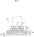
- Fig. 3 is a vertical sectional view showing a fusion device 100A which is a modification example of the fusion device 100 shown in Fig. 1 .
- the fusion device 100 in the present embodiment is a device that fuses a composite material (a first composite material) 200 and a composite material (a second composite material) 300, each of which includes a conductive reinforcement fiber and a thermoplastic resin, with each other.
- the fusion device 100 generates an electric current in the conductive reinforcement fibers by means of an inductive coil 10 so that the reinforcement fibers generate heat and thermoplastic resins included in the composite material 200 and the composite material 300 are heated to a temperature equal to or higher than the melting point thereof.
- the composite material 200 is formed in a flat shape by laminating three sheet-shaped composites 201, 202, and 203.
- Each of the composites 201, 202, and 203 includes a conductive fiber base material (for example, a carbon fiber) and a thermoplastic resin.
- the composite material 200 is densified in advance by pressurizing the thermoplastic resins to a temperature equal to or higher than the melting point thereof in a state where the three sheet-shaped composites 201, 202, and 203 are laminated in a flat shape and are pressurized.
- the composite material 300 is formed in a flat shape by laminating three sheet-shaped composites 301, 302, and 303.
- Each of the composites 301, 302, and 303 includes a conductive fiber base material (for example, a carbon fiber) and a thermoplastic resin.
- the composite material 300 is densified in advance by pressurizing the thermoplastic resins to a temperature equal to or higher than the melting point thereof in a state where the sheet-shaped composites 301, 302, and 303 are laminated in a flat shape and are pressurized.
- the composite material 200 obtained by laminating the three composites 201, 202, and 203 and the composite material 300 obtained by laminating the three composites 301, 302, and 303 are used.
- the number of composites may be any number equal to or larger than one.
- thermoplastic resins included in the composites 201, 202, and 203 and the composites 301, 302, and 303 include polyetheretherketone (PEEK), polyethylene terephthalate (PET), polybutylene terephthalate (PBT), nylon 6 (PA6), nylon 66 (PA66), polyphenylene sulfide (PPS), polyetherimide (PEI), and polyetherketoneketone (PEKK).
- PEEK polyetheretherketone
- PET polyethylene terephthalate
- PBT polybutylene terephthalate
- PA6 nylon 6
- PA66 nylon 66
- PPS polyphenylene sulfide
- PEI polyetherimide
- PEKK polyetherketoneketone
- the fusion device 100 of the present embodiment includes the inductive coil 10, a cooling pipe (a pipe body; a cooling unit) 20, a housing 30, and a pressurizing mechanism 40.
- the inductive coil 10 is a device that generates a magnetic force line in the vicinity thereof by means of an alternating current of a predetermined frequency supplied from an alternating power supply (not shown) and generates an electric current in a conductive reinforcement fiber disposed at a nearby position.
- the inductive coil 10 generates an electric current in a conductive reinforcement fiber such that the reinforcement fiber generates heat and a thermoplastic resin in the vicinity of the reinforcement fiber is heated to a temperature equal to or higher than the melting point thereof.
- the inductive coil 10 heats the thermoplastic resin included in the composite 203 to a temperature equal to or higher than the melting point by heating the composite material 200 and heats the thermoplastic resin included in the composite 301 to a temperature equal to or higher than the melting point by heating the composite material 300. Since the composite 203 and the composite 301 are disposed in a state of being in contact with each other, in a case where the thermoplastic resins included in the composites are heated to a temperature equal to or higher than the melting point, the thermoplastic resins are melted and integrated with each other and the composite 203 and the composite 301 are fused with each other.
- the inductive coil 10 may heat not only the thermoplastic resin included in the composite 203 that is in contact with the composite material 300 but also the thermoplastic resin included in the composite 202 adjacent to the composite 203 or the thermoplastic resin included in the composite 201 to a temperature equal to or higher than the melting point thereof.
- the inductive coil 10 may heat not only the thermoplastic resin included in the composite 301 that is in contact with the composite material 200 but also the thermoplastic resin included in the composite 302 adjacent to the composite 301 or the thermoplastic resin included in the composite 303 to a temperature equal to or higher than the melting point thereof.
- the inductive coil 10 may heat thermoplastic resins included in any number of composites including a composite of the composite material 200 that is in contact with the composite material 300 and a composite of the composite material 300 that is in contact with the composite material 200 to a temperature equal to or higher than the melting point thereof.
- the inductive coil 10 is disposed in a state of being fixed to an internal portion of the housing 30. Therefore, in a case where the housing 30 is brought into contact with an upper surface 200a of the composite material 200, the inductive coil 10 enters a state of being disposed close to the composite material 200. As shown in Fig. 2 , the inductive coil 10 is disposed to extend around the center of the housing 30 in the vicinity of a pressurization surface 31 of the housing 30.
- inductive coil 10 In a case where the inductive coil 10 is fixed to a lower portion (a position closer to the upper surface 200a than the pressurizing mechanism 40) of the internal portion of the housing 30, electric power required to heat the composite material 200 and the composite material 300 to a temperature equal to or higher than the melting point thereof can be lowered in comparison with a case where the inductive coil 10 is fixed to an upper portion (a position closer to the pressurizing mechanism 40 than the upper surface 200a) of the internal portion of the housing 30. This is because an electric current can be generated in the conductive reinforcement fibers with a smaller amount of electric current since a distance between a position at which the inductive coil 10 is disposed and a position where the composite 203 and the composite 301 are fused with each other is short.
- the cooling pipe 20 cools the pressurization surface 31 of the housing 30 and is a pipe body through which a cooling medium (for example, water) flows.
- the cooling pipe 20 is formed of a resin material such as nylon, silicon, or fluororesin, for example.
- the cooling pipe 20 is disposed in a state of being fixed to the internal portion of the housing 30. Therefore, in a case where the housing 30 is brought into contact with the upper surface 200a of the composite material 200, the cooling pipe 20 enters a state of being disposed close to the composite material 200.
- the cooling pipe 20 is disposed to extend around the center of the housing 30 in the vicinity of the pressurization surface 31 of the housing 30.
- a region 10a of the inductive coil 10 that is guided to an outer side from the center overlaps the inductive coil 10 and the cooling pipe 20 disposed closer to an outer peripheral side than the center and a region 20a of the cooling pipe 20 that is guided to an outer side from the center overlaps the inductive coil 10 and the cooling pipe 20 disposed closer to the outer peripheral side than the center.
- another configuration may also be adopted.
- a configuration in which the inductive coil 10 and the cooling pipe 20 are disposed on the same plane not to overlap each other may also be adopted.
- both of the inductive coil 10 and the cooling pipe 20 are disposed to be separated from the pressurization surface 31 and the composite material 200 by the same distance.
- the inductive coil 10 and the cooling pipe 20 may be disposed as in a modification example shown in Fig. 3 .
- the cooling pipe 20 is disposed closer to the pressurization surface 31 than the inductive coil 10.
- the cooling pipe 20 is disposed closer to the upper surface 200a of the composite material 200 than the inductive coil 10.
- heat transfer properties from the cooling pipe 20 to the pressurization surface 31 are improved and cooling performance is improved in comparison with a case where the cooling pipe 20 is disposed at an upper portion of the internal portion of the housing 30 (the position closer to the pressurizing mechanism 40 than the upper surface 200a).
- both of the distance from the pressurization surface 31 to the inductive coil 10 and the distance from the pressurization surface 31 to the cooling pipe 20 are the length L1.
- the distance from the pressurization surface 31 to the inductive coil 10 is longer than the distance from the pressurization surface 31 to the cooling pipe 20. Since the inductive coil 10 is not present at the lower portion (the position closer to the upper surface 200a than the pressurizing mechanism 40) of the internal portion of the housing 30, the cooling pipe 20 can be disposed over a wide range at a position close to the pressurization surface 31. Therefore, the cooling performance of the cooling pipe 20 cooling the pressurization surface 31 and the upper surface 200a of the composite material 200 is improved.
- the housing 30 is a structure in which the inductive coil 10 and the cooling pipe 20 are disposed and is formed of a block-shaped resin material (for example, a phenol resin).
- the housing 30 is formed in a block-like shape by disposing the inductive coil 10 and the cooling pipe 20 shown in Fig. 2 in a molding tool (not shown), pouring a resin material heated to be lowered in viscosity into the molding tool, and cooling the molding tool.
- the housing 30 includes the pressurization surface 31 that is disposed between the inductive coil 10 and the composite material 200 in a state of being in contact with the composite material 200. Since the pressurization surface 31 is disposed between the inductive coil 10 and the composite material 200, a position (a fusion position) where the inductive coil 10 heats the composite material 200 and the composite material 300 can be directly pressurized.
- the pressurizing mechanism 40 is a device that pressurizes the fusion device 100, which is disposed above the composite material 200 and the composite material 300 installed on an installation surface Su, along a pressurizing direction PD toward the installation surface Su.
- the installation surface Su is a surface on which the composite material 200 and the composite material 300 are installed in order to fuse the composite material 200 and the composite material 300 with each other by means of the fusion device 100.
- the pressurizing mechanism 40 can switch between a pressurization state shown in Fig. 1 in which the pressurizing mechanism 40 is in contact with the housing 30 and a non-pressurization state in which the pressurizing mechanism 40 is separated from the housing 30.
- Fig. 4 is a flowchart showing a fusion method according to the embodiment.
- step S101 the housing 30 of the fusion device 100 is installed at a desired position on the composite material 200 that overlaps the composite material 300 provided on the installation surface Su.
- step S102 a cooling medium is caused to flow through the cooling pipe 20 disposed in the housing 30 to start the cooling of the pressurization surface 31 and the cooling of the upper surface 200a of the composite material 200 via the pressurization surface 31.
- the cooling of the housing 30 that is performed by means of the cooling pipe 20 may be started before the housing 30 is installed on the composite material 200 in step S101.
- step S103 an operation of bringing the pressurizing mechanism 40 into contact with the housing 30 and pressurizing the composite material 200 toward the installation surface Su along the pressurizing direction PD is started.
- step S104 supply of an alternating current from the alternating power supply (not shown) to the inductive coil 10 is started to start the heating of the composite material 200 and the composite material 300 that is performed by means of the inductive coil 10.
- step S105 the supply of the alternating current to the inductive coil 10 is stopped when the heating of the composite material 200 and the composite material 300 that is performed by means of the inductive coil 10 is performed for a sufficient time to fuse the composite material 200 and the composite material 300 with each other. Accordingly, the heating of the composite material 200 and the composite material 300 that is performed by the inductive coil 10 is stopped.
- step S106 when a predetermined time required for the temperature of the thermoplastic resins of the composite material 200 and the composite material 300 to be lowered to a temperature sufficiently lower than the melting point thereof elapses after the heating of the composite material 200 and the composite material 300 that is performed by the inductive coil 10 is stopped, pressurization performed by the pressurizing mechanism 40 is stopped.
- step S107 since the fusion of the composite material 200 and the composite material 300 at a position where the housing 30 is installed is finished, the housing 30 is removed from the position. After the housing 30 is removed, processing in step S101 is started again and the housing 30 is installed at another position where fusion has not been performed. By repeating the above-described processing, fusion can be performed on desired positions of the composite material 200 and the composite material 300.
- a fusion device 100B according to a second embodiment of the present disclosure will be described with reference to the drawings.
- Fig. 5 is a vertical sectional view showing the fusion device 100B according to the present embodiment.
- the present embodiment is a modification example of the first embodiment, is the same as the first embodiment except for a case particularly described below, and the description thereof will be omitted below.
- the cooling medium is caused to flow through the cooling pipe 20 disposed inside the housing 30 formed of a block-shaped resin material so as to cool the upper surface 200a of the composite material 200 via the pressurization surface 31 of the housing 30.
- the cooling medium is supplied into and discharged from a space inside the housing 30B formed in a box shape so as to cool the upper surface 200a of the composite material 200 via the pressurization surface 31 of the housing 30.
- the housing 30B of the fusion device 100B of the present embodiment is formed in a box shape such that a space S1 in which the inductive coil 10 is disposed is formed therein.
- the fusion device 100B includes a cooling unit 20B that causes the cooling medium to flow into an inlet 21B communicating with the space S1 and causes the cooling medium to be discharged through an outlet 22B communicating with the space S1.
- the cooling unit 20B circulates the cooling medium by supplying the cooling medium into the space S1 through the inlet 21B after adjusting the temperature of the cooling medium discharged through the outlet 22B to a predetermined temperature.
- the housing 30B since the cooling medium circulates in the box-shaped housing 30B, the housing 30B can be maintained at a desired temperature. Therefore, the upper surface 200a of the composite material 200 can be maintained at a desired temperature via the pressurization surface 31 of the housing 30B.
- a fusion device 100C according to a third embodiment of the present disclosure will be described with reference to the drawings.
- Fig. 6 is a vertical sectional view showing the fusion device 100C according to the present embodiment.
- Fig. 7 is a cross-sectional view taken along line I-I which shows the fusion device 100C shown in Fig. 6 as seen along arrows.
- the present embodiment is a modification example of the first embodiment, is the same as the first embodiment except for a case particularly described below, and the description thereof will be omitted below.
- the cooling medium is caused to flow through the cooling pipe 20 disposed inside the housing 30 formed of a block-shaped resin material so as to cool the upper surface 200a of the composite material 200 via the pressurization surface 31 of the housing 30.
- a communication flow path 34C is provided in the housing 30C formed of a block-shaped resin material and the cooling medium is caused to flow through the communication flow path 34C so as to cool the upper surface 200a of the composite material 200 via the pressurization surface 31 of the housing 30C.
- the housing 30C of the fusion device 100C of the present embodiment is provided with an inlet 32C into which the cooling medium flows and an outlet 33C through which the cooling medium is discharged.
- the housing 30C is further provided with the communication flow path 34C through which the inlet 32C and the outlet 33C communicate with each other.
- the fusion device 100C includes a cooling unit 20C that causes the cooling medium to flow into the inlet 32C and causes the cooling medium to be discharged through the outlet 33C.
- the cooling unit 20C circulates the cooling medium in the housing 30C by supplying the cooling medium into the communication flow path 34C through the inlet 32C after adjusting the temperature of the cooling medium discharged through the outlet 33C to a predetermined temperature.
- the housing 30C since the cooling medium circulates in the housing 30C formed of a block-shaped resin material, the housing 30C can be maintained at a desired temperature. Therefore, the upper surface 200a of the composite material 200 can be maintained at a desired temperature via the pressurization surface 31 of the housing 30C.
- a fusion device 100D according to a fourth embodiment of the present disclosure will be described with reference to the drawings.
- Fig. 8 is a vertical sectional view showing the fusion device 100D according to the present embodiment.
- the present embodiment is a modification example of the first embodiment, is the same as the first embodiment except for a case particularly described below, and the description thereof will be omitted below.
- the cooling medium is caused to flow through the cooling pipe 20 disposed inside the housing 30 formed of a block-shaped resin material so as to cool the upper surface 200a of the composite material 200 via the pressurization surface 31 of the housing 30.
- a cooling gas is jetted toward a housing 30D to cool the pressurization surface 31.
- the fusion device 100D of the present embodiment includes a jetting mechanism (a cooling unit) 20D that jets a cooling gas (for example, air) toward an upper surface of the housing 30D.
- the jetting mechanism 20D jets the cooling gas toward the upper surface of the housing 30D to lower the temperature of the upper surface of the housing 30D formed of a block-shaped resin material.
- the temperature of the upper surface of the housing 30D is lowered, the temperature is transmitted to the pressurization surface 31, so that the pressurization surface 31 is cooled.
- the upper surface 200a of the composite material 200 in contact with the pressurization surface 31 is also cooled.
- the housing 30D is a relatively simple mechanism provided with only the inductive coil 10 disposed therein and the pressurization surface 31 of the housing 30D and the upper surface 200a of the composite material 200 can be cooled by means of the jetting mechanism 20D provided separately from the housing 30.
- a fusion device 100E as shown in Fig. 9 may also be adopted.
- the fusion device 100E shown in Fig. 9 includes a jetting mechanism (a second cooling mechanism) 20E in addition to the jetting mechanism (a first cooling mechanism) 20D.
- the jetting mechanism 20E is a mechanism that jets the cooling gas toward an adjacent region adjacent to a contact region of the composite material 200 where the composite material 200 comes into contact with the pressurization surface 31, to cool the adjacent region.
- a fusion device 100F according to a fifth embodiment of the present disclosure will be described with reference to the drawings.
- Fig. 10 is a vertical sectional view showing the fusion device 100F according to the present embodiment.
- Fig. 11 is a front view showing the fusion device 100F shown in Fig. 10 .
- Fig. 12 is a view showing the fusion device 100F shown in Fig. 11 as seen from the pressurization surface 31 side.
- the present embodiment is a modification example of the fourth embodiment, is the same as the fourth embodiment except for a case particularly described below, and the description thereof will be omitted below.
- flow paths through which a cooling gas jetted from the jetting mechanism 20D flows are provided in a housing 30F formed of a block-shaped resin material, so that the upper surface 200a of the composite material 200 can be cooled at the position of the pressurization surface 31.
- the cooling pipe 20 in the first embodiment is provided in the housing 30F to further improve the cooling effect.
- a pair of introduction flow paths 31F, a communication flow path 32F, a communication flow path 33F, and a communication flow path 34F are formed in the housing 30F of the present embodiment.
- the cooling gas introduced from the jetting mechanism 20D into the pair of introduction flow paths 31F cools the upper surface 200a of the composite material 200 when passing through the communication flow path 32F, the communication flow path 33F, and the communication flow path 34F.
- the pair of introduction flow paths 31F is a pair of flow paths that guides the cooling gas jetted from the jetting mechanism 20D and extends in a vertical direction. Lower ends of the pair of introduction flow paths 31F communicate with respective flow paths at a position at which the communication flow path 32F and the communication flow path 33F intersect each other and a position at which the communication flow path 32F and the communication flow path 33F intersect each other.
- the communication flow path 32F is a flow path that communicates with the introduction flow paths 31F, extends in a horizontal direction, and penetrates the housing 30F. Through the communication flow path 32F, a cooling gas introduced from the introduction flow paths 31F flows in the horizontal direction along the upper surface 200a of the composite material 200.
- the communication flow path 33F is a flow path that communicates with the introduction flow path 31F and extends in a horizontal direction. As shown in Fig. 12 , the communication flow path 33F is a flow path that extends in a direction orthogonal to the communication flow path 32F.
- the communication flow path 34F is a flow path that communicates with the introduction flow path 31F and extends in the horizontal direction. As shown in Fig. 12 , the communication flow path 34F is a flow path that extends in the direction orthogonal to the communication flow path 32F.
- a surface of the housing 30F of the present embodiment that comes into contact with the upper surface 200a of the composite material 200 includes a region in which the communication flow paths 32F, 33F, and 34F are formed and that does not come into contact with the upper surface 200a of the composite material 200 and a region in which the communication flow paths 32F, 33F, and 34F are not formed and that comes into contact with the upper surface 200a of the composite material 200.
- the region that comes into contact with the upper surface 200a of the composite material 200 is the pressurization surface 31.
- the fusion device 100F of the present embodiment it is possible to protect the upper surface 200a of the composite material 200 close to the inductive coil 10 from damage caused by heat by appropriately cooling a region adjacent to the pressurization surface 31 while pressurizing, by means of the pressurization surface 31 of the housing 30F, a region of the composite material 200 that is heated by the inductive coil 10.
- the fusion device described in the above-described embodiment is understood as follows, for example.
- a fusion device (100) fuses a first composite material (200) and a second composite material (300), each of which includes a conductive reinforcement fiber and a thermoplastic resin, with each other and the fusion device includes an inductive coil (10) that is disposed close to the first composite material, generates an electric current in the reinforcement fiber included in the first composite material to cause the first composite material to generate heat, and generates an electric current in the reinforcement fiber included in the second composite material to cause the second composite material to generate heat, a housing (30) that includes a pressurization surface (31) disposed between the inductive coil and the first composite material in a state of being in contact with the first composite material, and a cooling unit (20) that cools the pressurization surface.
- the first composite material is cooled via the pressurization surface that is disposed in a state of being in contact with the first composite material disposed close to the inductive coil. Since a cooling gas such as air does not need to be provided between the inductive coil and a surface of the first composite material, the inductive coil can be disposed at a position close to the surface of the first composite material. Accordingly, a current value required to increase the temperature of a fusion position between the first composite material and the second composite material to a temperature equal to or higher than the melting point of the thermoplastic resins is not high. Therefore, it is possible to protect a surface of a composite material close to the inductive coil from damage caused by heat without increasing electric power required for fusion.
- the pressurization surface is disposed between the inductive coil and the first composite material in a state of being in contact with the first composite material. Therefore, it is possible to achieve a favorable fusion state by pressurizing the first composite material via the pressurization surface so as to pressurize a heated portion at the same time the first composite material is heated by the inductive coil.
- the cooling unit is a pipe body through which a cooling medium flows and the housing is formed of a block-shaped resin material in which the inductive coil and the pipe body are disposed.
- the housing formed of the block-shaped resin material is cooled by the cooling medium flowing through the pipe body, so that the pressurization surface which is a portion of the housing is cooled. Accordingly, the first composite that is in contact with the pressurization surface can be appropriately cooled.
- the pipe body is disposed at a position closer to the pressurization surface than the inductive coil.
- the pipe body is in a state of being close to the pressurization surface and thus the efficiency of cooling that is performed with respect to the pressurization surface via the cooling medium flowing through the pipe body and cooling that is performed with respect to the first composite material being in contact with the pressurization surface is improved.
- the pipe body is disposed at a position such that a distance from the pressurization surface to the inductive coil and a distance from the pressurization surface to the pipe body are the same as each other.
- the housing is formed in a box shape such that a space (S1) in which the inductive coil is disposed is formed therein and the cooling unit is a mechanism that causes a cooling medium to flow into an inlet (21B) communicating with the space and causes the cooling medium to be discharged through an outlet (22B) communicating with the space.
- the box-shaped housing forming the space in which the inductive coil is disposed is cooled by the cooling medium flowing through the space, so that the pressurization surface which is a portion of the housing is cooled. Accordingly, the first composite that is in contact with the pressurization surface can be appropriately cooled.
- the housing is formed of a block-shaped resin material in which the inductive coil is installed and that includes an inlet (32C) into which a cooling medium flows, an outlet (33C) through which the cooling medium is discharged, and a communication flow path (34C) through which the inlet and the outlet communicate with each other and the cooling unit is a mechanism that causes the cooling medium to flow into the inlet and causes the cooling medium to be discharged through the outlet.
- the housing formed of the block-shaped resin material is cooled by the cooling medium flowing through the communication flow path included in the housing, so that the pressurization surface which is a portion of the housing is cooled. Accordingly, the first composite that is in contact with the pressurization surface can be appropriately cooled.
- the cooling unit is a mechanism that jets a cooling gas toward the housing to cool the pressurization surface.
- the cooling gas is jetted toward the housing so that the pressurization surface which is a portion of the housing is cooled and thus it is possible to appropriately cool the first composite material in contact with the pressurization surface.
- the cooling unit includes a first cooling mechanism (20D) that jets the cooling gas toward the housing to cool the pressurization surface and a second cooling mechanism (20E) that jets the cooling gas toward an adjacent region adjacent to a contact region of the first composite material where the first composite material comes into contact with the pressurization surface, to cool the adjacent region.
- the contact region of the first composite material where the first composite material comes into contact with the pressurization surface is cooled by the first cooling mechanism and the adjacent region adjacent to the contact region is cooled by the second cooling mechanism.
- the housing is formed of a block-shaped resin material in which the inductive coil is disposed and an introduction flow path (31F) that guides the cooling gas jetted from the cooling unit and a communication flow path (32F) through which the cooling gas introduced from the introduction flow path flows along the first composite material disposed in a state of being in contact with the pressurization surface are formed in the housing.
- the fusion device of the present disclosure it is possible to protect the upper surface of the first composite material close to the inductive coil from damage caused by heat by appropriately cooling a region adjacent to the pressurization surface while pressurizing, by means of the pressurization surface of the housing, a region of the first composite material that is heated by the inductive coil.
- a fusion method is a fusion method of fusing a first composite material and a second composite material, each of which includes a conductive reinforcement fiber and a thermoplastic resin, with each other, the method including a cooling step of cooling a housing that includes a pressurization surface disposed in a state of being in contact with the first composite material; a pressurizing step of pressurizing the first composite material via the pressurization surface in a state where the pressurization surface is in contact with the first composite material; and a heating step of driving an inductive coil that is disposed with the pressurization surface interposed between the first composite material and the inductive coil, generating an electric current in the reinforcement fiber included in the first composite material to cause the first composite material to generate heat, and generating an electric current in the reinforcement fiber included in the second composite material to heat the second composite material after the pressurization surface is cooled in the cooling step and the first composite material is pressurized in the pressurizing step.
- the first composite material is cooled via the pressurization surface that is disposed in a state of being in contact with the first composite material disposed close to the inductive coil. Since a cooling gas such as air does not need to be provided between the inductive coil and a surface of the first composite material, the inductive coil can be disposed at a position close to the surface of the first composite material. Accordingly, a current value required to increase the temperature of a fusion position between the first composite material and the second composite material to a temperature equal to or higher than the melting point of the thermoplastic resins is not high. Therefore, it is possible to protect a surface of a composite material close to the inductive coil from damage caused by heat without increasing electric power required for fusion.
- the pressurization surface is disposed between the inductive coil and the first composite material in a state of being in contact with the first composite material. Therefore, it is possible to achieve a favorable fusion state by pressurizing the first composite material via the pressurization surface in the pressurizing step so as to pressurize a heated portion at the same time the first composite material is heated by the inductive coil.
Landscapes
- Engineering & Computer Science (AREA)
- Mechanical Engineering (AREA)
- Physics & Mathematics (AREA)
- Thermal Sciences (AREA)
- High Energy & Nuclear Physics (AREA)
- Plasma & Fusion (AREA)
- Lining Or Joining Of Plastics Or The Like (AREA)
Abstract
Description
- The present disclosure relates to a fusion device that fuses a first composite material and a second composite material, each of which includes a conductive reinforcement fiber and a thermoplastic resin, with each other and a fusion method.
- In the related art, there is known a technique in which a plurality of composite materials including carbon fibers and thermoplastic resins are heated by means of an inductive coil so that the thermoplastic resin is melted and the plurality of composite materials are fused with each other (for example, refer to NPL 1). NPL 1 discloses a technique in which air is jetted to a space between the inductive coil and a surface of a composite material to decrease the temperature of the surface of the composite material and to protect the surface of the composite material close to the inductive coil from damage caused by heat.
- [NPL 1] M.Duhovic et al. "ADVANCED 3D FINITE ELEMENT SIMULATION OF THERMOPLASTIC CARBON FIBER COMPOSITE INDUCTION WELDING" 16th EUROPEAN CONFERENCE ON COMPOSITE MATERIALS, June 2014
- However, in the case of NPL 1, it is necessary to hold the inductive coil at a position separated from the surface of the composite material in order to cause the air to flow through the space between the inductive coil and the surface of the composite material. In a case where a distance between the surface of the composite material and the inductive coil is large, a magnetic field applied by the inductive coil is weakened in proportion to the distance. Therefore, a current value that is required to increase the temperature of a fusion position where the composite material close to the inductive coil and another composite material are fused with each other to a temperature equal to or higher than the melting point of the thermoplastic resins becomes high, which increases electric power required for fusion.
- To appropriately fuse the composite materials, of which the thermoplastic resins have been heated by the inductive coil to a temperature equal to or higher than the melting point thereof, with each other, it is necessary to appropriately pressurize the composite materials to each other with the thermoplastic resins heated to the temperature equal to or higher than the melting point thereof. However, in the case of NPL 1, air is caused to flow through the space between the inductive coil and the surface of the composite material. Therefore, it is not possible to pressurize the composite materials toward the fusion position at a position where the composite materials are heated by the inductive coil. In the case of NPL 1, the composite materials are pressurized by a roller at a position to which the composite materials are transported from a position where the composite materials are heated by the inductive coil. Therefore, the temperature of the thermoplastic resins is decreased to a temperature lower than the temperature thereof at the position where the composite materials are heated by the inductive coil and thus a favorable fusion state may not be achieved.
- The present disclosure has been made in view of such circumstances and an object thereof is to provide a fusion device and a fusion method with which it is possible to protect a surface of a composite material close to an inductive coil from damage caused by heat and to achieve an appropriate fusion state without an increase in electric power required for fusion.
- According to an aspect of the present disclosure, there is provided a fusion device which fuses a first composite material and a second composite material, each of which includes a conductive reinforcement fiber and a thermoplastic resin, with each other. The fusion device includes an inductive coil that is disposed close to the first composite material, generates an electric current in the reinforcement fiber included in the first composite material to cause the first composite material to generate heat, and generates an electric current in the reinforcement fiber included in the second composite material to cause the second composite material to generate heat, a housing that includes a pressurization surface disposed between the inductive coil and the first composite material in a state of being in contact with the first composite material, and a cooling unit that cools the pressurization surface.
- According to an aspect of the present disclosure, there is provided a fusion method of fusing a first composite material and a second composite material, each of which includes a conductive reinforcement fiber and a thermoplastic resin, with each other. The fusion method includes a cooling step of cooling a housing that includes a pressurization surface disposed in a state of being in contact with the first composite material, a pressurizing step of pressurizing the first composite material via the pressurization surface in a state where the pressurization surface is in contact with the first composite material, and a heating step of driving an inductive coil that is disposed with the pressurization surface interposed between the first composite material and the inductive coil, generating an electric current in the reinforcement fiber included in the first composite material to cause the first composite material to generate heat, and generating an electric current in the reinforcement fiber included in the second composite material to heat the second composite material after the pressurization surface is cooled in the cooling step and the first composite material is pressurized in the pressurizing step.
- According to the aspects of the present disclosure, it is possible to provide a fusion device and a fusion method with which it is possible to protect a surface of a composite material close to an inductive coil from damage caused by heat and to achieve an appropriate fusion state without an increase in electric power required for fusion.
-
-
Fig. 1 is a vertical sectional view showing a fusion device according to a first embodiment of the present disclosure. -
Fig. 2 is a perspective view showing the fusion device shown inFig. 1 . -
Fig. 3 is a vertical sectional view showing a fusion device which is a modification example of the fusion device shown inFig. 1 . -
Fig. 4 is a flowchart showing a fusion method according to the first embodiment. -
Fig. 5 is a vertical sectional view showing a fusion device according to a second embodiment. -
Fig. 6 is a vertical sectional view showing a fusion device according to a third embodiment. -
Fig. 7 is a cross-sectional view taken along line I-I which shows the fusion device shown inFig. 6 as seen along arrows. -
Fig. 8 is a vertical sectional view showing a fusion device according to a fourth embodiment. -
Fig. 9 is a vertical sectional view showing a modification example of the fusion device shown inFig. 8 . -
Fig. 10 is a vertical sectional view showing a fusion device according to a fifth embodiment. -
Fig. 11 is a front view showing the fusion device shown inFig. 10 . -
Fig. 12 is a view showing the fusion device shown inFig. 11 as seen from a pressurization surface side. Description of Embodiments - Hereinafter, a
fusion device 100 according to a first embodiment of the present disclosure and a fusion method in which thefusion device 100 is used will be described with reference to the drawings.Fig. 1 is a vertical sectional view showing thefusion device 100 according to the first embodiment of the present disclosure.Fig. 2 is a perspective view showing thefusion device 100 shown inFig. 1 .Fig. 3 is a vertical sectional view showing afusion device 100A which is a modification example of thefusion device 100 shown inFig. 1 . - The
fusion device 100 in the present embodiment is a device that fuses a composite material (a first composite material) 200 and a composite material (a second composite material) 300, each of which includes a conductive reinforcement fiber and a thermoplastic resin, with each other. Thefusion device 100 generates an electric current in the conductive reinforcement fibers by means of aninductive coil 10 so that the reinforcement fibers generate heat and thermoplastic resins included in thecomposite material 200 and thecomposite material 300 are heated to a temperature equal to or higher than the melting point thereof. - As shown in
Fig. 1 , thecomposite material 200 is formed in a flat shape by laminating three sheet-shaped composites composites composite material 200 is densified in advance by pressurizing the thermoplastic resins to a temperature equal to or higher than the melting point thereof in a state where the three sheet-shaped composites - As shown in
Fig. 1 , thecomposite material 300 is formed in a flat shape by laminating three sheet-shaped composites composites composite material 300 is densified in advance by pressurizing the thermoplastic resins to a temperature equal to or higher than the melting point thereof in a state where the sheet-shaped composites - In the present embodiment, the
composite material 200 obtained by laminating the threecomposites composite material 300 obtained by laminating the threecomposites - Examples of the thermoplastic resins included in the
composites composites - As shown in
Fig. 1 , thefusion device 100 of the present embodiment includes theinductive coil 10, a cooling pipe (a pipe body; a cooling unit) 20, ahousing 30, and apressurizing mechanism 40. - The
inductive coil 10 is a device that generates a magnetic force line in the vicinity thereof by means of an alternating current of a predetermined frequency supplied from an alternating power supply (not shown) and generates an electric current in a conductive reinforcement fiber disposed at a nearby position. Theinductive coil 10 generates an electric current in a conductive reinforcement fiber such that the reinforcement fiber generates heat and a thermoplastic resin in the vicinity of the reinforcement fiber is heated to a temperature equal to or higher than the melting point thereof. - The
inductive coil 10 heats the thermoplastic resin included in thecomposite 203 to a temperature equal to or higher than the melting point by heating thecomposite material 200 and heats the thermoplastic resin included in thecomposite 301 to a temperature equal to or higher than the melting point by heating thecomposite material 300. Since thecomposite 203 and thecomposite 301 are disposed in a state of being in contact with each other, in a case where the thermoplastic resins included in the composites are heated to a temperature equal to or higher than the melting point, the thermoplastic resins are melted and integrated with each other and thecomposite 203 and thecomposite 301 are fused with each other. - When the
inductive coil 10 heats thecomposite material 200, theinductive coil 10 may heat not only the thermoplastic resin included in thecomposite 203 that is in contact with thecomposite material 300 but also the thermoplastic resin included in thecomposite 202 adjacent to thecomposite 203 or the thermoplastic resin included in thecomposite 201 to a temperature equal to or higher than the melting point thereof. In addition, when theinductive coil 10 heats thecomposite material 300, theinductive coil 10 may heat not only the thermoplastic resin included in thecomposite 301 that is in contact with thecomposite material 200 but also the thermoplastic resin included in thecomposite 302 adjacent to thecomposite 301 or the thermoplastic resin included in thecomposite 303 to a temperature equal to or higher than the melting point thereof. That is, in a case where each of thecomposite material 200 and thecomposite material 300 is composed of a plurality of composites, theinductive coil 10 may heat thermoplastic resins included in any number of composites including a composite of thecomposite material 200 that is in contact with thecomposite material 300 and a composite of thecomposite material 300 that is in contact with thecomposite material 200 to a temperature equal to or higher than the melting point thereof. - The
inductive coil 10 is disposed in a state of being fixed to an internal portion of thehousing 30. Therefore, in a case where thehousing 30 is brought into contact with anupper surface 200a of thecomposite material 200, theinductive coil 10 enters a state of being disposed close to thecomposite material 200. As shown inFig. 2 , theinductive coil 10 is disposed to extend around the center of thehousing 30 in the vicinity of apressurization surface 31 of thehousing 30. - In a case where the
inductive coil 10 is fixed to a lower portion (a position closer to theupper surface 200a than the pressurizing mechanism 40) of the internal portion of thehousing 30, electric power required to heat thecomposite material 200 and thecomposite material 300 to a temperature equal to or higher than the melting point thereof can be lowered in comparison with a case where theinductive coil 10 is fixed to an upper portion (a position closer to thepressurizing mechanism 40 than theupper surface 200a) of the internal portion of thehousing 30. This is because an electric current can be generated in the conductive reinforcement fibers with a smaller amount of electric current since a distance between a position at which theinductive coil 10 is disposed and a position where the composite 203 and the composite 301 are fused with each other is short. - The cooling
pipe 20 cools thepressurization surface 31 of thehousing 30 and is a pipe body through which a cooling medium (for example, water) flows. The coolingpipe 20 is formed of a resin material such as nylon, silicon, or fluororesin, for example. As shown inFig. 2 , the coolingpipe 20 is disposed in a state of being fixed to the internal portion of thehousing 30. Therefore, in a case where thehousing 30 is brought into contact with theupper surface 200a of thecomposite material 200, the coolingpipe 20 enters a state of being disposed close to thecomposite material 200. As shown inFig. 2 , the coolingpipe 20 is disposed to extend around the center of thehousing 30 in the vicinity of thepressurization surface 31 of thehousing 30. - In a case where the cooling
pipe 20 is fixed to a lower portion (a position closer to theupper surface 200a than the pressurizing mechanism 40) of the internal portion of thehousing 30, performance for cooling theupper surface 200a of thecomposite material 200 via thepressurization surface 31 is improved in comparison with a case where the coolingpipe 20 is fixed to an upper portion (a position closer to thepressurizing mechanism 40 than theupper surface 200a) of the internal portion of thehousing 30. This is because heat transfer properties from the coolingpipe 20 to thepressurization surface 31 are improved since a distance between a position at which thecooling pipe 20 is disposed and a position at which thepressurization surface 31 is disposed is short. - In an example shown in
Fig. 2 , aregion 10a of theinductive coil 10 that is guided to an outer side from the center overlaps theinductive coil 10 and the coolingpipe 20 disposed closer to an outer peripheral side than the center and aregion 20a of the coolingpipe 20 that is guided to an outer side from the center overlaps theinductive coil 10 and the coolingpipe 20 disposed closer to the outer peripheral side than the center. However, another configuration may also be adopted. For example, a configuration in which theinductive coil 10 and the coolingpipe 20 are disposed on the same plane not to overlap each other may also be adopted. - As shown in
Fig. 1 , in the case of thefusion device 100 of the present embodiment, both of theinductive coil 10 and the coolingpipe 20 are disposed to be separated from thepressurization surface 31 and thecomposite material 200 by the same distance. As shown inFig. 1 , a distance from thepressurization surface 31 and thecomposite material 200 to a position where acentral axis 10b of theinductive coil 10 is disposed and is a length L1. In addition, a distance from thepressurization surface 31 and thecomposite material 200 to a position where acentral axis 20b of the coolingpipe 20 is disposed and is the length L1. Accordingly, it is possible to achieve both of the heating performance of theinductive coil 10 heating thecomposite material 200 and thecomposite material 300 and the cooling performance of the coolingpipe 20 cooling theupper surface 200a of thecomposite material 200 via thepressurization surface 31. - Note that the
inductive coil 10 and the coolingpipe 20 may be disposed as in a modification example shown inFig. 3 . In ahousing 30A that afusion device 100A according to the modification example shown inFig. 3 includes, the coolingpipe 20 is disposed closer to thepressurization surface 31 than theinductive coil 10. As shown inFig. 3 , in a case where thepressurization surface 31 is disposed to come into contact with theupper surface 200a of thecomposite material 200, the coolingpipe 20 is disposed closer to theupper surface 200a of thecomposite material 200 than theinductive coil 10. Therefore, heat transfer properties from the coolingpipe 20 to thepressurization surface 31 are improved and cooling performance is improved in comparison with a case where the coolingpipe 20 is disposed at an upper portion of the internal portion of the housing 30 (the position closer to thepressurizing mechanism 40 than theupper surface 200a). - In an example shown in
Fig. 1 , both of the distance from thepressurization surface 31 to theinductive coil 10 and the distance from thepressurization surface 31 to the coolingpipe 20 are the length L1. However, in the case of the modification example shown inFig. 3 , the distance from thepressurization surface 31 to theinductive coil 10 is longer than the distance from thepressurization surface 31 to the coolingpipe 20. Since theinductive coil 10 is not present at the lower portion (the position closer to theupper surface 200a than the pressurizing mechanism 40) of the internal portion of thehousing 30, the coolingpipe 20 can be disposed over a wide range at a position close to thepressurization surface 31. Therefore, the cooling performance of the coolingpipe 20 cooling thepressurization surface 31 and theupper surface 200a of thecomposite material 200 is improved. - The
housing 30 is a structure in which theinductive coil 10 and the coolingpipe 20 are disposed and is formed of a block-shaped resin material (for example, a phenol resin). Thehousing 30 is formed in a block-like shape by disposing theinductive coil 10 and the coolingpipe 20 shown inFig. 2 in a molding tool (not shown), pouring a resin material heated to be lowered in viscosity into the molding tool, and cooling the molding tool. - As shown in
Fig. 1 , thehousing 30 includes thepressurization surface 31 that is disposed between theinductive coil 10 and thecomposite material 200 in a state of being in contact with thecomposite material 200. Since thepressurization surface 31 is disposed between theinductive coil 10 and thecomposite material 200, a position (a fusion position) where theinductive coil 10 heats thecomposite material 200 and thecomposite material 300 can be directly pressurized. - The
pressurizing mechanism 40 is a device that pressurizes thefusion device 100, which is disposed above thecomposite material 200 and thecomposite material 300 installed on an installation surface Su, along a pressurizing direction PD toward the installation surface Su. The installation surface Su is a surface on which thecomposite material 200 and thecomposite material 300 are installed in order to fuse thecomposite material 200 and thecomposite material 300 with each other by means of thefusion device 100. Thepressurizing mechanism 40 can switch between a pressurization state shown inFig. 1 in which thepressurizing mechanism 40 is in contact with thehousing 30 and a non-pressurization state in which thepressurizing mechanism 40 is separated from thehousing 30. - It is possible to fuse the
composite material 200 and thecomposite material 300 with each other in a state where thecomposite material 200 and thecomposite material 300 are in close contact with each other by causing theinductive coil 10 to heat thecomposite material 200 and thecomposite material 300 with thepressurizing mechanism 40 performing pressurization. In addition, it is possible to maintain a state where thecomposite material 200 and thecomposite material 300 are densified by causing thepressurizing mechanism 40 to continuously perform the pressurization when thecomposite material 200 and thecomposite material 300 are cooled from a temperature equal to or higher than the melting point thereof to a temperature lower than the melting point. - Next, a fusion method that is performed by using the
fusion device 100 of the present embodiment will be described with reference toFig. 4. Fig. 4 is a flowchart showing a fusion method according to the embodiment. - In step S101, the
housing 30 of thefusion device 100 is installed at a desired position on thecomposite material 200 that overlaps thecomposite material 300 provided on the installation surface Su. - In step S102, a cooling medium is caused to flow through the cooling
pipe 20 disposed in thehousing 30 to start the cooling of thepressurization surface 31 and the cooling of theupper surface 200a of thecomposite material 200 via thepressurization surface 31. Note that the cooling of thehousing 30 that is performed by means of the coolingpipe 20 may be started before thehousing 30 is installed on thecomposite material 200 in step S101. - In step S103, an operation of bringing the
pressurizing mechanism 40 into contact with thehousing 30 and pressurizing thecomposite material 200 toward the installation surface Su along the pressurizing direction PD is started. - In step S104, supply of an alternating current from the alternating power supply (not shown) to the
inductive coil 10 is started to start the heating of thecomposite material 200 and thecomposite material 300 that is performed by means of theinductive coil 10. - In step S105, the supply of the alternating current to the
inductive coil 10 is stopped when the heating of thecomposite material 200 and thecomposite material 300 that is performed by means of theinductive coil 10 is performed for a sufficient time to fuse thecomposite material 200 and thecomposite material 300 with each other. Accordingly, the heating of thecomposite material 200 and thecomposite material 300 that is performed by theinductive coil 10 is stopped. - In step S106, when a predetermined time required for the temperature of the thermoplastic resins of the
composite material 200 and thecomposite material 300 to be lowered to a temperature sufficiently lower than the melting point thereof elapses after the heating of thecomposite material 200 and thecomposite material 300 that is performed by theinductive coil 10 is stopped, pressurization performed by thepressurizing mechanism 40 is stopped. - In step S107, since the fusion of the
composite material 200 and thecomposite material 300 at a position where thehousing 30 is installed is finished, thehousing 30 is removed from the position. After thehousing 30 is removed, processing in step S101 is started again and thehousing 30 is installed at another position where fusion has not been performed. By repeating the above-described processing, fusion can be performed on desired positions of thecomposite material 200 and thecomposite material 300. - Next, a
fusion device 100B according to a second embodiment of the present disclosure will be described with reference to the drawings.Fig. 5 is a vertical sectional view showing thefusion device 100B according to the present embodiment. The present embodiment is a modification example of the first embodiment, is the same as the first embodiment except for a case particularly described below, and the description thereof will be omitted below. - In the
fusion device 100 of the first embodiment, the cooling medium is caused to flow through the coolingpipe 20 disposed inside thehousing 30 formed of a block-shaped resin material so as to cool theupper surface 200a of thecomposite material 200 via thepressurization surface 31 of thehousing 30. On the other hand, in the case of thefusion device 100B of the present embodiment, the cooling medium is supplied into and discharged from a space inside thehousing 30B formed in a box shape so as to cool theupper surface 200a of thecomposite material 200 via thepressurization surface 31 of thehousing 30. - As shown in
Fig. 5 , thehousing 30B of thefusion device 100B of the present embodiment is formed in a box shape such that a space S1 in which theinductive coil 10 is disposed is formed therein. In addition, thefusion device 100B includes acooling unit 20B that causes the cooling medium to flow into aninlet 21B communicating with the space S1 and causes the cooling medium to be discharged through anoutlet 22B communicating with the space S1. - The
cooling unit 20B circulates the cooling medium by supplying the cooling medium into the space S1 through theinlet 21B after adjusting the temperature of the cooling medium discharged through theoutlet 22B to a predetermined temperature. According to the present embodiment, since the cooling medium circulates in the box-shapedhousing 30B, thehousing 30B can be maintained at a desired temperature. Therefore, theupper surface 200a of thecomposite material 200 can be maintained at a desired temperature via thepressurization surface 31 of thehousing 30B. - Next, a
fusion device 100C according to a third embodiment of the present disclosure will be described with reference to the drawings.Fig. 6 is a vertical sectional view showing thefusion device 100C according to the present embodiment.Fig. 7 is a cross-sectional view taken along line I-I which shows thefusion device 100C shown inFig. 6 as seen along arrows. The present embodiment is a modification example of the first embodiment, is the same as the first embodiment except for a case particularly described below, and the description thereof will be omitted below. - In the
fusion device 100 of the first embodiment, the cooling medium is caused to flow through the coolingpipe 20 disposed inside thehousing 30 formed of a block-shaped resin material so as to cool theupper surface 200a of thecomposite material 200 via thepressurization surface 31 of thehousing 30. On the other hand, in the case of thefusion device 100C of the present embodiment, acommunication flow path 34C is provided in thehousing 30C formed of a block-shaped resin material and the cooling medium is caused to flow through thecommunication flow path 34C so as to cool theupper surface 200a of thecomposite material 200 via thepressurization surface 31 of thehousing 30C. - As shown in
Fig. 6 , thehousing 30C of thefusion device 100C of the present embodiment is provided with aninlet 32C into which the cooling medium flows and anoutlet 33C through which the cooling medium is discharged. As shown inFig. 7 , thehousing 30C is further provided with thecommunication flow path 34C through which theinlet 32C and theoutlet 33C communicate with each other. - The
fusion device 100C includes acooling unit 20C that causes the cooling medium to flow into theinlet 32C and causes the cooling medium to be discharged through theoutlet 33C. Thecooling unit 20C circulates the cooling medium in thehousing 30C by supplying the cooling medium into thecommunication flow path 34C through theinlet 32C after adjusting the temperature of the cooling medium discharged through theoutlet 33C to a predetermined temperature. According to the present embodiment, since the cooling medium circulates in thehousing 30C formed of a block-shaped resin material, thehousing 30C can be maintained at a desired temperature. Therefore, theupper surface 200a of thecomposite material 200 can be maintained at a desired temperature via thepressurization surface 31 of thehousing 30C. - Next, a
fusion device 100D according to a fourth embodiment of the present disclosure will be described with reference to the drawings.Fig. 8 is a vertical sectional view showing thefusion device 100D according to the present embodiment. The present embodiment is a modification example of the first embodiment, is the same as the first embodiment except for a case particularly described below, and the description thereof will be omitted below. - In the
fusion device 100 of the first embodiment, the cooling medium is caused to flow through the coolingpipe 20 disposed inside thehousing 30 formed of a block-shaped resin material so as to cool theupper surface 200a of thecomposite material 200 via thepressurization surface 31 of thehousing 30. On the other hand, in the case of thefusion device 100D of the present embodiment, a cooling gas is jetted toward ahousing 30D to cool thepressurization surface 31. - As shown in
Fig. 8 , thefusion device 100D of the present embodiment includes a jetting mechanism (a cooling unit) 20D that jets a cooling gas (for example, air) toward an upper surface of thehousing 30D. Thejetting mechanism 20D jets the cooling gas toward the upper surface of thehousing 30D to lower the temperature of the upper surface of thehousing 30D formed of a block-shaped resin material. In a case where the temperature of the upper surface of thehousing 30D is lowered, the temperature is transmitted to thepressurization surface 31, so that thepressurization surface 31 is cooled. In addition, theupper surface 200a of thecomposite material 200 in contact with thepressurization surface 31 is also cooled. - According to the present embodiment, the
housing 30D is a relatively simple mechanism provided with only theinductive coil 10 disposed therein and thepressurization surface 31 of thehousing 30D and theupper surface 200a of thecomposite material 200 can be cooled by means of thejetting mechanism 20D provided separately from thehousing 30. - As a modification example of the
fusion device 100D of the present embodiment, afusion device 100E as shown inFig. 9 may also be adopted. Thefusion device 100E shown inFig. 9 includes a jetting mechanism (a second cooling mechanism) 20E in addition to the jetting mechanism (a first cooling mechanism) 20D. Thejetting mechanism 20E is a mechanism that jets the cooling gas toward an adjacent region adjacent to a contact region of thecomposite material 200 where thecomposite material 200 comes into contact with thepressurization surface 31, to cool the adjacent region. - Next, a
fusion device 100F according to a fifth embodiment of the present disclosure will be described with reference to the drawings.Fig. 10 is a vertical sectional view showing thefusion device 100F according to the present embodiment.Fig. 11 is a front view showing thefusion device 100F shown inFig. 10 .Fig. 12 is a view showing thefusion device 100F shown inFig. 11 as seen from thepressurization surface 31 side. The present embodiment is a modification example of the fourth embodiment, is the same as the fourth embodiment except for a case particularly described below, and the description thereof will be omitted below. - In the present embodiment, flow paths through which a cooling gas jetted from the
jetting mechanism 20D flows are provided in ahousing 30F formed of a block-shaped resin material, so that theupper surface 200a of thecomposite material 200 can be cooled at the position of thepressurization surface 31. In addition, in the present embodiment, the coolingpipe 20 in the first embodiment is provided in thehousing 30F to further improve the cooling effect. - As shown in
Figs. 10 and11 , a pair ofintroduction flow paths 31F, acommunication flow path 32F, acommunication flow path 33F, and acommunication flow path 34F are formed in thehousing 30F of the present embodiment. The cooling gas introduced from thejetting mechanism 20D into the pair ofintroduction flow paths 31F cools theupper surface 200a of thecomposite material 200 when passing through thecommunication flow path 32F, thecommunication flow path 33F, and thecommunication flow path 34F. - As shown in
Fig. 10 , the pair ofintroduction flow paths 31F is a pair of flow paths that guides the cooling gas jetted from thejetting mechanism 20D and extends in a vertical direction. Lower ends of the pair ofintroduction flow paths 31F communicate with respective flow paths at a position at which thecommunication flow path 32F and thecommunication flow path 33F intersect each other and a position at which thecommunication flow path 32F and thecommunication flow path 33F intersect each other. - As shown in
Fig. 10 , thecommunication flow path 32F is a flow path that communicates with theintroduction flow paths 31F, extends in a horizontal direction, and penetrates thehousing 30F. Through thecommunication flow path 32F, a cooling gas introduced from theintroduction flow paths 31F flows in the horizontal direction along theupper surface 200a of thecomposite material 200. - As shown in
Figs. 10 and11 , thecommunication flow path 33F is a flow path that communicates with theintroduction flow path 31F and extends in a horizontal direction. As shown inFig. 12 , thecommunication flow path 33F is a flow path that extends in a direction orthogonal to thecommunication flow path 32F. - As shown in
Figs. 10 and11 , thecommunication flow path 34F is a flow path that communicates with theintroduction flow path 31F and extends in the horizontal direction. As shown inFig. 12 , thecommunication flow path 34F is a flow path that extends in the direction orthogonal to thecommunication flow path 32F. - As shown in
Fig. 12 , a surface of thehousing 30F of the present embodiment that comes into contact with theupper surface 200a of thecomposite material 200 includes a region in which thecommunication flow paths upper surface 200a of thecomposite material 200 and a region in which thecommunication flow paths upper surface 200a of thecomposite material 200. The region that comes into contact with theupper surface 200a of thecomposite material 200 is thepressurization surface 31. - According to the
fusion device 100F of the present embodiment, it is possible to protect theupper surface 200a of thecomposite material 200 close to theinductive coil 10 from damage caused by heat by appropriately cooling a region adjacent to thepressurization surface 31 while pressurizing, by means of thepressurization surface 31 of thehousing 30F, a region of thecomposite material 200 that is heated by theinductive coil 10. - The fusion device described in the above-described embodiment is understood as follows, for example.
- A fusion device (100) according to the present disclosure fuses a first composite material (200) and a second composite material (300), each of which includes a conductive reinforcement fiber and a thermoplastic resin, with each other and the fusion device includes an inductive coil (10) that is disposed close to the first composite material, generates an electric current in the reinforcement fiber included in the first composite material to cause the first composite material to generate heat, and generates an electric current in the reinforcement fiber included in the second composite material to cause the second composite material to generate heat, a housing (30) that includes a pressurization surface (31) disposed between the inductive coil and the first composite material in a state of being in contact with the first composite material, and a cooling unit (20) that cools the pressurization surface.
- According to the fusion device of the present disclosure, the first composite material is cooled via the pressurization surface that is disposed in a state of being in contact with the first composite material disposed close to the inductive coil. Since a cooling gas such as air does not need to be provided between the inductive coil and a surface of the first composite material, the inductive coil can be disposed at a position close to the surface of the first composite material. Accordingly, a current value required to increase the temperature of a fusion position between the first composite material and the second composite material to a temperature equal to or higher than the melting point of the thermoplastic resins is not high. Therefore, it is possible to protect a surface of a composite material close to the inductive coil from damage caused by heat without increasing electric power required for fusion.
- In addition, according to the fusion device of the present disclosure, the pressurization surface is disposed between the inductive coil and the first composite material in a state of being in contact with the first composite material. Therefore, it is possible to achieve a favorable fusion state by pressurizing the first composite material via the pressurization surface so as to pressurize a heated portion at the same time the first composite material is heated by the inductive coil.
- In the fusion device of the present disclosure, the cooling unit is a pipe body through which a cooling medium flows and the housing is formed of a block-shaped resin material in which the inductive coil and the pipe body are disposed.
- According to the fusion device of the present disclosure, the housing formed of the block-shaped resin material is cooled by the cooling medium flowing through the pipe body, so that the pressurization surface which is a portion of the housing is cooled. Accordingly, the first composite that is in contact with the pressurization surface can be appropriately cooled.
- In the fusion device, the pipe body is disposed at a position closer to the pressurization surface than the inductive coil.
- Accordingly, the pipe body is in a state of being close to the pressurization surface and thus the efficiency of cooling that is performed with respect to the pressurization surface via the cooling medium flowing through the pipe body and cooling that is performed with respect to the first composite material being in contact with the pressurization surface is improved.
- In the fusion device, the pipe body is disposed at a position such that a distance from the pressurization surface to the inductive coil and a distance from the pressurization surface to the pipe body are the same as each other.
- Accordingly, it is possible to achieve both of the heating performance of the inductive coil heating the first composite material and the second composite material and the cooling performance of the pipe body cooling an upper surface of the first composite material via the pressurization surface.
- In the fusion device of the present disclosure, the housing is formed in a box shape such that a space (S1) in which the inductive coil is disposed is formed therein and the cooling unit is a mechanism that causes a cooling medium to flow into an inlet (21B) communicating with the space and causes the cooling medium to be discharged through an outlet (22B) communicating with the space.
- According to the fusion device of the present disclosure, the box-shaped housing forming the space in which the inductive coil is disposed is cooled by the cooling medium flowing through the space, so that the pressurization surface which is a portion of the housing is cooled. Accordingly, the first composite that is in contact with the pressurization surface can be appropriately cooled.
- In the fusion device of the present disclosure, the housing is formed of a block-shaped resin material in which the inductive coil is installed and that includes an inlet (32C) into which a cooling medium flows, an outlet (33C) through which the cooling medium is discharged, and a communication flow path (34C) through which the inlet and the outlet communicate with each other and the cooling unit is a mechanism that causes the cooling medium to flow into the inlet and causes the cooling medium to be discharged through the outlet.
- According to the fusion device of the present disclosure, the housing formed of the block-shaped resin material is cooled by the cooling medium flowing through the communication flow path included in the housing, so that the pressurization surface which is a portion of the housing is cooled. Accordingly, the first composite that is in contact with the pressurization surface can be appropriately cooled.
- In the fusion device of the present disclosure, the cooling unit is a mechanism that jets a cooling gas toward the housing to cool the pressurization surface.
- According to the fusion device of the present disclosure, the cooling gas is jetted toward the housing so that the pressurization surface which is a portion of the housing is cooled and thus it is possible to appropriately cool the first composite material in contact with the pressurization surface.
- In the fusion device, the cooling unit includes a first cooling mechanism (20D) that jets the cooling gas toward the housing to cool the pressurization surface and a second cooling mechanism (20E) that jets the cooling gas toward an adjacent region adjacent to a contact region of the first composite material where the first composite material comes into contact with the pressurization surface, to cool the adjacent region.
- According to the fusion device of the present disclosure, the contact region of the first composite material where the first composite material comes into contact with the pressurization surface is cooled by the first cooling mechanism and the adjacent region adjacent to the contact region is cooled by the second cooling mechanism.
- In the fusion device, the housing is formed of a block-shaped resin material in which the inductive coil is disposed and an introduction flow path (31F) that guides the cooling gas jetted from the cooling unit and a communication flow path (32F) through which the cooling gas introduced from the introduction flow path flows along the first composite material disposed in a state of being in contact with the pressurization surface are formed in the housing.
- According to the fusion device of the present disclosure, it is possible to protect the upper surface of the first composite material close to the inductive coil from damage caused by heat by appropriately cooling a region adjacent to the pressurization surface while pressurizing, by means of the pressurization surface of the housing, a region of the first composite material that is heated by the inductive coil.
- The fusion method described in the above-described embodiment is understood as follows, for example.
- A fusion method according to the present disclosure is a fusion method of fusing a first composite material and a second composite material, each of which includes a conductive reinforcement fiber and a thermoplastic resin, with each other, the method including a cooling step of cooling a housing that includes a pressurization surface disposed in a state of being in contact with the first composite material; a pressurizing step of pressurizing the first composite material via the pressurization surface in a state where the pressurization surface is in contact with the first composite material; and a heating step of driving an inductive coil that is disposed with the pressurization surface interposed between the first composite material and the inductive coil, generating an electric current in the reinforcement fiber included in the first composite material to cause the first composite material to generate heat, and generating an electric current in the reinforcement fiber included in the second composite material to heat the second composite material after the pressurization surface is cooled in the cooling step and the first composite material is pressurized in the pressurizing step.
- According to the fusion method of the present disclosure, the first composite material is cooled via the pressurization surface that is disposed in a state of being in contact with the first composite material disposed close to the inductive coil. Since a cooling gas such as air does not need to be provided between the inductive coil and a surface of the first composite material, the inductive coil can be disposed at a position close to the surface of the first composite material. Accordingly, a current value required to increase the temperature of a fusion position between the first composite material and the second composite material to a temperature equal to or higher than the melting point of the thermoplastic resins is not high. Therefore, it is possible to protect a surface of a composite material close to the inductive coil from damage caused by heat without increasing electric power required for fusion.
- In addition, according to the fusion method of the present disclosure, the pressurization surface is disposed between the inductive coil and the first composite material in a state of being in contact with the first composite material. Therefore, it is possible to achieve a favorable fusion state by pressurizing the first composite material via the pressurization surface in the pressurizing step so as to pressurize a heated portion at the same time the first composite material is heated by the inductive coil. Reference Signs List
-
- 10: inductive coil
- 20: cooling pipe (cooling unit)
- 20B, 20C: cooling unit
- 20D: jetting mechanism (first cooling mechanism)
- 20E: jetting mechanism (second cooling mechanism)
- 21B: inlet
- 22B: outlet
- 30, 30A, 30B, 30C, 30D, 30F: housing
- 31: pressurization surface
- 31F: introduction flow path
- 32C: inlet
- 32F, 33F, 34F: communication flow path
- 33C: outlet
- 34C: communication flow path
- 40: pressurizing mechanism
- 100, 100A, 100B, 100C, 100D, 100E, 100F: fusion device
- 200: composite material
- 200a: upper surface
- 201, 202, 203: composite
- 300: composite material
- 301, 302, 303: composite
- PD: pressurizing direction
- Su: installation surface
- S1: space
Claims (10)
- A fusion device which fuses a first composite material and a second composite material, each of which includes a conductive reinforcement fiber and a thermoplastic resin, with each other, the device comprising:an inductive coil that is disposed close to the first composite material, generates an electric current in the reinforcement fiber included in the first composite material to cause the first composite material to generate heat, and generates an electric current in the reinforcement fiber included in the second composite material to cause the second composite material to generate heat;a housing that includes a pressurization surface disposed between the inductive coil and the first composite material in a state of being in contact with the first composite material; anda cooling unit that cools the pressurization surface.
- The fusion device according to claim 1,wherein the cooling unit is a pipe body through which a cooling medium flows, andthe housing is formed of a block-shaped resin material in which the inductive coil and the pipe body are disposed.
- The fusion device according to claim 2,
wherein the pipe body is disposed at a position closer to the pressurization surface than the inductive coil. - The fusion device according to claim 2,
wherein the pipe body is disposed at a position such that a distance from the pressurization surface to the inductive coil and a distance from the pressurization surface to the pipe body are the same as each other. - The fusion device according to claim 1,wherein the housing is formed in a box shape such that a space in which the inductive coil is disposed is formed therein, andthe cooling unit is a mechanism that causes a cooling medium to flow into an inlet communicating with the space and causes the cooling medium to be discharged through an outlet communicating with the space.
- The fusion device according to claim 1,wherein the housing is formed of a block-shaped resin material in which the inductive coil is installed and that includes an inlet into which a cooling medium flows, an outlet through which the cooling medium is discharged, and a communication flow path through which the inlet and the outlet communicate with each other, andthe cooling unit is a mechanism that causes the cooling medium to flow into the inlet and causes the cooling medium to be discharged through the outlet.
- The fusion device according to claim 1,
wherein the cooling unit is a mechanism that jets a cooling gas toward the housing to cool the pressurization surface. - The fusion device according to claim 7,
wherein the cooling unit includes a first cooling mechanism that jets the cooling gas toward the housing to cool the pressurization surface and a second cooling mechanism that jets the cooling gas toward an adjacent region adjacent to a contact region of the first composite material where the first composite material comes into contact with the pressurization surface, to cool the adjacent region. - The fusion device according to claim 7,wherein the housing is formed of a block-shaped resin material in which the inductive coil is disposed, andan introduction flow path that guides the cooling gas jetted from the cooling unit and a communication flow path through which the cooling gas introduced from the introduction flow path flows along the first composite material disposed in a state of being in contact with the pressurization surface are formed in the housing.
- A fusion method of fusing a first composite material and a second composite material, each of which includes a conductive reinforcement fiber and a thermoplastic resin, with each other, the method comprising:a cooling step of cooling a housing that includes a pressurization surface disposed in a state of being in contact with the first composite material;a pressurizing step of pressurizing the first composite material via the pressurization surface in a state where the pressurization surface is in contact with the first composite material; anda heating step of driving an inductive coil that is disposed with the pressurization surface interposed between the first composite material and the inductive coil, generating an electric current in the reinforcement fiber included in the first composite material to cause the first composite material to generate heat, and generating an electric current in the reinforcement fiber included in the second composite material to heat the second composite material after the pressurization surface is cooled in the cooling step and the first composite material is pressurized in the pressurizing step.
Applications Claiming Priority (1)
| Application Number | Priority Date | Filing Date | Title |
|---|---|---|---|
| PCT/JP2019/050668 WO2021130866A1 (en) | 2019-12-24 | 2019-12-24 | Fusion device and fusion method |
Publications (2)
| Publication Number | Publication Date |
|---|---|
| EP4000876A1 true EP4000876A1 (en) | 2022-05-25 |
| EP4000876A4 EP4000876A4 (en) | 2022-11-09 |
Family
ID=76575801
Family Applications (1)
| Application Number | Title | Priority Date | Filing Date |
|---|---|---|---|
| EP19957341.1A Withdrawn EP4000876A4 (en) | 2019-12-24 | 2019-12-24 | Fusion device and fusion method |
Country Status (2)
| Country | Link |
|---|---|
| EP (1) | EP4000876A4 (en) |
| WO (1) | WO2021130866A1 (en) |
Families Citing this family (1)
| Publication number | Priority date | Publication date | Assignee | Title |
|---|---|---|---|---|
| US20230131439A1 (en) * | 2021-10-22 | 2023-04-27 | Abb Schweiz Ag | Automated cable tie installation tool with induction welding joining mechanism |
Family Cites Families (9)
| Publication number | Priority date | Publication date | Assignee | Title |
|---|---|---|---|---|
| US3706176A (en) * | 1971-03-10 | 1972-12-19 | Alfred F Leatherman | Closure member and method for closing containers |
| GB1341966A (en) * | 1971-04-19 | 1973-12-25 | Stanelco Ltd | Sealing method |
| JPH04504386A (en) * | 1989-01-10 | 1992-08-06 | コートールズ パブリック リミティド カンパニー | How to join composite materials |
| JPH04253892A (en) * | 1990-12-31 | 1992-09-09 | Tokyo Seat Kk | Fixing method for hanging member of seat skin |
| US5500511A (en) * | 1991-10-18 | 1996-03-19 | The Boeing Company | Tailored susceptors for induction welding of thermoplastic |
| US5660669A (en) * | 1994-12-09 | 1997-08-26 | The Boeing Company | Thermoplastic welding |
| US5786576A (en) * | 1995-11-06 | 1998-07-28 | The Boeing Company | Self-steering system for guiding a moving induction coil during thermoplastic welding |
| JP2019084781A (en) * | 2017-11-09 | 2019-06-06 | トヨタ自動車株式会社 | Method for joining fiber reinforced thermoplastic resin member and apparatus for joining fiber reinforced thermoplastic resin member |
| JP6450826B1 (en) * | 2017-12-15 | 2019-01-09 | 日新製鋼株式会社 | Apparatus for producing composite, pressure roll, and method for producing composite |
-
2019
- 2019-12-24 EP EP19957341.1A patent/EP4000876A4/en not_active Withdrawn
- 2019-12-24 WO PCT/JP2019/050668 patent/WO2021130866A1/en not_active Ceased
Also Published As
| Publication number | Publication date |
|---|---|
| EP4000876A4 (en) | 2022-11-09 |
| WO2021130866A1 (en) | 2021-07-01 |
Similar Documents
| Publication | Publication Date | Title |
|---|---|---|
| KR101523787B1 (en) | Mold apparatus and method for polymer formation | |
| US10015908B2 (en) | System and method for cryogenic cooling of electromagnetic induction filter | |
| CN103171179B (en) | Sandwich plate and manufacture method thereof | |
| JP4712091B2 (en) | Equipment that deforms materials by induction heating | |
| KR101294918B1 (en) | Heater, Transverse Flux Induction Heater, Rolling Line and Heating Method | |
| US20090115104A1 (en) | System and Method for Forming Polymer | |
| KR102041643B1 (en) | Device and method for compacting/consolidating a part made of a composite material having a thermoplastic matrix reinforced by continuous fibers, in particular fibers of natural origin | |
| JP6348576B2 (en) | Heat sink for linear motor | |
| KR20180100200A (en) | Induction heating apparatus and induction heating method | |
| KR102166210B1 (en) | Device and method for heating a mould or tool | |
| US20160059344A1 (en) | Friction stir welding device | |
| US20240356391A1 (en) | Stator for an Electric Machine of a Motor Vehicle, and Electric Machine | |
| CN106575896A (en) | Connection device and electric machine | |
| WO2021130866A1 (en) | Fusion device and fusion method | |
| KR101659584B1 (en) | Hybrid heating method and system for filler wire process | |
| JP6691649B2 (en) | Electromagnetic induction heating type resin molding die and method of manufacturing resin molding using the die | |
| JP6204762B2 (en) | Manufacturing method and manufacturing system of fiber composite material | |
| EP4079506B1 (en) | Heating device and heating method | |
| KR102919600B1 (en) | Fiber-reinforced composite laminates for use in electromagnetic welding and methods for electromagnetic welding of molded parts of said laminates | |
| KR102489311B1 (en) | High frequency heating apparatus | |
| US20130093120A1 (en) | Molding surface-heating apparatus and molding method | |
| US11770057B2 (en) | Method of preheating unfinished stator | |
| JP2022142144A (en) | Fusion apparatus and fusion method | |
| JP2020203476A (en) | Systems and methods for preheating thermoplastic charge | |
| KR20100009254A (en) | Mold |
Legal Events
| Date | Code | Title | Description |
|---|---|---|---|
| STAA | Information on the status of an ep patent application or granted ep patent |
Free format text: STATUS: THE INTERNATIONAL PUBLICATION HAS BEEN MADE |
|
| PUAI | Public reference made under article 153(3) epc to a published international application that has entered the european phase |
Free format text: ORIGINAL CODE: 0009012 |
|
| STAA | Information on the status of an ep patent application or granted ep patent |
Free format text: STATUS: REQUEST FOR EXAMINATION WAS MADE |
|
| 17P | Request for examination filed |
Effective date: 20220211 |
|
| AK | Designated contracting states |
Kind code of ref document: A1 Designated state(s): AL AT BE BG CH CY CZ DE DK EE ES FI FR GB GR HR HU IE IS IT LI LT LU LV MC MK MT NL NO PL PT RO RS SE SI SK SM TR |
|
| REG | Reference to a national code |
Ref country code: DE Ref legal event code: R079 Free format text: PREVIOUS MAIN CLASS: B29C0065320000 Ipc: B29C0065360000 |
|
| A4 | Supplementary search report drawn up and despatched |
Effective date: 20221007 |
|
| RIC1 | Information provided on ipc code assigned before grant |
Ipc: B29K 307/04 20060101ALN20220930BHEP Ipc: B29K 105/06 20060101ALN20220930BHEP Ipc: B29K 101/12 20060101ALN20220930BHEP Ipc: B29C 65/36 20060101AFI20220930BHEP |
|
| DAV | Request for validation of the european patent (deleted) | ||
| DAX | Request for extension of the european patent (deleted) | ||
| STAA | Information on the status of an ep patent application or granted ep patent |
Free format text: STATUS: EXAMINATION IS IN PROGRESS |
|
| 17Q | First examination report despatched |
Effective date: 20250220 |
|
| STAA | Information on the status of an ep patent application or granted ep patent |
Free format text: STATUS: THE APPLICATION HAS BEEN WITHDRAWN |
|
| 18W | Application withdrawn |
Effective date: 20250514 |