EP4000737B1 - Electrostatic dust removal apparatus - Google Patents
Electrostatic dust removal apparatus Download PDFInfo
- Publication number
- EP4000737B1 EP4000737B1 EP20854082.3A EP20854082A EP4000737B1 EP 4000737 B1 EP4000737 B1 EP 4000737B1 EP 20854082 A EP20854082 A EP 20854082A EP 4000737 B1 EP4000737 B1 EP 4000737B1
- Authority
- EP
- European Patent Office
- Prior art keywords
- potential
- units
- low
- positioning
- frame
- Prior art date
- Legal status (The legal status is an assumption and is not a legal conclusion. Google has not performed a legal analysis and makes no representation as to the accuracy of the status listed.)
- Active
Links
- 239000000428 dust Substances 0.000 title claims description 94
- 239000004020 conductor Substances 0.000 claims description 48
- 230000005684 electric field Effects 0.000 claims description 30
- 238000001746 injection moulding Methods 0.000 claims description 5
- 238000010586 diagram Methods 0.000 description 13
- 238000004519 manufacturing process Methods 0.000 description 11
- 238000001035 drying Methods 0.000 description 9
- 238000000034 method Methods 0.000 description 9
- 239000002245 particle Substances 0.000 description 6
- CBENFWSGALASAD-UHFFFAOYSA-N Ozone Chemical compound [O-][O+]=O CBENFWSGALASAD-UHFFFAOYSA-N 0.000 description 4
- 239000007789 gas Substances 0.000 description 4
- 238000002347 injection Methods 0.000 description 4
- 239000007924 injection Substances 0.000 description 4
- 238000009434 installation Methods 0.000 description 4
- 239000012212 insulator Substances 0.000 description 4
- 206010014357 Electric shock Diseases 0.000 description 3
- 239000000463 material Substances 0.000 description 3
- 239000002184 metal Substances 0.000 description 3
- 230000005611 electricity Effects 0.000 description 2
- 150000002500 ions Chemical class 0.000 description 2
- 238000004887 air purification Methods 0.000 description 1
- 230000015556 catabolic process Effects 0.000 description 1
- 230000003247 decreasing effect Effects 0.000 description 1
- 230000007547 defect Effects 0.000 description 1
- 238000007599 discharging Methods 0.000 description 1
- 230000005686 electrostatic field Effects 0.000 description 1
- 238000001914 filtration Methods 0.000 description 1
- 239000011810 insulating material Substances 0.000 description 1
- 230000014759 maintenance of location Effects 0.000 description 1
Images


Classifications
-
- B—PERFORMING OPERATIONS; TRANSPORTING
- B03—SEPARATION OF SOLID MATERIALS USING LIQUIDS OR USING PNEUMATIC TABLES OR JIGS; MAGNETIC OR ELECTROSTATIC SEPARATION OF SOLID MATERIALS FROM SOLID MATERIALS OR FLUIDS; SEPARATION BY HIGH-VOLTAGE ELECTRIC FIELDS
- B03C—MAGNETIC OR ELECTROSTATIC SEPARATION OF SOLID MATERIALS FROM SOLID MATERIALS OR FLUIDS; SEPARATION BY HIGH-VOLTAGE ELECTRIC FIELDS
- B03C3/00—Separating dispersed particles from gases or vapour, e.g. air, by electrostatic effect
- B03C3/34—Constructional details or accessories or operation thereof
- B03C3/66—Applications of electricity supply techniques
- B03C3/70—Applications of electricity supply techniques insulating in electric separators
-
- B—PERFORMING OPERATIONS; TRANSPORTING
- B03—SEPARATION OF SOLID MATERIALS USING LIQUIDS OR USING PNEUMATIC TABLES OR JIGS; MAGNETIC OR ELECTROSTATIC SEPARATION OF SOLID MATERIALS FROM SOLID MATERIALS OR FLUIDS; SEPARATION BY HIGH-VOLTAGE ELECTRIC FIELDS
- B03C—MAGNETIC OR ELECTROSTATIC SEPARATION OF SOLID MATERIALS FROM SOLID MATERIALS OR FLUIDS; SEPARATION BY HIGH-VOLTAGE ELECTRIC FIELDS
- B03C3/00—Separating dispersed particles from gases or vapour, e.g. air, by electrostatic effect
- B03C3/34—Constructional details or accessories or operation thereof
- B03C3/40—Electrode constructions
- B03C3/60—Use of special materials other than liquids
- B03C3/64—Use of special materials other than liquids synthetic resins
-
- B—PERFORMING OPERATIONS; TRANSPORTING
- B03—SEPARATION OF SOLID MATERIALS USING LIQUIDS OR USING PNEUMATIC TABLES OR JIGS; MAGNETIC OR ELECTROSTATIC SEPARATION OF SOLID MATERIALS FROM SOLID MATERIALS OR FLUIDS; SEPARATION BY HIGH-VOLTAGE ELECTRIC FIELDS
- B03C—MAGNETIC OR ELECTROSTATIC SEPARATION OF SOLID MATERIALS FROM SOLID MATERIALS OR FLUIDS; SEPARATION BY HIGH-VOLTAGE ELECTRIC FIELDS
- B03C3/00—Separating dispersed particles from gases or vapour, e.g. air, by electrostatic effect
- B03C3/02—Plant or installations having external electricity supply
- B03C3/04—Plant or installations having external electricity supply dry type
- B03C3/08—Plant or installations having external electricity supply dry type characterised by presence of stationary flat electrodes arranged with their flat surfaces parallel to the gas stream
-
- B—PERFORMING OPERATIONS; TRANSPORTING
- B03—SEPARATION OF SOLID MATERIALS USING LIQUIDS OR USING PNEUMATIC TABLES OR JIGS; MAGNETIC OR ELECTROSTATIC SEPARATION OF SOLID MATERIALS FROM SOLID MATERIALS OR FLUIDS; SEPARATION BY HIGH-VOLTAGE ELECTRIC FIELDS
- B03C—MAGNETIC OR ELECTROSTATIC SEPARATION OF SOLID MATERIALS FROM SOLID MATERIALS OR FLUIDS; SEPARATION BY HIGH-VOLTAGE ELECTRIC FIELDS
- B03C3/00—Separating dispersed particles from gases or vapour, e.g. air, by electrostatic effect
- B03C3/34—Constructional details or accessories or operation thereof
- B03C3/40—Electrode constructions
- B03C3/45—Collecting-electrodes
- B03C3/47—Collecting-electrodes flat, e.g. plates, discs, gratings
-
- B—PERFORMING OPERATIONS; TRANSPORTING
- B03—SEPARATION OF SOLID MATERIALS USING LIQUIDS OR USING PNEUMATIC TABLES OR JIGS; MAGNETIC OR ELECTROSTATIC SEPARATION OF SOLID MATERIALS FROM SOLID MATERIALS OR FLUIDS; SEPARATION BY HIGH-VOLTAGE ELECTRIC FIELDS
- B03C—MAGNETIC OR ELECTROSTATIC SEPARATION OF SOLID MATERIALS FROM SOLID MATERIALS OR FLUIDS; SEPARATION BY HIGH-VOLTAGE ELECTRIC FIELDS
- B03C3/00—Separating dispersed particles from gases or vapour, e.g. air, by electrostatic effect
- B03C3/34—Constructional details or accessories or operation thereof
- B03C3/86—Electrode-carrying means
Definitions
- the present disclosure relates to the field of air purification, and more particularly, to an electrostatic dust removal apparatus and an electrode unit thereof.
- Electrostatic dust removal is one of methods for removing dust from one or more gases.
- the principle of the electrostatic dust removal method can be summarized as follows.
- a gas and dust particles entrained in the gas pass through a high-voltage electrostatic field, the gas is electrically separated from the dust particles.
- the dust particles bond with negative ions and are charged negatively.
- the dust particles approach a surface of an anode and are deposited on the surface after discharging. That is, in a strong electric field, an air molecule is ionized into a positive ion and an electron, the electron may encounter the dust particle during approaching the anode, and thus the dust particle is charged negatively so as to be adsorbed onto the anode and then is collected on the anode.
- an electrostatic dust removal apparatus usually uses an electrode made of metal.
- Metal is not only costly, but also difficult to be machined and thus difficult to be processed into various shapes.
- corona discharge is liable to occur between a high-potential electrode and a low-potential electrode which are adjacent to each other, causing production of ozone and occurrence of an electric shock, which affect the use security.
- an additional insulator is provided between the adjacent electrodes, increasing the assembling complexity.
- CN108855621A discloses an electrostatic dust collector.
- the electrostatic dust collector includes a plurality of electrostatic dust collecting sheets arranged and fixed in parallel with each other in order to form a multi-layer structure.
- Conductive layers of the plurality of electrostatic dust collecting sheets are connected to a high-voltage electrode or a ground electrode in an alternate manner to form a structure that the conductive layer of one electrostatic dust collecting sheet is connected to the high-voltage electrode, and the conductive layer of another electrostatic dust collecting sheet is connected to the ground electrode.
- one aim of the present disclosure is to provide an electrostatic dust removal apparatus as defined in claim 1, which has advantages such as lower manufacture cost, easiness to form various structures, high security and convenience for assembly.
- the present disclosure also provides an electrode unit of an electrostatic dust removal apparatus.
- an electrostatic dust removal apparatus including: a frame; and a plurality of electrode units including a plurality of high-potential units and a plurality of low-potential units.
- the plurality of electrode units are provided on the frame and are spaced apart from each other.
- the plurality of high-potential units and the plurality of low-potential units are arranged alternately, and an air channel for removing dust is formed between the electrode units adjacent to each other.
- Each of the plurality of electrode units includes a conducting part and an insulating part, the conducting part is a conductive plastic part and includes an electrical field generator and a conducting end, and the insulating part covers at least a portion of the electrical field generator.
- the plurality of electrode units are arranged along a thickness direction of the plurality of electrode units, and two ends of each of the plurality of electrode units are detachably mounted onto two opposite sides of the frame respectively.
- the electrostatic dust removal apparatus further includes: one high-potential conductor provided at one side of the frame, the high-potential conductor being connected to the conducting end of each of the plurality of high-potential units; and one low-potential conductor provided at another side of the frame that is opposite to the one side, the low-potential conductor being connected to the conducting end of each of the plurality of low-potential units.
- the electrostatic dust removal apparatus has advantages such as lower manufacture cost, easiness to form various structures, high security and convenience for assembly.
- the electrostatic dust removal apparatus may further include one or more of the following additional technical features.
- the insulating part covers the whole electrical field generator; or the electrical field generators adjacent to each other have surfaces facing each other, one of the surfaces is covered by the insulating part, and the other of the surfaces is exposed from the insulating part.
- the conducting part and the insulating part of each of the plurality of electrode units are formed integrally by injection molding.
- one of the electrode units adjacent to each other is provided with a positioning ring, and the other of the electrode units adjacent to each other is provided with a positioning protrusion configured to be inserted into the positioning ring.
- an end positioning structure is provided on the frame, and the positioning ring or the positioning protrusion of the outermost electrode unit fits to the end positioning structure.
- one end of the high-potential unit is the conducting end formed by the conducting part of the high-potential unit
- the other end of the high-potential unit is the insulating end formed by the insulating part of the high-potential unit.
- One end of the low-potential unit is the conducting end formed by the conducting part of the low-potential unit
- the other end of the low-potential unit is an insulating end formed by the insulating part of the low-potential unit.
- the conducting ends of the plurality of high-potential units and the insulating ends of the plurality of low-potential units face the one side of the frame, and the insulating ends of the plurality of high-potential units and the conducting ends of the plurality of low-potential units face the other side of the frame that is opposite to the one side.
- the high-potential conductor is connected to the insulating end of each of the plurality of low-potential units; and the low-potential conductor is connected to the insulating end of each of the plurality of high-potential units.
- the electrostatic dust removal apparatus further includes: a first positioning element, the high-potential conductor being provided on the first positioning element, and the first positioning element fitting to the conducting end of each of the plurality of high-potential units and the insulating end of each of the plurality of low-potential units; and a second positioning element, the low-potential conductor being provided on the second positioning element, and the second positioning element fitting to the conducting end of each of the plurality of low-potential units and the insulating end of each of the plurality of high-potential units.
- the first positioning element is provided with a plurality of first positioning teeth, each of a plurality of first tooth spaces is formed between the first positioning teeth adjacent to each other, the high-potential conductor extends through the first positioning element and is exposed from the plurality of first tooth spaces, and each of the plurality of first positioning teeth is fitted between the conducting end of one high-potential unit and the insulating end of the low-potential unit adjacent to the one high-potential unit.
- the second positioning element is provided with a plurality of second positioning teeth, each of a plurality of second tooth spaces is formed between the second positioning teeth adjacent to each other, the low-potential conductor extends through the second positioning element and is exposed from the plurality of second tooth spaces, and each of the plurality of second positioning teeth is fitted between the conducting end of one low-potential unit and the insulating end of the high-potential unit adjacent to the one low-potential unit.
- the conducting end of each of the plurality of high-potential units and the insulating end of each of the plurality of low-potential units are provided with a first positioning groove respectively, and the first positioning element is fitted into a plurality of first positioning grooves. Further, the conducting end of each of the plurality of low-potential units and the insulating end of each of the plurality of high-potential units are provided with a second positioning groove respectively, and the second positioning element is fitted into a plurality of second positioning grooves.
- the first positioning element is provided with a plurality of first studs spaced apart from each other along its length direction, and the plurality of first studs are mounted on the frame by a plurality of first screw fasteners respectively.
- the second positioning element is provided with a plurality of second studs spaced apart from each other along its length direction, and the plurality of second studs are mounted on the frame by a plurality of second screw fasteners respectively.
- the frame is provided with a plurality of first ribs which are spaced apart from each other and surround the first positioning element, and is provided with a plurality of second ribs which are spaced apart from each other and surround the second positioning element.
- the frame is configured as a rectangle shape which surrounds the plurality of electrode units.
- each of the plurality of electrode units extends along the width direction of the frame, the plurality of electrode units are provided spaced apart from each other along the length direction of the frame, and two ends of each of the plurality of electrode units are detachably mounted onto two opposite sides of the frame in the width direction respectively.
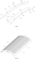
- the electrostatic dust removal apparatus is bent into an arc shape about an axis, the axis extends along the length direction of the frame and is located at the middle of the frame in the width direction of the frame.
- Electrostatic dust removal apparatus 1 Frame 10; End positioning structure 110; First fixing element 120; First fixing groove 121; Second fixing element 130; Second fixing groove 131; Main frame 150; Bottom frame 140; Position-limiting pin 141; Position-limiting sleeve 151; Male snap 142; Female snap 152; Electrode unit 20; high-potential unit 21; low-potential unit 22; Conducting part 210; Electrical field generator 211; Conducting end 212; Insulating part 220; Positioning protrusion 230; Positioning ring 240; Insulating end 221; High-potential conductor 30; Low-potential conductor 40;First positioning element 50; First positioning tooth 510; First tooth space 520; First stud 530; First rib 550; First linear rib 551; First corner rib 552; First positioning groove 231; Second positioning groove 232;Second positioning element 60; Second positioning tooth 610; Second tooth space 620; Second stud 630; axis L.
- orientational or positional relations such as “center”, “upper”, “lower”, “front”, “rear”, “left”, “right”, “vertical”, “horizontal”, “top”, “bottom”, “inside” and “outside”, are all on the basis of the orientational or positional relations illustrated in the drawings.
- Each of those terms is merely for the convenience and simplification of the description of the present disclosure, does not indicate or imply that the indicated device or component must be in a particular orientation or must be constructed and operated in a particular orientation, and therefore cannot be construed as limiting the present disclosure.
- the electrostatic dust removal apparatus 1 includes a frame 10 and a plurality of electrode units 20.
- the plurality of electrode units 20 are provided on the frame 10 and are spaced apart from each other.
- the plurality of electrode units 20 include at least one high-potential unit 21 and at least one low-potential unit 22, and the at least one high-potential unit 21 and the at least one low-potential unit 22 are arranged alternately. That is, one or more of the plurality of electrode units 20 may be formed as the high-potential unit(s) 21, and one or more of the plurality of electrode units 20 may be formed as the low-potential unit(s) 22.
- the electrode unit 20 adjacent to the high-potential unit 21 is used as the low-potential unit 22
- the electrode unit 20 adjacent to the low-potential unit 22 is used as the high-potential unit 21.
- the plurality of electrode units 20 are arranged in an order of a high-potential unit 21, a low-potential unit 22, a high-potential unit 21, a low-potential unit 22 and so on.
- An air channel for removing dust is formed between the high-potential unit 21 and the low-potential unit 22 which are adjacent to each other.
- the air channel for removing dust extends along a length direction of the high-potential unit 21 and the low-potential unit 22 which are adjacent to each other.
- Each of the plurality of electrode units 20 includes a conducting part 210 and an insulating part 220.
- the conducting part 210 is a conductive plastic part.
- the conducting part 210 includes an electrical field generator 211 and a conducting end 212.
- the electrical field generator 211 refers to a portion of the conducting part 210 that is configured to generate an electrical field
- the conducting end 212 refers to a portion of the conducting part 210 that is configured to realize an electrical connection.
- the insulating part 220 covers at least a portion of the electrical field generator 211.
- the conducting end 212 is exposed from the insulating part 220 for the electrical connection.
- the conducting part 210 of the electrode unit 20 is made from conductive plastic.
- the conductive plastic is easier and more flexible to machine, and can form various structures adapted for different application environments and structural demands of the electrostatic dust removal apparatus 1, and further the cost of the conductive plastic is lower.
- conductive ink is used to form an electrode.
- it requires an additional process to apply the conductive ink, and it is difficult to guarantee the comprehensiveness and uniformity of the application.
- the use of the conductive plastic does not require any additional process, and the stability of the electrical field can be guaranteed.
- At least a portion of the electrical field generator 211 of the conducting part 210 is covered by the insulating part 220, such that electrical field generators 211 adjacent to each other can be separated by at least one layer of insulating material. Therefore, on one hand, the corona discharge between adjacent electrode units 20 can be avoided, so as to reduce the generation of ozone and the risk of electric shock, greatly improving the use security.
- the conducting part 210 and the insulating part 220 can be formed as an integral part, simplifying the assembly. Further, each of the electrode units 20 can be formed as an individual component, facilitating replacement of an individual electrode unit 20 during the process of the manufacture and use.
- the electrode unit 20 can be replaced independently without disposing of the plurality of electrode units 20 or the whole electrostatic dust removal apparatus, thereby indirectly improving the product yield and saving the manufacture cost. Further, during the process of use, an individual electrode unit 20 can be replaced, thereby making the repair and maintain during the process of use more convenient.
- a long and narrow air channel for removing dust can be formed between adjacent electrode units 20, and can extend along the length direction of each of the adjacent electrode units 20. In this way, the wind resistance of the electrostatic dust removal apparatus 1 can be reduced so as to improve the dust removal efficiency.
- the conductive plastic has a tensile strength in the range of 20MPa to 28MPa, an ultimate elongation of not less than 10%, a flexural strength in the range of 32MPa to 40MPa, a flexural modulus in the range of 3000MPa to 3800MPa, and a notched impact strength in the range of 100J/m to 140J/m.
- the conductive plastic has a tensile strength of 24MPa, a flexural strength of 36MPa, a flexural modulus of 3400MPa, and a notched impact strength of 120J/m.
- the conductive plastic has a surface resistivity of 10 3 Ohm-cm, a specific weight in the range of 0.92 g/cm 3 to 1.12 g/cm 3 , flammability in HB class, a shrinkage in the range of 0.4% to 0.8%, and a heat deformation temperature in the range of 95°C to 115°C.
- the conductive plastic has a specific weight of 1.02 g/cm 3 and a heat deformation temperature of 105°C.
- the conductive plastic is subject to a drying process in which drying temperature is in the range of 70°C to 90°C and drying time is in the range of 2 hours to 4 hours.
- drying temperature is 80°C.
- the conductive plastic is subject to an injection molding in which melt temperature is in the range of 180°C to 240°C, front barrel temperature is in the range of 180°C to 240°C, middle barrel temperature is in the range of 180°C to 235°C, rear barrel temperature is in the range of 180°C-230°C, mold temperature is in the range of 50°C to 80°C and injection pressure is in the range of 180°C-240°C.
- the conductive plastic has advantages such as good electrical conduction, good shape retention, light weight and high temperature resistance.
- the electrode unit 20 made from the conductive plastic may have advantages such as lower risk of being damaged and high durability.
- the parameters of properties of the conductive plastic are given in the following table.
- Properties Test Standard (Standard) Test Condition (Condition) Unit Value Mechanical Properties Tensile Strength ASTM D638 10mm/min MPa 24 Ultimate elongation ASTM D638 10mm/min % ⁇ 10 Flexural Strength (Tear strength) ASTM D790 2mm/min MPa 36 Flexural Modulus ASTM D790 2mm/min MPa 3400 IZOD Notched Impact Strength ASTM D256 2.75J J/m 120 Electrical Properties Surface Resistivity ASTM D257 / Ohm-cm 10 3 Others Specific weight ASTM D792 23°C g/cm 3 1.02 Flammability UL94 1.5mm Class HB Shrinkage (Mold Shrinkage) ASTM D955 23°C % 0.4-0.8 Heat Deformation Temperature (HDT) ASTM D1525 1.82MPa °C 105 Drying Process (Materials Drying Process) Drying Temperature °C 80 Drying Time Hour 2-4 Injection Process
- the electrical field generators 211 adjacent to each other have surfaces facing each other, one of the surfaces is covered by the insulating part 220 and the other of the surfaces is exposed from the insulating part 220, forming a semi-covered structure.
- one side surface of an electrical field generator 211 in its thickness direction and two opposite curved surfaces of the electrical field generator 211 in its width direction are covered by the insulating part 220.
- one side surface is covered by its corresponding insulating part 220 so as to guarantee that the two adjacent electrical field generators 211 are separated by an insulating layer. In this way, the use security of the electrostatic dust removal apparatus 1 can be guaranteed cost-efficiently.
- the insulating part 220 covers the whole electrical field generator 211, forming a fully covered structure.
- two side surfaces of an electrical field generator 211 in its thickness direction, two opposite curved surfaces of the electrical field generator 211 in its width direction and the end of the electrical field generator 211 further away from the conducting end 212 are all covered by the insulating part 220.
- creepage between the electrical field generators 211 adjacent to each other can further be avoided, and the electric shock can be prevented so as to greatly improve the security.
- the air breakdown can be eliminated, therefore the problem of ozone generation can be solved from the origin and the concentration of the generated ozone is quite low.
- the conducting part 210 and the insulating part 220 of each of the plurality of electrode units 20 are formed integrally by injection molding.
- an additional insulator may be provided between the electrodes adjacent to each other. The manufacture and assembly of the additional insulator are independent from those of any of the electrodes. Therefore, the additional insulator and the electrode cannot formed as an integrated whole, and problems such as uncontrollability of thickness, difficulty in mass production, instability in structure and poor uniformity in spacing between the electrodes may occur.
- the conducting part 210 and the insulating part 220 of the electrode unit 20 are formed integrally by injection molding, so that the conducting part 210 and the insulating part 220 are manufactured integrally to form an integrated whole. In this way, the assembly is simplified, and the structure is more stable. Further, a mold can be used, so as to guarantee a controllable uniformity of the thickness of the electrode units 20 and easiness for mass production. In addition, good uniformity in spacings among the electrodes can be guaranteed, thus the uniformity of the wind resistance in each position of the electrostatic dust removal apparatus 1 can be guaranteed so as to improve the dust removal uniformity.
- the plurality of electrode units 20 are arranged along the thickness direction of the plurality of electrode units 20, and two ends of each of the plurality of electrode units 20 are detachably mounted onto two opposite sides of the frame 10 respectively. In this way, the wind resistance can be lowered, the area for collecting dust can be increased, and the space usage of the electrostatic dust removal apparatus 1 can be reasonably set.
- one of the electrode units 20 adjacent to each other is provided with a positioning ring 240, and the other of the electrode units 20 adjacent to each other is provided with a positioning protrusion 230 configured to be inserted into the positioning ring 240.
- each of the positioning protrusion 230 and the positioning ring 240 is formed by a corresponding insulating part 220.
- a plurality of positioning rings 240 are provided on one side surface of each of the plurality of the electrode unit 20 in the thickness direction of the electrode unit 20, the plurality of positioning rings 240 are divided into two rows along the width direction of the electrode unit 20, and each positioning ring 240 forms a groove by its annular shape.
- a plurality of positioning protrusions 230 are provided on the other side surface of each of the plurality of electrode units 20 in the thickness direction of the electrode unit 20, the plurality of positioning protrusions 230 are divided into two rows along the width direction of the electrode unit 20, and each of the positioning protrusions 230 is configured to be inserted into the groove of its corresponding positioning ring 240.
- the electrode units 20 adjacent to each other can be assembled together by the fitting of the respective positioning protrusions 230 to the respective positioning rings 240. In this way, the plurality of electrode units 20 can be fixed together so as to form an unified whole, and then can be assembled with the frame 10. Further, the provision of the positioning protrusions 230 and the positioning rings 240 can reliably define the spacings between the electrode units 20 adjacent to each other to guarantee the uniformity of the air channels for removing dust.
- an end positioning structure 110 is provided on the frame 10.
- the positioning ring 240 or the positioning protrusion 230 on the outermost electrode unit 20 fits to the end positioning structure 110.
- the structure of the end positioning structure 110 is suitable to fit to either of the positioning ring 240 and the positioning protrusion 230.
- the end positioning structure 110 fits to the positioning ring 240 or the positioning protrusion 230.
- a plurality of end positioning structures 110 are provided on either of two opposite sides of the frame 10 in the length direction of the frame 10, and are arranged spaced apart from each other in the width direction of the frame 10.
- Each end positioning structure 110 has a notch in its surface which faces the inner side of the frame 10, and the positioning ring 240 or the positioning protrusion 230 can fit into the notch so as to fit to the end positioning structure 110.
- the above configuration can enhance the stability of the relative positions of the plurality of electrode units 20 and the frame 10, which can further improve the structural reliability of the electrostatic dust removal apparatus 1.
- the electrostatic dust removal apparatus 1 further includes a high-potential conductor 30 and a low-potential conductor 40.
- the high-potential conductor 30 is connected to the conducting end 212 of each of the plurality of high-potential units 21, so as to cause the plurality of high-potential units 21 to conduct electricity in the same potential.
- the low-potential conductor 40 is connected to the conducting end 212 of each of the plurality of low-potential units 22, so as to cause the plurality of low-potential units 22 to conduct electricity in the same potential.
- the high-potential conductor 30 and the low-potential conductor 40 each can be cylindrical in shape.
- one end of the high-potential unit 21 is the conducting end 212 formed by the conducting part 210 of the high-potential unit 21, and the other end of the high-potential unit 21 is the insulating end 221 formed by the insulating part 220 of the high-potential unit 21.
- One end of the low-potential unit 22 is the conducting end 212 formed by the conducting part 210 of the low-potential unit 22, and the other end of the low-potential unit 22 is the insulating end 221 formed by the insulating part 220 of the low-potential unit 22.
- the conducting ends 212 of the plurality of high-potential units 21 and the insulating ends 221 of the plurality of low-potential units 22 face one side of the frame 10
- the insulating ends 221 of the plurality of high-potential units 21 and the conducting ends 212 of the plurality of low-potential units 22 face an opposite side of the frame 10.
- the high-potential conductor 30 is provided at the one side of the frame 10 and is connected to the conducting end 212 of each of the plurality of high-potential units 21 and the insulating end 221 of each of the plurality of low-potential units 220; and the low-potential conductor 40 is provided at the opposite side of the frame 10 and is connected to the conducting end 212 of each of the plurality of low-potential units 22 and the insulating end 221 of each of plurality of the high-potential units 21.
- the high-potential conductor 30 and the low-potential conductor 40 are provided on two opposite sides of the frame 10 respectively, e.g., the two opposite sides of the frame 10 in the width direction of the frame 10.
- the high-potential conductor 30 and the low-potential conductor 40 can be separated from each other in space to avoid problems such as contact and short circuit between the high-potential conductor 30 and the low-potential conductor 40, so as to guarantee the reliability of the electrical field.
- the provision of the high-potential conductor 30 and the low-potential conductor 40 may further fix the relative positions of the ends of the plurality of electrode units 20.
- the electrostatic dust removal apparatus 1 may further include a first positioning element 50 and a second positioning element 60.
- the high-potential conductor 30 is provided on the first positioning element 40, and the first positioning element 50 fits to the conducting end 212 of each of the plurality of high-potential units 21 and the insulating end 221 of each of the plurality of low-potential units 22.
- the low-potential conductor 40 is provided on the second positioning element 60, and the second positioning element 60 fits to the conducting end 212 of each of the plurality of low-potential units 22 and the insulating end 221 of each of the plurality of high-potential units 21.
- the provision of the first positioning element 50 and the second positioning element 60 may fix the high-potential conductor 30 and the low-potential conductor 40 respectively and connect to the plurality of electrode units 20.
- the first positioning element 50 is provided with a plurality of first positioning teeth 510, and each of a plurality of first tooth spaces 520 is formed between the first positioning teeth 510 adjacent to each other.
- the high-potential conductor 30 extends through the first positioning element 50 along the length direction of the first positioning element 50 and is exposed from the plurality of tooth spaces 520.
- Each of the plurality of first positioning teeth 510 is fitted between the conducting end 212 of one high-potential unit 21 and the insulating end 221 of the low-potential unit 22 adjacent to the high-potential unit 21.
- the second positioning element 60 is provided with a plurality of second positioning teeth 610, and each of a plurality of second tooth spaces 620 is formed between the second positioning teeth 610 adjacent to each other.
- the low-potential conductor 40 extends through the second positioning element 60 along the length direction of the second positioning element 60 and is exposed from the plurality of second tooth spaces 620.
- Each of the plurality of second positioning teeth 610 is fitted between the conducting end 212 of one low-potential unit 22 and the insulating end 221 of the high-potential unit 21 adjacent to the low-potential unit 22.
- the plurality of first positioning teeth 510 may have the same width or different widths
- the plurality of second positioning teeth 610 may have the same width or different widths.
- the width of each of the plurality of first positioning teeth 510 and the width of each of the plurality of second positioning teeth 610 may be set based on the spacing between the conducting end 212 of the corresponding high-potential unit 21 and the insulating end 221 of the corresponding low-potential unit 22.
- the width of the tooth top of each of the first positioning tooth 510 and the second positioning tooth 610 can be gradually decreased for convenience of assembly.
- the first positioning element 50 and the second positioning element 60 provided with the high-potential conductor 30 and the low-potential conductor 40 respectively thereon can be assembled with the plurality of electrode units 20, improving the structural stability of the plurality of electrode units 20 and the reliability of the electrical connection.
- the first positioning element 50 is provided with a plurality of first studs 530 spaced apart from each other along its length direction, and the plurality of first studs 530 are mounted onto the frame 10 by a plurality of first screw fasteners (such as screw bolts or screw nails) respectively.
- first screw fasteners such as screw bolts or screw nails
- the second positioning element 60 is provided with a plurality of second studs 630 spaced apart from each other along its length direction, and the plurality of second studs 630 are mounted onto the frame 10 by a plurality of second screw fasteners (such as screw bolts or screw nails) respectively.
- second screw fasteners such as screw bolts or screw nails
- the frame 10 is provided with a plurality of first ribs 550 which are spaced apart from each other and surround the first positioning element 50, and is provided with a plurality of second ribs (not shown in the drawings) which are spaced apart from each other and surround the second positioning element 60.
- the plurality of first ribs 550 may include a first linear rib 551 and two first corner ribs 552, the first linear rib 551 extends along the length direction of the first positioning element 50 and can press against the inner side of the first positioning element 50, and the two first linear ribs 551 can press against two corners at the outer side of the first positioning element 50 respectively.
- the plurality of second ribs include a second linear rib and two second corner ribs, the second linear rib extends along the length direction of the second positioning element 60 and can press against the inner side of the second positioning element 60, and the two corner ribs can press against two corners at the outer side of the second positioning element 60 respectively.
- the first positioning element 50 and the second positioning element 60 can be stably fixed onto the frame 10, realizing a convenient connection and a simplified and reasonable structure.
- each of the first corner rib 552 and the second corner rib may have a different specific structure in a different embodiment.
- the first corner rib 552 and the second corner rib each may be a U-shaped structure; however, in the embodiment shown in FIG. 15 , the first corner rib 552 and the second corner rib each may be an L-shaped structure.
- the one side of the frame 10 described above is provided with a first fixing element 120, and the opposite side of the frame 10 described above is provided with a second fixing element 130.
- the first fixing element 120 is provided with a plurality of first fixing grooves 121 spaced apart from each other along its length direction, and the conducting ends 212 of the plurality of high-potential units 21 and the insulating ends 221 of the plurality of low-potential units 22 are fitted into the plurality of first fixing grooves 121 respectively.
- the second fixing element 130 is provided with a plurality of second fixing grooves 131 spaced apart from each other along its length direction, and the conducting ends 212 of the plurality of low-potential units 22 and the insulating ends 221 of the plurality of high-potential units 21 are fitted into the plurality of second fixing grooves 131 respectively.
- the plurality of electrode units 20 can be fixed onto the frame 10, and the stability of the plurality of electrode units 20 and the uniformity of the spacings among the plurality of electrode units 20 can be guaranteed.
- the first fixing groove 121 has a width gradually increasing from its bottom to its opening
- the second fixing groove 131 has a width gradually increasing from its bottom to its opening.
- the frame 10 is configured as a rectangle-shape which surrounds the plurality of electrode units 20.
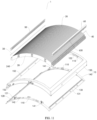
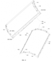
- the electrostatic dust removal apparatus 1 can be bent into an arc shape about an axis L.
- the axis L extends along the length direction of the frame 10 and is located at the middle of the frame 10 in the width direction of the frame 10.
- each of the plurality of electrode units 20 extends along the width direction of the frame 10, the plurality of electrode units 20 are provided spaced apart from each other along the length direction of the frame 10, and the two ends of each of the plurality of electrode units 20 are detachably mounted onto two opposite sides of the frame 10 in the width direction respectively.
- the overall shape of the electrostatic dust removal apparatus 1 is not limited to any particular shape, and the electrostatic dust removal apparatus 1 can be configured as any suitable shape according to a practical application environment.
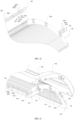
- the frame 10 includes a main frame 150 and a bottom frame 140.
- the bottom frame 140 is detachably mounted onto the main frame 150, and an installation space is defined between the bottom frame 140 and the main frame 150.
- Both ends of each of the plurality of electrode units 20, the first positioning element 50, the second positioning element 60, the high-potential conductor 30, the low-potential conductor 40, the first fixing element 120 and the second fixing element 130 may be provided in the installation space.
- the frame 10 can provide shelter and protection for these structures, allow the appearance of the electrostatic dust removal apparatus 1 more pleasant, and facilitate assembly and disassembly of the overall structure.
- an end positioning structure 110 is formed on both of the main frame 150 and the bottom frame 140, that is, a complete end positioning structure 110 can be formed when the main frame 150 and the bottom frame 140 are in a snap-fit connection.
- the main frame 150 is configured with the first rib 550 and the second rib
- the bottom frame 140 is configured with the first fixing element 120 and the second fixing element 130
- the first positioning element 50 and the second positioning element 60 are mounted on the main frame 150.
- one of the main frame 150 and the bottom frame 140 is provided with a male snap 142 and the other of the main frame 150 and the bottom frame 140 is provided with a female snap 152, and the male snap 142 can be snapped onto the female snap 152.
- a plurality of female snaps 152 may be provided on the main frame 150 and are arranged spaced apart from each other along the circumferential direction of the main frame 150
- a plurality of male snaps 142 may be provided on the bottom frame 140 and are arranged spaced apart from each other along the circumferential direction of the bottom frame 140
- the plurality of male snaps 142 can be snapped into the plurality of female snaps 152 in one-to-one correspondence.
- one of the main frame 150 and the bottom frame 140 is provided with a position-limiting pin 141 and the other of the main frame 150 and the bottom frame 140 is provided with a position-limiting sleeve 151, and the position-limiting pin 141 is configured to be inserted into the position-limiting sleeve 151.
- a plurality of position-limiting pins 141 are arranged on each of two opposite sides of the bottom frame 140 in the length direction of the bottom frame 140 and are spaced apart from each other
- a plurality of position-limiting sleeves 151 are arranged on each of two opposite sides of the main frame 150 in the length direction of the main frame 150 and are spaced apart from each other
- the plurality of position-limiting pins 141 can be inserted into the plurality of position-limiting sleeves 151 in one-to-one correspondence.
- the provision of the position-limiting pin 141 and the position-limiting sleeve 151 may facilitate quick determination of the relative mounting positions of the main frame 150 and the bottom frame 140, that is, may enable pre-positioning, therefore saving time and energy for mounting.
- the male snap 142 and the female snap 152 can make the installation of the main frame 150 and the bottom frame 140 more firm and stable and make the assembly and disassembly of the main frame 150 and the bottom frame 140 more convenient.
- the electrode unit 20 of an electrostatic dust removal apparatus includes a conducting part 210 and an insulating part 220.
- the conducting part 210 is a conductive plastic part and includes an electrical field generator 211 and a conducting end 212.
- the insulating part 220 covers at least a portion of the electrical field generator 211.
- the electrode unit 20 of the electrostatic dust removal apparatus has advantages such as lower manufacture cost, easiness to form various structures, high security and convenience for assembly.
Landscapes
- Electrostatic Separation (AREA)
Description
- The present application claims the priority of the
Chinese Patent Application No. 201910762346.8 filed by Freudenberg Apollo Filtration Technologies Co. Ltd. on August 19, 2019 - The present disclosure relates to the field of air purification, and more particularly, to an electrostatic dust removal apparatus and an electrode unit thereof.
- Electrostatic dust removal is one of methods for removing dust from one or more gases. The principle of the electrostatic dust removal method can be summarized as follows. When a gas and dust particles entrained in the gas pass through a high-voltage electrostatic field, the gas is electrically separated from the dust particles. The dust particles bond with negative ions and are charged negatively. Then the dust particles approach a surface of an anode and are deposited on the surface after discharging. That is, in a strong electric field, an air molecule is ionized into a positive ion and an electron, the electron may encounter the dust particle during approaching the anode, and thus the dust particle is charged negatively so as to be adsorbed onto the anode and then is collected on the anode.
- In the related art, an electrostatic dust removal apparatus usually uses an electrode made of metal. Metal is not only costly, but also difficult to be machined and thus difficult to be processed into various shapes. In addition, corona discharge is liable to occur between a high-potential electrode and a low-potential electrode which are adjacent to each other, causing production of ozone and occurrence of an electric shock, which affect the use security. In order to solve the problem, in some electrostatic dust removal apparatuses, an additional insulator is provided between the adjacent electrodes, increasing the assembling complexity.
CN108855621A discloses an electrostatic dust collector. The electrostatic dust collector includes a plurality of electrostatic dust collecting sheets arranged and fixed in parallel with each other in order to form a multi-layer structure. Conductive layers of the plurality of electrostatic dust collecting sheets are connected to a high-voltage electrode or a ground electrode in an alternate manner to form a structure that the conductive layer of one electrostatic dust collecting sheet is connected to the high-voltage electrode, and the conductive layer of another electrostatic dust collecting sheet is connected to the ground electrode. - The present disclosure aims to solve at least one of the technical problems in the prior art. To this end, one aim of the present disclosure is to provide an electrostatic dust removal apparatus as defined in
claim 1, which has advantages such as lower manufacture cost, easiness to form various structures, high security and convenience for assembly. - The present disclosure also provides an electrode unit of an electrostatic dust removal apparatus.
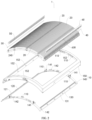
- In order to realize the above aims, according to embodiments in a first aspect of the present disclosure, an electrostatic dust removal apparatus is provided, including: a frame; and a plurality of electrode units including a plurality of high-potential units and a plurality of low-potential units. The plurality of electrode units are provided on the frame and are spaced apart from each other. The plurality of high-potential units and the plurality of low-potential units are arranged alternately, and an air channel for removing dust is formed between the electrode units adjacent to each other. Each of the plurality of electrode units includes a conducting part and an insulating part, the conducting part is a conductive plastic part and includes an electrical field generator and a conducting end, and the insulating part covers at least a portion of the electrical field generator. The plurality of electrode units are arranged along a thickness direction of the plurality of electrode units, and two ends of each of the plurality of electrode units are detachably mounted onto two opposite sides of the frame respectively. The electrostatic dust removal apparatus further includes: one high-potential conductor provided at one side of the frame, the high-potential conductor being connected to the conducting end of each of the plurality of high-potential units; and one low-potential conductor provided at another side of the frame that is opposite to the one side, the low-potential conductor being connected to the conducting end of each of the plurality of low-potential units.
- The electrostatic dust removal apparatus according to embodiments of the present disclosure has advantages such as lower manufacture cost, easiness to form various structures, high security and convenience for assembly.
- The electrostatic dust removal apparatus according to embodiments of the present disclosure may further include one or more of the following additional technical features.
- According to some specific embodiments of the present disclosure, the insulating part covers the whole electrical field generator; or the electrical field generators adjacent to each other have surfaces facing each other, one of the surfaces is covered by the insulating part, and the other of the surfaces is exposed from the insulating part.
- According to some specific embodiments of the present disclosure, the conducting part and the insulating part of each of the plurality of electrode units are formed integrally by injection molding.
- According to some specific embodiments of the present disclosure, one of the electrode units adjacent to each other is provided with a positioning ring, and the other of the electrode units adjacent to each other is provided with a positioning protrusion configured to be inserted into the positioning ring.
- Further, an end positioning structure is provided on the frame, and the positioning ring or the positioning protrusion of the outermost electrode unit fits to the end positioning structure.
- Further, one end of the high-potential unit is the conducting end formed by the conducting part of the high-potential unit, and the other end of the high-potential unit is the insulating end formed by the insulating part of the high-potential unit. One end of the low-potential unit is the conducting end formed by the conducting part of the low-potential unit, and the other end of the low-potential unit is an insulating end formed by the insulating part of the low-potential unit. The conducting ends of the plurality of high-potential units and the insulating ends of the plurality of low-potential units face the one side of the frame, and the insulating ends of the plurality of high-potential units and the conducting ends of the plurality of low-potential units face the other side of the frame that is opposite to the one side.
- Further, the high-potential conductor is connected to the insulating end of each of the plurality of low-potential units; and the low-potential conductor is connected to the insulating end of each of the plurality of high-potential units.
- According to some specific embodiments of the present disclosure, the electrostatic dust removal apparatus further includes: a first positioning element, the high-potential conductor being provided on the first positioning element, and the first positioning element fitting to the conducting end of each of the plurality of high-potential units and the insulating end of each of the plurality of low-potential units; and a second positioning element, the low-potential conductor being provided on the second positioning element, and the second positioning element fitting to the conducting end of each of the plurality of low-potential units and the insulating end of each of the plurality of high-potential units.
- Further, the first positioning element is provided with a plurality of first positioning teeth, each of a plurality of first tooth spaces is formed between the first positioning teeth adjacent to each other, the high-potential conductor extends through the first positioning element and is exposed from the plurality of first tooth spaces, and each of the plurality of first positioning teeth is fitted between the conducting end of one high-potential unit and the insulating end of the low-potential unit adjacent to the one high-potential unit. The second positioning element is provided with a plurality of second positioning teeth, each of a plurality of second tooth spaces is formed between the second positioning teeth adjacent to each other, the low-potential conductor extends through the second positioning element and is exposed from the plurality of second tooth spaces, and each of the plurality of second positioning teeth is fitted between the conducting end of one low-potential unit and the insulating end of the high-potential unit adjacent to the one low-potential unit.
- According to some specific embodiments of the present disclosure, the conducting end of each of the plurality of high-potential units and the insulating end of each of the plurality of low-potential units are provided with a first positioning groove respectively, and the first positioning element is fitted into a plurality of first positioning grooves. Further, the conducting end of each of the plurality of low-potential units and the insulating end of each of the plurality of high-potential units are provided with a second positioning groove respectively, and the second positioning element is fitted into a plurality of second positioning grooves.
- According to some embodiments of the present disclosure, the first positioning element is provided with a plurality of first studs spaced apart from each other along its length direction, and the plurality of first studs are mounted on the frame by a plurality of first screw fasteners respectively. Further, the second positioning element is provided with a plurality of second studs spaced apart from each other along its length direction, and the plurality of second studs are mounted on the frame by a plurality of second screw fasteners respectively.
- According to some specific embodiments of the present disclosure, the frame is provided with a plurality of first ribs which are spaced apart from each other and surround the first positioning element, and is provided with a plurality of second ribs which are spaced apart from each other and surround the second positioning element.
- According to some specific embodiments of the present disclosure, the frame is configured as a rectangle shape which surrounds the plurality of electrode units.
- Further, each of the plurality of electrode units extends along the width direction of the frame, the plurality of electrode units are provided spaced apart from each other along the length direction of the frame, and two ends of each of the plurality of electrode units are detachably mounted onto two opposite sides of the frame in the width direction respectively.
- Further, the electrostatic dust removal apparatus is bent into an arc shape about an axis, the axis extends along the length direction of the frame and is located at the middle of the frame in the width direction of the frame.
- Additional aspects and advantages of the present disclosure will be given at least in part in the following description, or become apparent partially from the following description, or can be learned from practicing of the present disclosure.
- The above and/or additional aspects and advantages of the present disclosure will become clear and easy to understand from the description of embodiments below in conjunction with the accompanying drawings, in which:
-
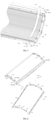
FIG. 1 is a schematic diagram showing a structure of an electrostatic dust removal apparatus according to an embodiment of the present disclosure. -
FIG. 2 is an exploded diagram showing an electrostatic dust removal apparatus according to an embodiment of the present disclosure. -
FIG. 3 is a schematic diagram showing connections among a plurality of electrode units and first and second positioning elements in an electrostatic dust removal apparatus according to an embodiment of the present disclosure. -
FIG. 4 is a schematic diagram showing the connection between a plurality of electrode units and a bottom frame in an electrostatic dust removal apparatus according to an embodiment of the present disclosure. -
FIG. 5 is a schematic diagram showing the connection between a plurality of electrode units and a main frame in an electrostatic dust removal apparatus according to an embodiment of the present disclosure. -
FIG. 6 is an exploded view of a frame of an electrostatic dust removal apparatus according to an embodiment of the present disclosure. -
FIG. 7 is a schematic diagram showing a structure of one side of an electrode unit of an electrostatic dust removal apparatus according to an embodiment of the present disclosure. -
FIG. 8 is a schematic diagram showing a structure of a opposite side of an electrode unit of an electrostatic dust removal apparatus according to an embodiment of the present disclosure; -
FIG. 9 is an exploded view of an electrode unit of an electrostatic dust removal apparatus according to an embodiment of the present disclosure. -
FIG. 10 is a schematic diagram showing a structure of an electrostatic dust removal apparatus according to another embodiment of the present disclosure. -
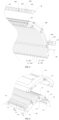
FIG. 11 is an exploded view of an electrostatic dust removal apparatus according to yet another embodiment of the present disclosure. -
FIG. 12 is a schematic diagram showing connections among a plurality of electrode units and first and second positioning elements of an electrostatic dust removal apparatus according to yet another embodiment of the present disclosure. -
FIG. 13 is a schematic diagram showing the connection between a plurality of electrode units and the bottom frame in an electrostatic dust removal apparatus according to yet another embodiment of the present disclosure. -
FIG. 14 is a schematic diagram showing the connection between a plurality of electrode units and the main frame in an electrostatic dust removal apparatus according to yet another embodiment of the present disclosure. -
FIG. 15 is an exploded view of a frame of an electrostatic dust removal apparatus according to yet another embodiment of the present disclosure. -
FIG. 16 is a schematic diagram showing a structure of one side of an electrode unit in an electrostatic dust removal apparatus according to another embodiment of the present disclosure. -
FIG. 17 is a schematic diagram showing a structure of an opposite side of the electrode unit of an electrostatic dust removal apparatus according to another embodiment of the present disclosure. -
FIG. 18 is an exploded view of an electrode unit of an electrostatic dust removal apparatus according to another embodiment of the present disclosure. - Electrostatic
dust removal apparatus 1;Frame 10;End positioning structure 110;First fixing element 120; First fixinggroove 121;Second fixing element 130;Second fixing groove 131;Main frame 150;Bottom frame 140; Position-limitingpin 141; Position-limitingsleeve 151;Male snap 142;Female snap 152;Electrode unit 20; high-potential unit 21; low-potential unit 22; Conductingpart 210;Electrical field generator 211; Conductingend 212; Insulatingpart 220;Positioning protrusion 230;Positioning ring 240; Insulatingend 221; High-potential conductor 30; Low-potential conductor 40;First positioning element 50;First positioning tooth 510;First tooth space 520;First stud 530;First rib 550; Firstlinear rib 551;First corner rib 552;First positioning groove 231;Second positioning groove 232;Second positioning element 60;Second positioning tooth 610;Second tooth space 620;Second stud 630; axis L. - Embodiments of the present disclosure will be described in detail below with reference to examples thereof as illustrated in the accompanying drawings, throughout which same or similar elements, or elements having same or similar functions are denoted by same or similar reference numerals. The embodiments described below with reference to the drawings are illustrative only, and are only intended to explain, rather than limiting, the present disclosure.
- In the description of the present disclosure, it shall be appreciated that, terms illustrating orientational or positional relations, such as "center", "upper", "lower", "front", "rear", "left", "right", "vertical", "horizontal", "top", "bottom", "inside" and "outside", are all on the basis of the orientational or positional relations illustrated in the drawings. Each of those terms is merely for the convenience and simplification of the description of the present disclosure, does not indicate or imply that the indicated device or component must be in a particular orientation or must be constructed and operated in a particular orientation, and therefore cannot be construed as limiting the present disclosure.
- It shall be noted that, terms such as "first" and "second" are only illustrative, and cannot be construed as indicating or implying the degree of relative importance or the number of the technical features indicated. Therefore, features defined with "first" or "second" may implicitly or explicitly include one or more such features. Further, in the description of the present disclosure, "a plurality of" means two or more, unless otherwise specifically indicated.
- An electrostatic
dust removal apparatus 1 according to embodiments of the present disclosure will be described below with reference to the drawings. - As illustrated in
FIG. 1 to FIG. 18 , the electrostaticdust removal apparatus 1 according to the embodiments of the present disclosure includes aframe 10 and a plurality ofelectrode units 20. - The plurality of
electrode units 20 are provided on theframe 10 and are spaced apart from each other. The plurality ofelectrode units 20 include at least one high-potential unit 21 and at least one low-potential unit 22, and the at least one high-potential unit 21 and the at least one low-potential unit 22 are arranged alternately. That is, one or more of the plurality ofelectrode units 20 may be formed as the high-potential unit(s) 21, and one or more of the plurality ofelectrode units 20 may be formed as the low-potential unit(s) 22. In other words, theelectrode unit 20 adjacent to the high-potential unit 21 is used as the low-potential unit 22, and theelectrode unit 20 adjacent to the low-potential unit 22 is used as the high-potential unit 21. For example, the plurality ofelectrode units 20 are arranged in an order of a high-potential unit 21, a low-potential unit 22, a high-potential unit 21, a low-potential unit 22 and so on. An air channel for removing dust is formed between the high-potential unit 21 and the low-potential unit 22 which are adjacent to each other. The air channel for removing dust extends along a length direction of the high-potential unit 21 and the low-potential unit 22 which are adjacent to each other. - Each of the plurality of
electrode units 20 includes a conductingpart 210 and aninsulating part 220. The conductingpart 210 is a conductive plastic part. The conductingpart 210 includes anelectrical field generator 211 and a conductingend 212. It shall be noted that, theelectrical field generator 211 refers to a portion of the conductingpart 210 that is configured to generate an electrical field, and the conductingend 212 refers to a portion of the conductingpart 210 that is configured to realize an electrical connection. The insulatingpart 220 covers at least a portion of theelectrical field generator 211. The conductingend 212 is exposed from the insulatingpart 220 for the electrical connection. - In the electrostatic
dust removal apparatus 1 according to embodiments of the present disclosure, the conductingpart 210 of theelectrode unit 20 is made from conductive plastic. Compared with metal in the related art, the conductive plastic is easier and more flexible to machine, and can form various structures adapted for different application environments and structural demands of the electrostaticdust removal apparatus 1, and further the cost of the conductive plastic is lower. In the related art, conductive ink is used to form an electrode. However, it requires an additional process to apply the conductive ink, and it is difficult to guarantee the comprehensiveness and uniformity of the application. In the embodiments of the present disclosure, the use of the conductive plastic does not require any additional process, and the stability of the electrical field can be guaranteed. - At least a portion of the
electrical field generator 211 of the conductingpart 210 is covered by the insulatingpart 220, such thatelectrical field generators 211 adjacent to each other can be separated by at least one layer of insulating material. Therefore, on one hand, the corona discharge betweenadjacent electrode units 20 can be avoided, so as to reduce the generation of ozone and the risk of electric shock, greatly improving the use security. On the other hand, through the above covering, the conductingpart 210 and the insulatingpart 220 can be formed as an integral part, simplifying the assembly. Further, each of theelectrode units 20 can be formed as an individual component, facilitating replacement of anindividual electrode unit 20 during the process of the manufacture and use. For example, during the process of manufacture, if it finds one or more defects in anindividual electrode unit 20, theelectrode unit 20 can be replaced independently without disposing of the plurality ofelectrode units 20 or the whole electrostatic dust removal apparatus, thereby indirectly improving the product yield and saving the manufacture cost. Further, during the process of use, anindividual electrode unit 20 can be replaced, thereby making the repair and maintain during the process of use more convenient. - In addition, a long and narrow air channel for removing dust can be formed between
adjacent electrode units 20, and can extend along the length direction of each of theadjacent electrode units 20. In this way, the wind resistance of the electrostaticdust removal apparatus 1 can be reduced so as to improve the dust removal efficiency. - In some specific embodiments of the present disclosure, the conductive plastic has a tensile strength in the range of 20MPa to 28MPa, an ultimate elongation of not less than 10%, a flexural strength in the range of 32MPa to 40MPa, a flexural modulus in the range of 3000MPa to 3800MPa, and a notched impact strength in the range of 100J/m to 140J/m. Preferably, the conductive plastic has a tensile strength of 24MPa, a flexural strength of 36MPa, a flexural modulus of 3400MPa, and a notched impact strength of 120J/m.
- Further, the conductive plastic has a surface resistivity of 103 Ohm-cm, a specific weight in the range of 0.92 g/cm3 to 1.12 g/cm3, flammability in HB class, a shrinkage in the range of 0.4% to 0.8%, and a heat deformation temperature in the range of 95°C to 115°C. Preferably, the conductive plastic has a specific weight of 1.02 g/cm3 and a heat deformation temperature of 105°C.
- Further, the conductive plastic is subject to a drying process in which drying temperature is in the range of 70°C to 90°C and drying time is in the range of 2 hours to 4 hours. Preferably, the conductive plastic is subject to a drying process in which the drying temperature is 80°C.
- Further, the conductive plastic is subject to an injection molding in which melt temperature is in the range of 180°C to 240°C, front barrel temperature is in the range of 180°C to 240°C, middle barrel temperature is in the range of 180°C to 235°C, rear barrel temperature is in the range of 180°C-230°C, mold temperature is in the range of 50°C to 80°C and injection pressure is in the range of 180°C-240°C.
- It can be obtained that, the conductive plastic has advantages such as good electrical conduction, good shape retention, light weight and high temperature resistance. Thus, in addition to the advantage of low manufacture cost, the
electrode unit 20 made from the conductive plastic may have advantages such as lower risk of being damaged and high durability. - For example, the parameters of properties of the conductive plastic are given in the following table.
Properties Test Standard (Standard) Test Condition (Condition) Unit Value Mechanical Properties Tensile Strength ASTM D638 10mm/min MPa 24 Ultimate elongation ASTM D638 10mm/min % ≥10 Flexural Strength (Tear strength) ASTM D790 2mm/min MPa 36 Flexural Modulus ASTM D790 2mm/min MPa 3400 IZOD Notched Impact Strength ASTM D256 2.75J J/ m 120 Electrical Properties Surface Resistivity ASTM D257 / Ohm- cm 103 Others Specific weight ASTM D792 23°C g/cm3 1.02 Flammability UL94 1.5mm Class HB Shrinkage (Mold Shrinkage) ASTM D955 23°C % 0.4-0.8 Heat Deformation Temperature (HDT) ASTM D1525 1.82MPa °C 105 Drying Process (Materials Drying Process) Drying Temperature °C 80 Drying Time Hour 2-4 Injection Process Melt Temperature °C 180-240 Front Barrel Temperature (Cylinder Temperature) °C 180-240 Middle Barrel Temperature (Cylinder Temperature) °C 180-235 Rear Barrel Temperature (Cylinder Temperature) °C 180-230 Mold Temperature °C 50-80 Injection Pressure Medium Injection Speed Medium - In some specific embodiments of the present disclosure, as illustrated in
FIG. 1 to FIG. 9 , theelectrical field generators 211 adjacent to each other have surfaces facing each other, one of the surfaces is covered by the insulatingpart 220 and the other of the surfaces is exposed from the insulatingpart 220, forming a semi-covered structure. In detail, one side surface of anelectrical field generator 211 in its thickness direction and two opposite curved surfaces of theelectrical field generator 211 in its width direction are covered by the insulatingpart 220. In two opposite side surfaces of twoelectrical field generators 211 adjacent to each other, one side surface is covered by its corresponding insulatingpart 220 so as to guarantee that the two adjacentelectrical field generators 211 are separated by an insulating layer. In this way, the use security of the electrostaticdust removal apparatus 1 can be guaranteed cost-efficiently. - In other specific embodiments of the present disclosure, as illustrated in
FIG. 10 to FIG. 18 , the insulatingpart 220 covers the wholeelectrical field generator 211, forming a fully covered structure. In detail, two side surfaces of anelectrical field generator 211 in its thickness direction, two opposite curved surfaces of theelectrical field generator 211 in its width direction and the end of theelectrical field generator 211 further away from the conductingend 212 are all covered by the insulatingpart 220. In this way, creepage between theelectrical field generators 211 adjacent to each other can further be avoided, and the electric shock can be prevented so as to greatly improve the security. Further, the air breakdown can be eliminated, therefore the problem of ozone generation can be solved from the origin and the concentration of the generated ozone is quite low. - In some specific embodiments of the present disclosure, the conducting
part 210 and the insulatingpart 220 of each of the plurality ofelectrode units 20 are formed integrally by injection molding. In the electrostaticdust removal apparatus 1 in the related art, for the purpose of improving the security, an additional insulator may be provided between the electrodes adjacent to each other. The manufacture and assembly of the additional insulator are independent from those of any of the electrodes. Therefore, the additional insulator and the electrode cannot formed as an integrated whole, and problems such as uncontrollability of thickness, difficulty in mass production, instability in structure and poor uniformity in spacing between the electrodes may occur. - In the electrostatic
dust removal apparatus 1 according to embodiments of the present disclosure, the conductingpart 210 and the insulatingpart 220 of theelectrode unit 20 are formed integrally by injection molding, so that the conductingpart 210 and the insulatingpart 220 are manufactured integrally to form an integrated whole. In this way, the assembly is simplified, and the structure is more stable. Further, a mold can be used, so as to guarantee a controllable uniformity of the thickness of theelectrode units 20 and easiness for mass production. In addition, good uniformity in spacings among the electrodes can be guaranteed, thus the uniformity of the wind resistance in each position of the electrostaticdust removal apparatus 1 can be guaranteed so as to improve the dust removal uniformity. - In some specific embodiments of the present disclosure, as illustrated in
FIG. 4 to FIG. 5 andFIG. 13 to FIG. 14 , the plurality ofelectrode units 20 are arranged along the thickness direction of the plurality ofelectrode units 20, and two ends of each of the plurality ofelectrode units 20 are detachably mounted onto two opposite sides of theframe 10 respectively. In this way, the wind resistance can be lowered, the area for collecting dust can be increased, and the space usage of the electrostaticdust removal apparatus 1 can be reasonably set. - Further, as illustrated in
FIG. 7 to FIG. 9 andFIG. 16 to FIG. 18 , one of theelectrode units 20 adjacent to each other is provided with apositioning ring 240, and the other of theelectrode units 20 adjacent to each other is provided with apositioning protrusion 230 configured to be inserted into thepositioning ring 240. - For example, each of the
positioning protrusion 230 and thepositioning ring 240 is formed by a corresponding insulatingpart 220. A plurality of positioning rings 240 are provided on one side surface of each of the plurality of theelectrode unit 20 in the thickness direction of theelectrode unit 20, the plurality of positioning rings 240 are divided into two rows along the width direction of theelectrode unit 20, and eachpositioning ring 240 forms a groove by its annular shape. A plurality of positioningprotrusions 230 are provided on the other side surface of each of the plurality ofelectrode units 20 in the thickness direction of theelectrode unit 20, the plurality of positioningprotrusions 230 are divided into two rows along the width direction of theelectrode unit 20, and each of the positioningprotrusions 230 is configured to be inserted into the groove of itscorresponding positioning ring 240. Theelectrode units 20 adjacent to each other can be assembled together by the fitting of therespective positioning protrusions 230 to the respective positioning rings 240. In this way, the plurality ofelectrode units 20 can be fixed together so as to form an unified whole, and then can be assembled with theframe 10. Further, the provision of the positioningprotrusions 230 and the positioning rings 240 can reliably define the spacings between theelectrode units 20 adjacent to each other to guarantee the uniformity of the air channels for removing dust. - Further, as illustrated in
FIG. 6 andFIG. 15 , anend positioning structure 110 is provided on theframe 10. In the plurality ofelectrode units 20, thepositioning ring 240 or thepositioning protrusion 230 on theoutermost electrode unit 20 fits to theend positioning structure 110. Here, the structure of theend positioning structure 110 is suitable to fit to either of thepositioning ring 240 and thepositioning protrusion 230. In practical applications, depending on thepositioning ring 240 or thepositioning protrusion 230 being provided on theelectrode unit 20 adjacent to theend positioning structure 110, theend positioning structure 110 fits to thepositioning ring 240 or thepositioning protrusion 230. - For example, a plurality of
end positioning structures 110 are provided on either of two opposite sides of theframe 10 in the length direction of theframe 10, and are arranged spaced apart from each other in the width direction of theframe 10. Eachend positioning structure 110 has a notch in its surface which faces the inner side of theframe 10, and thepositioning ring 240 or thepositioning protrusion 230 can fit into the notch so as to fit to theend positioning structure 110. The above configuration can enhance the stability of the relative positions of the plurality ofelectrode units 20 and theframe 10, which can further improve the structural reliability of the electrostaticdust removal apparatus 1. - In some specific embodiments of the present disclosure, as illustrated in
FIG. 2 to FIG. 3 andFIG. 11 to FIG. 12 , there are a plurality of high-potential units 21 and a plurality of low-potential units 22. The electrostaticdust removal apparatus 1 further includes a high-potential conductor 30 and a low-potential conductor 40. The high-potential conductor 30 is connected to the conductingend 212 of each of the plurality of high-potential units 21, so as to cause the plurality of high-potential units 21 to conduct electricity in the same potential. The low-potential conductor 40 is connected to the conductingend 212 of each of the plurality of low-potential units 22, so as to cause the plurality of low-potential units 22 to conduct electricity in the same potential. The high-potential conductor 30 and the low-potential conductor 40 each can be cylindrical in shape. - Further, as illustrated in
FIG. 7 to FIG. 9 and inFIG. 16 to FIG. 18 , one end of the high-potential unit 21 is the conductingend 212 formed by the conductingpart 210 of the high-potential unit 21, and the other end of the high-potential unit 21 is theinsulating end 221 formed by the insulatingpart 220 of the high-potential unit 21. One end of the low-potential unit 22 is the conductingend 212 formed by the conductingpart 210 of the low-potential unit 22, and the other end of the low-potential unit 22 is theinsulating end 221 formed by the insulatingpart 220 of the low-potential unit 22. - Here, the conducting ends 212 of the plurality of high-
potential units 21 and the insulating ends 221 of the plurality of low-potential units 22 face one side of theframe 10, and the insulating ends 221 of the plurality of high-potential units 21 and the conducting ends 212 of the plurality of low-potential units 22 face an opposite side of theframe 10. - Further, as illustrated in
FIG. 1 to FIG. 4 andFIG. 10 to FIG. 13 , the high-potential conductor 30 is provided at the one side of theframe 10 and is connected to the conductingend 212 of each of the plurality of high-potential units 21 and theinsulating end 221 of each of the plurality of low-potential units 220; and the low-potential conductor 40 is provided at the opposite side of theframe 10 and is connected to the conductingend 212 of each of the plurality of low-potential units 22 and theinsulating end 221 of each of plurality of the high-potential units 21. - Therefore, the high-
potential conductor 30 and the low-potential conductor 40 are provided on two opposite sides of theframe 10 respectively, e.g., the two opposite sides of theframe 10 in the width direction of theframe 10. In this way, the high-potential conductor 30 and the low-potential conductor 40 can be separated from each other in space to avoid problems such as contact and short circuit between the high-potential conductor 30 and the low-potential conductor 40, so as to guarantee the reliability of the electrical field. Further, the provision of the high-potential conductor 30 and the low-potential conductor 40 may further fix the relative positions of the ends of the plurality ofelectrode units 20. - In some specific embodiments of the present disclosure, as illustrated in
FIG. 1 to FIG.4 andFIG. 10 to FIG. 13 , the electrostaticdust removal apparatus 1 may further include afirst positioning element 50 and asecond positioning element 60. The high-potential conductor 30 is provided on thefirst positioning element 40, and thefirst positioning element 50 fits to the conductingend 212 of each of the plurality of high-potential units 21 and theinsulating end 221 of each of the plurality of low-potential units 22. The low-potential conductor 40 is provided on thesecond positioning element 60, and thesecond positioning element 60 fits to the conductingend 212 of each of the plurality of low-potential units 22 and theinsulating end 221 of each of the plurality of high-potential units 21. Thus, the provision of thefirst positioning element 50 and thesecond positioning element 60 may fix the high-potential conductor 30 and the low-potential conductor 40 respectively and connect to the plurality ofelectrode units 20. - In particular, as illustrated in
FIG. 2 to FIG. 4 andFIG. 11 to FIG. 13 , thefirst positioning element 50 is provided with a plurality offirst positioning teeth 510, and each of a plurality offirst tooth spaces 520 is formed between thefirst positioning teeth 510 adjacent to each other. The high-potential conductor 30 extends through thefirst positioning element 50 along the length direction of thefirst positioning element 50 and is exposed from the plurality oftooth spaces 520. Each of the plurality offirst positioning teeth 510 is fitted between the conductingend 212 of one high-potential unit 21 and theinsulating end 221 of the low-potential unit 22 adjacent to the high-potential unit 21. Thesecond positioning element 60 is provided with a plurality ofsecond positioning teeth 610, and each of a plurality ofsecond tooth spaces 620 is formed between thesecond positioning teeth 610 adjacent to each other. The low-potential conductor 40 extends through thesecond positioning element 60 along the length direction of thesecond positioning element 60 and is exposed from the plurality ofsecond tooth spaces 620. Each of the plurality ofsecond positioning teeth 610 is fitted between the conductingend 212 of one low-potential unit 22 and theinsulating end 221 of the high-potential unit 21 adjacent to the low-potential unit 22. - More particularly, the plurality of
first positioning teeth 510 may have the same width or different widths, and the plurality ofsecond positioning teeth 610 may have the same width or different widths. The width of each of the plurality offirst positioning teeth 510 and the width of each of the plurality ofsecond positioning teeth 610 may be set based on the spacing between the conductingend 212 of the corresponding high-potential unit 21 and theinsulating end 221 of the corresponding low-potential unit 22. The width of the tooth top of each of thefirst positioning tooth 510 and thesecond positioning tooth 610 can be gradually decreased for convenience of assembly. Thus, thefirst positioning element 50 and thesecond positioning element 60 provided with the high-potential conductor 30 and the low-potential conductor 40 respectively thereon, can be assembled with the plurality ofelectrode units 20, improving the structural stability of the plurality ofelectrode units 20 and the reliability of the electrical connection. - In some specific embodiments of the present disclosure, as illustrated in
FIG. 3 ,FIG. 5 ,FIG. 12 andFIG. 14 , for the purpose of further improving the stability of thefirst positioning element 50 and thesecond positioning element 60 in the frame, thefirst positioning element 50 is provided with a plurality offirst studs 530 spaced apart from each other along its length direction, and the plurality offirst studs 530 are mounted onto theframe 10 by a plurality of first screw fasteners (such as screw bolts or screw nails) respectively. Thesecond positioning element 60 is provided with a plurality ofsecond studs 630 spaced apart from each other along its length direction, and the plurality ofsecond studs 630 are mounted onto theframe 10 by a plurality of second screw fasteners (such as screw bolts or screw nails) respectively. - In some specific embodiments of the present disclosure, as illustrated in
FIG. 5, FIG. 6 ,FIG. 13 andFIG. 14 , theframe 10 is provided with a plurality offirst ribs 550 which are spaced apart from each other and surround thefirst positioning element 50, and is provided with a plurality of second ribs (not shown in the drawings) which are spaced apart from each other and surround thesecond positioning element 60. The plurality offirst ribs 550 may include a firstlinear rib 551 and twofirst corner ribs 552, the firstlinear rib 551 extends along the length direction of thefirst positioning element 50 and can press against the inner side of thefirst positioning element 50, and the two firstlinear ribs 551 can press against two corners at the outer side of thefirst positioning element 50 respectively. The plurality of second ribs include a second linear rib and two second corner ribs, the second linear rib extends along the length direction of thesecond positioning element 60 and can press against the inner side of thesecond positioning element 60, and the two corner ribs can press against two corners at the outer side of thesecond positioning element 60 respectively. Thus, thefirst positioning element 50 and thesecond positioning element 60 can be stably fixed onto theframe 10, realizing a convenient connection and a simplified and reasonable structure. - It may be understood by a person skilled in the art that, each of the
first corner rib 552 and the second corner rib may have a different specific structure in a different embodiment. For example, in the embodiment shown inFIG. 6 , thefirst corner rib 552 and the second corner rib each may be a U-shaped structure; however, in the embodiment shown inFIG. 15 , thefirst corner rib 552 and the second corner rib each may be an L-shaped structure. - In some specific embodiments of the present disclosure, as illustrated in
FIG. 6 andFIG. 15 , the one side of theframe 10 described above is provided with afirst fixing element 120, and the opposite side of theframe 10 described above is provided with asecond fixing element 130. Thefirst fixing element 120 is provided with a plurality of first fixinggrooves 121 spaced apart from each other along its length direction, and the conducting ends 212 of the plurality of high-potential units 21 and the insulating ends 221 of the plurality of low-potential units 22 are fitted into the plurality of first fixinggrooves 121 respectively. Thesecond fixing element 130 is provided with a plurality of second fixinggrooves 131 spaced apart from each other along its length direction, and the conducting ends 212 of the plurality of low-potential units 22 and the insulating ends 221 of the plurality of high-potential units 21 are fitted into the plurality of second fixinggrooves 131 respectively. Thus, the plurality ofelectrode units 20 can be fixed onto theframe 10, and the stability of the plurality ofelectrode units 20 and the uniformity of the spacings among the plurality ofelectrode units 20 can be guaranteed. For convenience of assembly, thefirst fixing groove 121 has a width gradually increasing from its bottom to its opening, and thesecond fixing groove 131 has a width gradually increasing from its bottom to its opening. - In some specific examples of the present disclosure, the
frame 10 is configured as a rectangle-shape which surrounds the plurality ofelectrode units 20. The electrostaticdust removal apparatus 1 can be bent into an arc shape about an axis L. The axis L extends along the length direction of theframe 10 and is located at the middle of theframe 10 in the width direction of theframe 10. Thus, the installation space can be saved and the area of the region in contact with air can be increased, therefore the efficiency for dust removal can be improved. Here, each of the plurality ofelectrode units 20 extends along the width direction of theframe 10, the plurality ofelectrode units 20 are provided spaced apart from each other along the length direction of theframe 10, and the two ends of each of the plurality ofelectrode units 20 are detachably mounted onto two opposite sides of theframe 10 in the width direction respectively. Of course, in the present disclosure, the overall shape of the electrostaticdust removal apparatus 1 is not limited to any particular shape, and the electrostaticdust removal apparatus 1 can be configured as any suitable shape according to a practical application environment. - In some specific embodiments of the present disclosure, as illustrated in
FIG. 2 ,FIG. 4 to FIG. 6 ,FIG. 11 andFIG. 13 toFIG. 15 , theframe 10 includes amain frame 150 and abottom frame 140. Thebottom frame 140 is detachably mounted onto themain frame 150, and an installation space is defined between thebottom frame 140 and themain frame 150. Both ends of each of the plurality ofelectrode units 20, thefirst positioning element 50, thesecond positioning element 60, the high-potential conductor 30, the low-potential conductor 40, thefirst fixing element 120 and thesecond fixing element 130 may be provided in the installation space. By the above configuration, theframe 10 can provide shelter and protection for these structures, allow the appearance of the electrostaticdust removal apparatus 1 more pleasant, and facilitate assembly and disassembly of the overall structure. - In particular, an
end positioning structure 110 is formed on both of themain frame 150 and thebottom frame 140, that is, a completeend positioning structure 110 can be formed when themain frame 150 and thebottom frame 140 are in a snap-fit connection. Themain frame 150 is configured with thefirst rib 550 and the second rib, thebottom frame 140 is configured with thefirst fixing element 120 and thesecond fixing element 130, and thefirst positioning element 50 and thesecond positioning element 60 are mounted on themain frame 150. In particular, as illustrated inFIG. 6 andFIG. 15 , one of themain frame 150 and thebottom frame 140 is provided with amale snap 142 and the other of themain frame 150 and thebottom frame 140 is provided with afemale snap 152, and themale snap 142 can be snapped onto thefemale snap 152. For example, a plurality offemale snaps 152 may be provided on themain frame 150 and are arranged spaced apart from each other along the circumferential direction of themain frame 150, a plurality ofmale snaps 142 may be provided on thebottom frame 140 and are arranged spaced apart from each other along the circumferential direction of thebottom frame 140, and the plurality ofmale snaps 142 can be snapped into the plurality offemale snaps 152 in one-to-one correspondence. - Further, one of the
main frame 150 and thebottom frame 140 is provided with a position-limitingpin 141 and the other of themain frame 150 and thebottom frame 140 is provided with a position-limitingsleeve 151, and the position-limitingpin 141 is configured to be inserted into the position-limitingsleeve 151. For example, a plurality of position-limitingpins 141 are arranged on each of two opposite sides of thebottom frame 140 in the length direction of thebottom frame 140 and are spaced apart from each other, a plurality of position-limitingsleeves 151 are arranged on each of two opposite sides of themain frame 150 in the length direction of themain frame 150 and are spaced apart from each other, and the plurality of position-limitingpins 141 can be inserted into the plurality of position-limitingsleeves 151 in one-to-one correspondence. - The provision of the position-limiting
pin 141 and the position-limitingsleeve 151 may facilitate quick determination of the relative mounting positions of themain frame 150 and thebottom frame 140, that is, may enable pre-positioning, therefore saving time and energy for mounting. Themale snap 142 and thefemale snap 152 can make the installation of themain frame 150 and thebottom frame 140 more firm and stable and make the assembly and disassembly of themain frame 150 and thebottom frame 140 more convenient. - An
electrode unit 20 of an electrostatic dust removal apparatus according to embodiments of the present disclosure will be illustrated below with reference to the drawings. As illustrated inFIG. 7 to FIG. 9 ,FIG. 16 and FIG. 18 , theelectrode unit 20 of the electrostatic dust removal apparatus according to embodiments of the present disclosure includes a conductingpart 210 and aninsulating part 220. The conductingpart 210 is a conductive plastic part and includes anelectrical field generator 211 and a conductingend 212. The insulatingpart 220 covers at least a portion of theelectrical field generator 211. - The
electrode unit 20 of the electrostatic dust removal apparatus according to embodiments of the present disclosure has advantages such as lower manufacture cost, easiness to form various structures, high security and convenience for assembly. - In the description of the present disclosure, the description with reference to the terms "one embodiment", "some embodiments", "exemplary embodiments", "example", "specific example", or "some examples", etc., means that specific features, structures, materials, or characteristics described in conjunction with the embodiment(s) or example(s) are included in at least one embodiment or example of the present disclosure. In the present disclosure, any illustrative reference to the above terms does not necessarily refer to the same embodiment(s) or example(s). In addition, specific characteristics, structures, materials or features described may be combined in any one or more embodiments or examples in a suitable manner.
Claims (13)
- An electrostatic dust removal apparatus (1), comprising:a frame (10); anda plurality of electrode units (20) comprising a plurality of high-potential units (21) and a plurality of low-potential units (22), the plurality of electrode units (20) being provided on the frame (10) and being spaced apart from each other, the plurality of high-potential units (21) and the plurality of low-potential units (22) being arranged alternately, and an air channel for removing dust being formed between the electrode units (20) adjacent to each other;wherein each of the plurality of electrode units (20) comprises a conducting part (210) and an insulating part (220), the conducting part (210) is a conductive plastic part and comprises an electrical field generator (211) and a conducting end (212), and the insulating part (220) covers at least a portion of the electrical field generator (211),wherein the plurality of electrode units (20) are arranged along a thickness direction of the plurality of electrode units (20), and two ends of each of the plurality of electrode units (20) are detachably mounted onto two opposite sides of the frame (10) respectively, andcharacterized in that, the electrostatic dust removal apparatus (1) further comprises:one high-potential conductor (30) provided at one side of the frame (10), the high-potential conductor (30) being connected to the conducting end (212) of each of the plurality of high-potential units (21); andone low-potential conductor (40) provided at another side of the frame (10) that is opposite to the one side, the low-potential conductor (40) being connected to the conducting end (212) of each of the plurality of low-potential units (22).
- The electrostatic dust removal apparatus (1) according to claim 1, wherein the insulating part (220) covers the whole electrical field generator (211); or
the electrical field generators (211) adjacent to each other have surfaces facing each other, one of the surfaces is covered by the insulating part (220), and the other of the surfaces is exposed from the insulating part (220). - The electrostatic dust removal apparatus (1) according to claim 1, wherein the conducting part (210) and the insulating part (220) of each of the plurality of electrode units (20) are formed integrally by injection molding.
- The electrostatic dust removal apparatus (1) according to any of claims 1 to 3, wherein one of the electrode units (20) adjacent to each other is provided with a positioning ring (240), and the other of the electrode units (20) adjacent to each other is provided with a positioning protrusion (230) configured to be inserted into the positioning ring (240).
- The electrostatic dust removal apparatus (1) according to claim 4, wherein an end positioning structure (110) is provided on the frame (10), and the positioning ring (240) or the positioning protrusion (230) of the outermost electrode unit (20) fits to the end positioning structure (110).
- The electrostatic dust removal apparatus (1) according to claim 1, wherein one end of the high-potential unit (21) is the conducting end (212) formed by the conducting part (210) of the high-potential unit (21), and the other end of the high-potential unit (21) is an insulating end (221) formed by the insulating part (220) of the high-potential unit (21), andone end of the low-potential unit (22) is the conducting end (212) formed by the conducting part (210) of the low-potential unit (22), and the other end of the low-potential unit (22) is an insulating end (221) formed by the insulating part (220) of the low-potential unit (22),wherein the conducting ends (212) of the plurality of high-potential units (21) and the insulating ends (221) of the plurality of low-potential units (22) face the one side of the frame (10), and the insulating ends (221) of the plurality of high-potential units (21) and the conducting ends (212) of the plurality of low-potential units (22) face the other side of the frame (10) that is opposite to the one side.
- The electrostatic dust removal apparatus (1) according to claim 6, wherein the high-potential conductor (30) is connected to the insulating end (221) of each of the plurality of low-potential units (22); and
the low-potential conductor (40) is connected to the insulating end (221) of each of the plurality of high-potential units (21). - The electrostatic dust removal apparatus (1) according to claim 7, wherein the electrostatic dust removal apparatus (1) further comprises:a first positioning element (50), the high-potential conductor (30) being provided on the first positioning element (50), and the first positioning element (50) fitting to the conducting end (212) of each of the plurality of high-potential units (21) and the insulating end (221) of each of the plurality of low-potential units (22); anda second positioning element (60), the low-potential conductor (40) being provided on the second positioning element (60), and the second positioning element (60) fitting to the conducting end (212) of each of the plurality of low-potential units (22) and the insulating end (221) of each of the plurality of high-potential units (21).
- The electrostatic dust removal apparatus (1) according to claim 8, wherein the first positioning element (50) is provided with a plurality of first positioning teeth (510), each of a plurality of first tooth spaces (520) is formed between the first positioning teeth (510) adjacent to each other, the high-potential conductor (30) extends through the first positioning element (50) and is exposed from the plurality of first tooth spaces (520), and each of the plurality of first positioning teeth (510) is fitted between the conducting end (212) of one high-potential unit (21) and the insulating end (221) of the low-potential unit (22) adjacent to the one high-potential unit (21); and
the second positioning element (60) is provided with a plurality of second positioning teeth (610), each of a plurality of second tooth spaces (620) is formed between the second positioning teeth (610) adjacent to each other, the low-potential conductor (40) extends through the second positioning element (60) and is exposed from the plurality of second tooth spaces (620), and each of the plurality of second positioning teeth (610) is fitted between the conducting end (212) of one low-potential unit (22) and the insulating end (221) of the high-potential unit (21) adjacent to the one low-potential unit (22). - The electrostatic dust removal apparatus (1) according to claim 9, wherein the conducting end (212) of each of the plurality of high-potential units (21) and the insulating end (221) of each of the plurality of low-potential units (22) are provided with a first positioning groove (231) respectively, and the first positioning element (50) is fitted into a plurality of first positioning grooves (231), and
the conducting end (212) of each of the plurality of low-potential units (22) and the insulating end (221) of each of the plurality of high-potential units (21) are provided with a second positioning groove (232) respectively, and the second positioning element (60) is fitted into a plurality of second positioning grooves (232). - The electrostatic dust removal apparatus (1) according to claim 8, wherein the first positioning element (50) is provided with a plurality of first studs (530) spaced apart from each other along its length direction, and the plurality of first studs (530) are mounted on the frame (10) by a plurality of first screw fasteners respectively; and
the second positioning element (60) is provided with a plurality of second studs (630) spaced apart from each other along its length direction, and the plurality of second studs (630) are mounted on the frame (10) by a plurality of second screw fasteners respectively. - The electrostatic dust removal apparatus (1) according to claim 8, wherein the frame (10) is provided with a plurality of first ribs (550) which are spaced apart from each other and surround the first positioning element (50), and is provided with a plurality of second ribs which are spaced apart from each other and surround the second positioning element (60).
- The electrostatic dust removal apparatus (1) according to any of claims 1 to 12, wherein the frame (10) is configured as a rectangle shape which surrounds the plurality of electrode units (20);each of the plurality of electrode units (20) extends along a width direction of the frame (10), the plurality of electrode units (20) are provided spaced apart from each other along a length direction of the frame (10), and two ends of each of the plurality of electrode units (20) are detachably mounted onto two opposite sides of the frame (10) in the width direction respectively; andthe electrostatic dust removal apparatus (1) is bent into an arc shape about an axis (L), the axis (L) extends along the length direction of the frame (10) and is located at the middle of the frame (10) in the width direction of the frame (10).
Applications Claiming Priority (2)
| Application Number | Priority Date | Filing Date | Title |
|---|---|---|---|
| CN201910762346.8A CN110639703A (en) | 2019-08-19 | 2019-08-19 | Electrostatic dust collector and electrode unit thereof |
| PCT/CN2020/109768 WO2021032080A1 (en) | 2019-08-19 | 2020-08-18 | Electrostatic dust removal apparatus and electrode unit thereof |
Publications (3)
| Publication Number | Publication Date |
|---|---|
| EP4000737A1 EP4000737A1 (en) | 2022-05-25 |
| EP4000737A4 EP4000737A4 (en) | 2022-10-05 |
| EP4000737B1 true EP4000737B1 (en) | 2023-12-13 |
Family
ID=68990217
Family Applications (1)
| Application Number | Title | Priority Date | Filing Date |
|---|---|---|---|
| EP20854082.3A Active EP4000737B1 (en) | 2019-08-19 | 2020-08-18 | Electrostatic dust removal apparatus |
Country Status (4)
| Country | Link |
|---|---|
| US (1) | US20220168753A1 (en) |
| EP (1) | EP4000737B1 (en) |
| CN (1) | CN110639703A (en) |
| WO (1) | WO2021032080A1 (en) |
Families Citing this family (5)
| Publication number | Priority date | Publication date | Assignee | Title |
|---|---|---|---|---|
| CN110639703A (en) * | 2019-08-19 | 2020-01-03 | 佛山市顺德区阿波罗环保器材有限公司 | Electrostatic dust collector and electrode unit thereof |
| CN110639701A (en) * | 2019-08-19 | 2020-01-03 | 佛山市顺德区阿波罗环保器材有限公司 | Electrostatic dust collector and electrode unit thereof |
| WO2021258522A1 (en) * | 2020-06-22 | 2021-12-30 | 佛山市顺德区阿波罗环保器材有限公司 | Electrostatic dust collection device |
| WO2022028167A1 (en) * | 2020-08-07 | 2022-02-10 | 佛山市顺德区阿波罗环保器材有限公司 | Electrostatic dust removal device and air purifier provided with same |
| CN113145312A (en) * | 2021-03-19 | 2021-07-23 | 珠海格力电器股份有限公司 | Dust collecting piece monomer, dust collecting device and air purifier |
Family Cites Families (13)
| Publication number | Priority date | Publication date | Assignee | Title |
|---|---|---|---|---|
| CN204074260U (en) * | 2013-07-19 | 2015-01-07 | 张方敏 | Electrostatic precipitation case |
| CN203778200U (en) * | 2014-04-28 | 2014-08-20 | 聂振杰 | Novel air purifying device |
| US9914134B2 (en) * | 2014-07-31 | 2018-03-13 | Trane International Inc. | Systems and methods for cleaning air |
| CN105195326B (en) * | 2015-11-04 | 2018-02-27 | 珠海格力电器股份有限公司 | A kind of electrostatic air cleaner and its electrodecontamination part |
| CN105363557B (en) * | 2015-12-03 | 2017-08-15 | 宁波哲恺电器有限公司 | Electrostatic precipitation module and its electrostatic air cleaner |
| CN106925428A (en) * | 2015-12-29 | 2017-07-07 | 汉王科技股份有限公司 | Electrostatic air cleaner |
| CN105689135B (en) * | 2016-04-14 | 2018-05-22 | 颜为 | A kind of dust collect plant with arc-shaped electrode piece |
| CN205701054U (en) * | 2016-04-15 | 2016-11-23 | 广东顺德惠美庄电器实业有限公司 | A kind of electrostatic dust-collecting device |
| CN206276499U (en) * | 2016-12-10 | 2017-06-27 | 南京复苏等离子科技有限公司 | A kind of dust collect plant |
| CN108855621A (en) * | 2018-06-07 | 2018-11-23 | 汉王科技股份有限公司 | Processing method, electrostatic precipitation piece and the precipitator of electrostatic precipitation piece |
| CN110639703A (en) * | 2019-08-19 | 2020-01-03 | 佛山市顺德区阿波罗环保器材有限公司 | Electrostatic dust collector and electrode unit thereof |
| CN110639702A (en) * | 2019-08-19 | 2020-01-03 | 佛山市顺德区阿波罗环保器材有限公司 | Electrostatic dust collector and electrode unit thereof |
| CN110639701A (en) * | 2019-08-19 | 2020-01-03 | 佛山市顺德区阿波罗环保器材有限公司 | Electrostatic dust collector and electrode unit thereof |
-
2019
- 2019-08-19 CN CN201910762346.8A patent/CN110639703A/en active Pending
-
2020
- 2020-08-18 EP EP20854082.3A patent/EP4000737B1/en active Active
- 2020-08-18 WO PCT/CN2020/109768 patent/WO2021032080A1/en unknown
-
2022
- 2022-02-18 US US17/651,608 patent/US20220168753A1/en active Pending
Also Published As
| Publication number | Publication date |
|---|---|
| US20220168753A1 (en) | 2022-06-02 |
| CN110639703A (en) | 2020-01-03 |
| WO2021032080A1 (en) | 2021-02-25 |
| EP4000737A4 (en) | 2022-10-05 |
| EP4000737A1 (en) | 2022-05-25 |
Similar Documents
| Publication | Publication Date | Title |
|---|---|---|
| EP4000737B1 (en) | Electrostatic dust removal apparatus | |
| US10744516B2 (en) | Electrostatic dust collecting module an electrostatic air purifier thereof | |
| WO2021032081A1 (en) | Electrostatic dust removal apparatus and electrode units thereof | |
| WO2021032079A1 (en) | Electrostatic dust collection device and electrode unit therefor | |
| JP6029860B2 (en) | Electric dust collector | |
| US20100288127A1 (en) | Electric precipitator | |
| JPS60122062A (en) | Air purifier | |
| EP3025364A1 (en) | Modular x-ray source | |
| CN214262333U (en) | Round tube channel needle purification and sterilization module | |
| JPS60501744A (en) | gas purification equipment | |
| CN2560432Y (en) | High-voltage electrostatic smoke-preventing, oil-removing purifier | |
| CN112212450A (en) | Electric purification assembly and air purification equipment | |
| CN211636937U (en) | Electrostatic dust collector and electrode unit thereof | |
| KR102158973B1 (en) | Brown gas generator | |
| WO2022193672A1 (en) | Dust collector individual, dust collection device and air purifier | |
| CN213700326U (en) | Electrostatic dust collector | |
| CN209882187U (en) | Grounding structure of electrostatic eliminator | |
| CN213331595U (en) | Fan with cooling device | |
| CN213943531U (en) | Electrostatic dust collector | |
| CN211636938U (en) | Electrostatic dust collector and electrode unit thereof | |
| WO2021258522A1 (en) | Electrostatic dust collection device | |
| KR102583486B1 (en) | Electric Dust Collection Device | |
| CN1619759A (en) | Static electricity preventing device using flexible x-ray and method for making its flexible x-ray tubes | |
| KR20170136246A (en) | High-voltage discharging appratus and electric precipitator using the same | |
| CN211989170U (en) | Electric purification assembly and air purifier |
Legal Events
| Date | Code | Title | Description |
|---|---|---|---|
| STAA | Information on the status of an ep patent application or granted ep patent |
Free format text: STATUS: THE INTERNATIONAL PUBLICATION HAS BEEN MADE |
|
| PUAI | Public reference made under article 153(3) epc to a published international application that has entered the european phase |
Free format text: ORIGINAL CODE: 0009012 |
|
| STAA | Information on the status of an ep patent application or granted ep patent |
Free format text: STATUS: REQUEST FOR EXAMINATION WAS MADE |
|
| 17P | Request for examination filed |
Effective date: 20220218 |
|
| AK | Designated contracting states |
Kind code of ref document: A1 Designated state(s): AL AT BE BG CH CY CZ DE DK EE ES FI FR GB GR HR HU IE IS IT LI LT LU LV MC MK MT NL NO PL PT RO RS SE SI SK SM TR |
|
| A4 | Supplementary search report drawn up and despatched |
Effective date: 20220906 |
|
| RIC1 | Information provided on ipc code assigned before grant |
Ipc: B03C 3/86 20060101ALI20220831BHEP Ipc: B03C 3/64 20060101ALI20220831BHEP Ipc: B03C 3/08 20060101ALI20220831BHEP Ipc: B03C 3/47 20060101ALI20220831BHEP Ipc: B03C 3/34 20060101ALI20220831BHEP Ipc: B03C 3/70 20060101ALI20220831BHEP Ipc: B03C 3/40 20060101ALI20220831BHEP Ipc: B03C 3/04 20060101AFI20220831BHEP |
|
| DAV | Request for validation of the european patent (deleted) | ||
| DAX | Request for extension of the european patent (deleted) | ||
| GRAP | Despatch of communication of intention to grant a patent |
Free format text: ORIGINAL CODE: EPIDOSNIGR1 |
|
| STAA | Information on the status of an ep patent application or granted ep patent |
Free format text: STATUS: GRANT OF PATENT IS INTENDED |
|
| RIC1 | Information provided on ipc code assigned before grant |
Ipc: B03C 3/86 20060101ALI20230621BHEP Ipc: B03C 3/64 20060101ALI20230621BHEP Ipc: B03C 3/08 20060101ALI20230621BHEP Ipc: B03C 3/47 20060101ALI20230621BHEP Ipc: B03C 3/34 20060101ALI20230621BHEP Ipc: B03C 3/70 20060101ALI20230621BHEP Ipc: B03C 3/40 20060101ALI20230621BHEP Ipc: B03C 3/04 20060101AFI20230621BHEP |
|
| INTG | Intention to grant announced |
Effective date: 20230707 |
|
| GRAS | Grant fee paid |
Free format text: ORIGINAL CODE: EPIDOSNIGR3 |
|
| GRAA | (expected) grant |
Free format text: ORIGINAL CODE: 0009210 |
|
| STAA | Information on the status of an ep patent application or granted ep patent |
Free format text: STATUS: THE PATENT HAS BEEN GRANTED |
|
| AK | Designated contracting states |
Kind code of ref document: B1 Designated state(s): AL AT BE BG CH CY CZ DE DK EE ES FI FR GB GR HR HU IE IS IT LI LT LU LV MC MK MT NL NO PL PT RO RS SE SI SK SM TR |
|
| REG | Reference to a national code |
Ref country code: GB Ref legal event code: FG4D |
|
| REG | Reference to a national code |
Ref country code: CH Ref legal event code: EP |
|
| REG | Reference to a national code |
Ref country code: DE Ref legal event code: R096 Ref document number: 602020022866 Country of ref document: DE |
|
| REG | Reference to a national code |
Ref country code: IE Ref legal event code: FG4D |
|
| PG25 | Lapsed in a contracting state [announced via postgrant information from national office to epo] |
Ref country code: GR Free format text: LAPSE BECAUSE OF FAILURE TO SUBMIT A TRANSLATION OF THE DESCRIPTION OR TO PAY THE FEE WITHIN THE PRESCRIBED TIME-LIMIT Effective date: 20240314 |
|
| REG | Reference to a national code |
Ref country code: LT Ref legal event code: MG9D |
|
| PG25 | Lapsed in a contracting state [announced via postgrant information from national office to epo] |
Ref country code: LT Free format text: LAPSE BECAUSE OF FAILURE TO SUBMIT A TRANSLATION OF THE DESCRIPTION OR TO PAY THE FEE WITHIN THE PRESCRIBED TIME-LIMIT Effective date: 20231213 |
|
| REG | Reference to a national code |
Ref country code: NL Ref legal event code: MP Effective date: 20231213 |
|
| PG25 | Lapsed in a contracting state [announced via postgrant information from national office to epo] |
Ref country code: ES Free format text: LAPSE BECAUSE OF FAILURE TO SUBMIT A TRANSLATION OF THE DESCRIPTION OR TO PAY THE FEE WITHIN THE PRESCRIBED TIME-LIMIT Effective date: 20231213 |
|
| PG25 | Lapsed in a contracting state [announced via postgrant information from national office to epo] |
Ref country code: LT Free format text: LAPSE BECAUSE OF FAILURE TO SUBMIT A TRANSLATION OF THE DESCRIPTION OR TO PAY THE FEE WITHIN THE PRESCRIBED TIME-LIMIT Effective date: 20231213 Ref country code: GR Free format text: LAPSE BECAUSE OF FAILURE TO SUBMIT A TRANSLATION OF THE DESCRIPTION OR TO PAY THE FEE WITHIN THE PRESCRIBED TIME-LIMIT Effective date: 20240314 Ref country code: ES Free format text: LAPSE BECAUSE OF FAILURE TO SUBMIT A TRANSLATION OF THE DESCRIPTION OR TO PAY THE FEE WITHIN THE PRESCRIBED TIME-LIMIT Effective date: 20231213 Ref country code: BG Free format text: LAPSE BECAUSE OF FAILURE TO SUBMIT A TRANSLATION OF THE DESCRIPTION OR TO PAY THE FEE WITHIN THE PRESCRIBED TIME-LIMIT Effective date: 20240313 |