EP4000573B1 - Seating furniture with stand-up aid - Google Patents
Seating furniture with stand-up aid Download PDFInfo
- Publication number
- EP4000573B1 EP4000573B1 EP21202645.4A EP21202645A EP4000573B1 EP 4000573 B1 EP4000573 B1 EP 4000573B1 EP 21202645 A EP21202645 A EP 21202645A EP 4000573 B1 EP4000573 B1 EP 4000573B1
- Authority
- EP
- European Patent Office
- Prior art keywords
- seat
- backrest
- actuator
- frame part
- seating furniture
- Prior art date
- Legal status (The legal status is an assumption and is not a legal conclusion. Google has not performed a legal analysis and makes no representation as to the accuracy of the status listed.)
- Active
Links
Images



Classifications
-
- A—HUMAN NECESSITIES
- A47—FURNITURE; DOMESTIC ARTICLES OR APPLIANCES; COFFEE MILLS; SPICE MILLS; SUCTION CLEANERS IN GENERAL
- A47C—CHAIRS; SOFAS; BEDS
- A47C7/00—Parts, details, or accessories of chairs or stools
- A47C7/36—Supports for the head or the back
- A47C7/40—Supports for the head or the back for the back
-
- A—HUMAN NECESSITIES
- A61—MEDICAL OR VETERINARY SCIENCE; HYGIENE
- A61G—TRANSPORT, PERSONAL CONVEYANCES, OR ACCOMMODATION SPECIALLY ADAPTED FOR PATIENTS OR DISABLED PERSONS; OPERATING TABLES OR CHAIRS; CHAIRS FOR DENTISTRY; FUNERAL DEVICES
- A61G5/00—Chairs or personal conveyances specially adapted for patients or disabled persons, e.g. wheelchairs
- A61G5/10—Parts, details or accessories
- A61G5/14—Standing-up or sitting-down aids
-
- A—HUMAN NECESSITIES
- A47—FURNITURE; DOMESTIC ARTICLES OR APPLIANCES; COFFEE MILLS; SPICE MILLS; SUCTION CLEANERS IN GENERAL
- A47C—CHAIRS; SOFAS; BEDS
- A47C7/00—Parts, details, or accessories of chairs or stools
- A47C7/002—Chair or stool bases
-
- A—HUMAN NECESSITIES
- A47—FURNITURE; DOMESTIC ARTICLES OR APPLIANCES; COFFEE MILLS; SPICE MILLS; SUCTION CLEANERS IN GENERAL
- A47C—CHAIRS; SOFAS; BEDS
- A47C7/00—Parts, details, or accessories of chairs or stools
- A47C7/36—Supports for the head or the back
- A47C7/38—Supports for the head or the back for the head, e.g. detachable
-
- A—HUMAN NECESSITIES
- A47—FURNITURE; DOMESTIC ARTICLES OR APPLIANCES; COFFEE MILLS; SPICE MILLS; SUCTION CLEANERS IN GENERAL
- A47C—CHAIRS; SOFAS; BEDS
- A47C7/00—Parts, details, or accessories of chairs or stools
- A47C7/50—Supports for the feet or the legs
- A47C7/506—Supports for the feet or the legs of adjustable type
Definitions
- the invention relates to seating furniture with a stand-up aid.
- an armchair with a stand-up aid is that the armchair can be lifted and moved forward using a remote control or a control button, so that the owner can easily get up from the cushions.
- This functionality is particularly gentle on the back, as no sudden effort is required when standing up.
- this mechanism also makes it possible to sit down particularly gently and comfortably.
- Such armchairs are often designed as so-called relaxation armchairs, which also offer the possibility of extending a footrest and tilting the backrest backwards.
- Several actuators are often used to implement the various positions of the seating furniture. In order to reduce the electrical outlay, however, it has also been proposed that both the stand-up aid and the extension of the footrest and the actuation of the seat/backrest adjustment mechanism be carried out with just one actuator.
- a corresponding armchair is known, for example, from DE 20 2019 100 213 U1 .
- Activation of the actuator in a first direction activates the stand-up aid. If, on the other hand, the actuator is actuated in the second direction starting from the upright basic position, on the one hand the footrest is extended and the seat and the backrest are adjusted into a reclined position.
- BE 1 018 255 A3 and DE 200 00 926 U1 make use of a reversable actuator to activate a stand-up aid, to activate the footrest and to position the seat into a first reclined position and a second reclined position.
- US 9 241 855 B2 discloses a furniture member including a frame, a slide member, first and second bars, an axle, and first and second leg members.
- the frame includes a chair portion movable relative to a base among nominal, reclined and lift positions.
- the invention was based on the object of further improving the comfort of the seating furniture without having to provide additional actuators.
- the object is achieved by a piece of seating furniture with the following features:
- the base frame of the seating furniture has a first frame part and a second frame part that are hingedly connected to one another about a transverse axis, the tilting mechanism being designed for relative adjustment of the first and second frame parts around the transverse axis.
- the seat-backrest adjustment mechanism has a stop element that blocks further rotation of the backrest relative to the seat between the reclined position and the tilted position, so that the angle between seat and backrest in the reclined position is the same as in the tilted position.
- the upright basic position of the seating furniture is understood to mean a position in which the seat is oriented essentially horizontally, i.e. at an angle of 0° +/- 10° with respect to the horizontal.
- the backrest is essentially vertical or aligned at an angle of 0° +/- 10° to the vertical.
- a raised position is understood to mean a position in which at least the rear region of the seat is raised, so that a seat surface that is slightly inclined forward results.
- the angle between the seat and the backrest can remain essentially unchanged between the upright basic position and the raised position.
- the seat In the raised position, the seat essentially has an angle in the range of 25° +/- 20° with respect to the horizontal.
- the reclined position of the seating furniture is characterized on the one hand by the extended footrest and a backrest that is inclined backwards.
- the front region of the seat is preferably arranged somewhat higher than in the upright basic position. In the reclined position, there is in particular an increase in the angle between the seat and the back surface compared to the upright basic position.
- An angle between the seat and the backrest in the reclined position of 120° +/- 20° is considered particularly pleasant.
- the tilted position is primarily characterized in that the footrest is at a greater distance and the backrest is at a smaller distance from the standing surface.
- the tilt position promotes blood circulation and the breakdown of fluid accumulations in the lower extremities. It can also optionally be provided that the distance between the footrest and the standing surface in the tilted position is approximately equal to or greater than the distance between the backrest and the standing surface, in order to further intensify this effect.
- the actuator is designed as a linear actuator, which is coupled with a first end to the base frame and a second end to the seat.
- the base frame can have a rotatably mounted shaft extending transversely to the seating furniture, the actuator being coupled with a first end to the shaft for rotating the same.
- the shaft when the actuator is actuated in the first direction, the shaft is rotated as far as a first stop, which blocks further rotation of the shaft such that further actuation of the actuator in the first direction activates the stand-up aid for raising the seat and the backrest into the raised position.
- a second stop connected to the seat or to the seat-backrest adjustment mechanism can be provided, which blocks further rotation of the shaft in the event of active contact with the shaft when the actuator is actuated in the second direction, whereby with a further actuation the adjustment of the seat and backrest in the inclined position is triggered.
- the tilting mechanism has at least one lever linkage, one end of which is non-rotatably attached to the shaft and the other end of which is hingedly coupled to the second frame part of the base frame, with further actuation of the actuator in the second direction, starting from the reclined position, leading to rotation of the shaft and a resulting relative adjustment of the first and the second frame part about the transverse axis.
- the at least one lever linkage can have a first actuating lever and a second actuating lever, the first actuating lever being non-rotatably attached at one end to the shaft that is rotatably mounted on the first frame part and being hingedly coupled at its other end to the second actuating lever, which in turn is hingedly connected to the second frame part of the base frame.
- the first frame part can have two front supporting feet, two rear supporting feet and two rear standing rollers, the base frame being supported in the raised position, in the upright base position and in the reclined position on the front supporting feet and the rear supporting rollers of the first frame part L4.
- the second frame part has front standing rollers which are used in the tilted position, in which the base frame is supported on the front standing rollers of the second frame part and the rear feet of the first frame part on the standing surface.
- the rear supporting feet ensure that the seating furniture is held securely, while the front standing rollers roll on the standing surface during the tilting process, thus enabling the distance between the front standing rollers of the second frame part and the rear supporting feet of the first frame part to be shortened and thus the two frame parts to be adjusted relative to one another.
- the base frame is supported in an intermediate position both on the front standing rollers of the second frame part and on the rear standing rollers of the first frame part, thereby enabling the seating furniture to be moved easily.
- This intermediate position is expediently a position that can be approached separately by remote control or operating button, which can then be used when the seating furniture is to be adjusted in the room.
- the standing rollers on the first frame part can also be omitted so that the base frame is supported in the raised position, in the upright base position and in the reclined position on the front and rear supporting feet of the first frame part and the base frame is in the tilted position on the front standing rollers of the second frame part and the rear supporting feet of the first frame part.
- Fig. 1 shows a piece of seating furniture according to the invention in its upright basic position. Essentially only the mechanics are shown, so that in particular padding and side bolsters have been omitted to better explain the invention.
- the seating furniture has a seat 1, a backrest 2 and a footrest 3. Furthermore, a base frame 4 is provided for supporting the seating furniture on a standing surface 5.
- a stand-up aid 7 is activated for lifting the seat 1 and the backrest 2 from the upright basic position according to Fig. 1 to a raised position according to Fig. 2 .
- a footrest adjustment mechanism 8 is activated for extending the footrest 3 into the position shown in Fig. 3 .
- the front end of the seat 1 is also slightly raised.
- a further actuation of the actuator 6 in the second direction activates a seat adjustment mechanism 91 and a backrest adjustment mechanism 92, whereby the seat 1 and the backrest 2 are adjusted into the reclined position shown in Fig. 4 .
- a further actuation of the actuator 6 in the second direction causes the actuation of a tilting mechanism 10, whereby the seat 1 and backrest 2 are tilted into the tilted position shown in Fig. 5 .
- the tilting mechanism 10 causes the footrest 3 to be raised and a headrest 21 integrated in or separate from the backrest 2 to be lowered with respect to the standing surface 5.
- the base frame 4 is described in more detail below with reference to Fig. 4 , 5 and 6 . It consists essentially of a first frame part 41 and a second frame part 42, which are hingedly connected to one another around a transverse axis 43. The base frame 4 also has a fastening flange 44 which is fixedly arranged in a central region of the first frame part 41 and extends upward from the standing surface 5.
- the first frame part 41 provides two front supporting feet 45, two rear supporting feet 46 and two rear standing rollers 47, the base frame 4 being supported in the raised position, in the upright basic position and in the reclined position on the front supporting feet 45 and the rear standing rollers 47 of the first frame part.
- the second frame part 42 only has front standing rollers 48, which are only used during the tilting process, so that the base frame is supported in the tilted position according to Fig. 5 on the front standing rollers 48 of the second frame part 42 and the rear supporting feet 46 of the first frame part 41 on the standing area 5.
- the rear standing rollers 47 of the first frame part 41 are therefore fastened between the front supporting feet 45 and the rear supporting feet 46 on the first frame part 41.
- the rear supporting feet 46 define the pivot point about which the seating furniture tilts backwards during the tilting process.
- the front standing rollers 48 of the second frame part 42 roll on the standing surface 5 during the tilting process.
- the base frame 4 also has a swivel frame 49, which is shown in more detail in Fig. 7a to 8b . It essentially consists of two lateral swivel levers 491, 492 parallel to each other which are articulated at one end about a common hinge axis 497 on the mounting flange 44 of the first frame part 41. In a central area, the two swivel levers 491, 492 are connected to one another via a cross-member 494.
- a shaft 493 extending transversely to the pivot levers 491, 492 is rotatably articulated, on which a coupling arm 495 is rotatably attached approximately in the middle.
- the actuator 6 is designed as a linear motor with a nut 62 which can be linearly adjusted via a spindle 61.
- a coupling eye 63 is provided, with which the actuator 6 is hingedly connected to the coupling arm 495 about a second hinge axis 498.
- the nut 62 is coupled to the seat 1 via a connecting element 11.
- each position of the seating furniture is defined by a characteristic distance between the coupling eyelet 63 or the second joint axis 498 and the nut 62.
- the actuator 6 By actuating the actuator 6, the nut 62 can be moved along the spindle 61 to the respectively desired distance from the coupling eyelet 63, in which the chair assumes the position assigned to the distance.
- the actuator rotates in the first direction of rotation, the distance between the coupling eyelet 63 and the nut 62 is shortened, while activation in the opposite second direction of rotation increases the distance.
- the nut 62 In the upright basic position, the nut 62 is in a central position on the spindle 61, in which it is at a distance a 1 from the coupling eyelet 63. If the actuator 6 is actuated in a first direction (direction of rotation of the spindle 61), the nut 62 moves in the direction of the coupling eyelet 63 and thereby shortens the distance between the coupling eyelet 63 and nut 62. This in turn activates the stand-up aid so that the seat 1 and the backrest 2 move into the raised position according to Fig. 2 . In this position, the nut 62 is only a distance a 0 from the coupling eyelet 23.
- connection of the nut 62 to the seat 1 via the connecting element 11 acts as an abutment, so that a tensile force in the direction of the arrow 499 ( Fig. 7a ) acts on the coupling arm 495 in the region of the coupling eyelet 63.
- this tensile force causes the shaft 493 to rotate clockwise until two first actuating levers 101, which are non-rotatably connected to the shaft 493, come into contact with a first stop 500 and prevent further rotation of the shaft 493 ( Fig. 7a and 7b ).
- the stand-up aid 7 is essentially formed by two lifting rods 71 and the swivel frame 49.
- the two lifting rods 71 are likewise articulated at the lower end to the two lateral fastening flanges 44 of the base frame 4 so as to be pivotable about a third hinge axis 72.
- the upper ends of the lifting rods 71 are each articulated to a lateral coupling element 12 about a fourth articulation axis 73.
- the first coupling elements 12 are laterally firmly connected to the seat 1 or an associated seat frame.
- a tensile force in the direction of the arrow 499 causes the lever linkage 71 and the swivel frame 49 to pivot about the third hinge axis 72 or the first hinge axis 497 until the shortest distance a 0 between coupling eyelet 63 and nut 62 according to Fig. 2 is reached.
- the seat 1 and the backrest 2 are in a raised position compared to the upright basic position according to Fig. 1 , in which raised position the seat 1 and the backrest 2 are also equally tilted forward in order to facilitate standing up or sitting down. If the actuator 6, starting from the raised position according to Fig. 2 , is actuated in the second opposite direction, the seating furniture initially assumes the upright basic position according to Fig. 1 again.
- a further actuation of the motor 6 in the second direction causes a further displacement of the nut 62 in the sense of an increase in the distance between the nut 62 and the coupling eyelet 63, which in turn initially actuates the footrest adjustment mechanism 8, causing the footrest 3 to extend.
- the footrest adjustment mechanism is designed, for example, in the manner of a scissor mechanism.
- the implementation of the footrest 3 with the aid of the footrest adjustment mechanism 8 is well known to those skilled in the art and is ultimately based on the fact that the seat 1 is at least moved backwards, the footrest adjustment mechanism 8 connected to the seat 1 or the seat adjustment mechanism 91 causing the footrest 3 to extend.
- the angle between seat 1 and backrest 2 is hardly or not at all changed when the footrest 3 is extended.
- the backrest 2 is coupled to the seat and the seat-adjusting mechanism 91 via a backrest adjustment mechanism 92.
- spring elements 921 are provided which initially only extend the footrest 3 and do not yet adjust the backrest 2 relative to the seat 1 when the actuator is activated from the upright basic position according to Fig. 1 into the reclined position according to Fig. 4 . Only when the footrest 3 is extended and the actuator 6 is further actuated is the backrest 2 adjusted against the force of the spring elements 921, in that the angle between the seat 1 and the backrest 2 is increased by the backrest adjustment mechanism 92. In addition, the front region of the seat 1 can be raised.
- the backrest adjustment mechanism has a stop element 922 ( Fig. 9 ), which blocks a further rotation of the backrest 2 relative to the seat 1 between the reclined position according to Fig. 4 and the tilted position according to Fig. 5 .
- the stop element 922 now causes the actuator 6 to exert a compressive force on the coupling arm 495 in the direction of the arrow 501 so that the shaft 493 rotates counterclockwise in Fig. 8a .
- the tilting mechanism 10 is triggered, which comprises the first actuating lever 101 and a second actuating lever 102, which are each present on either side of the seating furniture.
- the two first actuating levers 101 are each connected non-rotatably to the shaft 493 of the swivel frame 49 at one end.
- the second operating levers 102 are hingedly connected, which actuating levers are in turn hingedly connected at their other end to the second frame part 42, specifically at the end facing away from the front standing rollers 48.
- a counterclockwise rotation of the shaft 493 then causes a relative adjustment of the first frame part 41 with respect to the second frame part 42 about the transverse axis 43, the two frame parts 41, 42 forming an X ( Fig. 5 ).
- the first frame part 41 is supported on its rear supporting feet 46 on the standing surface 5 and form the tilting axis around which the seating furniture is tilted.
- the front standing rollers 48 of the second frame part roll on the standing surface 5 during the tilting process in the sense of a shortening of the distance between the rear (stationary) supporting feet 46 and the front standing rollers 48.
- the footrest 3, the seat 1 and the backrest 2 are tilted backwards as a unit during the tilting process, so that the footrest 3 is raised and the headrest 21 is lowered relative to the standing surface 5.
- a second stop 13 can be provided on the seat 1 or on the seat adjustment mechanism 91 or at another suitable point ( Fig. 6 ), which blocks the rotation of the shaft 493 until the seating furniture has reached the reclined position shown in Fig. 4 .
Landscapes
- Health & Medical Sciences (AREA)
- Life Sciences & Earth Sciences (AREA)
- Animal Behavior & Ethology (AREA)
- General Health & Medical Sciences (AREA)
- Public Health (AREA)
- Veterinary Medicine (AREA)
- Chairs For Special Purposes, Such As Reclining Chairs (AREA)
Description
- The invention relates to seating furniture with a stand-up aid.
- The advantage of an armchair with a stand-up aid is that the armchair can be lifted and moved forward using a remote control or a control button, so that the owner can easily get up from the cushions. This functionality is particularly gentle on the back, as no sudden effort is required when standing up. However, this mechanism also makes it possible to sit down particularly gently and comfortably.
- Such armchairs are often designed as so-called relaxation armchairs, which also offer the possibility of extending a footrest and tilting the backrest backwards. Several actuators are often used to implement the various positions of the seating furniture. In order to reduce the electrical outlay, however, it has also been proposed that both the stand-up aid and the extension of the footrest and the actuation of the seat/backrest adjustment mechanism be carried out with just one actuator.
- A corresponding armchair is known, for example, from
DE 20 2019 100 213 U1 . Activation of the actuator in a first direction activates the stand-up aid. If, on the other hand, the actuator is actuated in the second direction starting from the upright basic position, on the one hand the footrest is extended and the seat and the backrest are adjusted into a reclined position. -
BE 1 018 255 A3 DE 200 00 926 U1 make use of a reversable actuator to activate a stand-up aid, to activate the footrest and to position the seat into a first reclined position and a second reclined position. -
US 9 241 855 B2 - Mechanical and motor-driven couches are also known from practice which allow tilting backwards from a basic position so that the foot area is raised and the head area is lowered. In the tilted position, the head can be approximately at the level of the feet or even assume the lowest position of the body. Such a position is also referred to as a Trendelenburg position.
- Proceeding from this, the invention was based on the object of further improving the comfort of the seating furniture without having to provide additional actuators.
- According to the invention, the object is achieved by a piece of seating furniture with the following features:
- a. a seat,
- b. a backrest having an integrated or separate headrest,
- c. a seat-backrest adjustment mechanism for adjusting the seat and the backrest from an upright initial position to a reclined position,
- d. a footrest having a footrest adjustment mechanism for extending and retracting the footrest,
- e. a base frame for supporting the seating furniture on a standing surface, wherein the base frame comprises a tilting mechanism for tilting the seating furniture,
- f. a stand-up aid for raising the seat and the backrest from the upright initial position to a raised position,
- g. an actuator for actuating the seat-backrest adjustment mechanism, the footrest adjustment mechanism, the tilting mechanism and the stand-up aid, wherein
- g1. - starting from the upright initial position, actuation of the actuator in a first direction activates the stand-up aid,
- g2. - starting from the upright initial position, actuation of the actuator in a second (opposite) direction activates the footrest adjustment mechanism for extending the footrest and activates the seat-backrest adjustment mechanism for adjusting the seat and the backrest to the reclined position, and
- g3. - Starting from the reclined position - a further actuation of the actuator in the second direction causes an actuation of the tilting mechanism for tilting the seat and backrest into a tilting position, the tilting mechanism causing the footrest to be raised and the backrest to be lowered relative to the standing surface.
- To implement the tilting movement, the base frame of the seating furniture has a first frame part and a second frame part that are hingedly connected to one another about a transverse axis, the tilting mechanism being designed for relative adjustment of the first and second frame parts around the transverse axis. Furthermore, the seat-backrest adjustment mechanism has a stop element that blocks further rotation of the backrest relative to the seat between the reclined position and the tilted position, so that the angle between seat and backrest in the reclined position is the same as in the tilted position.
- The additional provision of a tilting position, in which the seating furniture is tilted even further backwards from the reclined position, is brought about by the tilting mechanism coupled to the base frame of the seating furniture.
- The upright basic position of the seating furniture is understood to mean a position in which the seat is oriented essentially horizontally, i.e. at an angle of 0° +/- 10° with respect to the horizontal. The backrest is essentially vertical or aligned at an angle of 0° +/- 10° to the vertical.
- In the context of the invention, a raised position is understood to mean a position in which at least the rear region of the seat is raised, so that a seat surface that is slightly inclined forward results. The angle between the seat and the backrest can remain essentially unchanged between the upright basic position and the raised position. In the raised position, the seat essentially has an angle in the range of 25° +/- 20° with respect to the horizontal.
- The reclined position of the seating furniture is characterized on the one hand by the extended footrest and a backrest that is inclined backwards. The front region of the seat is preferably arranged somewhat higher than in the upright basic position. In the reclined position, there is in particular an increase in the angle between the seat and the back surface compared to the upright basic position. An angle between the seat and the backrest in the reclined position of 120° +/- 20° is considered particularly pleasant.
- Compared to the tilted position, the tilted position is primarily characterized in that the footrest is at a greater distance and the backrest is at a smaller distance from the standing surface. The tilt position promotes blood circulation and the breakdown of fluid accumulations in the lower extremities. It can also optionally be provided that the distance between the footrest and the standing surface in the tilted position is approximately equal to or greater than the distance between the backrest and the standing surface, in order to further intensify this effect.
- Further refinements of the invention are the subject of the subclaims.
- A particularly simple possibility of adjusting the seating furniture results when the actuator is designed as a linear actuator, which is coupled with a first end to the base frame and a second end to the seat. The base frame can have a rotatably mounted shaft extending transversely to the seating furniture, the actuator being coupled with a first end to the shaft for rotating the same.
- According to another embodiment, when the actuator is actuated in the first direction, the shaft is rotated as far as a first stop, which blocks further rotation of the shaft such that further actuation of the actuator in the first direction activates the stand-up aid for raising the seat and the backrest into the raised position. Furthermore, a second stop connected to the seat or to the seat-backrest adjustment mechanism can be provided, which blocks further rotation of the shaft in the event of active contact with the shaft when the actuator is actuated in the second direction, whereby with a further actuation the adjustment of the seat and backrest in the inclined position is triggered.
- The tilting mechanism has at least one lever linkage, one end of which is non-rotatably attached to the shaft and the other end of which is hingedly coupled to the second frame part of the base frame, with further actuation of the actuator in the second direction, starting from the reclined position, leading to rotation of the shaft and a resulting relative adjustment of the first and the second frame part about the transverse axis. The at least one lever linkage can have a first actuating lever and a second actuating lever, the first actuating lever being non-rotatably attached at one end to the shaft that is rotatably mounted on the first frame part and being hingedly coupled at its other end to the second actuating lever, which in turn is hingedly connected to the second frame part of the base frame.
- According to a further embodiment of the base frame, the first frame part can have two front supporting feet, two rear supporting feet and two rear standing rollers, the base frame being supported in the raised position, in the upright base position and in the reclined position on the front supporting feet and the rear supporting rollers of the first frame part L4. The second frame part has front standing rollers which are used in the tilted position, in which the base frame is supported on the front standing rollers of the second frame part and the rear feet of the first frame part on the standing surface. The rear supporting feet ensure that the seating furniture is held securely, while the front standing rollers roll on the standing surface during the tilting process, thus enabling the distance between the front standing rollers of the second frame part and the rear supporting feet of the first frame part to be shortened and thus the two frame parts to be adjusted relative to one another.
- In this embodiment, it would also be conceivable that the base frame is supported in an intermediate position both on the front standing rollers of the second frame part and on the rear standing rollers of the first frame part, thereby enabling the seating furniture to be moved easily. This intermediate position is expediently a position that can be approached separately by remote control or operating button, which can then be used when the seating furniture is to be adjusted in the room.
- According to an alternative embodiment of the base frame, the standing rollers on the first frame part can also be omitted so that the base frame is supported in the raised position, in the upright base position and in the reclined position on the front and rear supporting feet of the first frame part and the base frame is in the tilted position on the front standing rollers of the second frame part and the rear supporting feet of the first frame part.
- An exemplary embodiment of the invention is described in greater detail with reference to the following description and the drawing.
- In the drawings:
- Fig. 1
- is a schematic side view of the seating furniture in the upright basic position,
- Fig. 2
- is a schematic side view of the seating furniture in the raised basic position (activated stand-up aid),
- Fig. 3
- is a schematic side view of the seating furniture in the position with the footrest extended,
- Fig. 4
- is a schematic side view of the seating furniture in the reclined position,
- Fig. 5
- is a schematic side view of the seating furniture in the tilt position,
- Fig. 6
- is a three-dimensional detailed view in the front area of the base frame,
- Fig. 7a
- is a side view of the swivel frame of the base frame during the adjustment of the seat and the backrests in the reclined position,
- Fig. 7b
- is a three-dimensional view of
Fig. 7a , - Fig. 8a
- is a side view of the swivel frame of the base frame during actuation of the stand-up aid,
- Fig. 8b
- is a three-dimensional view of
Fig. 8a , - Fig. 9
- is a three-dimensional representation of the rear part of the seating furniture.
-
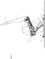
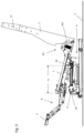
Fig. 1 shows a piece of seating furniture according to the invention in its upright basic position. Essentially only the mechanics are shown, so that in particular padding and side bolsters have been omitted to better explain the invention. The seating furniture has aseat 1, abackrest 2 and afootrest 3. Furthermore, abase frame 4 is provided for supporting the seating furniture on a standingsurface 5. - By actuating an
actuator 6 in a first (rotational) direction, a stand-upaid 7 is activated for lifting theseat 1 and thebackrest 2 from the upright basic position according toFig. 1 to a raised position according toFig. 2 . If theactuator 6 is actuated in a second, opposite (rotational) direction starting from the upright basic position according toFig. 1 , afootrest adjustment mechanism 8 is activated for extending thefootrest 3 into the position shown inFig. 3 . Possibly, the front end of theseat 1 is also slightly raised. A further actuation of theactuator 6 in the second direction activates aseat adjustment mechanism 91 and abackrest adjustment mechanism 92, whereby theseat 1 and thebackrest 2 are adjusted into the reclined position shown inFig. 4 . - Starting from the reclined position shown in
Fig. 4 , a further actuation of theactuator 6 in the second direction causes the actuation of atilting mechanism 10, whereby theseat 1 andbackrest 2 are tilted into the tilted position shown inFig. 5 . Thetilting mechanism 10 causes thefootrest 3 to be raised and aheadrest 21 integrated in or separate from thebackrest 2 to be lowered with respect to the standingsurface 5. - The
base frame 4 is described in more detail below with reference toFig. 4 ,5 and6 . It consists essentially of afirst frame part 41 and asecond frame part 42, which are hingedly connected to one another around atransverse axis 43. Thebase frame 4 also has afastening flange 44 which is fixedly arranged in a central region of thefirst frame part 41 and extends upward from the standingsurface 5. - Furthermore, the
first frame part 41 provides two front supportingfeet 45, tworear supporting feet 46 and tworear standing rollers 47, thebase frame 4 being supported in the raised position, in the upright basic position and in the reclined position on thefront supporting feet 45 and therear standing rollers 47 of the first frame part. Thesecond frame part 42, on the other hand, only hasfront standing rollers 48, which are only used during the tilting process, so that the base frame is supported in the tilted position according toFig. 5 on the front standingrollers 48 of thesecond frame part 42 and therear supporting feet 46 of thefirst frame part 41 on the standingarea 5. Therear standing rollers 47 of thefirst frame part 41 are therefore fastened between the front supportingfeet 45 and therear supporting feet 46 on thefirst frame part 41. Therear supporting feet 46 define the pivot point about which the seating furniture tilts backwards during the tilting process. Thefront standing rollers 48 of thesecond frame part 42 roll on the standingsurface 5 during the tilting process. - The
base frame 4 also has aswivel frame 49, which is shown in more detail inFig. 7a to 8b . It essentially consists of two lateral swivel levers 491, 492 parallel to each other which are articulated at one end about acommon hinge axis 497 on the mountingflange 44 of thefirst frame part 41. In a central area, the twoswivel levers cross-member 494. At the ends of the swivel levers 491, 492 opposite thehinge axis 497, ashaft 493 extending transversely to the pivot levers 491, 492 is rotatably articulated, on which acoupling arm 495 is rotatably attached approximately in the middle. - In the embodiment shown, the
actuator 6 is designed as a linear motor with anut 62 which can be linearly adjusted via aspindle 61. At the end of theactuator 6 on the motor side, acoupling eye 63 is provided, with which theactuator 6 is hingedly connected to thecoupling arm 495 about asecond hinge axis 498. Thenut 62 is coupled to theseat 1 via a connectingelement 11. - The various positions according to
Fig. 1 to 5 are each achieved by moving thenut 62 along thespindle 61. In other words, each position of the seating furniture is defined by a characteristic distance between thecoupling eyelet 63 or the secondjoint axis 498 and thenut 62. By actuating theactuator 6, thenut 62 can be moved along thespindle 61 to the respectively desired distance from thecoupling eyelet 63, in which the chair assumes the position assigned to the distance. When the actuator rotates in the first direction of rotation, the distance between thecoupling eyelet 63 and thenut 62 is shortened, while activation in the opposite second direction of rotation increases the distance. - In the upright basic position, the
nut 62 is in a central position on thespindle 61, in which it is at a distance a1 from thecoupling eyelet 63. If theactuator 6 is actuated in a first direction (direction of rotation of the spindle 61), thenut 62 moves in the direction of thecoupling eyelet 63 and thereby shortens the distance between thecoupling eyelet 63 andnut 62. This in turn activates the stand-up aid so that theseat 1 and thebackrest 2 move into the raised position according toFig. 2 . In this position, thenut 62 is only a distance a0 from thecoupling eyelet 23. During this actuation of theactuator 6, the connection of thenut 62 to theseat 1 via the connectingelement 11 acts as an abutment, so that a tensile force in the direction of the arrow 499 (Fig. 7a ) acts on thecoupling arm 495 in the region of thecoupling eyelet 63. After thecoupling arm 495 is non-rotatably connected to theshaft 493, this tensile force causes theshaft 493 to rotate clockwise until two first actuating levers 101, which are non-rotatably connected to theshaft 493, come into contact with afirst stop 500 and prevent further rotation of the shaft 493 (Fig. 7a and 7b ). - According to
Fig. 2 , the stand-upaid 7 is essentially formed by two liftingrods 71 and theswivel frame 49. For this purpose, the two liftingrods 71 are likewise articulated at the lower end to the twolateral fastening flanges 44 of thebase frame 4 so as to be pivotable about athird hinge axis 72. The upper ends of the liftingrods 71 are each articulated to alateral coupling element 12 about afourth articulation axis 73. Thefirst coupling elements 12 are laterally firmly connected to theseat 1 or an associated seat frame. After theswivel frame 49 is rotatable about thefirst hinge axis 497 and, on the other hand, is connected to theactuator 6 via thecoupling arm 495, a tensile force in the direction of thearrow 499 causes thelever linkage 71 and theswivel frame 49 to pivot about thethird hinge axis 72 or thefirst hinge axis 497 until the shortest distance a0 betweencoupling eyelet 63 andnut 62 according toFig. 2 is reached. Theseat 1 and thebackrest 2 are in a raised position compared to the upright basic position according toFig. 1 , in which raised position theseat 1 and thebackrest 2 are also equally tilted forward in order to facilitate standing up or sitting down. If theactuator 6, starting from the raised position according toFig. 2 , is actuated in the second opposite direction, the seating furniture initially assumes the upright basic position according toFig. 1 again. - Starting from the upright basic position according to
Fig. 1 , a further actuation of themotor 6 in the second direction causes a further displacement of thenut 62 in the sense of an increase in the distance between thenut 62 and thecoupling eyelet 63, which in turn initially actuates thefootrest adjustment mechanism 8, causing thefootrest 3 to extend. The footrest adjustment mechanism is designed, for example, in the manner of a scissor mechanism. The implementation of thefootrest 3 with the aid of thefootrest adjustment mechanism 8 is well known to those skilled in the art and is ultimately based on the fact that theseat 1 is at least moved backwards, thefootrest adjustment mechanism 8 connected to theseat 1 or theseat adjustment mechanism 91 causing thefootrest 3 to extend. The angle betweenseat 1 andbackrest 2 is hardly or not at all changed when thefootrest 3 is extended. - The
backrest 2 is coupled to the seat and the seat-adjustingmechanism 91 via abackrest adjustment mechanism 92. In the region of thebackrest adjustment mechanism 92,spring elements 921 are provided which initially only extend thefootrest 3 and do not yet adjust thebackrest 2 relative to theseat 1 when the actuator is activated from the upright basic position according toFig. 1 into the reclined position according toFig. 4 . Only when thefootrest 3 is extended and theactuator 6 is further actuated is thebackrest 2 adjusted against the force of thespring elements 921, in that the angle between theseat 1 and thebackrest 2 is increased by thebackrest adjustment mechanism 92. In addition, the front region of theseat 1 can be raised. - So that, starting from the reclined position according to
Fig. 4 , further actuation of the actuator in the sense of increasing the distance between thenut 62 and thecoupling eyelet 63 does not cause any further inclination of thebackrest 2 with respect to theseat 1, the backrest adjustment mechanism has a stop element 922 (Fig. 9 ), which blocks a further rotation of thebackrest 2 relative to theseat 1 between the reclined position according toFig. 4 and the tilted position according toFig. 5 . Thestop element 922 now causes theactuator 6 to exert a compressive force on thecoupling arm 495 in the direction of thearrow 501 so that theshaft 493 rotates counterclockwise inFig. 8a . - With this counterclockwise rotational movement, the
tilting mechanism 10 is triggered, which comprises thefirst actuating lever 101 and asecond actuating lever 102, which are each present on either side of the seating furniture. The two first actuating levers 101 are each connected non-rotatably to theshaft 493 of theswivel frame 49 at one end. At the other end of the first actuating levers 101, the second operating levers 102 are hingedly connected, which actuating levers are in turn hingedly connected at their other end to thesecond frame part 42, specifically at the end facing away from the front standingrollers 48. A counterclockwise rotation of theshaft 493 then causes a relative adjustment of thefirst frame part 41 with respect to thesecond frame part 42 about thetransverse axis 43, the twoframe parts Fig. 5 ). Thefirst frame part 41 is supported on itsrear supporting feet 46 on the standingsurface 5 and form the tilting axis around which the seating furniture is tilted. Thefront standing rollers 48 of the second frame part roll on the standingsurface 5 during the tilting process in the sense of a shortening of the distance between the rear (stationary) supportingfeet 46 and the front standingrollers 48. Starting from the reclined position according toFig. 4 , thefootrest 3, theseat 1 and thebackrest 2 are tilted backwards as a unit during the tilting process, so that thefootrest 3 is raised and theheadrest 21 is lowered relative to the standingsurface 5. - If the motor is reversed in its direction of rotation, starting from the tilted position according to
Fig. 5 , the reclined position according toFig. 4 is first reached before thefootrest 3 is retracted and the upright basic position is reached again. - If the seating furniture is adjusted without loading by a person, the
spring element 921 can cause theshaft 493 to rotate in the direction of thearrow 501 before thebackrest 2 is inclined relative to theseat 1. In order to prevent theshaft 493 from being rotated beyond a maximum rotational position by theactuator 6 and thereby damaging the motor, asecond stop 13 can be provided on theseat 1 or on theseat adjustment mechanism 91 or at another suitable point (Fig. 6 ), which blocks the rotation of theshaft 493 until the seating furniture has reached the reclined position shown inFig. 4 .
Claims (8)
- Seating furniture comprisinga. a seat (1),b. a backrest (2) having an integrated or separate headrest (21),c. a seat-backrest adjustment mechanism (91, 92) for adjusting the seat (1) and the backrest (2) from an upright initial position to a reclined position,d. a footrest (3) having a footrest adjustment mechanism (8) for extending and retracting the footrest (3),e. a base frame (4) for supporting the seating furniture on a standing surface (5), wherein the base frame (4) comprises a tilting mechanism (10) for tilting the seating furniture,f. a stand-up aid (7) for raising the seat (1) and the backrest (2) from the upright initial position to a raised position,g. an actuator (6) for actuating the seat/backrest adjustment mechanism (91, 92), the footrest adjustment mechanism, the tilting mechanism (10) and the stand-up aid (7), whereing1. - starting from the upright initial position, actuation of the actuator (6) in a first direction activates the stand-up aid (7),g2. - starting from the upright initial position, actuation of the actuator (6) in a second (opposite) direction activates the footrest adjustment mechanism (8) for extending the footrest and activates the seat-backrest adjustment mechanism (91, 92) for adjusting the seat (1) and the backrest (2) to the reclined position, andg3. - starting from the reclined position - a further actuation of the actuator (6) in the second direction causes an actuation of the tilting mechanism (10) for tilting the seat (1) and backrest (2) into a tilted position, the tilting mechanism (10) raising the footrest (3) and lowering the backrest (2) relative to the standing surface (5),characterized in thatthe base frame (4) has a first frame part (41) and a second frame part (42) which are hingedly connected to one another about a transverse axis (43) and the tilting mechanism (10) being designed for relative adjustment of the first frame part (41) and the second frame part (42) around the transverse axis (43) andthe seat-backrest adjustment mechanism (91, 92) has a stop element (922) that blocks further rotation of the backrest (2) relative to the seat (1) between the reclined position and the tilted position, so that the angle between seat (1) and backrest (2) in the reclined position is the same as in the tilted position.
- Seating furniture according to claim 1, characterized in that the actuator (6) is designed as a linear actuator which is coupled at a first end to the base frame and at a second end to the seat (1).
- Seating furniture according to claim 1, characterized in that the base frame (4) has a rotatably mounted shaft (493) extending transversely to the seating furniture and the actuator (6) is coupled with a first end to the shaft (493) for rotating the same.
- Seating furniture according to claim 3, characterized in that, when the actuator (6) is actuated in the first direction, the shaft (493) is rotated as far as a first stop (500), which blocks further rotation of the shaft (493) such that further actuation of the actuator (6) in the first direction activates the stand-up aid (7) for raising the seat (1) and the backrest (2) into the raised position.
- Seating furniture according to claim 4, , characterized in that a second stop (13) is provided which is connected to the seat (1) or to the seat-backrest adjustment mechanism (91, 92) and which blocks further rotation of the shaft (493) in the event of active contact with the shaft (493) when the actuator (6) is actuated in the second direction.
- Seating furniture according to claim 3, characterized in that the tilting mechanism (10) has at least one lever linkage, one end of which is non-rotatably attached to the shaft (493) and the other end of which is hingedly coupled to the second frame part (42) of the base frame (4), with further actuation of the actuator (6) in the second direction, starting from the reclined position, leading to rotation of the shaft (493) and a resulting relative adjustment of the first and the second frame part (41, 42) about the transverse axis (43).
- Seating furniture according to claim 6, characterized in that the at least one lever linkage has a first actuating lever (101) and a second actuating lever (102), the first actuating lever (101) being non-rotatably attached at one end to the shaft (493) that is rotatably mounted on the first frame part (41) and being hingedly coupled at its other end to the second actuating lever (102), which in turn is hingedly connected to the second frame part (42) of the base frame (4).
- Seating furniture according to claim 1, characterized in that the first frame part (41) has two front supporting feet (45), two rear supporting feet (46) and two rear supporting rollers (47), the base frame (4) being supported on the front supporting feet and the rear supporting rollers (47) of the first frame part (41) in the raised position and in the reclined position, and the second frame part (42) has two front supporting rollers (48), the base frame (4) being supported in the reclined position on the front supporting rollers (47) of the second frame part (42) and the rear supporting feet (46) of the first frame part (41) on the standing surface (5).
Applications Claiming Priority (1)
| Application Number | Priority Date | Filing Date | Title |
|---|---|---|---|
| DE202020106464.9U DE202020106464U1 (en) | 2020-11-11 | 2020-11-11 | Seating furniture with stand-up aid |
Publications (3)
| Publication Number | Publication Date |
|---|---|
| EP4000573A1 EP4000573A1 (en) | 2022-05-25 |
| EP4000573C0 EP4000573C0 (en) | 2025-06-11 |
| EP4000573B1 true EP4000573B1 (en) | 2025-06-11 |
Family
ID=74092957
Family Applications (1)
| Application Number | Title | Priority Date | Filing Date |
|---|---|---|---|
| EP21202645.4A Active EP4000573B1 (en) | 2020-11-11 | 2021-10-14 | Seating furniture with stand-up aid |
Country Status (5)
| Country | Link |
|---|---|
| EP (1) | EP4000573B1 (en) |
| CN (1) | CN114532782B (en) |
| DE (1) | DE202020106464U1 (en) |
| ES (1) | ES3034604T3 (en) |
| PL (1) | PL4000573T3 (en) |
Citations (1)
| Publication number | Priority date | Publication date | Assignee | Title |
|---|---|---|---|---|
| US9241855B2 (en) * | 2012-09-12 | 2016-01-26 | La-Z-Boy Incorporated | Furniture member and power recline and lift mechanism |
Family Cites Families (7)
| Publication number | Priority date | Publication date | Assignee | Title |
|---|---|---|---|---|
| DE20000926U1 (en) * | 2000-01-20 | 2000-03-16 | Stanzwerk Wetter Sichelschmidt GmbH & Co. KG, 58300 Wetter | Armchair with stand-up aid |
| DE202006016889U1 (en) * | 2006-11-04 | 2007-01-04 | Stanzwerk Wetter Sichelschmidt Gmbh & Co. Kg | Chair has reclining back and extending foot rest which are operated by spindle driven by electric motor, nut mounted on this moving lever, on which foot rest is mounted |
| US9357847B2 (en) * | 2014-09-26 | 2016-06-07 | Ultra-Mek, Inc. | Reclining seating unit with power actuators |
| US9655450B2 (en) * | 2015-03-17 | 2017-05-23 | La-Z-Boy Incorporated | Wall proximity furniture member reclining mechanism |
| EP3537930A4 (en) * | 2016-12-12 | 2020-07-22 | Ultra-mek, Inc. | POWER SUPPORT TILTABLE LIFT WITH DIVIDED SEAT |
| DE202017103410U1 (en) * | 2017-06-07 | 2017-07-05 | Ciar S.P.A. | Seating and reclining furniture |
| DE202019100213U1 (en) * | 2019-01-15 | 2019-01-31 | Ciar S.P.A. | armchair |
-
2020
- 2020-11-11 DE DE202020106464.9U patent/DE202020106464U1/en active Active
-
2021
- 2021-10-14 EP EP21202645.4A patent/EP4000573B1/en active Active
- 2021-10-14 ES ES21202645T patent/ES3034604T3/en active Active
- 2021-10-14 PL PL21202645.4T patent/PL4000573T3/en unknown
- 2021-11-10 CN CN202111325116.9A patent/CN114532782B/en active Active
Patent Citations (1)
| Publication number | Priority date | Publication date | Assignee | Title |
|---|---|---|---|---|
| US9241855B2 (en) * | 2012-09-12 | 2016-01-26 | La-Z-Boy Incorporated | Furniture member and power recline and lift mechanism |
Also Published As
| Publication number | Publication date |
|---|---|
| EP4000573C0 (en) | 2025-06-11 |
| PL4000573T3 (en) | 2025-08-04 |
| EP4000573A1 (en) | 2022-05-25 |
| ES3034604T3 (en) | 2025-08-20 |
| CN114532782A (en) | 2022-05-27 |
| DE202020106464U1 (en) | 2020-12-02 |
| CN114532782B (en) | 2025-07-04 |
Similar Documents
| Publication | Publication Date | Title |
|---|---|---|
| CN1893857B (en) | Adjustable reclining seat | |
| US9016788B1 (en) | Lift chair and recliner | |
| CA3046631C (en) | Power-assisted reclining lift chair with split seat | |
| US20010035668A1 (en) | Power actuated reclining chair with wall-hugger function | |
| CN112867421A (en) | Over-armrest pivoting recliner mechanism for seat unit and modular seat unit connection system | |
| EP3682860B1 (en) | Armchair | |
| US10729246B2 (en) | Person support apparatus with shear-reducing pivot assembly | |
| EP3949808B1 (en) | Seating and reclining furniture | |
| CN101102700A (en) | armchair | |
| JP2001526556A (en) | Adjustment devices for beds and other furniture for reclining or sitting | |
| GB2380399A (en) | Power operated lift reclining chair | |
| EP4000573A1 (en) | Seating furniture with stand-up aid | |
| JP2000508192A (en) | Furniture adjustment equipment | |
| CN113208336A (en) | Seat surface inclination angle adjusting structure and leisure chair | |
| JP4154934B2 (en) | Massage chair | |
| JP2002136377A (en) | Leg-less chair | |
| GB2307213A (en) | Transfer system for persons | |
| JPS6223479Y2 (en) | ||
| JP2002136381A (en) | Legless chair | |
| WO1999018822A2 (en) | Improvements in or relating to chairs | |
| JP2002136382A (en) | Legless chair | |
| JPH11128014A (en) | Chair |
Legal Events
| Date | Code | Title | Description |
|---|---|---|---|
| PUAI | Public reference made under article 153(3) epc to a published international application that has entered the european phase |
Free format text: ORIGINAL CODE: 0009012 |
|
| STAA | Information on the status of an ep patent application or granted ep patent |
Free format text: STATUS: THE APPLICATION HAS BEEN PUBLISHED |
|
| AK | Designated contracting states |
Kind code of ref document: A1 Designated state(s): AL AT BE BG CH CY CZ DE DK EE ES FI FR GB GR HR HU IE IS IT LI LT LU LV MC MK MT NL NO PL PT RO RS SE SI SK SM TR |
|
| STAA | Information on the status of an ep patent application or granted ep patent |
Free format text: STATUS: REQUEST FOR EXAMINATION WAS MADE |
|
| 17P | Request for examination filed |
Effective date: 20220706 |
|
| RBV | Designated contracting states (corrected) |
Designated state(s): AL AT BE BG CH CY CZ DE DK EE ES FI FR GB GR HR HU IE IS IT LI LT LU LV MC MK MT NL NO PL PT RO RS SE SI SK SM TR |
|
| STAA | Information on the status of an ep patent application or granted ep patent |
Free format text: STATUS: EXAMINATION IS IN PROGRESS |
|
| 17Q | First examination report despatched |
Effective date: 20230928 |
|
| GRAP | Despatch of communication of intention to grant a patent |
Free format text: ORIGINAL CODE: EPIDOSNIGR1 |
|
| STAA | Information on the status of an ep patent application or granted ep patent |
Free format text: STATUS: GRANT OF PATENT IS INTENDED |
|
| INTG | Intention to grant announced |
Effective date: 20250326 |
|
| GRAS | Grant fee paid |
Free format text: ORIGINAL CODE: EPIDOSNIGR3 |
|
| GRAA | (expected) grant |
Free format text: ORIGINAL CODE: 0009210 |
|
| STAA | Information on the status of an ep patent application or granted ep patent |
Free format text: STATUS: THE PATENT HAS BEEN GRANTED |
|
| AK | Designated contracting states |
Kind code of ref document: B1 Designated state(s): AL AT BE BG CH CY CZ DE DK EE ES FI FR GB GR HR HU IE IS IT LI LT LU LV MC MK MT NL NO PL PT RO RS SE SI SK SM TR |
|
| REG | Reference to a national code |
Ref country code: GB Ref legal event code: FG4D |
|
| REG | Reference to a national code |
Ref country code: CH Ref legal event code: EP |
|
| REG | Reference to a national code |
Ref country code: IE Ref legal event code: FG4D |
|
| REG | Reference to a national code |
Ref country code: DE Ref legal event code: R096 Ref document number: 602021032038 Country of ref document: DE |
|
| U01 | Request for unitary effect filed |
Effective date: 20250611 |
|
| U07 | Unitary effect registered |
Designated state(s): AT BE BG DE DK EE FI FR IT LT LU LV MT NL PT RO SE SI Effective date: 20250620 |
|
| REG | Reference to a national code |
Ref country code: ES Ref legal event code: FG2A Ref document number: 3034604 Country of ref document: ES Kind code of ref document: T3 Effective date: 20250820 |
|
| PG25 | Lapsed in a contracting state [announced via postgrant information from national office to epo] |
Ref country code: NO Free format text: LAPSE BECAUSE OF FAILURE TO SUBMIT A TRANSLATION OF THE DESCRIPTION OR TO PAY THE FEE WITHIN THE PRESCRIBED TIME-LIMIT Effective date: 20250911 Ref country code: GR Free format text: LAPSE BECAUSE OF FAILURE TO SUBMIT A TRANSLATION OF THE DESCRIPTION OR TO PAY THE FEE WITHIN THE PRESCRIBED TIME-LIMIT Effective date: 20250912 |
|
| PGFP | Annual fee paid to national office [announced via postgrant information from national office to epo] |
Ref country code: PL Payment date: 20250929 Year of fee payment: 5 |
|
| PG25 | Lapsed in a contracting state [announced via postgrant information from national office to epo] |
Ref country code: HR Free format text: LAPSE BECAUSE OF FAILURE TO SUBMIT A TRANSLATION OF THE DESCRIPTION OR TO PAY THE FEE WITHIN THE PRESCRIBED TIME-LIMIT Effective date: 20250611 |
|
| PG25 | Lapsed in a contracting state [announced via postgrant information from national office to epo] |
Ref country code: RS Free format text: LAPSE BECAUSE OF FAILURE TO SUBMIT A TRANSLATION OF THE DESCRIPTION OR TO PAY THE FEE WITHIN THE PRESCRIBED TIME-LIMIT Effective date: 20250911 |
|
| U20 | Renewal fee for the european patent with unitary effect paid |
Year of fee payment: 5 Effective date: 20251001 |
|
| PG25 | Lapsed in a contracting state [announced via postgrant information from national office to epo] |
Ref country code: IS Free format text: LAPSE BECAUSE OF FAILURE TO SUBMIT A TRANSLATION OF THE DESCRIPTION OR TO PAY THE FEE WITHIN THE PRESCRIBED TIME-LIMIT Effective date: 20251011 |
|
| PG25 | Lapsed in a contracting state [announced via postgrant information from national office to epo] |
Ref country code: SM Free format text: LAPSE BECAUSE OF FAILURE TO SUBMIT A TRANSLATION OF THE DESCRIPTION OR TO PAY THE FEE WITHIN THE PRESCRIBED TIME-LIMIT Effective date: 20250611 |
|
| PG25 | Lapsed in a contracting state [announced via postgrant information from national office to epo] |
Ref country code: CZ Free format text: LAPSE BECAUSE OF FAILURE TO SUBMIT A TRANSLATION OF THE DESCRIPTION OR TO PAY THE FEE WITHIN THE PRESCRIBED TIME-LIMIT Effective date: 20250611 |
|
| PG25 | Lapsed in a contracting state [announced via postgrant information from national office to epo] |
Ref country code: SK Free format text: LAPSE BECAUSE OF FAILURE TO SUBMIT A TRANSLATION OF THE DESCRIPTION OR TO PAY THE FEE WITHIN THE PRESCRIBED TIME-LIMIT Effective date: 20250611 |
|
| PGFP | Annual fee paid to national office [announced via postgrant information from national office to epo] |
Ref country code: ES Payment date: 20251216 Year of fee payment: 5 |
|
| PLBE | No opposition filed within time limit |
Free format text: ORIGINAL CODE: 0009261 |
|
| STAA | Information on the status of an ep patent application or granted ep patent |
Free format text: STATUS: NO OPPOSITION FILED WITHIN TIME LIMIT |
|
| REG | Reference to a national code |
Ref country code: CH Ref legal event code: L10 Free format text: ST27 STATUS EVENT CODE: U-0-0-L10-L00 (AS PROVIDED BY THE NATIONAL OFFICE) Effective date: 20260423 |