EP3682860B1 - Armchair - Google Patents
Armchair Download PDFInfo
- Publication number
- EP3682860B1 EP3682860B1 EP20151614.3A EP20151614A EP3682860B1 EP 3682860 B1 EP3682860 B1 EP 3682860B1 EP 20151614 A EP20151614 A EP 20151614A EP 3682860 B1 EP3682860 B1 EP 3682860B1
- Authority
- EP
- European Patent Office
- Prior art keywords
- armchair
- chassis
- adjustment mechanism
- footprint
- seat
- Prior art date
- Legal status (The legal status is an assumption and is not a legal conclusion. Google has not performed a legal analysis and makes no representation as to the accuracy of the status listed.)
- Active
Links
- 238000005096 rolling process Methods 0.000 claims description 5
- 238000006073 displacement reaction Methods 0.000 claims description 4
- 230000008878 coupling Effects 0.000 description 24
- 238000010168 coupling process Methods 0.000 description 24
- 238000005859 coupling reaction Methods 0.000 description 24
- 235000004443 Ricinus communis Nutrition 0.000 description 4
- 240000000528 Ricinus communis Species 0.000 description 4
- 210000001364 upper extremity Anatomy 0.000 description 2
- 230000004913 activation Effects 0.000 description 1
- 239000011248 coating agent Substances 0.000 description 1
- 238000000576 coating method Methods 0.000 description 1
- 238000010276 construction Methods 0.000 description 1
- 230000003014 reinforcing effect Effects 0.000 description 1
- 238000004904 shortening Methods 0.000 description 1
- 210000002105 tongue Anatomy 0.000 description 1
Images


Classifications
-
- A—HUMAN NECESSITIES
- A47—FURNITURE; DOMESTIC ARTICLES OR APPLIANCES; COFFEE MILLS; SPICE MILLS; SUCTION CLEANERS IN GENERAL
- A47C—CHAIRS; SOFAS; BEDS
- A47C1/00—Chairs adapted for special purposes
- A47C1/02—Reclining or easy chairs
- A47C1/031—Reclining or easy chairs having coupled concurrently adjustable supporting parts
- A47C1/034—Reclining or easy chairs having coupled concurrently adjustable supporting parts the parts including a leg-rest or foot-rest
- A47C1/035—Reclining or easy chairs having coupled concurrently adjustable supporting parts the parts including a leg-rest or foot-rest in combination with movably coupled seat and back-rest, i.e. the seat and back-rest being movably coupled in such a way that the extension mechanism of the foot-rest is actuated at least by the relative movements of seat and backrest
- A47C1/0355—Reclining or easy chairs having coupled concurrently adjustable supporting parts the parts including a leg-rest or foot-rest in combination with movably coupled seat and back-rest, i.e. the seat and back-rest being movably coupled in such a way that the extension mechanism of the foot-rest is actuated at least by the relative movements of seat and backrest actuated by linkages, e.g. lazy-tongs mechanisms
-
- A—HUMAN NECESSITIES
- A61—MEDICAL OR VETERINARY SCIENCE; HYGIENE
- A61G—TRANSPORT, PERSONAL CONVEYANCES, OR ACCOMMODATION SPECIALLY ADAPTED FOR PATIENTS OR DISABLED PERSONS; OPERATING TABLES OR CHAIRS; CHAIRS FOR DENTISTRY; FUNERAL DEVICES
- A61G5/00—Chairs or personal conveyances specially adapted for patients or disabled persons, e.g. wheelchairs
- A61G5/10—Parts, details or accessories
- A61G5/14—Standing-up or sitting-down aids
-
- A—HUMAN NECESSITIES
- A47—FURNITURE; DOMESTIC ARTICLES OR APPLIANCES; COFFEE MILLS; SPICE MILLS; SUCTION CLEANERS IN GENERAL
- A47C—CHAIRS; SOFAS; BEDS
- A47C1/00—Chairs adapted for special purposes
- A47C1/02—Reclining or easy chairs
- A47C1/031—Reclining or easy chairs having coupled concurrently adjustable supporting parts
- A47C1/034—Reclining or easy chairs having coupled concurrently adjustable supporting parts the parts including a leg-rest or foot-rest
-
- A—HUMAN NECESSITIES
- A47—FURNITURE; DOMESTIC ARTICLES OR APPLIANCES; COFFEE MILLS; SPICE MILLS; SUCTION CLEANERS IN GENERAL
- A47C—CHAIRS; SOFAS; BEDS
- A47C1/00—Chairs adapted for special purposes
- A47C1/02—Reclining or easy chairs
- A47C1/022—Reclining or easy chairs having independently-adjustable supporting parts
- A47C1/024—Reclining or easy chairs having independently-adjustable supporting parts the parts, being the back-rest, or the back-rest and seat unit, having adjustable and lockable inclination
- A47C1/0242—Reclining or easy chairs having independently-adjustable supporting parts the parts, being the back-rest, or the back-rest and seat unit, having adjustable and lockable inclination by electric motors
-
- A—HUMAN NECESSITIES
- A47—FURNITURE; DOMESTIC ARTICLES OR APPLIANCES; COFFEE MILLS; SPICE MILLS; SUCTION CLEANERS IN GENERAL
- A47C—CHAIRS; SOFAS; BEDS
- A47C1/00—Chairs adapted for special purposes
- A47C1/02—Reclining or easy chairs
- A47C1/031—Reclining or easy chairs having coupled concurrently adjustable supporting parts
- A47C1/032—Reclining or easy chairs having coupled concurrently adjustable supporting parts the parts being movably-coupled seat and back-rest
- A47C1/03205—Reclining or easy chairs having coupled concurrently adjustable supporting parts the parts being movably-coupled seat and back-rest having adjustable and lockable inclination
- A47C1/03211—Reclining or easy chairs having coupled concurrently adjustable supporting parts the parts being movably-coupled seat and back-rest having adjustable and lockable inclination by electric motors
-
- A—HUMAN NECESSITIES
- A47—FURNITURE; DOMESTIC ARTICLES OR APPLIANCES; COFFEE MILLS; SPICE MILLS; SUCTION CLEANERS IN GENERAL
- A47C—CHAIRS; SOFAS; BEDS
- A47C7/00—Parts, details, or accessories of chairs or stools
- A47C7/50—Supports for the feet or the legs coupled to fixed parts of the chair
- A47C7/506—Supports for the feet or the legs coupled to fixed parts of the chair of adjustable type
-
- A—HUMAN NECESSITIES
- A47—FURNITURE; DOMESTIC ARTICLES OR APPLIANCES; COFFEE MILLS; SPICE MILLS; SUCTION CLEANERS IN GENERAL
- A47C—CHAIRS; SOFAS; BEDS
- A47C7/00—Parts, details, or accessories of chairs or stools
- A47C7/54—Supports for the arms
Definitions
- the invention relates to an armchair with a stand-up aid.
- an armchair with a stand-up aid is that the armchair can be very easily tilted forward using a remote control or a control knob, thus enabling the user to lift himself very comfortably out of the cushions.
- This functionality is particularly easy on the back, since no sudden effort is required when standing up.
- this mechanism also makes it possible to sit down in a particularly gentle and comfortable manner.
- Such armchairs are often embodied as so-called reclining chairs, which also offer the opportunity to tilt the backrest and extend a footrest.
- One or more servomotors are used to move the armchair into the various positions, with the consequence that the weight of such armchairs can be substantial.
- the armchair thus inevitably requires castors in order to be moved easily to another location.
- the wheels can be fixed in order to reliably prevent it from rolling away, especially when the stand-up aid is activated.
- JP H08 38296 A relates to an armchair with a seat, supporting feet, a lifting device and a chassis with wheels for moving the armchair.
- the chassis is adjustable via a first actuator relative to the supporting feet between at least a first and a second position, with the wheels being spaced apart in the first position of the footprint while the armchair is supported with the supporting feet on the footprint, and with the wheels being in rolling contact with the footprint in the second position while the supporting feet are arranged so as to be spaced apart from the footprint.
- the lifting device has a second actuator for moving the seat into a desirable height.
- US 2014/0138995 A1 discloses a chair with a seat having a front portion and a rear portion and being so constructed that as the seat moves towards a standing position, the rear portion of the seat remains substantially horizontally so a user does not slide out of the seat.
- the chair comprises front legs and rear legs each having an upper end and a lower end, with both pairs of legs connected at their upper ends to the front portion of the seat.
- the front legs can be adapted to telescope, and the lower end of each leg can have a wheel.
- An armchair with a stand-up aid is known from WO 96/39895 A that is supported in a home position by four wheels on the footprint.
- an anti-slip element is extended to the footprint by means of a lifting linkage, which raises the front wheels while being simultaneously supported on the footprint, thus ensuring a fixed positioning of the armchair.
- at least some rollers are equipped with a brake.
- the invention is based on the object of improving the armchair with stand-up aid in terms of its ease of use.
- the provision of supporting feet ensures that the armchair stands securely when the supporting feet are supported on the footprint.
- the wheels of the chassis come into rolling contact with the footprint, thus enabling the armchair to be easily moved to another location. It is not necessary for brakes on the rollers to be additionally released for this purpose.
- the retraction and raising of the chassis also has the advantage that the wheels do not tarnish the overall aesthetic appearance of the armchair when they are not needed.
- chassis is coupled with the servomotor via the adjustment mechanism for the motorized displacement of the chassis into the first, second, and third position.
- the seat has a seat frame mechanism that is fixed to side walls of the armchair.
- the adjustment mechanism can have at least one first lifting linkage and one second lifting linkage, in which case the first lifting linkage is hingedly coupled at a first end with the chassis and at a second end with the seat frame mechanism, and the second lifting linkage is also hingedly connected at a first end to the chassis, whereas the second end is in operative contact with the servomotor.
- the servomotor can thus be utilized both for the stand-up and for the operation of the chassis.
- At least one additional, articulated interlink can be provided between the second end of the second lifting linkage and the servomotor, which enables the motion sequences to be improved. It is especially advantageous if the linkage mechanism of the anti-slip element is hingedly coupled with the first lifting linkage of the adjustment mechanism.
- the armchair advantageously also has a footrest that is connected to the seat frame mechanism via a footrest adjustment mechanism for extending and retracting the footrest. Furthermore, a backrest is provided that can be adjusted with a backrest adjustment mechanism in order to move the seat and backrest between an upright home position and a reclined position. If, in addition, the footrest adjustment mechanism and the backrest adjustment mechanism are coupled with the servomotor, both the reclined position and the home position, as well as the stand-up aid and the extension of the chassis can be implemented in an especially cost-effective manner with one and the same motor.
- Fig. 1 shows the armchair according to the invention in its reclined position. It has a seat 1, a backrest 2, and a footrest 3.
- the armchair also provides for two side walls 4 that laterally bound the seat 1 and also serve as armrests.
- the armchair has front and rear supporting feet 5, 6, with which the armchair is supported on a footprint 7 in the depicted reclined position.
- the seat 1 also has a seat frame mechanism 8 with which are coupled a footrest adjustment mechanism 9 for extending and retracting the footrest 3 and a backrest adjustment mechanism 10 for adjusting the seat 1 and backrest 2 between an upright home position and the reclined relaxed position shown in Fig. 1 .
- the upholstery of the seat and footrest have been omitted in the illustration in order to better depict the armchair mechanics.
- Figs. 2 and 3 show three-dimensional representations of the armchair mechanics from different perspectives. It consists essentially of the seat frame mechanism 8, the footrest adjustment mechanism 9, and the backrest adjustment mechanism 10. A chassis 11 with front wheels 12 and rear wheels 13 is also provided. For motorized actuation of the armchair mechanics, a linear actuator with a servomotor 14 is provided. All of the armchair mechanics are bolted to the side walls 4 by means of two side plates 15 of the seat frame mechanism 8. The backrest, in turn, is fixed to two backrest support elements 16 of the backrest adjustment mechanism 10.
- the linear actuator has a spindle 17 and a nut 18 that cooperates with the spindle 17.
- the servomotor 14 rotates the spindle in the respectively desired direction of rotation, thus causing a linear displacement of the nut 18 along the spindle.
- the seat frame mechanism 8 has two laterally opposing seat frame parts 19, 20 to which the actual seat 2 is fastened along with its upholstery.
- the seat frame parts 19, 20 are rigidly interconnected by means of a first cross-brace 21 and a second cross-brace 22, with the first cross-brace 21 having two tongues 23, 24 that are arranged in a torque-proof manner in the center thereof and hingedly coupled with the nut 18 ( Fig. 3 ).
- a coupling lug 25 is provided for coupling an adjustment mechanism 26, which will be explained in greater detail below with reference to Figs. 4 to 8 , which show different positions of the armchair that can be achieved through displacement of the nut 18 along the spindle 17.
- each position of the armchair is defined by a characteristic distance between the coupling lug 25 and the nut 18.
- the nut 18 assumes the greatest distance a1 from the coupling lug 25.
- An actuation of the servomotor so as to shorten this distance causes a retraction of the footrest and an adjustment of the seat 1 and backrest 2 into an upright home position.
- the design of the seat mechanism that is required for this purpose is well known to a person skilled in the art, so it will not be discussed in any more detail below.
- the upright home position of the seat mechanism is shown in Fig. 4 .
- the backrest 2 and the footrest 3 as well as the footrest adjustment mechanism 9 have been omitted here.
- the distance between the nut 18 of the coupling lug 25 is now only a2.
- the chassis 11 is in a first, retracted or raised position in which the front wheels 12 and the rear wheels 13 are arranged so as to be spaced apart from the footprint 7.
- the wheels 12, 13 can be concealed such that possibly only the supporting feet 5, 6 are visible.
- the chassis 11 is lowered onto the footprint 7, so that both the supporting feet 5, 6 as well as the front wheels 12 and the rear wheels 13 are in contact with the footprint 7.
- the seat mechanism causes a lifting of the supporting feet 5, 6, so that the armchair is supported on the footprint 7 only on the wheels 12, 13 of the chassis 11.
- This second position of the chassis also represents the moving position of the armchair in which the armchair can be easily moved using the wheels.
- the rear wheels 13 are embodied as castors so that they can rotate about a vertical axis.
- an anti-slip element 27 is lowered onto the contact surface 7 by means of a linkage mechanism 28. If the distance between nut 18 and coupling lug 25 is then reduced even further, the stand-up auxiliary function is activated by lifting the seat into a raised and forward-inclined position according to Fig. 8 .
- the resulting distance a6 represents the smallest distance between the nut 18 and coupling lug 25.
- the shortening of the distance a5 to the distance a6 thus causes a further extension of the anti-slip element 27, so that the rear wheels 13 lift off the footprint 7 while the front wheels 12 remain in contact with the footprint 7 and thus form a swivel axis for the chassis 11.
- the seat 1 In the raised position according to Fig. 8 , the seat 1 has moved slightly upwards and inclined slightly forward, so that standing up or sitting down is made substantially easier for a user.
- the anti-slip element is provided with a suitable anti-slip coating that reliably ensures that the armchair stands securely and, in particular, does not inadvertently slip on the footprint 7.
- the front wheels 12 should not be embodied as castors.
- the configuration of the chassis 11 can be seen particularly well in Figs. 3 and 8 . It comprises substantially two lateral frame parts 29, 30, a rear cross-connecting part 31 and a front cross-connecting part 32, wherein the front wheels 12 being fastened to the front ends of the lateral frame parts 29, 30.
- Each of the rear wheels 13 is attached to first and second arms 33, 34, respectively, with the two arms each extending rearward from the rear cross-connecting part 31.
- two spaced-apart mounting flanges 35, 36 are further provided which are rigidly connected to the rear cross-connecting part 31 and provide a first coupling point 37 and a second coupling point 38, respectively, with which the adjustment mechanism 26 of the stand-up aid is hingedly coupled.
- this adjustment mechanism 26 has a first lifting linkage 39 and a second lifting linkage 40 on either side, respectively.
- the seat frame mechanism 8 also provides a first coupling element 41 and a second coupling element 42, each of which is rigidly connected to the first and second seat frame part 19, 20, respectively and to the second cross-brace 22, so that the two coupling elements 41, 42 project downward quasi obliquely from the first and second seat frame part, respectively.
- the first lifting linkage 39 is hinged on its first end at the first coupling point 37 of the mounting flange 35 or 36 and with its second end at a first articulation point 43 of the first and second coupling element 41, 42, respectively.
- the second lifting linkage 40 is hingedly connected at a first end to the second coupling point 38 of the mounting flange 35 and 36 and coupled in a central region with a second articulation point 44 of the first and second coupling element 41, 42, respectively. Both the first lifting linkage 39 and the second lifting linkage 40 are thus provided on the sides of the armchair.
- the respective second ends of the second lifting linkages 40 are pivotally interconnected by means of a rod-like interlink 45, with the interlink 45 being hingedly coupled with the coupling lug 25 in a central region by means of two arms 46 that are connected in a torque-proof manner thereto.
- the first and second coupling elements 41, 42 have recesses 47 on their forward-facing front edges that come into contact with the rod-shaped interlink 45 during the lifting of the armchair between the positions shown in Figs. 7 and 8 shortly before completion of the movement, thus reinforcing the inclined movement of the seat forward in the further course of the movement.
- the illustrated linkage mechanism 28 consists substantially of a first linkage part 48, a second linkage part 49, and a third linkage part 50.
- a coupling plate 51 is fastened to the first arm 33 and the second arm 34, respectively, that provides a first articulation point 52 for the first linkage part 48 and a second articulation point 53 for the second linkage part 49.
- the first linkage part 48 is coupled at one end with the first articulation point 52 and at the second end with a third articulation point 54 on the anti-skid element.
- the second linkage part 49 is hingedly coupled with the coupling plate 51 in a central region at the second articulation point 53 and hingedly connected at a first end to a fourth articulation point 55 on the anti-slip element 27.
- the second end of the second linkage part 49 is hingedly coupled with the third linkage part 50 which, in turn, is hingedly connected at its other end to a fifth articulation point 56 to the first lifting linkage 39.
- the armchair mechanics described above thus require only one servomotor 14 to reach all of the positions of the armchair. As will readily be understood, however, it is not excluded from the scope of the invention for an additional motor to be provided in order to be able to approach additional positions of the armchair as desired.
- the armchair is adjusted by means of a remote control or a control panel that is recessed in the armrest, with only four buttons being ultimately required in order to move to the positions of the armchair that are relevant to the user.
- Figs. 5 and 7 do not represent independently approachable positions, but rather are assumed during the movement from the upright home position to the moving position or from the moving position to the raised position without pauses in the movement of the armchair.
- Fig. 9 shows an example of a simplified adjustment mechanism 26' with a simple design that is characterized in that the first lifting linkage 39 of the adjustment mechanism 26 is simply extended further at the first coupling point 27 on the mounting flange 35 and 36 and bent downwards, bearing the anti-slip element 27 on its end.
- This solution thus requires substantially fewer articulation points and components and is therefore more economical.
- One tradeoff, however, is that the chair moves slightly backward during the movement between the position shown in Fig. 7 and the position shown in Fig. 8 , since the distance between the front wheels 12 and the anti-slip element that is placed on the footprint 7 is shortened during the lifting operation.
Description
- The invention relates to an armchair with a stand-up aid.
- The advantage of an armchair with a stand-up aid is that the armchair can be very easily tilted forward using a remote control or a control knob, thus enabling the user to lift himself very comfortably out of the cushions. This functionality is particularly easy on the back, since no sudden effort is required when standing up. However, this mechanism also makes it possible to sit down in a particularly gentle and comfortable manner.
- Such armchairs are often embodied as so-called reclining chairs, which also offer the opportunity to tilt the backrest and extend a footrest. One or more servomotors are used to move the armchair into the various positions, with the consequence that the weight of such armchairs can be substantial. The armchair thus inevitably requires castors in order to be moved easily to another location. However, once the proper location for the armchair has been found, it is desirable if the wheels can be fixed in order to reliably prevent it from rolling away, especially when the stand-up aid is activated.
- Nonetheless, such castors are often aesthetically unappealing, for which reason other constructions have been considered in which the armchair is usually on supporting feet and a chassis can be extended only in the event that the armchair is to be moved. But this solution, too, requires additional investment in the upholstery in the region of the backrest in order to achieve satisfactory aesthetic impressions. In addition, the operation of the pedal requires a certain amount of force that cannot be mustered by older people in some circumstances. Last but not least, the chassis that can be extended by means of a foot pedal results in added costs.
-
JP H08 38296 A -
US 2014/0138995 A1 discloses a chair with a seat having a front portion and a rear portion and being so constructed that as the seat moves towards a standing position, the rear portion of the seat remains substantially horizontally so a user does not slide out of the seat. The chair comprises front legs and rear legs each having an upper end and a lower end, with both pairs of legs connected at their upper ends to the front portion of the seat. The front legs can be adapted to telescope, and the lower end of each leg can have a wheel. - An armchair with a stand-up aid is known from
WO 96/39895 A - The invention is based on the object of improving the armchair with stand-up aid in terms of its ease of use.
- According to the invention, this object is achieved by the features of
claim 1. - The provision of supporting feet ensures that the armchair stands securely when the supporting feet are supported on the footprint. Through activation of the servomotor, the wheels of the chassis come into rolling contact with the footprint, thus enabling the armchair to be easily moved to another location. It is not necessary for brakes on the rollers to be additionally released for this purpose. The retraction and raising of the chassis also has the advantage that the wheels do not tarnish the overall aesthetic appearance of the armchair when they are not needed.
- It is especially user-friendly that the chassis is coupled with the servomotor via the adjustment mechanism for the motorized displacement of the chassis into the first, second, and third position.
- Additional advantages and embodiments of the invention constitute the subject matter of the subclaims.
- According to another embodiment of the invention, the seat has a seat frame mechanism that is fixed to side walls of the armchair. Moreover, the adjustment mechanism can have at least one first lifting linkage and one second lifting linkage, in which case the first lifting linkage is hingedly coupled at a first end with the chassis and at a second end with the seat frame mechanism, and the second lifting linkage is also hingedly connected at a first end to the chassis, whereas the second end is in operative contact with the servomotor. The servomotor can thus be utilized both for the stand-up and for the operation of the chassis.
- According to another embodiment of the invention, at least one additional, articulated interlink can be provided between the second end of the second lifting linkage and the servomotor, which enables the motion sequences to be improved. It is especially advantageous if the linkage mechanism of the anti-slip element is hingedly coupled with the first lifting linkage of the adjustment mechanism.
- In addition to the stand-up aid and the possibility of moving the armchair by means of the wheels, the armchair advantageously also has a footrest that is connected to the seat frame mechanism via a footrest adjustment mechanism for extending and retracting the footrest. Furthermore, a backrest is provided that can be adjusted with a backrest adjustment mechanism in order to move the seat and backrest between an upright home position and a reclined position. If, in addition, the footrest adjustment mechanism and the backrest adjustment mechanism are coupled with the servomotor, both the reclined position and the home position, as well as the stand-up aid and the extension of the chassis can be implemented in an especially cost-effective manner with one and the same motor.
- Additional advantages and embodiments of the invention are explained in greater detail in the description of an exemplary embodiment and the drawing:
In the drawing: - Fig. 1
- shows a side view of the armchair according to the invention in the reclined position,
- Fig. 2
- shows a first three-dimensional representation of the armchair mechanics obliquely from the front,
- Fig. 3
- shows a second three-dimensional representation of the armchair mechanics obliquely from the rear,
- Fig. 4
- shows a simplified side view of the armchair according to the invention with the chassis raised,
- Fig. 5
- shows a simplified side view of the armchair according to the invention with the chassis lowered,
- Fig. 6
- shows a simplified side view of the armchair according to the invention in the moving position,
- Fig. 7
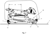
- shows a simplified side view of the armchair according to the invention in a position with lowered anti-slip element,
- Fig. 8
- shows a simplified side view of the armchair according to the invention in the raised position of the armchair (stand-up aid activated), and
- Fig. 9
- shows a simplified side view of the armchair according to the invention in the raised position of the armchair (stand-up aid activated) according to a second exemplary embodiment.
-
Fig. 1 shows the armchair according to the invention in its reclined position. It has aseat 1, abackrest 2, and afootrest 3. The armchair also provides for twoside walls 4 that laterally bound theseat 1 and also serve as armrests. Furthermore, the armchair has front and rear supportingfeet footprint 7 in the depicted reclined position. Theseat 1 also has aseat frame mechanism 8 with which are coupled afootrest adjustment mechanism 9 for extending and retracting thefootrest 3 and abackrest adjustment mechanism 10 for adjusting theseat 1 andbackrest 2 between an upright home position and the reclined relaxed position shown inFig. 1 . The upholstery of the seat and footrest have been omitted in the illustration in order to better depict the armchair mechanics. -
Figs. 2 and3 show three-dimensional representations of the armchair mechanics from different perspectives. It consists essentially of theseat frame mechanism 8, thefootrest adjustment mechanism 9, and thebackrest adjustment mechanism 10. Achassis 11 withfront wheels 12 andrear wheels 13 is also provided. For motorized actuation of the armchair mechanics, a linear actuator with aservomotor 14 is provided. All of the armchair mechanics are bolted to theside walls 4 by means of twoside plates 15 of theseat frame mechanism 8. The backrest, in turn, is fixed to twobackrest support elements 16 of thebackrest adjustment mechanism 10. - In addition to the
servomotor 14, the linear actuator has aspindle 17 and anut 18 that cooperates with thespindle 17. Theservomotor 14 rotates the spindle in the respectively desired direction of rotation, thus causing a linear displacement of thenut 18 along the spindle. - The
seat frame mechanism 8 has two laterally opposingseat frame parts actual seat 2 is fastened along with its upholstery. Theseat frame parts first cross-brace 21 and asecond cross-brace 22, with thefirst cross-brace 21 having twotongues Fig. 3 ). - At the motor end of the linear actuator, a
coupling lug 25 is provided for coupling anadjustment mechanism 26, which will be explained in greater detail below with reference toFigs. 4 to 8 , which show different positions of the armchair that can be achieved through displacement of thenut 18 along thespindle 17. In other words, each position of the armchair is defined by a characteristic distance between thecoupling lug 25 and thenut 18. By actuating theservomotor 14, thenut 18 can be moved along the spindle to the respective desired distance from thecoupling lug 25 at which the armchair assumes the position that is associated with the distance. - In the reclined position according to
Fig. 1 , thenut 18 assumes the greatest distance a1 from thecoupling lug 25. An actuation of the servomotor so as to shorten this distance causes a retraction of the footrest and an adjustment of theseat 1 andbackrest 2 into an upright home position. The design of the seat mechanism that is required for this purpose is well known to a person skilled in the art, so it will not be discussed in any more detail below. - The upright home position of the seat mechanism is shown in
Fig. 4 . For the sake of clarity, thebackrest 2 and thefootrest 3 as well as thefootrest adjustment mechanism 9 have been omitted here. In this position, the distance between thenut 18 of thecoupling lug 25 is now only a2. In this home position of the armchair, the armchair is supported by its supportingfeet footprint 7. On the other hand, thechassis 11 is in a first, retracted or raised position in which thefront wheels 12 and therear wheels 13 are arranged so as to be spaced apart from thefootprint 7. Through appropriate configuration of the armchair cover, thewheels feet - If the distance of the
nut 18 from thecoupling lug 25 is further shortened by means of theservomotor 14 to the distance a2 (Fig. 5 ), thechassis 11 is lowered onto thefootprint 7, so that both the supportingfeet front wheels 12 and therear wheels 13 are in contact with thefootprint 7. - If the distance is shortened further to the distance a4 of
Fig. 6 , the seat mechanism causes a lifting of the supportingfeet footprint 7 only on thewheels chassis 11. This second position of the chassis also represents the moving position of the armchair in which the armchair can be easily moved using the wheels. In order to ensure good maneuverability of the armchair, it is expedient if therear wheels 13 are embodied as castors so that they can rotate about a vertical axis. - If the
servomotor 14 is actuated so as to further shorten the distance between thenut 18 and thecoupling lug 25 to the distance a5 according toFig. 7 , ananti-slip element 27 is lowered onto thecontact surface 7 by means of alinkage mechanism 28. If the distance betweennut 18 andcoupling lug 25 is then reduced even further, the stand-up auxiliary function is activated by lifting the seat into a raised and forward-inclined position according toFig. 8 . The resulting distance a6 represents the smallest distance between thenut 18 andcoupling lug 25. The shortening of the distance a5 to the distance a6 thus causes a further extension of theanti-slip element 27, so that therear wheels 13 lift off thefootprint 7 while thefront wheels 12 remain in contact with thefootprint 7 and thus form a swivel axis for thechassis 11. - In the raised position according to
Fig. 8 , theseat 1 has moved slightly upwards and inclined slightly forward, so that standing up or sitting down is made substantially easier for a user. The anti-slip element is provided with a suitable anti-slip coating that reliably ensures that the armchair stands securely and, in particular, does not inadvertently slip on thefootprint 7. In order to increase the stability, thefront wheels 12 should not be embodied as castors. - The configuration of the
chassis 11 can be seen particularly well inFigs. 3 and8 . It comprises substantially twolateral frame parts cross-connecting part 31 and a frontcross-connecting part 32, wherein thefront wheels 12 being fastened to the front ends of thelateral frame parts rear wheels 13 is attached to first andsecond arms cross-connecting part 31. - In the vicinity of the rear
cross-connecting part 31, two spaced-apart mountingflanges cross-connecting part 31 and provide afirst coupling point 37 and asecond coupling point 38, respectively, with which theadjustment mechanism 26 of the stand-up aid is hingedly coupled. In the depicted exemplary embodiment, thisadjustment mechanism 26 has afirst lifting linkage 39 and asecond lifting linkage 40 on either side, respectively. - The
seat frame mechanism 8 also provides afirst coupling element 41 and asecond coupling element 42, each of which is rigidly connected to the first and secondseat frame part second cross-brace 22, so that the twocoupling elements first lifting linkage 39 is hinged on its first end at thefirst coupling point 37 of the mountingflange first articulation point 43 of the first andsecond coupling element second lifting linkage 40, in turn, is hingedly connected at a first end to thesecond coupling point 38 of the mountingflange second articulation point 44 of the first andsecond coupling element first lifting linkage 39 and thesecond lifting linkage 40 are thus provided on the sides of the armchair. - The respective second ends of the
second lifting linkages 40 are pivotally interconnected by means of a rod-like interlink 45, with theinterlink 45 being hingedly coupled with thecoupling lug 25 in a central region by means of twoarms 46 that are connected in a torque-proof manner thereto. The first andsecond coupling elements recesses 47 on their forward-facing front edges that come into contact with the rod-shapedinterlink 45 during the lifting of the armchair between the positions shown inFigs. 7 and8 shortly before completion of the movement, thus reinforcing the inclined movement of the seat forward in the further course of the movement. - The functionality of the
linkage mechanism 28 for actuating theanti-slip element 27 will be explained in greater detail below with reference toFig. 8 . The illustratedlinkage mechanism 28 consists substantially of afirst linkage part 48, asecond linkage part 49, and athird linkage part 50. A coupling plate 51 is fastened to thefirst arm 33 and thesecond arm 34, respectively, that provides afirst articulation point 52 for thefirst linkage part 48 and asecond articulation point 53 for thesecond linkage part 49. Thefirst linkage part 48 is coupled at one end with thefirst articulation point 52 and at the second end with athird articulation point 54 on the anti-skid element. Thesecond linkage part 49 is hingedly coupled with the coupling plate 51 in a central region at thesecond articulation point 53 and hingedly connected at a first end to afourth articulation point 55 on theanti-slip element 27. The second end of thesecond linkage part 49 is hingedly coupled with thethird linkage part 50 which, in turn, is hingedly connected at its other end to afifth articulation point 56 to thefirst lifting linkage 39. With thislinkage mechanism 28, theanti-slip element 27 is extended according toFig. 7 andFig. 8 when thefirst lifting linkage 39 is raised and is increasingly supported on thefootprint 7, so that therear wheels 13 are lifted from thefootprint 7. - The armchair mechanics described above thus require only one
servomotor 14 to reach all of the positions of the armchair. As will readily be understood, however, it is not excluded from the scope of the invention for an additional motor to be provided in order to be able to approach additional positions of the armchair as desired. The armchair is adjusted by means of a remote control or a control panel that is recessed in the armrest, with only four buttons being ultimately required in order to move to the positions of the armchair that are relevant to the user. - Button 1: Upright home position according to
Fig. 4 - Button 2: Reclined position according to
Fig. 1 - Button 3: Moving position according to
Fig. 6 - Button 4: Raised position according to
Fig. 8 - The positions shown in
Figs. 5 and7 do not represent independently approachable positions, but rather are assumed during the movement from the upright home position to the moving position or from the moving position to the raised position without pauses in the movement of the armchair. - The armchair mechanics described with reference to
Figs. 1 to 8 merely show a preferred exemplary embodiment. For instance, it is also possible for the adjustment mechanism of the stand-up aid and the linkage mechanism of the anti-slip element to be configured differently.Fig. 9 shows an example of a simplified adjustment mechanism 26' with a simple design that is characterized in that thefirst lifting linkage 39 of theadjustment mechanism 26 is simply extended further at thefirst coupling point 27 on the mountingflange anti-slip element 27 on its end. This solution thus requires substantially fewer articulation points and components and is therefore more economical. One tradeoff, however, is that the chair moves slightly backward during the movement between the position shown inFig. 7 and the position shown inFig. 8 , since the distance between thefront wheels 12 and the anti-slip element that is placed on thefootprint 7 is shortened during the lifting operation.
Claims (7)
- An armchair, witha. a seat (1),b. supporting feet (5, 6) with which the armchair (1) is supported in a home position on a footprint (7),c. a stand-up aid for lifting the seat (1) from the home position to a raised position, wherein the stand-up aid has an adjustment mechanism (26) with a servomotor (14), andd. a chassis (11) with wheels (12, 13) for moving the armchair,
whereine. the chassis (11) is adjustable relative to the supporting feet (5, 6) between at least a first and a second position, with the wheels (12, 13) being spaced apart in the first position of the footprint (7) while the armchair is supported with the supporting feet (5, 6) on the footprint (7), and with the wheels (12, 13) being in rolling contact with the footprint (7) in the second position while the supporting feet (5, 6) are arranged so as to be spaced apart from the footprint (7),
characterized in thatf. the adjustment mechanism (26) of the stand-up aid is coupled with the chassis (11) for the purpose of displacing the chassis (11) by means of the servomotor (14) between the first and second position,g. the chassis (11) comprises at least one anti-slip element (27) and can be further displaced relative to the supporting feet (5, 6) into a third position in which the armchair is supported on the anti-slip element (27) and a portion of the wheels (12) on the footprint (7), while the remaining wheels (13) are arranged so as to be spaced apart from the footprint (7),h. the anti-slip element (27) is coupled via a linkage mechanism (28) with the chassis (11) and the adjustment mechanism (26) andi. the chassis (11) is coupled with the servomotor (14) via the adjustment mechanism (26) for the motorized displacement of the chassis (11) into the first, second, and third position. - The armchair as set forth in claim 1, characterized in that the seat (1) has a seat frame mechanism (8) that is fastened to side walls (4) of the armchair.
- The armchair as set forth in claim 2, characterized in that the adjustment mechanism (26) has at least a first lifting linkage (39) and a second lifting linkage (40), wherein the first lifting linkage (39) is hingedly coupled at a first end with the chassis (11) and at a second end with the seat frame mechanism (8), and the second lifting linkage (40) is hingedly coupled at a first end with the chassis (11) and is in operative contact at the second end with the servomotor (14).
- The armchair as set forth in claim 3, characterized in that at least one additional, hingedly coupled interlink (45) is provided between the second end of the second lifting link (40) and the servomotor (14).
- The armchair as set forth in claim 1, characterized in that the linkage mechanism (28) of the anti-slip element (27) is hingedly connected to a first lifting linkage (39) of the adjustment mechanism (26).
- The armchair as set forth in claim 1, characterized in that the armchair further comprises a footrest (3) and a backrest (2) that are coupled with a seat frame mechanism (8) via a footrest adjustment mechanism (9) for extending and retracting the footrest, and a backrest adjustment mechanism (10) for adjusting the seat (1) and backrest (2) between an upright and a reclined position.
- The armchair as set forth in claim 6, characterized in that the footrest adjustment mechanism (9) and the backrest adjustment mechanism (10) are coupled with the servomotor (14) for the purpose of extending and retracting the footrest (3) and of adjusting the seat (1) and backrest (2).
Applications Claiming Priority (1)
| Application Number | Priority Date | Filing Date | Title |
|---|---|---|---|
| DE202019100213.1U DE202019100213U1 (en) | 2019-01-15 | 2019-01-15 | armchair |
Publications (2)
| Publication Number | Publication Date |
|---|---|
| EP3682860A1 EP3682860A1 (en) | 2020-07-22 |
| EP3682860B1 true EP3682860B1 (en) | 2024-03-13 |
Family
ID=65441395
Family Applications (1)
| Application Number | Title | Priority Date | Filing Date |
|---|---|---|---|
| EP20151614.3A Active EP3682860B1 (en) | 2019-01-15 | 2020-01-14 | Armchair |
Country Status (4)
| Country | Link |
|---|---|
| US (1) | US11006753B2 (en) |
| EP (1) | EP3682860B1 (en) |
| CN (1) | CN111434276A (en) |
| DE (1) | DE202019100213U1 (en) |
Families Citing this family (8)
| Publication number | Priority date | Publication date | Assignee | Title |
|---|---|---|---|---|
| KR102321628B1 (en) * | 2018-07-09 | 2021-11-04 | 주식회사 바디프랜드 | A massage device including improved structure |
| CN114554910A (en) * | 2019-08-05 | 2022-05-27 | 比尔·卡其尔斯基 | Electric chair |
| US11140990B2 (en) * | 2020-01-17 | 2021-10-12 | Haining My Home Mechanism Co., Ltd. | Chair support structure and chair having the same |
| DE102020107243B4 (en) | 2020-03-17 | 2024-02-08 | Ciar S.P.A. | Sitting and lying furniture and method for adjusting a sitting and lying furniture |
| DE202020106464U1 (en) | 2020-11-11 | 2020-12-02 | Ciar S.P.A. | Seating furniture with stand-up aid |
| WO2022188631A1 (en) * | 2021-03-11 | 2022-09-15 | 德沃康科技集团有限公司 | Chair support for elderly and chair for elderly |
| CN216932489U (en) * | 2021-12-30 | 2022-07-12 | 常州匠心独具智能家居股份有限公司 | Horizontal armrest and sofa |
| DE202023103511U1 (en) | 2023-06-26 | 2023-07-10 | Ciar S.P.A. | Chair mechanism for a piece of seating and lying furniture |
Family Cites Families (19)
| Publication number | Priority date | Publication date | Assignee | Title |
|---|---|---|---|---|
| JPH0838296A (en) * | 1994-07-29 | 1996-02-13 | Yutei Color Niigata Kk | Chair |
| US5730494A (en) | 1995-06-07 | 1998-03-24 | La-Z-Boy Incorporated | Linear actuation drive mechanism for power-assisted chairs |
| DE20000926U1 (en) | 2000-01-20 | 2000-03-16 | Sichelschmidt Stanzwerk | Armchair with stand-up aid |
| DE10136369C2 (en) * | 2001-07-26 | 2003-05-28 | Alber Ulrich Gmbh & Co Kg | Small vehicle, especially a wheelchair |
| FR2856280B1 (en) * | 2003-06-19 | 2006-02-10 | Lifestand Internat Sa | VERTICALIZING ARMCHAIR WITH ADJUSTABLE HANDLES |
| US6851751B1 (en) * | 2003-09-29 | 2005-02-08 | Clifford J. Romero | Wheelchair seat lift apparatus |
| GB0325358D0 (en) * | 2003-10-30 | 2003-12-03 | Peter Cook Internat Plc | Powered furniture |
| DE10351457B4 (en) | 2003-11-04 | 2005-10-13 | Riessner Wohnen Gmbh & Co. Kg | Seating furniture with stand-up aid |
| GB2417895B (en) * | 2004-09-13 | 2008-12-17 | Golden Technologies Inc | Lift chair and recliner |
| WO2006123663A1 (en) * | 2005-05-18 | 2006-11-23 | Ryobi Ltd. | Wheelchair with lifting seat, brake device of wheelchair with lifting seat, and operation stop device of actuator for lifting seat |
| DE102010014126B4 (en) * | 2010-04-07 | 2011-11-10 | Ferdinand Lusch Gmbh & Co. Kg | Seating furniture with a seat pivotable in a standing-up assistance position |
| CN103717191A (en) * | 2011-07-07 | 2014-04-09 | 罗杰·肯尼斯·莱布 | Chair, frame and lifting garment useful for patients |
| US8727433B2 (en) * | 2012-01-05 | 2014-05-20 | L & P Property Management Company | Zero-wall clearance linkage mechanism for a lifting recliner |
| US9301895B2 (en) * | 2013-03-15 | 2016-04-05 | Stryker Corporation | Medical support apparatus |
| WO2016121158A1 (en) * | 2015-01-29 | 2016-08-04 | フランスベッド株式会社 | Wheel chair |
| EP3064187A1 (en) * | 2015-03-06 | 2016-09-07 | ArjoHuntleigh AB | Patient transfer and training aid |
| CN105012092B (en) * | 2015-07-28 | 2017-07-04 | 周彩华 | A kind of multifunctional wheelchair |
| CN105125356B (en) * | 2015-09-01 | 2019-03-26 | 浙江理工大学 | Wheelchair is helped |
| CN110290728B (en) * | 2017-02-10 | 2023-12-19 | 高登科技公司 | Reclining chair or lifting reclining chair with changeable lifting posture |
-
2019
- 2019-01-15 DE DE202019100213.1U patent/DE202019100213U1/en active Active
-
2020
- 2020-01-14 EP EP20151614.3A patent/EP3682860B1/en active Active
- 2020-01-14 US US16/742,174 patent/US11006753B2/en active Active
- 2020-01-15 CN CN202010041199.8A patent/CN111434276A/en active Pending
Also Published As
| Publication number | Publication date |
|---|---|
| EP3682860A1 (en) | 2020-07-22 |
| US20200221874A1 (en) | 2020-07-16 |
| DE202019100213U1 (en) | 2019-01-31 |
| US11006753B2 (en) | 2021-05-18 |
| CN111434276A (en) | 2020-07-21 |
Similar Documents
| Publication | Publication Date | Title |
|---|---|---|
| EP3682860B1 (en) | Armchair | |
| US9757291B2 (en) | Stand-up unit for stand-up wheelchairs and chairs, particularly therapy chairs | |
| US8403352B2 (en) | Stand-up unit for stand-up wheelchairs and chairs, particularly therapy chairs | |
| CA2857310C (en) | Adjustable reclining chair | |
| US20050017559A1 (en) | Seat elevating mechanism for chair | |
| EP1427372B1 (en) | Raising wheelchair | |
| US20110121625A1 (en) | Lift chair | |
| CN114009986A (en) | Rocking reclining mechanism for rocking reclining chair between armrests | |
| US20080042386A1 (en) | Wheeled work chair | |
| JP5666670B2 (en) | Chair with auxiliary mechanism | |
| EP3219299B1 (en) | Wheelchair | |
| EP0395719B1 (en) | A vertically adjustable wheel chair | |
| EP3833223A1 (en) | A drive mechanism | |
| JP3549966B2 (en) | Adjustable wheelchair | |
| JP2020509909A5 (en) | ||
| JPH0537796Y2 (en) | ||
| WO1999018822A2 (en) | Improvements in or relating to chairs | |
| CN116236361A (en) | Multifunctional lifting chair | |
| GB2368273A (en) | Retractable wheelchair leg support | |
| WO2018037308A1 (en) | Shower chair | |
| JPH09285499A (en) | Chair with elevating and lowering function | |
| AU2249995A (en) | Recliner chair |
Legal Events
| Date | Code | Title | Description |
|---|---|---|---|
| PUAI | Public reference made under article 153(3) epc to a published international application that has entered the european phase |
Free format text: ORIGINAL CODE: 0009012 |
|
| STAA | Information on the status of an ep patent application or granted ep patent |
Free format text: STATUS: REQUEST FOR EXAMINATION WAS MADE |
|
| 17P | Request for examination filed |
Effective date: 20200415 |
|
| AK | Designated contracting states |
Kind code of ref document: A1 Designated state(s): AL AT BE BG CH CY CZ DE DK EE ES FI FR GB GR HR HU IE IS IT LI LT LU LV MC MK MT NL NO PL PT RO RS SE SI SK SM TR |
|
| AX | Request for extension of the european patent |
Extension state: BA ME |
|
| STAA | Information on the status of an ep patent application or granted ep patent |
Free format text: STATUS: EXAMINATION IS IN PROGRESS |
|
| 17Q | First examination report despatched |
Effective date: 20221208 |
|
| GRAP | Despatch of communication of intention to grant a patent |
Free format text: ORIGINAL CODE: EPIDOSNIGR1 |
|
| STAA | Information on the status of an ep patent application or granted ep patent |
Free format text: STATUS: GRANT OF PATENT IS INTENDED |
|
| GRAJ | Information related to disapproval of communication of intention to grant by the applicant or resumption of examination proceedings by the epo deleted |
Free format text: ORIGINAL CODE: EPIDOSDIGR1 |
|
| STAA | Information on the status of an ep patent application or granted ep patent |
Free format text: STATUS: EXAMINATION IS IN PROGRESS |
|
| INTG | Intention to grant announced |
Effective date: 20231130 |
|
| INTC | Intention to grant announced (deleted) | ||
| RIN1 | Information on inventor provided before grant (corrected) |
Inventor name: CARRERA, MASSIMO |
|
| GRAP | Despatch of communication of intention to grant a patent |
Free format text: ORIGINAL CODE: EPIDOSNIGR1 |
|
| STAA | Information on the status of an ep patent application or granted ep patent |
Free format text: STATUS: GRANT OF PATENT IS INTENDED |
|
| GRAS | Grant fee paid |
Free format text: ORIGINAL CODE: EPIDOSNIGR3 |
|
| GRAA | (expected) grant |
Free format text: ORIGINAL CODE: 0009210 |
|
| STAA | Information on the status of an ep patent application or granted ep patent |
Free format text: STATUS: THE PATENT HAS BEEN GRANTED |
|
| INTG | Intention to grant announced |
Effective date: 20240202 |
|
| AK | Designated contracting states |
Kind code of ref document: B1 Designated state(s): AL AT BE BG CH CY CZ DE DK EE ES FI FR GB GR HR HU IE IS IT LI LT LU LV MC MK MT NL NO PL PT RO RS SE SI SK SM TR |
|
| REG | Reference to a national code |
Ref country code: GB Ref legal event code: FG4D |
|
| REG | Reference to a national code |
Ref country code: CH Ref legal event code: EP |
|
| REG | Reference to a national code |
Ref country code: DE Ref legal event code: R096 Ref document number: 602020027030 Country of ref document: DE |