EP3998729A1 - System and method for an uplink control signal in wireless communication systems - Google Patents
System and method for an uplink control signal in wireless communication systems Download PDFInfo
- Publication number
- EP3998729A1 EP3998729A1 EP21197982.8A EP21197982A EP3998729A1 EP 3998729 A1 EP3998729 A1 EP 3998729A1 EP 21197982 A EP21197982 A EP 21197982A EP 3998729 A1 EP3998729 A1 EP 3998729A1
- Authority
- EP
- European Patent Office
- Prior art keywords
- pucch
- pdcch
- base station
- harq
- information
- Prior art date
- Legal status (The legal status is an assumption and is not a legal conclusion. Google has not performed a legal analysis and makes no representation as to the accuracy of the status listed.)
- Pending
Links
Images


Classifications
-
- H—ELECTRICITY
- H04—ELECTRIC COMMUNICATION TECHNIQUE
- H04L—TRANSMISSION OF DIGITAL INFORMATION, e.g. TELEGRAPHIC COMMUNICATION
- H04L1/00—Arrangements for detecting or preventing errors in the information received
- H04L1/12—Arrangements for detecting or preventing errors in the information received by using return channel
- H04L1/16—Arrangements for detecting or preventing errors in the information received by using return channel in which the return channel carries supervisory signals, e.g. repetition request signals
- H04L1/18—Automatic repetition systems, e.g. Van Duuren systems
- H04L1/1829—Arrangements specially adapted for the receiver end
- H04L1/1861—Physical mapping arrangements
-
- H—ELECTRICITY
- H04—ELECTRIC COMMUNICATION TECHNIQUE
- H04W—WIRELESS COMMUNICATION NETWORKS
- H04W72/00—Local resource management
- H04W72/20—Control channels or signalling for resource management
- H04W72/21—Control channels or signalling for resource management in the uplink direction of a wireless link, i.e. towards the network
-
- H—ELECTRICITY
- H04—ELECTRIC COMMUNICATION TECHNIQUE
- H04L—TRANSMISSION OF DIGITAL INFORMATION, e.g. TELEGRAPHIC COMMUNICATION
- H04L1/00—Arrangements for detecting or preventing errors in the information received
- H04L1/12—Arrangements for detecting or preventing errors in the information received by using return channel
- H04L1/16—Arrangements for detecting or preventing errors in the information received by using return channel in which the return channel carries supervisory signals, e.g. repetition request signals
- H04L1/1607—Details of the supervisory signal
- H04L1/1671—Details of the supervisory signal the supervisory signal being transmitted together with control information
-
- H—ELECTRICITY
- H04—ELECTRIC COMMUNICATION TECHNIQUE
- H04L—TRANSMISSION OF DIGITAL INFORMATION, e.g. TELEGRAPHIC COMMUNICATION
- H04L1/00—Arrangements for detecting or preventing errors in the information received
- H04L1/12—Arrangements for detecting or preventing errors in the information received by using return channel
- H04L1/16—Arrangements for detecting or preventing errors in the information received by using return channel in which the return channel carries supervisory signals, e.g. repetition request signals
- H04L1/18—Automatic repetition systems, e.g. Van Duuren systems
- H04L1/1867—Arrangements specially adapted for the transmitter end
- H04L1/1893—Physical mapping arrangements
-
- H—ELECTRICITY
- H04—ELECTRIC COMMUNICATION TECHNIQUE
- H04L—TRANSMISSION OF DIGITAL INFORMATION, e.g. TELEGRAPHIC COMMUNICATION
- H04L5/00—Arrangements affording multiple use of the transmission path
- H04L5/003—Arrangements for allocating sub-channels of the transmission path
- H04L5/0053—Allocation of signalling, i.e. of overhead other than pilot signals
- H04L5/0055—Physical resource allocation for ACK/NACK
-
- H—ELECTRICITY
- H04—ELECTRIC COMMUNICATION TECHNIQUE
- H04W—WIRELESS COMMUNICATION NETWORKS
- H04W72/00—Local resource management
- H04W72/20—Control channels or signalling for resource management
Definitions
- the present application relates generally to wireless communications and, more specifically, to a system and method for uplink acknowledgement transmissions.
- MIMO antenna systems also known as multiple-element antenna (MEA) systems
- MIMO multiple-element antenna
- RF radio frequency
- each of a plurality of data streams is individually mapped and modulated before being precoded and transmitted by different physical antennas or effective antennas.
- the combined data streams are then received at multiple antennas of a receiver.
- each data stream is separated and extracted from the combined signal. This process is generally performed using a minimum mean squared error (MMSE) or MMSE-successive interference cancellation (SIC) algorithm.
- MMSE minimum mean squared error
- SIC MMSE-successive interference cancellation
- the base station transmits a Downlink (DL) grant to a subscriber station in a Physical Downlink Control Channel (PDCCH). Some frames later, the subscriber station transmits an Acknowledgement (ACK) or Negative Acknowledgement (NACK) to the base station.
- DL Downlink
- PDCCH Physical Downlink Control Channel
- ACK Acknowledgement
- NACK Negative Acknowledgement
- the receiver of base stations or user equipments need to be operable to determine a decoding order for the data streams based on a decoding prediction metric for each data stream that is calculated based on a strength-related characteristic of the data stream.
- a wireless communications network including a plurality of cell including at least one base station includes a transmitter configured to transmit to the user equipment both a cell specific radio resource control (RRC) configuration comprising a cell specific resource offset parameter for a physical uplink control channel (PUCCH) carrying an hybrid automatic repeat request (HARQ) - acknowledgement (ACK), and a user equipment (UE) specific RRC configuration comprising a UE specific RS base sequence parameter and an UE specific resource offset parameter for the PUCCH HARQ-ACK.
- RRC radio resource control
- PUCCH physical uplink control channel
- HARQ hybrid automatic repeat request
- UE user equipment
- the base station further includes a receiver configured to receive the PUCCH carrying the HARQ-ACK information which is generated based on either the cell specific RRC configuration or the UE specific RRC configuration.
- a user equipment capable of receiving communications from a cell including at least one base station includes a receiver configured to receive from the base station both a cell specific radio resource control (RRC) configuration comprising a cell specific resource offset parameter for a PUCCH carrying an HARQ-ACK, and a UE specific RRC configuration comprising a UE specific RS base sequence parameter and an UE specific resource offset parameter for the PUCCH carrying the HARQ-ACK.
- RRC radio resource control
- the user equipment further includes a transmitter configured to transmit the PUCCH carrying the HARQ-ACK information which is generated based on either the cell specific RRC configuration or the UE specific RRC configuration.
- a method for interference mitigation includes transmitting to a user equipment both a cell specific radio resource control (RRC) configuration comprising a cell specific resource offset parameter for a PUCCH carrying an HARQ-ACK, and a specific RRC configuration comprising a UE specific RS base sequence parameter and an UE specific resource offset parameter for the PUCCH carrying the HARQ-ACK.
- the method further includes receiving the PUCCH which is generated based on either the cell specific RRC configuration or the UE specific RRC configuration.
- RRC radio resource control
- the decoding performance of the receiver is improved as compared to a receiver that decodes streams in a random or pre-determined order without being as complex as a receiver that searches all possible decoding orders to find the optimum order.
- FIGURES 1 through 9 discussed below, and the various embodiments used to describe the principles of the present disclosure in this patent document are by way of illustration only and should not be construed in any way to limit the scope of the disclosure. Those skilled in the art will understand that the principles of the present disclosure may be implemented in any suitably arranged wireless communications network.
- LTE Long Term Evolution
- node B is another term for “base station” used below.
- LTE term “user equipment” or “UE” is another term for “subscriber station” used below.
- FIGURE 1 illustrates exemplary wireless network 100 that is capable of decoding data streams according to one embodiment of the present disclosure.
- wireless network 100 includes base station (BS) 101, base station (BS) 102, and base station (BS) 103.
- Base station 101 communicates with base station 102 and base station 103.
- Base station 101 also communicates with Internet protocol (IP) network 130, such as the Internet, a proprietary IP network, or other data network.
- IP Internet protocol
- Base station 102 provides wireless broadband access to network 130, via base station 101, to a first plurality of user equipments within coverage area 120 of base station 102.
- the first plurality of user equipments includes user equipment (UE) 111, user equipment (UE) 112, user equipment (UE) 113, user equipment (UE) 114, user equipment (UE) 115 and user equipment (UE) 116.
- User equipment (UE) may be any wireless communication device, such as, but not limited to, a mobile phone, mobile PDA and any mobile station (MS).
- UE 111 may be located in a small business (SB), UE 112 may be located in an enterprise (E), UE 113 may be located in a Wi-Fi hotspot (HS), UE 114 may be located in a first residence, UE 115 may be located in a second residence, and UE 116 may be a mobile (M) device.
- SB small business
- E enterprise
- E enterprise
- HS Wi-Fi hotspot
- UE 114 may be located in a first residence
- UE 115 may be located in a second residence
- UE 116 may be a mobile (M) device.
- M mobile
- Base station 103 provides wireless broadband access to network 130, via base station 101, to a second plurality of user equipments within coverage area 125 of base station 103.
- the second plurality of user equipments includes user equipment 115 and user equipment 116.
- base stations 102 and 103 may be connected directly to the Internet by means of a wired broadband connection, such as an optical fiber, DSL, cable or T1/E1 line, rather than indirectly through base station 101.
- base station 101 may be in communication with either fewer or more base stations.
- wireless network 100 may provide wireless broadband access to more than six user equipments.
- user equipment 115 and user equipment 116 are on the edge of both coverage area 120 and coverage area 125.
- User equipment 115 and user equipment 116 each communicate with both base station 102 and base station 103 and may be said to be operating in handoff mode, as known to those of skill in the art.
- base stations 101-103 may communicate with each other and with user equipments 111-116 using an IEEE-802.16 wireless metropolitan area network standard, such as, for example, an IEEE-802.16e standard. In another embodiment, however, a different wireless protocol may be employed, such as, for example, a HIPERMAN wireless metropolitan area network standard.
- Base station 101 may communicate through direct line-of-sight or non-line-of-sight with base station 102 and base station 103, depending on the technology used for the wireless backhaul.
- Base station 102 and base station 103 may each communicate through non-line-of-sight with user equipments 111-116 using OFDM and/or OFDMA technique user equipments.
- Base station 102 may provide a T1 level service to user equipment 112 associated with the enterprise and a fractional T1 level service to user equipment 111 associated with the small business.
- Base station 102 may provide wireless backhaul for user equipment 113 associated with the Wi-Fi hotspot, which may be located in an airport, cafe, hotel, or college campus.
- Base station 102 may provide digital subscriber line (DSL) level service to user equipments 114, 115 and 116.
- DSL digital subscriber line
- User equipments 111-116 may use the broadband access to network 130 to access voice, data, video, video teleconferencing, and/or other broadband services.
- one or more of user equipments 111-116 may be associated with an access point (AP) of a Wi-Fi WLAN.
- User equipment 116 may be any of a number of mobile devices, including a wireless-enabled laptop computer, personal data assistant, notebook, handheld device, or other wireless-enabled device.
- User equipments 114 and 115 may be, for example, a wireless-enabled personal computer, a laptop computer, a gateway, or another device.
- Dotted lines show the approximate extents of coverage areas 120 and 125, which are shown as approximately circular for the purposes of illustration and explanation only. It should be clearly understood that the coverage areas associated with base stations, for example, coverage areas 120 and 125, may have other shapes, including irregular shapes, depending upon the configuration of the base stations and variations in the radio environment associated with natural and man-made obstructions.
- the coverage areas associated with base stations are not constant over time and may be dynamic (expanding or contracting or changing shape) based on changing transmission power levels of the base station and/or the user equipments, weather conditions, and other factors.
- the radius of the coverage areas of the base stations for example, coverage areas 120 and 125 of base stations 102 and 103, may extend in the range from less than 2 kilometers to about fifty kilometers from the base stations.
- a base station such as base station 101, 102, or 103, may employ directional antennas to support a plurality of sectors within the coverage area.
- base stations 102 and 103 are depicted approximately in the center of coverage areas 120 and 125, respectively.
- the use of directional antennas may locate the base station near the edge of the coverage area, for example, at the point of a cone-shaped or pear-shaped coverage area.
- the connection to network 130 from base station 101 may comprise a broadband connection, for example, a fiber optic line, to servers located in a central office or another operating company point-of-presence.
- the servers may provide communication to an Internet gateway for internet protocol-based communications and to a public switched telephone network gateway for voice-based communications.
- voice-based communications in the form of voice-over-IP (VoIP)
- VoIP voice-over-IP
- the traffic may be forwarded directly to the Internet gateway instead of the PSTN gateway.
- the servers, Internet gateway, and public switched telephone network gateway are not shown in FIGURE 1 .
- the connection to network 130 may be provided by different network nodes and equipment.
- one or more of base stations 101-103 and/or one or more of user equipments 111-116 comprises a receiver that is operable to decode a plurality of data streams received as a combined data stream from a plurality of transmit antennas using an MMSE-SIC algorithm.
- the receiver is operable to determine a decoding order for the data streams based on a decoding prediction metric for each data stream that is calculated based on a strength-related characteristic of the data stream.
- the receiver is able to decode the strongest data stream first, followed by the next strongest data stream, and so on.
- the decoding performance of the receiver is improved as compared to a receiver that decodes streams in a random or pre-determined order without being as complex as a receiver that searches all possible decoding orders to find the optimum order.
- FIGURE 2A is a high-level diagram of an orthogonal frequency division multiple access (OFDMA) transmit path.
- FIGURE 2B is a high-level diagram of an orthogonal frequency division multiple access (OFDMA) receive path.
- the OFDMA transmit path is implemented in base station (BS) 102 and the OFDMA receive path is implemented in user equipment (UE) 116 for the purposes of illustration and explanation only.
- BS base station
- UE user equipment
- the OFDMA receive path may also be implemented in BS 102 and the OFDMA transmit path may be implemented in UE 116.
- the transmit path in BS 102 comprises channel coding and modulation block 205, serial-to-parallel (S-to-P) block 210, Size N Inverse Fast Fourier Transform (IFFT) block 215, parallel-to-serial (P-to-S) block 220, add cyclic prefix block 225, up-converter (UC) 230.
- the receive path in UE 116 comprises down-converter (DC) 255, remove cyclic prefix block 260, serial-to-parallel (S-to-P) block 265, Size N Fast Fourier Transform (FFT) block 270, parallel-to-serial (P-to-S) block 275, channel decoding and demodulation block 280.
- DC down-converter
- FFT Fast Fourier Transform
- FIGURES 2A and 2B may be implemented in software while other components may be implemented by configurable hardware or a mixture of software and configurable hardware.
- the FFT blocks and the IFFT blocks described in this disclosure document may be implemented as configurable software algorithms, where the value of Size N may be modified according to the implementation.
- the value of the N variable may be any integer number (i.e., 1, 2, 3, 4, etc.), while for FFT and IFFT functions, the value of the N variable may be any integer number that is a power of two (i.e., 1, 2, 4, 8, 16, etc.).
- channel coding and modulation block 205 receives a set of information bits, applies coding (e.g., Turbo coding) and modulates (e.g., QPSK, QAM) the input bits to produce a sequence of frequency-domain modulation symbols.
- Serial-to-parallel block 210 converts (i.e., de-multiplexes) the serial modulated symbols to parallel data to produce N parallel symbol streams where N is the IFFT/FFT size used in BS 102 and UE 116.
- Size N IFFT block 215 then performs an IFFT operation on the N parallel symbol streams to produce time-domain output signals.
- Parallel-to-serial block 220 converts (i.e., multiplexes) the parallel time-domain output symbols from Size N IFFT block 215 to produce a serial time-domain signal.
- Add cyclic prefix block 225 then inserts a cyclic prefix to the time-domain signal.
- up-converter 230 modulates (i.e., up-converts) the output of add cyclic prefix block 225 to RF frequency for transmission via a wireless channel.
- the signal may also be filtered at baseband before conversion to RF frequency.
- the transmitted RF signal arrives at UE 116 after passing through the wireless channel and reverse operations to those at BS 102 are performed.
- Down-converter 255 down-converts the received signal to baseband frequency and remove cyclic prefix block 260 removes the cyclic prefix to produce the serial time-domain baseband signal.
- Serial-to-parallel block 265 converts the time-domain baseband signal to parallel time domain signals.
- Size N FFT block 270 then performs an FFT algorithm to produce N parallel frequency-domain signals.
- Parallel-to-serial block 275 converts the parallel frequency-domain signals to a sequence of modulated data symbols.
- Channel decoding and demodulation block 280 demodulates and then decodes the modulated symbols to recover the original input data stream.
- Each of base stations 101-103 may implement a transmit path that is analogous to transmitting in the downlink to user equipments 111-116 and may implement a receive path that is analogous to receiving in the uplink from user equipments 111-116.
- each one of user equipments 111-116 may implement a transmit path corresponding to the architecture for transmitting in the uplink to base stations 101-103 and may implement a receive path corresponding to the architecture for receiving in the downlink from base stations 101-103.
- the present disclosure describes methods and systems to convey information relating to base station configuration to user equipments and, more specifically, to relaying base station antenna configuration to user equipments.
- This information can be conveyed through a plurality of methods, including placing antenna configuration into a quadrature-phase shift keying (QPSK) constellation (e.g., n-quadrature amplitude modulation (QAM) signal, wherein n is 2 ⁇ x) and placing antenna configuration into the error correction data (e.g., cyclic redundancy check (CRC) data).
- QPSK quadrature-phase shift keying
- QAM quadrature-phase shift keying
- QAM quadrature amplitude modulation
- CRC cyclic redundancy check
- QAM is a modulation scheme that conveys data by modulating the amplitude of two carrier waves. These two waves are referred to as quadrature carriers, and are generally out of phase with each other by 90 degrees.
- QAM may be represented by a constellation that comprises 2 ⁇ x points, where x is an integer greater than 1.
- the constellations discussed will be four point constellations (4-QAM).
- 4-QAM constellation a 2 dimensional graph is represented with one point in each quadrant of the 2 dimensional graph.
- additional information e.g., reference power signal
- additional information relating to the configuration of the base stations 101-103 may be conveyed consistent with the disclosed systems and methods.
- the transmitter within base stations 101-103 performs a plurality of functions prior to actually transmitting data.
- QAM modulated symbols are serial-to-parallel converted and input to an inverse fast Fourier transform (IFFT).
- IFFT inverse fast Fourier transform
- N time-domain samples are obtained.
- N refers to the IFFT/ fast Fourier transform (FFT) size used by the OFDM system.
- FFT fast Fourier transform
- the signal after IFFT is parallel-to-serial converted and a cyclic prefix (CP) is added to the signal sequence.
- the resulting sequence of samples is referred to as an OFDM symbol.
- this process is reversed, and the cyclic prefix is first removed. Then the signal is serial-to-parallel converted before being fed into the FFT. The output of the FFT is parallel-to-serial converted, and the resulting QAM modulation symbols are input to the QAM demodulator.
- the total bandwidth in an OFDM system is divided into narrowband frequency units called subcarriers.
- the number of subcarriers is equal to the FFT/IFFT size N used in the system.
- the number of subcarriers used for data is less than N because some subcarriers at the edge of the frequency spectrum are reserved as guard subcarriers. In general, no information is transmitted on guard subcarriers.
- FIGURE 3 illustrates an exemplary OFDM frame in the LTE system according to embodiments of the present disclosure.
- the embodiment of the frame 300 shown in FIGURE 3 is for illustration only. Other embodiments of the LTE frames could be used without departing from the scope of this disclosure.
- Time resources in the LTE system are partitioned into ten millisecond (10msec) frames 300.
- Each frame 300 is further partitioned into ten (10) sub-frames 310-319.
- Each sub-frame 310-319 further is divided into two time slots 320, 325.
- the two time slots 320, 325 are half a millisecond (0.5msec) each.
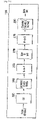
- FIGURE 4 illustrates a flow diagram for messages between a base station and a user equipment according to embodiments of the present disclosure.
- the embodiment of the flow diagram shown in FIGURE 4 is for illustration only. Other embodiments of the flow diagram could be used without departing from the scope of this disclosure.
- BS 102 schedules and initiates a DL transmission to UE 116. For each sub-frame 310-319 in the DL transmission, BS 102 sends DL Control Information (DCI) to UE 116 in the PDCCH.
- DCI DL Control Information
- the DCI is located within the first few OFDM symbols in the sub-frame 310-319.
- the DCI can be located in one or more of sub-frames 310, 311 and 312.
- the DCI can be located in one of the symbols, used as the DL carrier 330, in the time slot 320, 325 (as illustrated in FIGURE 3 ).
- the DCI indicates the allocated RBs for UE 116 as well as additional information.
- UE 116 Upon reception of the DL grant targeted to UE 116, UE 116 attempts to decode the transmitted message regarding the allocated RBs. Depending upon the decoding results for each transmitted sub-frame 310-319, UE 116 sends hybrid-ARQ bits (or uplink ACK/NACK bits) to BS 102 a few sub-frames later. For example, in a Frequency-Division Duplex (FDD) system, UE 116 transmits the ACK/NACK response 405 in sub-frame n in response to the decoding result for the DCI 410 received in sub-frame n - 4.
- FDD Frequency-Division Duplex
- FIGURE 5 illustrates Channel Control Element (CCE) resources in a DL carrier.
- CCE Channel Control Element
- a PDCCH that carries DCI is transmitted on an aggregation of one or several consecutive CCEs 500.
- the CCEs 500 available in the DL carrier 330 are numbered from 0 to N CCE -1.
- the CCEs 500 are control elements used for sending downlink grant.
- UE 116 reads the CCEs 500 to determine the downlink grant allocated to UE 116. For example, if CCE '012' is sent to UE 116, UE 116 determines that CCE '012' are allocated to UE 116. Therefore, UE 116 not only looks at the content of the CCE but also the location where the content is sent. Therefore, in some embodiments, UE 116 knows which resources to use to respond (e.g., ACK/NACK) based on what CCEs are used for the downlink grant.
- resources to use to respond e.g., ACK/NACK
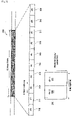
- FIGURE 6 illustrates an LTE Physical Uplink Control Channel (PUCCH) resource partition in on RB in the Uplink (UL) carrier.
- PUCCH Physical Uplink Control Channel
- the embodiment of the PUCCH partition 600 shown in FIGURE 6 is for illustration only. Other embodiments of the CCEs could be used without departing from the scope of this disclosure.
- UL ACK/NACK (AN) bits are transmitted on PUCCH formats 1a and 1b.
- Resources used for transmission of PUCCH format 1a/1b are represented by the non-negative index n PUCCH 1 .
- PUCCH resource index n PUCCH 1 for hybrid automatic repeat request (HARQ) - ACK/NCAK determines an orthogonal cover 605 and a cyclic shift 610.
- the orthogonal cover 605 and cyclic shift 610 indicate a unique resource. For example, thirty six (e.g., 3x12) PUCCH AN resources are available in one RB.
- FIGURE 7 illustrates network 700 that is capable of decoding data streams according to embodiments of the present disclosure.
- the embodiment of the network 700 shown in FIGURE 7 is for illustration only. Other embodiments could be used without departing from the scope of this disclosure.
- user equipments (UEs) 713 and 714 are connected to the base stations (BS) 701 having the cell ID of N ID , 1 cell , through to local base station 701a and 701b.
- User equipment 711 is directly connected to BS 701.
- UEs 712 and 715 are connected to BS 702 having the cell ID of N ID , 2 cell .
- UEs 713 and 714 connected to BS 701 are located far from each other.
- UEs 712 and 715 connected to different BS 702 are also far from each other.
- UEs 711 and 712 are closely located but connected to two different base stations, that is, UE 711 is connected to BS 701 and SS 712 is connected to BS 702.
- the user equipment that are closely located to interfere with another user equipment above a specified threshold, and connected to different cell from another user equipment respectively is denoted as 'high interfering user equipment' for this disclosure.
- UEs 711 and 712 illustrated in FIGURE 7 are the high interfering user equipments.
- the specified threshold can be adjusted in various levels to meet the service provider's requirements.
- the network 700 can transmit to the user equipments both a cell specific radio resource control (RRC) configuration and an UE specific RRC configuration.
- the cell specific RRC configuration can include a cell specific resource offset parameter for the PUCCH HARQ-ACK.
- the UE specific configuration can include a UE specific RS base sequence parameter and a UE specific resource offset parameter for the PUCCH HARQ-ACK.
- the user equipment can transmit an UE specific PUCCH carrying HARQ-ACK, which is generated with an UE specific RS generated using UE specific RS base sequence parameter and an UE specific resource offset parameter for the PUCCH HARQ-ACK.
- the user equipment can transmit a cell specific PUCCH carrying an HARQ-ACK, which is generated with the cell specific reference signal generated using the cell specific resource offset parameter for a PUCCH HARQ-ACK.
- the network 700 can transmit the identical UE specific RS base sequence and UE specific resource offset parameters to the UEs 711 and 712 whose interference are higher than the specified threshold.
- the high interfering UEs 711 and 712 can transmit the coordinated PUCCH carrying HARQ-ACK information, which is generated using the identical UE specific RRC configuration.
- the network 700 can transmit UE specific RRC configuration to the UEs such as UE 713, 714 and 715 whose interferences are lower than the specified threshold.
- the low interfering UEs can transmit the UE specific PUCCHs carrying HARQ-ACK information, which are generated based the UE specific RRC configurations.
- the network 700 can transmit the identical UE specific RS configuration base sequence parameter to the UEs 711 and 712.
- UEs 711 and 712 transmit the PUCCH carrying HARQ-ACK, using the same RS base sequence 1.
- UEs 711 and 712 cause a small UL interference to each other.
- UEs 713, 714 and 715 transmit the UE specific PUCCH generated with the UE specific RS base sequences, which are RS base sequence 2, 3, and 4 respectively.
- the PUCCHs transmitted from the user equipments can be orthogonal each other.
- the threshold to determine high interference or low interference can be adjusted to meet the service provider's various requirements.
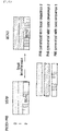
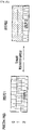
- FIGURES 8A and 8B illustrate PUCCH physical resource blocks that are designated to the interfering user equipments according to embodiments of the present disclosure.
- the embodiments of the PUCCH physical resource blocks shown in FIGURES 8A and 8B are for illustration only. Other embodiments could be used without departing from the scope of this disclosure.
- UEs 711 and 712 transmit the coordinated PUCCH carrying HARQ-ACK, using the same RS base sequence 1. Thus, UEs 711 and 712 can reduce UL interference each other.
- n CCE is a number of the smallest channel control element (CCE) used for transmission of a corresponding downlink control information scheduling a PDSCH for which the PUCCH carries the HARQ-ACK information
- N PUCCH 1 is the UE specific resource offset parameter in case the UE specific RRC configuration is applicable to the user equipment; otherwise N PUCCH 1 is the cell specific resource offset parameter.
- the UE specific RRC configuration can contain an indication parameter indicating whether the UE specific RRC configuration or the cell specific RRC configuration is applicable to the user equipment.
- the indication parameter can have a value of TRUE or FALSE, wherein TRUE means that the UE specific RRC configuration is applicable to the user equipment and FALSE means that the cell specific RRC configuration is applicable to the user equipment.
- N PUCCH 1 can be derived from at least one of the CSI-RS configuration numbers associated with non-zero CSI-RS transmission power defined in Table 6.10.5.2-1 in 3GPP TS 36.211, version 10.1.0, "E-UTRA, Physical Channels And Modulation", the contents of which are hereby incorporated by reference and which is denoted as NCSI-RS for this disclosure as follows:
- the network can semi-statically configure a set of N candidates for N PUCCH 1 by RRC configuration, the network dynamically indicates one N PUCCH 1 out of the N candidates by dynamic signaling.
- the number of the N candidates can be four and a two-bit information element (IE) is included in the PDCCH, e.g., corresponding to the downlink grant to generate four (4) candidate n PUCCH 1 s .
- n PUCCH 1 can be selected among four (4) candidate n PUCCH 1 s, depending on the value of IE as followed in exemplary TABLE 1.
- TABLE - 1 The two-bit IE indicating n PUCCH 1 Indicated n PUCCH 1 value 00 The first n PUCCH 1 value configured by RRC 01 The second n PUCCH 1 value configured by RRC 10 The third n PUCCH 1 value configured by RRC 11 The fourth n PUCCH 1 value configured by RRC
- the number of the candidates N can be two and a one-bit information element (IE) is included in the PDCCH, e.g., corresponding to the downlink grant to generate two (2) candidate n PUCCH 1 s .
- IE information element
- One n PUCCH 1 can be selected from two (2) candidate n PUCCH 1 s , depending on the value of IE as followed in exemplary TABLE 2.
- TABLE - 2 The 1-bit IE indicating n PUCCH 1 Indicated n PUCCH 1 value 0 The first n PUCCH 1 value configured by RRC 1 The second n PUCCH 1 value configured by RRC
- n CCE is the number of the smallest channel control element (CCE) used for transmission of a corresponding downlink control information scheduling a PDSCH for which the PUCCH carries the HARQ-ACK information
- N PUCCH ,offset 1 is the UE specific resource offset parameter in case the UE specific RRC configuration is applicable to the user equipment; otherwise N PUCCH ,offset 1 is the cell specific resource offset parameter.
- N PUCCH ,offset 1 is derived from at least one of NCSI-RS as follows: NCSI-RS can be the CSI-RS configuration number of the primary base station from which the user equipment receives PDCCH; NCSI-RS can be the smallest CSI-RS configuration number out of all such CSI-RS configuration numbers; NCSI-RS can be the largest CSI-RS configuration number out of all such CSI-RS configuration numbers; or NCSI-RS can be the CSI-RS configuration number with the smallest subframeConfig-r10, an RRC parameter to configure CSI-RS subframe periodicity. Ties with more than one configuration numbers with the smallest subframe configuration, can be broken with either the smallest or the largest CSI-RS configuration number.
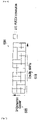
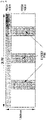
- FIGURE 9 illustrates downlink resource where enhanced PDCCHs (E-PDCCHs) are placed in the PDSCH regions.
- E-PDCCHs enhanced PDCCHs
- E-PDCCH 905 increases downlink (DL) control capacity within a base station and mitigates inter-cell interference for downlink control.
- a PUCCH format 1/1a/1b resource can be generated with reference signal (RS) base sequence that is depending on the location of DL grant, that is, whether PDCCH or E-PDCCH 905 is used for conveying a DL grant associated with the HARQ-ACK feedback.
- RS reference signal
- a user equipment generates user equipment-specific RS base sequence for a PUCCH format 1/1a/1b when the user equipment receives the corresponding downlink control information carried in in the E-PDCCH 905 region as shown in exemplary TABLE 3.
- Equation 1 or 2 can be used with n CCE being the first CCE number carrying the DL grant in the E-PDCCH 905 region.
- ⁇ gh ( n s ) is the group hopping pattern and ⁇ SS is sequence-shift pattern.
- ⁇ SS is equal to ⁇ ss PUCCH
- ⁇ SS is equal to ⁇ ss PUSCH
- the pseudo-random sequence c ( i ) is defined by section 7.2 in 3GPP TS No. 36.211, version 10.1.0, "E-UTRA, Physical Channels And Modulation", the contents of which are hereby incorporated by reference in their entirety.
- the parameter sequence-hopping-enabled provided by RRC determines whether sequence hopping is enabled or not. Sequence hopping for PUSCH can be disabled for a certain user equipment through the higher-layer parameter Disable-sequence-group-hopping despite being enabled on a cell basis.
- Equation 6 where ⁇ ss PUSCH is sequence-shift pattern for PUSCH and c init,SGH is the random seed for sequence group hopping (SGH).
- the random seed for sequence group hopping (SGH) c init can be configured such that the interfering user equipments are assigned to same uplink (UL) reference signal (RS) base sequence.
- sequence group hopping SGH
- N is the UE specific RS base sequence parameter in case the UE specific RRC configuration is applicable to the user equipment; otherwise N is the cell identification of the cell. N can be replaced with the sum of N ID cell and N UEoffset PUCCH which is configured by RRC configuration.
- PUSCH physical uplink shared channel
- DM RS demodulation reference signal
- ⁇ ss PUCCH is sequence-shift pattern for PUCCH and ⁇ ss ′ is configured by RRC configuration.
- ⁇ ss ′ can be set to be ⁇ SS as defined in 3GPP TS 36.211 version 8.9.0. which is hereby incorporated into the present disclosure as if fully set forth herein, and N UEoffset PUCCH can be configured by RRC such as RRC or by dynamic signaling such that the interfering user equipments are assigned to same uplink (UL) reference signal (RS) base sequence.
- RRC such as RRC
- RS reference signal
- N UEoffset PUCCH can be zero and ⁇ ss ′ can be user equipment-specifically configured by RRC such as RRC or dynamic signaling such that the high interfering user equipments are assigned to same uplink (UL) reference signal (RS) base sequence. Consequently, the sequence-shift patterns of PUCCH, PUSCH DM RS and SRS can be user equipment-specifically configured for the user equipments.
- RRC such as RRC
- RS reference signal
- both ⁇ ss ′ and N UEoffset PUCCH can be configured by UE specific RRC configuration or dynamic signaling such that the high interfering user equipments are assigned to the same uplink (UL) reference signal (RS) base sequence parameter.
- UL uplink
- RS reference signal
- N UEoffset PUCCH value can be configured from ⁇ 0,1,...,29 ⁇ by RRC or dynamic signaling such that the interfering user equipments are assigned to same uplink (UL) reference signal (RS) base sequence.
- UL uplink
- RS reference signal
- ⁇ ss ′ value can be configured from ⁇ 0,1,...,29 ⁇ by RRC or dynamic signaling such that the interfering user equipments are assigned to same uplink (UL) reference signal (RS) base sequence.
- UL uplink
- RS reference signal
- ⁇ ss ′ can be dynamically signaled in an uplink (UL) grant, e.g., downlink control indication (DCI) format 0 or DCI format 4.
- DCI downlink control indication
- the dynamic signaling selects one ⁇ ss ′ value out of N candidate ⁇ ss ′ values such that the high interfering user equipments are assigned to same uplink (UL) reference signal (RS) base sequence.
- UL uplink
- RS reference signal
- ⁇ ss ′ value is configured by RRC from ⁇ 0,1,...,29 ⁇ such that the high interfering user equipments are assigned to same uplink (UL) reference signal (RS) base sequence.
- UL uplink
- RS reference signal
- the network can semi-statically configure a set of N candidates for ⁇ ss ′ by RRC configuration, the network dynamically select one ⁇ ss ′ out of the N candidates by PDCCH signaling such that the high interfering user equipments are assigned to same uplink (UL) reference signal (RS) base sequence.
- UL uplink
- RS reference signal
- the number of the candidates N can be four and a two-bit information element (IE) can be included in the uplink (UL) grant as set in the following exemplary TABLE 4.
- IE information element
- TABLE - 4 The two-bit IE indicating ⁇ ss ′ Indicated ⁇ ss ′ value 00
- the first ⁇ ss ′ value configured by RRC 01 The second ⁇ SS ′ value configured by RRC 10
- the third ⁇ SS ′ value configured by RRC 11
- the fourth ⁇ SS ′ value configured by RRC
- the number of the candidates N can be two, and a one-bit information element (IE) can be included in the UL grant as set in the following exemplary TABLE 5.
- IE information element
- TABLE - 5 The one-bit IE indicating ⁇ SS ′ Indicated ⁇ SS ′ value 0
- N UEoffset PUCCH is signaled in a transmission grant, which can be either downlink (DL) grant or uplink (UL) grant such that the high interfering user equipments are assigned to same uplink (UL) reference signal (RS) base sequence.
- a transmission grant which can be either downlink (DL) grant or uplink (UL) grant such that the high interfering user equipments are assigned to same uplink (UL) reference signal (RS) base sequence.
- the N candidate N UEoffset PUCCH values are configured by a high layer such as RRC or dynamic signaling.
- N candidate N UEoffset PUCCH s values has a group of ⁇ 0,1,...,29 ⁇ , or the N candidate N UEoffse PUCCH can be indicated as ⁇ ss ′ is indicated in TABLE 4 or TABLE 5.
- PUCCH physical uplink control channel
- SRS sounding reference signal
- f ss PUCCH N ID cell + N UEoffset PUCCH mod 30 and physical uplink shared channel (PUSCH) demodulation reference signal (DM RS)
- f ss PUSCH f ss PUCCH +
- At least one of the sequence-shift patterns ⁇ ss PUCCH and ⁇ ss PUSCH can be configured by RRC or by dynamic signaling, where ⁇ ss PUCCH or ⁇ ss PUSCH can be configured from ⁇ 0,1,...,29 ⁇ such that the high interfering user equipments are assigned to same uplink (UL) reference signal (RS) base sequence.
- UL uplink
- RS reference signal
- the network can semi-statically configure a set of N candidates for ⁇ ss PUSCH by RRC configuration and the network dynamically select one f ss PUSCH out of the N candidates by PDCCH signaling such that the high interfering user equipments are assigned to same UL RS base sequence.
- the number of the candidates N can be four and a two-bit information element (IE) can be included in the uplink (UL) grant as set in the following TABLE 8: TABLE - 8
- the two-bit IE indicating f ss PUSCH Indicated f ss PUSCH value 00
- the third f ss PUSCH value configured by RRC 11 The fourth f ss PUSCH value configured by RRC
- the number of the candidates N can be two, and a one-bit information element (IE) is included in the UL grant as set in the following TABLE 9.
- IE information element
- TABLE - 9 The one-bit IE indicating f ss PUSCH Indicated f ss PUSCH value 0
- ⁇ ss PUCCH can be signaled in a transmission grant, which can be either downlink (DL) grant or uplink (UL) grant configured such that the high interfering user equipments are assigned to same uplink (UL) reference signal (RS) base sequence.
- the N candidate ⁇ ss PUCCH values can be configured by a high layer such as RRC or dynamic signaling.
- N candidate ⁇ ss PUCCH s values has a group of ⁇ 0,1,...,29 ⁇ , or the N candidate ⁇ ss PUCCH can be indicated as ⁇ ss PUSCH indicated in TABLE 8 or TABLE 9.
- the PUCCH decoding performance is improved. That is, the decoding failure probability with the same transmission power is decreased.
- the performance gain thanks to the UE specific RS base sequence configuration mainly comes from the following aspects: Reduced PUCCH interference as now the two PUCCH signals are orthogonally multiplexed and Cooperation gain in case of UL Cooperative Multi-Point (CoMP) reception in which case two cells cooperative to decode the PUCCHs generated with same RS base sequence.
- CoMP Coordinat Multipoint
- uplink cell splitting gain can be increased by assigning UE specific RRC configuration.
- coordinated multipoint (CoMP) transmission points refer to transmitters associated with a CoMP transmission to a user equipment (UE) in a subframe.
- TPs can include remote radio heads (RRHs), macro eNodeBs, femto eNodeBs, pico eNodeBs, base stations, and the like.
- RRHs remote radio heads
- CoMP TPs can have different cell IDs.
- CoMP TPs can share the same cell IDs.
- Coordinated multipoint (CoMP) reception points (RPs) refer to receivers associated with a CoMP transmission from a user equipment (UE) in a subframe.
- RPs can include remote radio heads (RRHs), macro eNodeBs, femto eNodeBs, pico eNodeBs, base stations, and the like.
- RRHs remote radio heads
- CoMP RPs can have different cell IDs. In other embodiments, CoMP RPs can share the same cell IDs.
Landscapes
- Engineering & Computer Science (AREA)
- Signal Processing (AREA)
- Computer Networks & Wireless Communication (AREA)
- Mobile Radio Communication Systems (AREA)
Applications Claiming Priority (4)
| Application Number | Priority Date | Filing Date | Title |
|---|---|---|---|
| US201161498989P | 2011-06-20 | 2011-06-20 | |
| US13/525,095 US8718003B2 (en) | 2011-06-20 | 2012-06-15 | System and method for an uplink control signal in wireless communication systems |
| EP12803140.8A EP2721794B1 (en) | 2011-06-20 | 2012-06-20 | System and method for an uplink control signal in wireless communication systems |
| PCT/KR2012/004873 WO2012177046A2 (en) | 2011-06-20 | 2012-06-20 | System and method for an uplink control signal in wireless communication systems |
Related Parent Applications (1)
| Application Number | Title | Priority Date | Filing Date |
|---|---|---|---|
| EP12803140.8A Division EP2721794B1 (en) | 2011-06-20 | 2012-06-20 | System and method for an uplink control signal in wireless communication systems |
Publications (1)
| Publication Number | Publication Date |
|---|---|
| EP3998729A1 true EP3998729A1 (en) | 2022-05-18 |
Family
ID=47353605
Family Applications (2)
| Application Number | Title | Priority Date | Filing Date |
|---|---|---|---|
| EP21197982.8A Pending EP3998729A1 (en) | 2011-06-20 | 2012-06-20 | System and method for an uplink control signal in wireless communication systems |
| EP12803140.8A Active EP2721794B1 (en) | 2011-06-20 | 2012-06-20 | System and method for an uplink control signal in wireless communication systems |
Family Applications After (1)
| Application Number | Title | Priority Date | Filing Date |
|---|---|---|---|
| EP12803140.8A Active EP2721794B1 (en) | 2011-06-20 | 2012-06-20 | System and method for an uplink control signal in wireless communication systems |
Country Status (9)
| Country | Link |
|---|---|
| US (3) | US8718003B2 (enExample) |
| EP (2) | EP3998729A1 (enExample) |
| JP (2) | JP6026523B2 (enExample) |
| KR (2) | KR102033020B1 (enExample) |
| CN (2) | CN103688504B (enExample) |
| AU (1) | AU2012274241B2 (enExample) |
| RU (1) | RU2597006C2 (enExample) |
| WO (1) | WO2012177046A2 (enExample) |
| ZA (1) | ZA201309025B (enExample) |
Families Citing this family (50)
| Publication number | Priority date | Publication date | Assignee | Title |
|---|---|---|---|---|
| WO2011052949A2 (ko) | 2009-10-26 | 2011-05-05 | 엘지전자 주식회사 | 무선 통신 시스템에서 수신 확인 전송 방법 및 장치 |
| US8718003B2 (en) * | 2011-06-20 | 2014-05-06 | Samsung Electronics Co., Ltd. | System and method for an uplink control signal in wireless communication systems |
| US9246656B2 (en) * | 2011-06-24 | 2016-01-26 | Lg Electronics Inc. | Method for transmitting uplink control information, user equipment, method for receiving uplink control information, and base station |
| WO2013002583A2 (ko) * | 2011-06-28 | 2013-01-03 | 엘지전자 주식회사 | 무선통신 시스템에서 수신확인 전송 방법 및 장치 |
| WO2013002726A1 (en) * | 2011-06-30 | 2013-01-03 | Telefonaktiebolaget Lm Ericsson (Publ) | Method and device for handling base sequences in a communications network |
| JP2013017016A (ja) * | 2011-07-04 | 2013-01-24 | Sharp Corp | 基地局装置、移動局装置、通信システムおよび通信方法 |
| JP5895388B2 (ja) * | 2011-07-22 | 2016-03-30 | シャープ株式会社 | 端末装置、基地局装置、集積回路および通信方法 |
| JP5811443B2 (ja) * | 2011-07-22 | 2015-11-11 | シャープ株式会社 | 端末装置、基地局装置、集積回路および通信方法 |
| US9794955B2 (en) * | 2011-08-15 | 2017-10-17 | Texas Instruments Incorporated | Configuration of CSI-RS for CoMP feedback |
| CN106658732B (zh) * | 2011-08-15 | 2020-04-14 | 华为技术有限公司 | 控制信道资源的分配方法及装置 |
| WO2013032202A2 (ko) * | 2011-08-26 | 2013-03-07 | 엘지전자 주식회사 | 하향링크 신호 수신 방법 및 사용자기기와, 하향링크 신호 전송 방법 및 기지국 |
| WO2013048114A2 (en) * | 2011-09-26 | 2013-04-04 | Lg Electronics Inc. | Method and apparatus for transmitting and receiving uplink control information in radio access system |
| JP6027988B2 (ja) * | 2012-01-25 | 2016-11-16 | パナソニック インテレクチュアル プロパティ コーポレーション オブ アメリカPanasonic Intellectual Property Corporation of America | 端末、基地局、送信方法及び受信方法 |
| KR20140142701A (ko) | 2012-03-24 | 2014-12-12 | 엘지전자 주식회사 | 무선 통신 시스템에서 참조신호 송수신 방법 및 장치 |
| US9419764B2 (en) | 2012-05-11 | 2016-08-16 | Sun Patent Trust | Terminal device and transmission method |
| WO2014109797A1 (en) | 2013-01-14 | 2014-07-17 | Intel IP Corporation | Energy-harvesting devices in wireless networks |
| US10624075B2 (en) * | 2013-03-16 | 2020-04-14 | Qualcomm Incorporated | Apparatus and method for scheduling delayed ACKs/NACKs in LTE cellular systems |
| JP6161377B2 (ja) * | 2013-04-12 | 2017-07-12 | 株式会社Nttドコモ | 無線基地局、ユーザ端末及び無線通信方法 |
| US9706568B2 (en) * | 2013-06-28 | 2017-07-11 | Texas Instruments Incorporated | Uplink control signaling for joint FDD and TDD carrier aggregation |
| CN105493596B (zh) * | 2013-09-26 | 2019-01-15 | 夏普株式会社 | 终端、基站以及通信方法 |
| KR102199693B1 (ko) | 2013-11-01 | 2021-01-07 | 후아웨이 테크놀러지 컴퍼니 리미티드 | 무선 통신 시스템에서 셀 간 간섭을 제거하는 장치 및 방법 |
| US9641310B2 (en) * | 2013-12-13 | 2017-05-02 | Qualcomm Incorporated | Network assisted interference cancellation signaling |
| CN104767595A (zh) * | 2014-01-07 | 2015-07-08 | 中兴通讯股份有限公司 | Harq-ack反馈信息的传输方法、系统及终端和基站 |
| WO2015137747A1 (ko) * | 2014-03-12 | 2015-09-17 | 엘지전자 주식회사 | 무선 자원의 용도 변경을 지원하는 무선 통신 시스템에서 상향링크 제어 채널 송신 방법 및 이를 위한 장치 |
| WO2015197110A1 (en) * | 2014-06-24 | 2015-12-30 | Huawei Technologies Co., Ltd. | Method and apparatus for multiple access in a wireless communication system |
| KR20220145420A (ko) | 2014-08-15 | 2022-10-28 | 인터디지탈 패튼 홀딩스, 인크 | 감소된 대역폭을 갖는 wtru에 대한 업링크 송신 및 mbms를 지원하기 위한 방법 및 장치 |
| US9629066B2 (en) * | 2015-02-24 | 2017-04-18 | Huawei Technologies Co., Ltd. | System and method for transmission time intervals |
| CN107211443B (zh) * | 2015-02-26 | 2021-01-22 | 苹果公司 | 用于无线电接入技术协调的系统、方法及设备 |
| CN106059726B (zh) * | 2015-04-17 | 2019-06-25 | 中国移动通信集团公司 | 一种上行控制信道资源确定方法及装置 |
| US11026142B2 (en) | 2016-01-20 | 2021-06-01 | Qualcomm Incorporated | Techniques for providing uplink-based mobility |
| CN109314617B (zh) * | 2016-06-30 | 2023-03-03 | 苹果公司 | 用于5g dci解码中的crc模糊避免的方法 |
| US10541785B2 (en) | 2016-07-18 | 2020-01-21 | Samsung Electronics Co., Ltd. | Carrier aggregation with variable transmission durations |
| WO2018142264A1 (en) * | 2017-02-01 | 2018-08-09 | Telefonaktiebolaget Lm Ericsson (Publ) | Methods and nodes for activation or deactivation of a carrier in a communication network supporting carrier aggregation |
| US11483810B2 (en) | 2017-04-03 | 2022-10-25 | Huawei Technologies Co., Ltd. | Methods and systems for resource configuration of wireless communication systems |
| US10798704B2 (en) * | 2017-04-28 | 2020-10-06 | Qualcomm Incorporated | Reference signal design for slot aggregation |
| MX2019012984A (es) | 2017-05-05 | 2020-01-13 | Ericsson Telefon Ab L M | Asignacion de recursos de acuse de recibo. |
| KR102662410B1 (ko) | 2017-08-11 | 2024-05-03 | 주식회사 윌러스표준기술연구소 | 무선 통신 시스템에서 상향링크 제어채널의 송수신 방법, 장치, 및 시스템 |
| US11166274B2 (en) * | 2017-08-24 | 2021-11-02 | Qualcomm Incorporated | User equipment-specific hybrid automatic repeat request timeline offset |
| US10644765B2 (en) * | 2017-10-24 | 2020-05-05 | Intel Corporation | Enhanced acknowledgment and power saving for wireless communications |
| CN109802811B (zh) * | 2017-11-17 | 2021-05-18 | 北京紫光展锐通信技术有限公司 | 物理层上行控制信道pucch资源的配置方法及用户终端 |
| CN109818895B (zh) * | 2017-11-17 | 2022-04-29 | 中兴通讯股份有限公司 | 确定序列组的方法及装置,确定循环移位的方法及装置 |
| US11303384B2 (en) * | 2017-11-29 | 2022-04-12 | Qualcomm Incorporated | User equipment shift randomization for uplink control channel transmission |
| CN116827485A (zh) | 2018-01-05 | 2023-09-29 | 日本电气株式会社 | 用于无线通信系统中的上行链路信号传输和接收的方法和设备 |
| CN108401508B (zh) * | 2018-01-31 | 2022-01-18 | 北京小米移动软件有限公司 | 配置参数发送、读取方法及装置、基站和用户设备 |
| US11051331B2 (en) * | 2018-05-11 | 2021-06-29 | Qualcomm Incorporated | Techniques and apparatuses for paired physical downlink shared channel and physical uplink shared channel scheduling |
| PL3836442T3 (pl) * | 2018-08-08 | 2024-05-06 | Beijing Xiaomi Mobile Software Co., Ltd. | Sposób i urządzenie do zwracania hybrydowego, automatycznego powtarzania żądań (HARQ) |
| US12120060B2 (en) * | 2018-09-19 | 2024-10-15 | Qualcomm Incorporated | Acknowledgement codebook design for multiple transmission reception points |
| CN110932820B (zh) | 2018-09-19 | 2022-01-14 | 华为技术有限公司 | 发送和接收上行控制信息的方法以及通信装置 |
| WO2020155189A1 (zh) * | 2019-02-03 | 2020-08-06 | 华为技术有限公司 | 参考信号接收与发送方法、装置及系统 |
| CN114826524B (zh) * | 2019-08-16 | 2024-03-29 | 华为技术有限公司 | 混合自动重传请求确认harq-ack资源确定方法 |
Family Cites Families (33)
| Publication number | Priority date | Publication date | Assignee | Title |
|---|---|---|---|---|
| US2A (en) * | 1826-12-15 | 1836-07-29 | John Goulding | Mode of manufacturing wool or other fibrous materials |
| KR100735225B1 (ko) * | 2003-07-12 | 2007-07-03 | 삼성전자주식회사 | 이동통신 시스템에서 보코더 자원 관리 방법 |
| KR101376233B1 (ko) * | 2007-10-02 | 2014-03-21 | 삼성전자주식회사 | 주파수 분할 다중 접속 방식의 시스템에서 제어 채널의자원 할당 장치 및 방법 |
| CN103546255B (zh) * | 2007-10-29 | 2016-11-02 | 松下电器产业株式会社 | 集成电路 |
| CN101960736B (zh) * | 2008-02-28 | 2013-07-31 | Lg电子株式会社 | 复用数据及控制信息的方法 |
| US9036564B2 (en) * | 2008-03-28 | 2015-05-19 | Qualcomm Incorporated | Dynamic assignment of ACK resource in a wireless communication system |
| EP2269327B1 (en) * | 2008-04-21 | 2016-06-15 | LG Electronics Inc. | Method of transmitting control signal in wireless communication system |
| KR20090112534A (ko) * | 2008-04-23 | 2009-10-28 | 엘지전자 주식회사 | 상향링크 참조 신호 시퀀스 생성 방법 |
| KR101589600B1 (ko) * | 2008-08-05 | 2016-01-28 | 삼성전자주식회사 | 직교 주파수 분할 다중 접속 방식의 이동통신 시스템에서 하향링크 데이터 채널에 대한 상향링크 응답 채널 송수신 방법 및 장치 |
| KR101441147B1 (ko) * | 2008-08-12 | 2014-09-18 | 엘지전자 주식회사 | 무선 통신 시스템에서 sr 전송 방법 |
| KR101629298B1 (ko) * | 2008-10-30 | 2016-06-10 | 엘지전자 주식회사 | 무선 통신 시스템에서 제어 신호를 전송하는 방법 및 이를 위한 장치 |
| JP5538802B2 (ja) * | 2008-11-04 | 2014-07-02 | 三菱電機株式会社 | 通信方法、移動体通信システム、移動端末および基地局制御装置 |
| US8520621B2 (en) * | 2008-11-04 | 2013-08-27 | Apple Inc. | Providing a downlink control structure in a first carrier to indicate control information in a second, different carrier |
| EP2357735B1 (en) * | 2008-11-14 | 2016-11-09 | LG Electronics Inc. | Method and apparatus for information transmission in wireless communication system |
| CN102246553A (zh) * | 2008-12-15 | 2011-11-16 | 诺基亚公司 | 用于扩展的带宽系统的下行链路控制和物理混合arq指示符信道(phich)配置 |
| WO2010123893A1 (en) | 2009-04-22 | 2010-10-28 | Interdigital Patent Holdings, Inc. | Method and apparatus for transmitting uplink control information for carrier aggregated spectrums |
| CN101931961A (zh) * | 2009-06-23 | 2010-12-29 | 华为技术有限公司 | 实现中继系统回程链路控制信道传输的方法、系统和设备 |
| CN101616360B (zh) * | 2009-07-24 | 2012-05-09 | 中兴通讯股份有限公司 | 一种定位参考信号的发送方法及系统 |
| US20110205981A1 (en) * | 2009-08-13 | 2011-08-25 | Changsoo Koo | Multiplexing uplink l1/l2 control and data |
| US8467799B2 (en) | 2009-08-20 | 2013-06-18 | Samsung Electronics Co., Ltd. | Method and system for assigning physical uplink control channel (PUCCH) resources |
| TWI628933B (zh) * | 2009-10-01 | 2018-07-01 | 內數位專利控股公司 | 傳輸上鏈控制資訊的方法及系統 |
| EP2491671B1 (en) | 2009-10-19 | 2021-06-16 | Samsung Electronics Co., Ltd. | Transmission diversity and multiplexing for harq-ack signals in communication systems |
| CN101702644B (zh) * | 2009-11-02 | 2014-08-13 | 中兴通讯股份有限公司 | 一种物理混合重传指示信道的传输方法和装置 |
| US8576755B2 (en) * | 2010-01-11 | 2013-11-05 | Qualcomm Incorporated | Apparatus and method for relay transition time |
| EP2547017B1 (en) * | 2010-03-11 | 2018-08-29 | LG Electronics Inc. | Control channel allocation method, and apparatus for same |
| ES2588978T3 (es) * | 2010-04-02 | 2016-11-08 | Interdigital Patent Holdings, Inc. | Configuración y transmisión de señales de sondeo de referencia de enlace ascendente |
| WO2011137408A2 (en) * | 2010-04-30 | 2011-11-03 | Interdigital Patent Holdings, Inc. | Determination of carriers and multiplexing for uplink control information transmission |
| US9258092B2 (en) * | 2010-09-17 | 2016-02-09 | Blackberry Limited | Sounding reference signal transmission in carrier aggregation |
| CN103109488B (zh) * | 2010-09-19 | 2016-01-06 | Lg电子株式会社 | 用于发送控制信息的方法和装置 |
| CN104954111A (zh) * | 2010-10-01 | 2015-09-30 | 捷讯研究有限公司 | 正交资源选择发送分集和资源指派 |
| US8514826B2 (en) * | 2010-11-02 | 2013-08-20 | Lg Electronics Inc. | Method and apparatus for transmitting control information in radio communication system |
| US9413509B2 (en) * | 2011-06-17 | 2016-08-09 | Texas Instruments Incorporated | Hybrid automatic repeat request acknowledge resource allocation for enhanced physical downlink control channel |
| US8718003B2 (en) * | 2011-06-20 | 2014-05-06 | Samsung Electronics Co., Ltd. | System and method for an uplink control signal in wireless communication systems |
-
2012
- 2012-06-15 US US13/525,095 patent/US8718003B2/en active Active
- 2012-06-20 WO PCT/KR2012/004873 patent/WO2012177046A2/en not_active Ceased
- 2012-06-20 AU AU2012274241A patent/AU2012274241B2/en active Active
- 2012-06-20 EP EP21197982.8A patent/EP3998729A1/en active Pending
- 2012-06-20 RU RU2013156689/07A patent/RU2597006C2/ru active
- 2012-06-20 CN CN201280035786.XA patent/CN103688504B/zh active Active
- 2012-06-20 KR KR1020137033785A patent/KR102033020B1/ko active Active
- 2012-06-20 JP JP2014516913A patent/JP6026523B2/ja active Active
- 2012-06-20 EP EP12803140.8A patent/EP2721794B1/en active Active
- 2012-06-20 CN CN201710372802.9A patent/CN107257269B/zh active Active
- 2012-06-20 KR KR1020197029783A patent/KR102301970B1/ko active Active
-
2013
- 2013-12-02 ZA ZA2013/09025A patent/ZA201309025B/en unknown
-
2014
- 2014-03-28 US US14/229,235 patent/US8902786B2/en active Active
- 2014-12-02 US US14/558,286 patent/US9357538B2/en active Active
-
2016
- 2016-10-12 JP JP2016200720A patent/JP6328720B2/ja active Active
Non-Patent Citations (2)
| Title |
|---|
| "LTE; Evolved Universal Terrestrial Radio Access (E-UTRA); Physical channels and modulation (3GPP TS 36.211 version 10.2.0 Release 10)", TECHNICAL SPECIFICATION, EUROPEAN TELECOMMUNICATIONS STANDARDS INSTITUTE (ETSI), 650, ROUTE DES LUCIOLES ; F-06921 SOPHIA-ANTIPOLIS ; FRANCE, vol. 3GPP RAN 1, no. V10.2.0, 1 June 2011 (2011-06-01), XP014066382 * |
| 3GPP: "3rd Generation Partnership Project; Technical Specification Group Radio Access Network; Evolved Universal Terrestrial Radio Access (E-UTRA); Physical layer procedures (Release 10)", 3GPP DRAFT; DRAFT36213-A20, 3RD GENERATION PARTNERSHIP PROJECT (3GPP), MOBILE COMPETENCE CENTRE ; 650, ROUTE DES LUCIOLES ; F-06921 SOPHIA-ANTIPOLIS CEDEX ; FRANCE, vol. RAN WG1, 16 June 2011 (2011-06-16), XP050537179 * |
Also Published As
| Publication number | Publication date |
|---|---|
| EP2721794A4 (en) | 2016-03-02 |
| US20120320847A1 (en) | 2012-12-20 |
| US9357538B2 (en) | 2016-05-31 |
| AU2012274241A1 (en) | 2013-10-31 |
| KR20190118686A (ko) | 2019-10-18 |
| CN107257269B (zh) | 2020-06-30 |
| KR102033020B1 (ko) | 2019-11-08 |
| KR102301970B1 (ko) | 2021-09-15 |
| AU2012274241B2 (en) | 2016-07-07 |
| ZA201309025B (en) | 2015-06-24 |
| CN107257269A (zh) | 2017-10-17 |
| KR20140037133A (ko) | 2014-03-26 |
| US8718003B2 (en) | 2014-05-06 |
| WO2012177046A2 (en) | 2012-12-27 |
| US20150131582A1 (en) | 2015-05-14 |
| JP6026523B2 (ja) | 2016-11-16 |
| CN103688504B (zh) | 2017-06-20 |
| EP2721794A2 (en) | 2014-04-23 |
| US20140226581A1 (en) | 2014-08-14 |
| JP2014523677A (ja) | 2014-09-11 |
| JP6328720B2 (ja) | 2018-05-23 |
| RU2597006C2 (ru) | 2016-09-10 |
| US8902786B2 (en) | 2014-12-02 |
| EP2721794B1 (en) | 2021-09-22 |
| RU2013156689A (ru) | 2015-06-27 |
| WO2012177046A3 (en) | 2013-04-04 |
| JP2017063435A (ja) | 2017-03-30 |
| CN103688504A (zh) | 2014-03-26 |
Similar Documents
| Publication | Publication Date | Title |
|---|---|---|
| EP2721794B1 (en) | System and method for an uplink control signal in wireless communication systems | |
| US8565066B2 (en) | System and method for an uplink acknowledgement transmission in carrier-aggregated wireless communication systems | |
| US8305986B2 (en) | Method and apparatus for uplink transmissions and CQI reports with carrier aggregation | |
| USRE49548E1 (en) | High-order multiple-user multiple-input multiple-output operation for wireless communication systems | |
| JP5808791B2 (ja) | キャリア集合無線通信におけるアップリンク承認信号を伝送するための方法及びそのシステム | |
| US8805448B2 (en) | Method and system for indicating method used to scramble dedicated reference signals | |
| KR101776097B1 (ko) | 업링크 제어 정보를 매핑하기 위한 방법 및 시스템 | |
| US8755332B2 (en) | Radio communication control method, base station apparatus and mobile terminal apparatus | |
| US20100172308A1 (en) | System and method for downlink physical indicator channel mapping with asymmetric carrier aggregation | |
| US20130201926A1 (en) | System and method for physical downlink control and hybrid-arq indicator channels in lte-a systems | |
| US20110085503A1 (en) | Method and system of multi-layer beamforming | |
| US11063644B2 (en) | Method and apparatus for control signaling for multi-stream transmission | |
| JPWO2016158537A1 (ja) | 無線基地局、ユーザ端末及び無線通信方法 | |
| CN105281867B (zh) | 控制信息的传输方法及装置 |
Legal Events
| Date | Code | Title | Description |
|---|---|---|---|
| PUAI | Public reference made under article 153(3) epc to a published international application that has entered the european phase |
Free format text: ORIGINAL CODE: 0009012 |
|
| STAA | Information on the status of an ep patent application or granted ep patent |
Free format text: STATUS: THE APPLICATION HAS BEEN PUBLISHED |
|
| AC | Divisional application: reference to earlier application |
Ref document number: 2721794 Country of ref document: EP Kind code of ref document: P |
|
| AK | Designated contracting states |
Kind code of ref document: A1 Designated state(s): AL AT BE BG CH CY CZ DE DK EE ES FI FR GB GR HR HU IE IS IT LI LT LU LV MC MK MT NL NO PL PT RO RS SE SI SK SM TR |
|
| STAA | Information on the status of an ep patent application or granted ep patent |
Free format text: STATUS: REQUEST FOR EXAMINATION WAS MADE |
|
| 17P | Request for examination filed |
Effective date: 20220916 |
|
| RBV | Designated contracting states (corrected) |
Designated state(s): AL AT BE BG CH CY CZ DE DK EE ES FI FR GB GR HR HU IE IS IT LI LT LU LV MC MK MT NL NO PL PT RO RS SE SI SK SM TR |
|
| STAA | Information on the status of an ep patent application or granted ep patent |
Free format text: STATUS: EXAMINATION IS IN PROGRESS |
|
| 17Q | First examination report despatched |
Effective date: 20231219 |