EP3998436A1 - Water quantity adjustment device - Google Patents
Water quantity adjustment device Download PDFInfo
- Publication number
- EP3998436A1 EP3998436A1 EP20837122.9A EP20837122A EP3998436A1 EP 3998436 A1 EP3998436 A1 EP 3998436A1 EP 20837122 A EP20837122 A EP 20837122A EP 3998436 A1 EP3998436 A1 EP 3998436A1
- Authority
- EP
- European Patent Office
- Prior art keywords
- water
- refrigerant
- heat exchanger
- temperature sensor
- controller
- Prior art date
- Legal status (The legal status is an assumption and is not a legal conclusion. Google has not performed a legal analysis and makes no representation as to the accuracy of the status listed.)
- Granted
Links
Images

Classifications
-
- F—MECHANICAL ENGINEERING; LIGHTING; HEATING; WEAPONS; BLASTING
- F25—REFRIGERATION OR COOLING; COMBINED HEATING AND REFRIGERATION SYSTEMS; HEAT PUMP SYSTEMS; MANUFACTURE OR STORAGE OF ICE; LIQUEFACTION SOLIDIFICATION OF GASES
- F25B—REFRIGERATION MACHINES, PLANTS OR SYSTEMS; COMBINED HEATING AND REFRIGERATION SYSTEMS; HEAT PUMP SYSTEMS
- F25B41/00—Fluid-circulation arrangements
- F25B41/20—Disposition of valves, e.g. of on-off valves or flow control valves
-
- F—MECHANICAL ENGINEERING; LIGHTING; HEATING; WEAPONS; BLASTING
- F25—REFRIGERATION OR COOLING; COMBINED HEATING AND REFRIGERATION SYSTEMS; HEAT PUMP SYSTEMS; MANUFACTURE OR STORAGE OF ICE; LIQUEFACTION SOLIDIFICATION OF GASES
- F25B—REFRIGERATION MACHINES, PLANTS OR SYSTEMS; COMBINED HEATING AND REFRIGERATION SYSTEMS; HEAT PUMP SYSTEMS
- F25B49/00—Arrangement or mounting of control or safety devices
- F25B49/02—Arrangement or mounting of control or safety devices for compression type machines, plants or systems
-
- F—MECHANICAL ENGINEERING; LIGHTING; HEATING; WEAPONS; BLASTING
- F24—HEATING; RANGES; VENTILATING
- F24F—AIR-CONDITIONING; AIR-HUMIDIFICATION; VENTILATION; USE OF AIR CURRENTS FOR SCREENING
- F24F11/00—Control or safety arrangements
- F24F11/70—Control systems characterised by their outputs; Constructional details thereof
- F24F11/80—Control systems characterised by their outputs; Constructional details thereof for controlling the temperature of the supplied air
- F24F11/87—Control systems characterised by their outputs; Constructional details thereof for controlling the temperature of the supplied air by controlling absorption or discharge of heat in outdoor units
-
- F—MECHANICAL ENGINEERING; LIGHTING; HEATING; WEAPONS; BLASTING
- F24—HEATING; RANGES; VENTILATING
- F24F—AIR-CONDITIONING; AIR-HUMIDIFICATION; VENTILATION; USE OF AIR CURRENTS FOR SCREENING
- F24F11/00—Control or safety arrangements
- F24F11/70—Control systems characterised by their outputs; Constructional details thereof
- F24F11/80—Control systems characterised by their outputs; Constructional details thereof for controlling the temperature of the supplied air
- F24F11/83—Control systems characterised by their outputs; Constructional details thereof for controlling the temperature of the supplied air by controlling the supply of heat-exchange fluids to heat-exchangers
- F24F11/84—Control systems characterised by their outputs; Constructional details thereof for controlling the temperature of the supplied air by controlling the supply of heat-exchange fluids to heat-exchangers using valves
-
- F—MECHANICAL ENGINEERING; LIGHTING; HEATING; WEAPONS; BLASTING
- F24—HEATING; RANGES; VENTILATING
- F24F—AIR-CONDITIONING; AIR-HUMIDIFICATION; VENTILATION; USE OF AIR CURRENTS FOR SCREENING
- F24F3/00—Air-conditioning systems in which conditioned primary air is supplied from one or more central stations to distributing units in the rooms or spaces where it may receive secondary treatment; Apparatus specially designed for such systems
- F24F3/06—Air-conditioning systems in which conditioned primary air is supplied from one or more central stations to distributing units in the rooms or spaces where it may receive secondary treatment; Apparatus specially designed for such systems characterised by the arrangements for the supply of heat-exchange fluid for the subsequent treatment of primary air in the room units
- F24F3/065—Air-conditioning systems in which conditioned primary air is supplied from one or more central stations to distributing units in the rooms or spaces where it may receive secondary treatment; Apparatus specially designed for such systems characterised by the arrangements for the supply of heat-exchange fluid for the subsequent treatment of primary air in the room units with a plurality of evaporators or condensers
-
- F—MECHANICAL ENGINEERING; LIGHTING; HEATING; WEAPONS; BLASTING
- F24—HEATING; RANGES; VENTILATING
- F24F—AIR-CONDITIONING; AIR-HUMIDIFICATION; VENTILATION; USE OF AIR CURRENTS FOR SCREENING
- F24F5/00—Air-conditioning systems or apparatus not covered by F24F1/00 or F24F3/00, e.g. using solar heat or combined with household units such as an oven or water heater
- F24F5/0007—Air-conditioning systems or apparatus not covered by F24F1/00 or F24F3/00, e.g. using solar heat or combined with household units such as an oven or water heater cooling apparatus specially adapted for use in air-conditioning
- F24F5/0017—Air-conditioning systems or apparatus not covered by F24F1/00 or F24F3/00, e.g. using solar heat or combined with household units such as an oven or water heater cooling apparatus specially adapted for use in air-conditioning using cold storage bodies, e.g. ice
-
- F—MECHANICAL ENGINEERING; LIGHTING; HEATING; WEAPONS; BLASTING
- F24—HEATING; RANGES; VENTILATING
- F24D—DOMESTIC- OR SPACE-HEATING SYSTEMS, e.g. CENTRAL HEATING SYSTEMS; DOMESTIC HOT-WATER SUPPLY SYSTEMS; ELEMENTS OR COMPONENTS THEREFOR
- F24D19/00—Details
- F24D19/10—Arrangement or mounting of control or safety devices
- F24D19/1006—Arrangement or mounting of control or safety devices for water heating systems
- F24D19/1009—Arrangement or mounting of control or safety devices for water heating systems for central heating
- F24D19/1039—Arrangement or mounting of control or safety devices for water heating systems for central heating the system uses a heat pump
-
- F—MECHANICAL ENGINEERING; LIGHTING; HEATING; WEAPONS; BLASTING
- F24—HEATING; RANGES; VENTILATING
- F24F—AIR-CONDITIONING; AIR-HUMIDIFICATION; VENTILATION; USE OF AIR CURRENTS FOR SCREENING
- F24F5/00—Air-conditioning systems or apparatus not covered by F24F1/00 or F24F3/00, e.g. using solar heat or combined with household units such as an oven or water heater
- F24F5/0007—Air-conditioning systems or apparatus not covered by F24F1/00 or F24F3/00, e.g. using solar heat or combined with household units such as an oven or water heater cooling apparatus specially adapted for use in air-conditioning
- F24F5/0017—Air-conditioning systems or apparatus not covered by F24F1/00 or F24F3/00, e.g. using solar heat or combined with household units such as an oven or water heater cooling apparatus specially adapted for use in air-conditioning using cold storage bodies, e.g. ice
- F24F2005/0025—Air-conditioning systems or apparatus not covered by F24F1/00 or F24F3/00, e.g. using solar heat or combined with household units such as an oven or water heater cooling apparatus specially adapted for use in air-conditioning using cold storage bodies, e.g. ice using heat exchange fluid storage tanks
-
- F—MECHANICAL ENGINEERING; LIGHTING; HEATING; WEAPONS; BLASTING
- F24—HEATING; RANGES; VENTILATING
- F24F—AIR-CONDITIONING; AIR-HUMIDIFICATION; VENTILATION; USE OF AIR CURRENTS FOR SCREENING
- F24F2140/00—Control inputs relating to system states
- F24F2140/20—Heat-exchange fluid temperature
-
- F—MECHANICAL ENGINEERING; LIGHTING; HEATING; WEAPONS; BLASTING
- F25—REFRIGERATION OR COOLING; COMBINED HEATING AND REFRIGERATION SYSTEMS; HEAT PUMP SYSTEMS; MANUFACTURE OR STORAGE OF ICE; LIQUEFACTION SOLIDIFICATION OF GASES
- F25B—REFRIGERATION MACHINES, PLANTS OR SYSTEMS; COMBINED HEATING AND REFRIGERATION SYSTEMS; HEAT PUMP SYSTEMS
- F25B2313/00—Compression machines, plants or systems with reversible cycle not otherwise provided for
- F25B2313/004—Outdoor unit with water as a heat sink or heat source
-
- F—MECHANICAL ENGINEERING; LIGHTING; HEATING; WEAPONS; BLASTING
- F25—REFRIGERATION OR COOLING; COMBINED HEATING AND REFRIGERATION SYSTEMS; HEAT PUMP SYSTEMS; MANUFACTURE OR STORAGE OF ICE; LIQUEFACTION SOLIDIFICATION OF GASES
- F25B—REFRIGERATION MACHINES, PLANTS OR SYSTEMS; COMBINED HEATING AND REFRIGERATION SYSTEMS; HEAT PUMP SYSTEMS
- F25B2313/00—Compression machines, plants or systems with reversible cycle not otherwise provided for
- F25B2313/023—Compression machines, plants or systems with reversible cycle not otherwise provided for using multiple indoor units
- F25B2313/0233—Compression machines, plants or systems with reversible cycle not otherwise provided for using multiple indoor units in parallel arrangements
-
- F—MECHANICAL ENGINEERING; LIGHTING; HEATING; WEAPONS; BLASTING
- F25—REFRIGERATION OR COOLING; COMBINED HEATING AND REFRIGERATION SYSTEMS; HEAT PUMP SYSTEMS; MANUFACTURE OR STORAGE OF ICE; LIQUEFACTION SOLIDIFICATION OF GASES
- F25B—REFRIGERATION MACHINES, PLANTS OR SYSTEMS; COMBINED HEATING AND REFRIGERATION SYSTEMS; HEAT PUMP SYSTEMS
- F25B2339/00—Details of evaporators; Details of condensers
- F25B2339/04—Details of condensers
- F25B2339/047—Water-cooled condensers
-
- F—MECHANICAL ENGINEERING; LIGHTING; HEATING; WEAPONS; BLASTING
- F25—REFRIGERATION OR COOLING; COMBINED HEATING AND REFRIGERATION SYSTEMS; HEAT PUMP SYSTEMS; MANUFACTURE OR STORAGE OF ICE; LIQUEFACTION SOLIDIFICATION OF GASES
- F25B—REFRIGERATION MACHINES, PLANTS OR SYSTEMS; COMBINED HEATING AND REFRIGERATION SYSTEMS; HEAT PUMP SYSTEMS
- F25B2500/00—Problems to be solved
- F25B2500/19—Calculation of parameters
-
- F—MECHANICAL ENGINEERING; LIGHTING; HEATING; WEAPONS; BLASTING
- F25—REFRIGERATION OR COOLING; COMBINED HEATING AND REFRIGERATION SYSTEMS; HEAT PUMP SYSTEMS; MANUFACTURE OR STORAGE OF ICE; LIQUEFACTION SOLIDIFICATION OF GASES
- F25B—REFRIGERATION MACHINES, PLANTS OR SYSTEMS; COMBINED HEATING AND REFRIGERATION SYSTEMS; HEAT PUMP SYSTEMS
- F25B2600/00—Control issues
- F25B2600/25—Control of valves
- F25B2600/2515—Flow valves
-
- F—MECHANICAL ENGINEERING; LIGHTING; HEATING; WEAPONS; BLASTING
- F25—REFRIGERATION OR COOLING; COMBINED HEATING AND REFRIGERATION SYSTEMS; HEAT PUMP SYSTEMS; MANUFACTURE OR STORAGE OF ICE; LIQUEFACTION SOLIDIFICATION OF GASES
- F25B—REFRIGERATION MACHINES, PLANTS OR SYSTEMS; COMBINED HEATING AND REFRIGERATION SYSTEMS; HEAT PUMP SYSTEMS
- F25B2700/00—Sensing or detecting of parameters; Sensors therefor
- F25B2700/21—Temperatures
-
- F—MECHANICAL ENGINEERING; LIGHTING; HEATING; WEAPONS; BLASTING
- F25—REFRIGERATION OR COOLING; COMBINED HEATING AND REFRIGERATION SYSTEMS; HEAT PUMP SYSTEMS; MANUFACTURE OR STORAGE OF ICE; LIQUEFACTION SOLIDIFICATION OF GASES
- F25B—REFRIGERATION MACHINES, PLANTS OR SYSTEMS; COMBINED HEATING AND REFRIGERATION SYSTEMS; HEAT PUMP SYSTEMS
- F25B2700/00—Sensing or detecting of parameters; Sensors therefor
- F25B2700/21—Temperatures
- F25B2700/2103—Temperatures near a heat exchanger
-
- Y—GENERAL TAGGING OF NEW TECHNOLOGICAL DEVELOPMENTS; GENERAL TAGGING OF CROSS-SECTIONAL TECHNOLOGIES SPANNING OVER SEVERAL SECTIONS OF THE IPC; TECHNICAL SUBJECTS COVERED BY FORMER USPC CROSS-REFERENCE ART COLLECTIONS [XRACs] AND DIGESTS
- Y02—TECHNOLOGIES OR APPLICATIONS FOR MITIGATION OR ADAPTATION AGAINST CLIMATE CHANGE
- Y02B—CLIMATE CHANGE MITIGATION TECHNOLOGIES RELATED TO BUILDINGS, e.g. HOUSING, HOUSE APPLIANCES OR RELATED END-USER APPLICATIONS
- Y02B30/00—Energy efficient heating, ventilation or air conditioning [HVAC]
- Y02B30/70—Efficient control or regulation technologies, e.g. for control of refrigerant flow, motor or heating
Definitions
- Embodiments disclosed herein relate to a water regulator in a refrigeration cycle apparatus.
- Patent Literature 1 JP 2008-075948 A discloses an air conditioning apparatus of a water cooling type configured to regulate a flow rate of cooling water to be supplied, in order to optimize a high pressure at a refrigerant circuit.
- the present disclosure provides a controller capable of controlling a quantity of cooling water circulating in water pipes, without directly controlling a circulation pump.
- a first aspect provides a water regulator for controlling a quantity of water flowing through water pipes in a refrigeration cycle apparatus.
- the refrigeration cycle apparatus includes a refrigerant circuit through which a refrigerant flows, a circulation pump having a number of rotations controlled such that a difference between a pressure at an inlet of the circulation pump and a pressure at an outlet of the circulation pump falls within a predetermined range, the circulation pump being configured to circulate the water in the water pipes, and a heat exchanger configured to cause the refrigerant flowing through the refrigerant circuit to exchange heat with the water flowing through the water pipes.
- the water regulator includes: a water regulation valve configured to regulate the quantity of the water flowing through the water pipes; a first temperature sensor configured to measure a temperature of one of the water pipes which is connected to an inlet of the heat exchanger; a second temperature sensor configured to measure a temperature of one of the water pipes which is connected to an outlet of the heat exchanger; and a controller configured to control an opening degree of the water regulation valve, based on a difference between the temperature measured by the first temperature sensor and the temperature measured by the second temperature sensor.
- the water regulation valve of the water regulator controls the quantity of the water flowing through the water pipes.
- the water regulator therefore controls the quantity of the cooling water circulating in the water pipes, without directly controlling the circulation pump.
- a second aspect provides the water regulator according to the first aspect, in which the controller controls the opening degree of the water regulation valve such that the difference between the temperature measured by the first temperature sensor and the temperature measured by the second temperature sensor falls within a predetermined range.
- a third aspect provides the water regulator according to the first or second aspect, in which the controller adjusts the opening degree of the water regulation valve such that the quantity of the water flowing through the water pipes falls within a predetermined range.
- a fourth aspect provides the water regulator according to the third aspect, in which the controller calculates the quantity of the water, based on a refrigerant-side capacity of the refrigerant.
- the controller of the water regulator calculates the quantity of the water, based on the refrigerant-side capacity of the refrigerant, and adjusts the opening degree of the water regulation valve such that the quantity of the water falls within the predetermined range.
- the water regulator therefore controls the quantity of the water within an appropriate range.
- a fifth aspect provides the water regulator according to the fourth aspect, in which the controller calculates the refrigerant-side capacity of the refrigerant, based on an amount of the circulating refrigerant and a change between the enthalpy of the refrigerant at the refrigerant inlet of the heat exchanger and the enthalpy of the refrigerant at the refrigerant outlet of the heat exchanger.
- a sixth aspect provides the water regulator according to any of the third to fifth aspects, in which the controller adjusts the opening degree of the water regulation valve such that the quantity of the water flowing through the water pipes falls within the predetermined range. The controller then controls the opening degree of the water regulation valve, based on the difference between the temperature measured by the first temperature sensor and the temperature measured by the second temperature sensor.
- the controller of the water regulator adjusts the opening degree of the water regulation valve such that the quantity of the water falls within the predetermined range, and then controls the opening degree of the water regulation valve, based on the difference between the temperature measured by the first temperature sensor and the temperature measured by the second temperature sensor.
- the water regulator therefore controls the opening degree of the water regulation valve more properly.
- a seventh aspect provides the water regulator according to any of the first to sixth aspects, in which the heat exchanger serves as a heat source-side heat exchanger for the refrigeration cycle apparatus.
- the controller and the heat exchanger are disposed in a heat source unit of the refrigeration cycle apparatus.
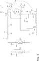
- FIG. 1 schematically illustrates a general configuration of a refrigeration cycle apparatus 1 according to a first embodiment.
- FIG. 1 mainly illustrates a refrigerant circuit 2.
- the refrigeration cycle apparatus 1 is applicable to an air conditioning apparatus configured to perform a cooling operation and a heating operation, a water cooler-heater, and the like.
- the refrigeration cycle apparatus 1 is of a water cooling type.
- a refrigerant flows through the refrigerant circuit 2.
- a heat source-side heat exchanger 23 causes the refrigerant to exchange heat with water flowing through a water circuit 5.
- the refrigeration cycle apparatus 1 includes a heat source unit 20, utilization units 30a and 30b, and a controller 40.
- the refrigeration cycle apparatus 1 includes one or more utilization units.
- the refrigeration cycle apparatus 1 illustrated in FIG. 1 includes two utilization units 30a and 30b.
- the heat source unit 20 includes a compressor 21, an accumulator 26, a four-way switching valve 22, the heat source-side heat exchanger 23, a second electric valve 24, a high-pressure receiver 25, a bypass circuit 27, a third electric valve 28, a plurality of temperature sensors 12 to 17, a pressure sensor 18, a liquid-side shutoff valve 61, and a gas-side shutoff valve 62.
- the four-way switching valve 22, the heat source-side heat exchanger 23, the second electric valve 24, the high-pressure receiver 25, and the liquid-side shutoff valve 61 are connected in this order with refrigerant pipes.
- the refrigerant pipe connecting the second electric valve 24 and the liquid-side shutoff valve 61 is referred to as a liquid pipe 29.
- the compressor 21 is configured to compress a refrigerant.
- the four-way switching valve 22 is configured to switch between a flow of the refrigerant in performing the heating operation (see a broken line in FIG. 1 ) and a flow of the refrigerant in performing the cooling operation (see a solid line in FIG. 1 ).
- the heat source-side heat exchanger 23 is configured to cause the refrigerant flowing through the refrigerant circuit 2 to exchange heat with the water flowing through the water circuit 5.
- the heat source-side heat exchanger 23 is of a plate type.
- the second electric valve 24 is configured to adjust a flow rate of the refrigerant flowing through the refrigerant pipes.
- Each of the high-pressure receiver 25 and the accumulator 26 is configured to temporarily store the refrigerant.
- the pressure sensor 18 is connected to a discharge side of the compressor 21 and is configured to measure a high pressure.
- the temperature sensor 14 is disposed on the refrigerant pipe connecting the heat source-side heat exchanger 23 and the four-way switching valve 22, and is configured to measure a temperature of the refrigerant pipe connected to an inlet side of the heat source-side heat exchanger 23.
- the temperature sensor 15 is disposed on the refrigerant pipe connecting the heat source-side heat exchanger 23 and the second electric valve 24, and is configured to measure a temperature of the refrigerant pipe connected to an outlet side of the heat source-side heat exchanger 23.
- the temperature sensor 16 is disposed on the heat source-side heat exchanger 23 and is configured to measure a temperature of the refrigerant in a gas-liquid two-phase state.
- the temperature sensor 17 is disposed on the liquid pipe 29 and is configured to measure a temperature of the refrigerant pipe (i.e., the liquid pipe 29).
- the bypass circuit 27 connects the refrigerant pipe on the discharge side of the compressor 21 to the refrigerant pipe (the liquid pipe 29) between the second electric valve 24 and the high-pressure receiver 25.
- the third electric valve 28 (a bypass electric valve) is disposed on the bypass circuit 27.
- the third electric valve 28 has an opening degree that is changeable in a sequential or stepwise manner from a closed state to a fully open state. Changing the opening degree of the third electric valve 28 changes the flow rate of the refrigerant flowing through the bypass circuit 27.
- the bypass circuit 27 supplies the high-pressure refrigerant on the discharge side of the compressor 21 to the liquid pipe 29 to maintain the pressure in the liquid pipe 29.
- the bypass circuit 27 is connected to the refrigerant pipe on the discharge side of the compressor 21 and the refrigerant pipe between the second electric valve 24 and the high-pressure receiver 25.
- the connection of the bypass circuit 27 is not limited as long as the bypass circuit 27 is connected to the refrigerant pipe between the second electric valve 24 and the liquid-side shutoff valve 61 for the utilization units 30a and 30b.
- the connection of the bypass circuit 27 is not limited as long as the bypass circuit 27 supplies the high-pressure refrigerant discharged from the compressor 21 to any point between the second electric valve 24 and first electric valves 31a and 31b (to be described later).
- the utilization unit 30a includes the utilization-side heat exchanger 32a and the first electric valve 31a.
- the utilization unit 30b includes the utilization-side heat exchanger 32b and the first electric valve 31b.
- the first electric valves 31a and 31b are connected to the respective utilization-side heat exchangers 32a and 32b with refrigerant pipes.
- the first electric valves 31a and 31b are connected to the liquid-side shutoff valve 61 with refrigerant pipes.
- the utilization-side heat exchangers 32a and 32b are connected to the gas-side shutoff valve 62 with refrigerant pipes.
- Each of the first electric valves 31a and 31b is configured to decompress the refrigerant and adjust a flow rate of the refrigerant.
- Each of the utilization-side heat exchangers 32a and 32b causes the refrigerant to heat exchange with indoor air.
- the controller 40 is a computer.
- the controller 40 includes a processor and a memory.
- the controller 40 is disposed in the heat source unit 20.
- the controller 40 may alternatively be disposed at any position.
- the controller 40 may include a plurality of computers that are disposed separately at different positions and are configured to perform control in cooperation with one another.
- the controller 40 controls the components of the heat source unit 20, the components of the utilization unit 30a, and the components of the utilization unit 30b.
- the controller 40 is connected to the components of the heat source unit 20, the components of the utilization unit 30a, the components of the utilization unit 30b, and the temperature sensors 12 to 17.
- the controller 40 acquires information about an operating state of each component, a measurement value of each sensor, and the like, and controls each component, based on the information.
- each of the utilization-side heat exchangers 32a and 32b functions as a condenser (a radiator), and the heat source-side heat exchanger 23 functions as an evaporator during the heating operation.
- the compressor 21 discharges the refrigerant, the refrigerant flows through the heat source-side heat exchanger 23, the second electric valve 24, the high-pressure receiver 25, the first electric valves 31a and 31b, the utilization-side heat exchangers 32a and 32b, and the accumulator 26, and the compressor 21 sucks in the refrigerant again.
- the heat source-side heat exchanger 23 functions as a condenser (a radiator)
- each of the utilization-side heat exchangers 32a and 32b functions as an evaporator during the cooling operation.
- a water regulator 10 includes a water regulation valve 11, the first temperature sensor 12, the second temperature sensor 13, and the controller 40.
- the heat source-side heat exchanger 23 causes the refrigerant in the refrigeration cycle apparatus 1 to exchange heat with the water circulating in the water circuit 5.
- the heat source-side heat exchanger 23, the water regulation valve 11, a circulation pump 51, and a water heat source (not illustrated) are connected with water pipes.
- the first temperature sensor 12 and the second temperature sensor 13 are disposed on the respective water pipes.
- the first temperature sensor 12 is located outside the heat source unit 20 and is disposed on the water pipe connected to the inlet side of the heat source-side heat exchanger 23.
- the second temperature sensor 13 is located outside the heat source unit 20 and is disposed on the water pipe connected to the outlet side of the heat source-side heat exchanger 23.
- first temperature sensor 12 and second temperature sensor 13 are not limited to those described above.
- first temperature sensor 12 may be located inside the heat source unit 20 and disposed on the water pipe connected to the inlet side of the heat source-side heat exchanger 23.
- the second temperature sensor 13 may be located inside the heat source unit 20 and disposed on the water pipe connected to the outlet side of the heat source-side heat exchanger 23.
- the circulation pump 51 is configured to circulate the water in the water circuit 5.
- the circulation pump 51 has a number of rotations controlled such that a difference between a pressure at an inlet of the circulation pump 51 and a pressure at an outlet of the circulation pump 51 falls within a predetermined range.
- the number of rotations of the circulation pump 51 is controlled independently of the controller 40.
- the circulation pump 51 is disposed in the water circuit 5 and is connected to the outlet side of the heat source-side heat exchanger 23.
- the circulation pump 51 may be disposed in the water circuit 5 and connected to the inlet side of the heat source-side heat exchanger 23.
- the circulation pump 51 may be located at any position as long as it is disposed in the water circuit 5.
- the water regulation valve 11 is configured to regulate the quantity of the water flowing through the water circuit 5.
- the water regulation valve 11 is an opening degree-adjustable electric valve.
- the water regulation valve 11 is controlled by the controller 40.
- the quantity of the water in the water circuit 5 is basically determined in accordance with the number of rotations of the circulation pump 51. However, since the controller 40 is incapable of controlling the circulation pump 51, the water regulation valve 11 rather than the controller 40 controls the quantity of the water in the water circuit 5.
- the water regulation valve 11 changes the quantity of the water in the water circuit 5 to cause a difference between the pressure at the inlet of the circulation pump 51 and the pressure at the outlet of the circulation pump 51.
- the circulation pump 51 controls the quantity of the water circulating in the water circuit 5, based on the pressure difference. As illustrated in FIG.
- the water regulation valve 11 is disposed in the water circuit 5 and is connected to the inlet side of the heat source-side heat exchanger 23.
- the water regulation valve 11 may be disposed in the water circuit 5 and connected to the outlet side of the heat source-side heat exchanger 23.
- the water regulation valve 11 may be located at any position as long as it is disposed in the water circuit 5.
- the water heat source is, for example, a cooling tower for cooling the water flowing through the water circuit 5.
- the first temperature sensor 12 is configured to measure a temperature of the water pipe connected to the inlet side of the heat source-side heat exchanger 23.
- the second temperature sensor 13 is configured to measure a temperature of the water pipe connected to the outlet side of the heat source-side heat exchanger 23.
- Each of the first temperature sensor 12 and the second temperature sensor 13 is a thermistor.
- the controller 40 receives a value of the temperature measured by the first temperature sensor 12 and a value of the temperature measured by the second temperature sensor 13.
- the controller 40 adjusts the opening degree of the water regulation valve 11, based on the values of temperatures measured by the first temperature sensor 12 and second temperature sensor 13, and other kinds of information.
- an initial state refers to a state in which the refrigeration cycle apparatus 1 operates and the circulation pump 51 is driven to circulate the water in the water circuit 5. It is also assumed herein that the refrigeration cycle apparatus 1 carries out the cooling operation. In other words, the heat source-side heat exchanger 23 functions as a condenser. In this state, the controller 40 adjusts the opening degree of the water regulation valve 11.
- step S101 first, the first temperature sensor 12 measures a temperature of the water pipe connected to the inlet side of the heat source-side heat exchanger 23.
- the second temperature sensor 13 measures a temperature of the water pipe connected to the outlet side of the heat source-side heat exchanger 23.
- Each of the first temperature sensor 12 and the second temperature sensor 13 sends the measurement value to the controller 40.
- step S102 and S103 next, the controller 40 calculates a quantity of the water passing the heat source-side heat exchanger 23 per unit time.
- step S102 the controller 40 calculates a refrigerant-side capacity of the refrigerant as a preparation for calculating the quantity of the water.
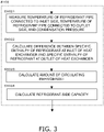
- the refrigerant-side capacity calculation in step S102 is then described in detail with reference to FIG. 3 .
- the controller 40 calculates a difference between the specific enthalpy of the refrigerant at the inlet of the heat source-side heat exchanger 23 and the specific enthalpy of the refrigerant at the outlet of the heat source-side heat exchanger 23 and the amount of the circulating refrigerant, in order to calculate the refrigerant-side capacity.
- the controller 40 calculates the difference between the specific enthalpy of the refrigerant at the inlet of the heat source-side heat exchanger 23 and the specific enthalpy of the refrigerant at the outlet of the heat source-side heat exchanger 23.
- the temperature sensor 14 measures a temperature of the refrigerant pipe connected to the inlet side of the heat source-side heat exchanger 23
- the temperature sensor 15 measures a temperature of the refrigerant pipe connected to the outlet side of the heat source-side heat exchanger 23.
- the pressure sensor 18 measures a condensation pressure (a discharge pressure).
- the temperature sensor 16 may measure a temperature of the refrigerant in a gas-liquid two-phase state in the heat source-side heat exchanger 23 (i.e., a condensation temperature) and estimate a condensation pressure from a physical property value of the refrigerant.
- step S1022 next, the controller 40 calculates the difference between the specific enthalpy of the refrigerant at the inlet of the heat source-side heat exchanger 23 and the specific enthalpy of the refrigerant at the outlet of the heat source-side heat exchanger 23, using the values measured in step S1021.
- the controller 40 calculates a specific enthalpy of the refrigerant at the inlet of the heat source-side heat exchanger 23, from a temperature of the refrigerant pipe connected to the inlet side of the heat source-side heat exchanger 23 and a condensation pressure, using a Mollier diagram for each refrigerant.
- the controller 40 calculates a specific enthalpy of the refrigerant at the outlet of the heat source-side heat exchanger 23, from a temperature of the refrigerant pipe connected to the outlet side of the heat source-side heat exchanger 23 and the condensation pressure, using the Mollier diagram for each refrigerant.
- the controller 40 calculates the difference between the specific enthalpy of the refrigerant at the inlet of the heat source-side heat exchanger 23 and the specific enthalpy of the refrigerant at the outlet of the heat source-side heat exchanger 23, from Equation (1).
- step S1023 next, the controller 40 estimates the amount of the circulating refrigerant.
- the controller 40 stores a regression formula prepared in advance for estimating the amount of the circulating refrigerant.
- the regression formula is prepared as follows. Parameter values are measured in such a manner that the cooling operation is carried out while operating conditions of the refrigeration cycle apparatus are changed. Parameters include a condensation pressure, an evaporation pressure, a suction temperature, and a number of rotations of a compressor. As for the condensation pressure and the evaporation pressure, a condensation temperature and an evaporation temperature may be used in a manner similar to that described above.
- the regression formula is prepared based on an amount of a circulating refrigerant that is actually measured while changing the parameters. In step S1023, the controller 40 substitutes the measured parameter values in the regression formula prepared in advance, thereby calculating the amount of the circulating refrigerant [kg/s].
- the controller 40 calculates a refrigerant-side capacity [kW] from Equation (2), using the difference between the specific enthalpy of the refrigerant at the inlet of the heat source-side heat exchanger 23 and the specific enthalpy of the refrigerant at the outlet of the heat source-side heat exchanger 23 [kJ/kg] (step S1022) and the amount of the circulating refrigerant [kg/s] (step S1023).
- refrigerant ⁇ side capacity kW amount of circulating refrigerant kg / s ⁇ difference between the specific enthalpy of the refroigerant at the inlet of heat exchanger and the specific enthaply of the refrigerant at the outlet of heat exchanger kJ / kg
- the controller 40 terminates the refrigerant-side capacity calculation in step S102.
- the controller 40 calculates the quantity of the water, using the measured value of the temperature of the water pipe connected to the inlet side of the heat source-side heat exchanger 23 (step S101), the measured value of the temperature of the water pipe connected to the outlet side of the heat source-side heat exchanger 23 (step S101), and the calculation result of the refrigerant-side capacity (step S102).
- the controller 40 calculates a specific heat of the water at the inlet of the heat source-side heat exchanger 23 [kJ/(kg ⁇ K)] and a density of the water at the inlet of the heat source-side heat exchanger 23 [kg/m 3 ] from the temperature of the water pipe connected to the inlet side of the heat source-side heat exchanger 23 (step S101), using a physical property value of the water.
- the controller 40 calculates a specific heat of the water at the outlet of the heat source-side heat exchanger 23 [kJ/(kg ⁇ K)] and a density of the water at the outlet of the heat source-side heat exchanger 23 [kg/m 3 ] from the temperature of the water pipe connected to the outlet side of the heat source-side heat exchanger 23 (step S101), using the physical property value of the water.
- the controller 40 calculates the quantity of the water [m 3 /s] from Equation (3), using the temperature of the water pipe connected to the outlet side of the heat source-side heat exchanger 23 [°C] (step S101), the temperature of the water pipe connected to the inlet side of the heat source-side heat exchanger 23 [°C] (step S101), and the refrigerant-side capacity [kW] (step S102).
- step S104 next, the controller 40 determines whether the current quantity of the water thus calculated falls within an allowable range.
- the control proceeds to step S105.
- the control proceeds to step S112.
- step S112 the controller 40 decreases the opening degree of the water regulation valve 11, and then terminates the control.
- step S111 the controller 40 increases the opening degree of the water regulation valve 11, and then terminates the control.
- step S105 the controller 40 determines whether the difference between the temperature of the water pipe connected to the inlet side of the heat source-side heat exchanger 23 and the temperature of the water pipe connected to the outlet side of the heat source-side heat exchanger 23 (step S101) falls within a target range.
- the controller 40 maintains the opening degree of the water regulation valve 11 (S110), and then terminates the control.
- the controller 40 increases the opening degree of the water regulation valve 11 (Sill), and then terminates the control.
- the controller 40 decreases the opening degree of the water regulation valve 11 (S112), and then terminates the control.
- the controller 40 carries out steps S101 to S110 (or S111 or S112), thereby terminating the series of control.
- the controller 40 carries out steps S101 to S110 (or S111 or S112) repeatedly until the quantity of the water falls within the allowable range in step S104, the difference falls within the target range in step S105, and the opening degree of the water regulation valve is held in step S110.
- the controller 40 may hold the opening degree of the water regulation valve 11 in a proper state by repeatedly carrying out steps S101 to S110 (or S111 or S112) every predetermined time even after the quantity of the water falls within the allowable range in step S104, the difference falls within the target range in step S105, and the opening degree of the water regulation valve is held in step S110.
- the first embodiment provides a water regulator 10 for controlling a quantity of water flowing through water pipes of a water circuit 5 in a refrigeration cycle apparatus (1) including a refrigerant circuit (2) through which a refrigerant flows, a circulation pump (51) having a number of rotations controlled such that a difference between a pressure at an inlet of the circulation pump and a pressure at an outlet of the circulation pump falls within a predetermined range, the circulation pump being configured to circulate the water in the water pipes, and a heat exchanger (23) configured to cause the refrigerant flowing through the refrigerant circuit to exchange heat with the water flowing through the water pipes.
- the water regulator 10 includes: a water regulation valve 11 configured to regulate the quantity of the water flowing through the water pipes; a first temperature sensor 12 configured to measure a temperature of one of the water pipes which is connected to an inlet of the heat exchanger 23; a second temperature sensor 13 configured to measure a temperature of one of the water pipes which is connected to an outlet of the heat exchanger 23; and a controller 40 configured to control an opening degree of the water regulation valve 11, based on a difference between the temperature measured by the first temperature sensor 12 and the temperature measured by the second temperature sensor 13.
- the water regulation valve 11 of the water regulator 10 regulates the quantity of the water flowing through the water pipes of the water circuit 5.
- the water regulator 10 thus indirectly controls the number of rotations of the circulation pump 51 in accordance with a load to be applied to the refrigeration cycle apparatus 1. This configuration therefore improves the energy conservation of the entire apparatus.
- controller 40 of the water regulator 10 controls the opening degree of the water regulation valve 11 such that the difference between the temperature measured by the first temperature sensor 12 and the temperature measured by the second temperature sensor 13 falls within the predetermined range. This configuration therefore enables optimization of the quantity of the water circulating in the water circuit 5.
- the controller 40 controls the opening degree of the water regulation valve 11 during a normal operation such as the cooling operation or the heating operation.
- a normal operation such as the cooling operation or the heating operation.
- This configuration therefore enables optimization of the quantity of the water circulating in the water circuit 5 during the normal operation.
- this configuration enables optimization of the quantity of the water during the normal operation in such a manner that the control is performed repeatedly every predetermined time.
- the controller 40 of the water regulator 10 adjusts the opening degree of the water regulation valve 11 such that the quantity of the water flowing through the water pipes of the water circuit 5 falls within the predetermined range (S104).
- the quantity of the water is not actually measured, but is calculated by computation (S103).
- the water regulator 10 adjusts the opening degree of the water regulation valve 11, based on the quantity of the water calculated by computation, in addition to the difference between the temperature of the water pipe connected to the inlet of the heat source-side heat exchanger 23 and the temperature of the water pipe connected to the outlet of the heat source-side heat exchanger 23.
- the water regulator 10 therefore controls the quantity of the water more properly. Since the quantity of the water is calculated by computation, this configuration eliminates a necessity of an expensive water sensor.
- the controller 40 calculates the quantity of the water in step S103, based on the refrigerant-side capacity of the refrigerant calculated in step S102.
- the controller 40 calculates the quantity of the water depending on an amount of heat exchange in the refrigeration cycle apparatus 1, and controls the quantity of the water circulating in the water circuit 5, based on the quantity of the water thus calculated. This configuration therefore enables control on the quantity of the water more properly.
- the controller 40 calculates the refrigerant-side capacity of the refrigerant, based on the amount of the circulating refrigerant and the difference between the specific enthalpy of the refrigerant at the refrigerant inlet of the heat source-side heat exchanger 23 and the specific enthalpy of the refrigerant at the refrigerant outlet of the heat source-side heat exchanger 23 (see Equation (2)).
- the controller 40 of the water regulator 10 adjusts the opening degree of the water regulation valve 11 such that the quantity of the water flowing through the water pipes of the water circuit 5 falls within the predetermined range (S104), and then controls the opening degree of the water regulation valve 11, based on the difference between the temperature of the water pipe connected to the inlet of the heat source-side heat exchanger 23 and the temperature of the water pipe connected to the outlet of the heat source-side heat exchanger 23 (S105). This control thus optimizes the quantity of the water flowing through the water pipes of the water circuit 5.
- a water regulator 10 according to Modification 1A is equal in configuration to that according to the first embodiment.
- a method of opening degree control for a water regulation valve 11 according to Modification 1A is equal to that according to the first embodiment, except the method of calculating the amount of the circulating refrigerant in step S1023.
- a description will be given of a method of calculating an amount of a circulating refrigerant according to Modification 1A.
- the controller 40 calculates the amount of the circulating refrigerant, using parameters including parameters indicating a state of an operation carried out by the refrigeration cycle apparatus 1 and parameters indicating characteristics of the compressor 21.
- the controller 40 measures a refrigerant evaporation pressure and a refrigerant suction temperature in the compressor 21.
- the refrigerant evaporation pressure and the refrigerant suction temperature are the parameters indicating the state of the operation carried out by the refrigeration cycle apparatus 1.
- the controller 40 calculates a refrigerant suction density (kg/m 3 ) from the refrigerant evaporation pressure and the refrigerant suction temperature.
- the controller 40 calculates an amount of the circulating refrigerant [kg/s] from Equation (4), using a volumetric efficiency [%], a piston displacement [m 3 /rev], and a current number of rotations of the compressor 21 [rps].
- volumetric efficiency [%] and the piston displacement [m 3 /rev] are parameters indicating the characteristics of the compressor 21.
- amount of circulating refrigerant kg / s volumetric efficiency % ⁇ piston displacement m 3 / rev ⁇ number of rotations of compressor rps
- Patent Literature 1 JP 2008-075948 A
Landscapes
- Engineering & Computer Science (AREA)
- Mechanical Engineering (AREA)
- General Engineering & Computer Science (AREA)
- Chemical & Material Sciences (AREA)
- Combustion & Propulsion (AREA)
- Physics & Mathematics (AREA)
- Thermal Sciences (AREA)
- Life Sciences & Earth Sciences (AREA)
- Sustainable Development (AREA)
- Air Conditioning Control Device (AREA)
- Heat-Pump Type And Storage Water Heaters (AREA)
Abstract
Description
- Embodiments disclosed herein relate to a water regulator in a refrigeration cycle apparatus.
- As for air conditioning apparatuses for conditioning indoor air with a refrigerant, an air conditioning apparatus of a water cooling type has been known, which is configured to cool or heat a heat source-side heat exchanger with water. Patent Literature 1 (
JP 2008-075948 A - In general, water pipes in which cooling water for use in heat exchange circulates and a circulation pump for controlling the circulation of the cooling water in the water pipes are procured locally in installing an air conditioning apparatus of a water cooling type. Consequently, the air conditioning apparatus of the water cooling type is incapable of directly controlling the circulation pump. Hence, the present disclosure provides a controller capable of controlling a quantity of cooling water circulating in water pipes, without directly controlling a circulation pump.
- A first aspect provides a water regulator for controlling a quantity of water flowing through water pipes in a refrigeration cycle apparatus. The refrigeration cycle apparatus includes a refrigerant circuit through which a refrigerant flows, a circulation pump having a number of rotations controlled such that a difference between a pressure at an inlet of the circulation pump and a pressure at an outlet of the circulation pump falls within a predetermined range, the circulation pump being configured to circulate the water in the water pipes, and a heat exchanger configured to cause the refrigerant flowing through the refrigerant circuit to exchange heat with the water flowing through the water pipes. The water regulator includes: a water regulation valve configured to regulate the quantity of the water flowing through the water pipes; a first temperature sensor configured to measure a temperature of one of the water pipes which is connected to an inlet of the heat exchanger; a second temperature sensor configured to measure a temperature of one of the water pipes which is connected to an outlet of the heat exchanger; and a controller configured to control an opening degree of the water regulation valve, based on a difference between the temperature measured by the first temperature sensor and the temperature measured by the second temperature sensor.
- According to the first aspect, the water regulation valve of the water regulator controls the quantity of the water flowing through the water pipes. The water regulator therefore controls the quantity of the cooling water circulating in the water pipes, without directly controlling the circulation pump.
- A second aspect provides the water regulator according to the first aspect, in which the controller controls the opening degree of the water regulation valve such that the difference between the temperature measured by the first temperature sensor and the temperature measured by the second temperature sensor falls within a predetermined range.
- A third aspect provides the water regulator according to the first or second aspect, in which the controller adjusts the opening degree of the water regulation valve such that the quantity of the water flowing through the water pipes falls within a predetermined range.
- A fourth aspect provides the water regulator according to the third aspect, in which the controller calculates the quantity of the water, based on a refrigerant-side capacity of the refrigerant.
- According to the fourth aspect, the controller of the water regulator calculates the quantity of the water, based on the refrigerant-side capacity of the refrigerant, and adjusts the opening degree of the water regulation valve such that the quantity of the water falls within the predetermined range. The water regulator therefore controls the quantity of the water within an appropriate range.
- A fifth aspect provides the water regulator according to the fourth aspect, in which the controller calculates the refrigerant-side capacity of the refrigerant, based on an amount of the circulating refrigerant and a change between the enthalpy of the refrigerant at the refrigerant inlet of the heat exchanger and the enthalpy of the refrigerant at the refrigerant outlet of the heat exchanger.
- A sixth aspect provides the water regulator according to any of the third to fifth aspects, in which the controller adjusts the opening degree of the water regulation valve such that the quantity of the water flowing through the water pipes falls within the predetermined range. The controller then controls the opening degree of the water regulation valve, based on the difference between the temperature measured by the first temperature sensor and the temperature measured by the second temperature sensor.
- According to the sixth aspect, the controller of the water regulator adjusts the opening degree of the water regulation valve such that the quantity of the water falls within the predetermined range, and then controls the opening degree of the water regulation valve, based on the difference between the temperature measured by the first temperature sensor and the temperature measured by the second temperature sensor. The water regulator therefore controls the opening degree of the water regulation valve more properly.
- A seventh aspect provides the water regulator according to any of the first to sixth aspects, in which the heat exchanger serves as a heat source-side heat exchanger for the refrigeration cycle apparatus. The controller and the heat exchanger are disposed in a heat source unit of the refrigeration cycle apparatus.
-
-
FIG. 1 is a diagram of a general configuration of a refrigeration cycle apparatus 1 including awater regulator 10 and a refrigerant circuit. -
FIG. 2 is a flowchart of opening degree control for awater regulation valve 11. -
FIG. 3 is a flowchart of sub-steps of step S102 (refrigerant capacity calculation) inFIG. 2 . -
FIG. 1 schematically illustrates a general configuration of a refrigeration cycle apparatus 1 according to a first embodiment.FIG. 1 mainly illustrates arefrigerant circuit 2. The refrigeration cycle apparatus 1 is applicable to an air conditioning apparatus configured to perform a cooling operation and a heating operation, a water cooler-heater, and the like. The refrigeration cycle apparatus 1 is of a water cooling type. A refrigerant flows through therefrigerant circuit 2. A heat source-side heat exchanger 23 causes the refrigerant to exchange heat with water flowing through awater circuit 5. - The refrigeration cycle apparatus 1 according to the first embodiment includes a
heat source unit 20,utilization units controller 40. The refrigeration cycle apparatus 1 includes one or more utilization units. The refrigeration cycle apparatus 1 illustrated inFIG. 1 includes twoutilization units - The
heat source unit 20 includes acompressor 21, anaccumulator 26, a four-way switching valve 22, the heat source-side heat exchanger 23, a secondelectric valve 24, a high-pressure receiver 25, abypass circuit 27, a thirdelectric valve 28, a plurality oftemperature sensors 12 to 17, apressure sensor 18, a liquid-side shutoff valve 61, and a gas-side shutoff valve 62. In theheat source unit 20, the four-way switching valve 22, the heat source-side heat exchanger 23, the secondelectric valve 24, the high-pressure receiver 25, and the liquid-side shutoff valve 61 are connected in this order with refrigerant pipes. The refrigerant pipe connecting the secondelectric valve 24 and the liquid-side shutoff valve 61 is referred to as aliquid pipe 29. - The
compressor 21 is configured to compress a refrigerant. The four-way switching valve 22 is configured to switch between a flow of the refrigerant in performing the heating operation (see a broken line inFIG. 1 ) and a flow of the refrigerant in performing the cooling operation (see a solid line inFIG. 1 ). The heat source-side heat exchanger 23 is configured to cause the refrigerant flowing through therefrigerant circuit 2 to exchange heat with the water flowing through thewater circuit 5. The heat source-side heat exchanger 23 is of a plate type. The secondelectric valve 24 is configured to adjust a flow rate of the refrigerant flowing through the refrigerant pipes. Each of the high-pressure receiver 25 and theaccumulator 26 is configured to temporarily store the refrigerant. - The
pressure sensor 18 is connected to a discharge side of thecompressor 21 and is configured to measure a high pressure. Thetemperature sensor 14 is disposed on the refrigerant pipe connecting the heat source-side heat exchanger 23 and the four-way switching valve 22, and is configured to measure a temperature of the refrigerant pipe connected to an inlet side of the heat source-side heat exchanger 23. Thetemperature sensor 15 is disposed on the refrigerant pipe connecting the heat source-side heat exchanger 23 and the secondelectric valve 24, and is configured to measure a temperature of the refrigerant pipe connected to an outlet side of the heat source-side heat exchanger 23. Thetemperature sensor 16 is disposed on the heat source-side heat exchanger 23 and is configured to measure a temperature of the refrigerant in a gas-liquid two-phase state. The temperature sensor 17 is disposed on theliquid pipe 29 and is configured to measure a temperature of the refrigerant pipe (i.e., the liquid pipe 29). - The
bypass circuit 27 connects the refrigerant pipe on the discharge side of thecompressor 21 to the refrigerant pipe (the liquid pipe 29) between the secondelectric valve 24 and the high-pressure receiver 25. The third electric valve 28 (a bypass electric valve) is disposed on thebypass circuit 27. The thirdelectric valve 28 has an opening degree that is changeable in a sequential or stepwise manner from a closed state to a fully open state. Changing the opening degree of the thirdelectric valve 28 changes the flow rate of the refrigerant flowing through thebypass circuit 27. During the cooling operation (in which a utilization-side heat exchanger serves as an evaporator), when the pressure in theliquid pipe 29 decreases, thebypass circuit 27 supplies the high-pressure refrigerant on the discharge side of thecompressor 21 to theliquid pipe 29 to maintain the pressure in theliquid pipe 29. Thebypass circuit 27 is connected to the refrigerant pipe on the discharge side of thecompressor 21 and the refrigerant pipe between the secondelectric valve 24 and the high-pressure receiver 25. The connection of thebypass circuit 27 is not limited as long as thebypass circuit 27 is connected to the refrigerant pipe between the secondelectric valve 24 and the liquid-side shutoff valve 61 for theutilization units bypass circuit 27 is not limited as long as thebypass circuit 27 supplies the high-pressure refrigerant discharged from thecompressor 21 to any point between the secondelectric valve 24 and firstelectric valves - The
utilization unit 30a includes the utilization-side heat exchanger 32a and the firstelectric valve 31a. Theutilization unit 30b includes the utilization-side heat exchanger 32b and the firstelectric valve 31b. The firstelectric valves side heat exchangers electric valves side shutoff valve 61 with refrigerant pipes. The utilization-side heat exchangers side shutoff valve 62 with refrigerant pipes. - Each of the first
electric valves side heat exchangers - The
controller 40 is a computer. Thecontroller 40 includes a processor and a memory. In the first embodiment, thecontroller 40 is disposed in theheat source unit 20. Thecontroller 40 may alternatively be disposed at any position. Thecontroller 40 may include a plurality of computers that are disposed separately at different positions and are configured to perform control in cooperation with one another. Thecontroller 40 controls the components of theheat source unit 20, the components of theutilization unit 30a, and the components of theutilization unit 30b. Thecontroller 40 is connected to the components of theheat source unit 20, the components of theutilization unit 30a, the components of theutilization unit 30b, and thetemperature sensors 12 to 17. Thecontroller 40 acquires information about an operating state of each component, a measurement value of each sensor, and the like, and controls each component, based on the information. - During the heating operation, the
compressor 21 discharges the refrigerant, the refrigerant flows through the utilization-side heat exchangers electric valves pressure receiver 25, the secondelectric valve 24, the heat source-side heat exchanger 23, and theaccumulator 26, and thecompressor 21 sucks in the refrigerant again. In other word, each of the utilization-side heat exchangers side heat exchanger 23 functions as an evaporator during the heating operation. - During the cooling operation, the
compressor 21 discharges the refrigerant, the refrigerant flows through the heat source-side heat exchanger 23, the secondelectric valve 24, the high-pressure receiver 25, the firstelectric valves side heat exchangers accumulator 26, and thecompressor 21 sucks in the refrigerant again. In other words, the heat source-side heat exchanger 23 functions as a condenser (a radiator), and each of the utilization-side heat exchangers - A
water regulator 10 includes awater regulation valve 11, thefirst temperature sensor 12, thesecond temperature sensor 13, and thecontroller 40. - As described above, the heat source-
side heat exchanger 23 causes the refrigerant in the refrigeration cycle apparatus 1 to exchange heat with the water circulating in thewater circuit 5. In thewater circuit 5, the heat source-side heat exchanger 23, thewater regulation valve 11, acirculation pump 51, and a water heat source (not illustrated) are connected with water pipes. Thefirst temperature sensor 12 and thesecond temperature sensor 13 are disposed on the respective water pipes. Thefirst temperature sensor 12 is located outside theheat source unit 20 and is disposed on the water pipe connected to the inlet side of the heat source-side heat exchanger 23. Thesecond temperature sensor 13 is located outside theheat source unit 20 and is disposed on the water pipe connected to the outlet side of the heat source-side heat exchanger 23. The positions of thefirst temperature sensor 12 andsecond temperature sensor 13 are not limited to those described above. For example, thefirst temperature sensor 12 may be located inside theheat source unit 20 and disposed on the water pipe connected to the inlet side of the heat source-side heat exchanger 23. Thesecond temperature sensor 13 may be located inside theheat source unit 20 and disposed on the water pipe connected to the outlet side of the heat source-side heat exchanger 23. - The
circulation pump 51 is configured to circulate the water in thewater circuit 5. Thecirculation pump 51 has a number of rotations controlled such that a difference between a pressure at an inlet of thecirculation pump 51 and a pressure at an outlet of thecirculation pump 51 falls within a predetermined range. In the first embodiment, the number of rotations of thecirculation pump 51 is controlled independently of thecontroller 40. As illustrated inFIG. 1 , thecirculation pump 51 is disposed in thewater circuit 5 and is connected to the outlet side of the heat source-side heat exchanger 23. Thecirculation pump 51 may be disposed in thewater circuit 5 and connected to the inlet side of the heat source-side heat exchanger 23. Thecirculation pump 51 may be located at any position as long as it is disposed in thewater circuit 5. - The
water regulation valve 11 is configured to regulate the quantity of the water flowing through thewater circuit 5. Thewater regulation valve 11 is an opening degree-adjustable electric valve. Thewater regulation valve 11 is controlled by thecontroller 40. The quantity of the water in thewater circuit 5 is basically determined in accordance with the number of rotations of thecirculation pump 51. However, since thecontroller 40 is incapable of controlling thecirculation pump 51, thewater regulation valve 11 rather than thecontroller 40 controls the quantity of the water in thewater circuit 5. Thewater regulation valve 11 changes the quantity of the water in thewater circuit 5 to cause a difference between the pressure at the inlet of thecirculation pump 51 and the pressure at the outlet of thecirculation pump 51. Thecirculation pump 51 controls the quantity of the water circulating in thewater circuit 5, based on the pressure difference. As illustrated inFIG. 1 , thewater regulation valve 11 is disposed in thewater circuit 5 and is connected to the inlet side of the heat source-side heat exchanger 23. Thewater regulation valve 11 may be disposed in thewater circuit 5 and connected to the outlet side of the heat source-side heat exchanger 23. Thewater regulation valve 11 may be located at any position as long as it is disposed in thewater circuit 5. - The water heat source is, for example, a cooling tower for cooling the water flowing through the
water circuit 5. - The
first temperature sensor 12 is configured to measure a temperature of the water pipe connected to the inlet side of the heat source-side heat exchanger 23. Thesecond temperature sensor 13 is configured to measure a temperature of the water pipe connected to the outlet side of the heat source-side heat exchanger 23. Each of thefirst temperature sensor 12 and thesecond temperature sensor 13 is a thermistor. Thecontroller 40 receives a value of the temperature measured by thefirst temperature sensor 12 and a value of the temperature measured by thesecond temperature sensor 13. - In the refrigeration cycle apparatus 1, the
controller 40 adjusts the opening degree of thewater regulation valve 11, based on the values of temperatures measured by thefirst temperature sensor 12 andsecond temperature sensor 13, and other kinds of information. - With reference to
FIG. 2 , next, a description will be given of a flow of opening degree control for thewater regulation valve 11. - It is assumed herein that an initial state refers to a state in which the refrigeration cycle apparatus 1 operates and the
circulation pump 51 is driven to circulate the water in thewater circuit 5. It is also assumed herein that the refrigeration cycle apparatus 1 carries out the cooling operation. In other words, the heat source-side heat exchanger 23 functions as a condenser. In this state, thecontroller 40 adjusts the opening degree of thewater regulation valve 11. - In step S101, first, the
first temperature sensor 12 measures a temperature of the water pipe connected to the inlet side of the heat source-side heat exchanger 23. Thesecond temperature sensor 13 measures a temperature of the water pipe connected to the outlet side of the heat source-side heat exchanger 23. Each of thefirst temperature sensor 12 and thesecond temperature sensor 13 sends the measurement value to thecontroller 40. - In steps S102 and S103, next, the
controller 40 calculates a quantity of the water passing the heat source-side heat exchanger 23 per unit time. - In step S102, the
controller 40 calculates a refrigerant-side capacity of the refrigerant as a preparation for calculating the quantity of the water. The refrigerant-side capacity calculation in step S102 is then described in detail with reference toFIG. 3 . - In the first embodiment, the
controller 40 calculates a difference between the specific enthalpy of the refrigerant at the inlet of the heat source-side heat exchanger 23 and the specific enthalpy of the refrigerant at the outlet of the heat source-side heat exchanger 23 and the amount of the circulating refrigerant, in order to calculate the refrigerant-side capacity. - In steps S1021 and S1022, the
controller 40 calculates the difference between the specific enthalpy of the refrigerant at the inlet of the heat source-side heat exchanger 23 and the specific enthalpy of the refrigerant at the outlet of the heat source-side heat exchanger 23. In step S1021, thetemperature sensor 14 measures a temperature of the refrigerant pipe connected to the inlet side of the heat source-side heat exchanger 23, and thetemperature sensor 15 measures a temperature of the refrigerant pipe connected to the outlet side of the heat source-side heat exchanger 23. Thepressure sensor 18 measures a condensation pressure (a discharge pressure). Instead of directly measuring the condensation pressure, thetemperature sensor 16 may measure a temperature of the refrigerant in a gas-liquid two-phase state in the heat source-side heat exchanger 23 (i.e., a condensation temperature) and estimate a condensation pressure from a physical property value of the refrigerant. - In step S1022, next, the
controller 40 calculates the difference between the specific enthalpy of the refrigerant at the inlet of the heat source-side heat exchanger 23 and the specific enthalpy of the refrigerant at the outlet of the heat source-side heat exchanger 23, using the values measured in step S1021. A more specific description will be given below. First, thecontroller 40 calculates a specific enthalpy of the refrigerant at the inlet of the heat source-side heat exchanger 23, from a temperature of the refrigerant pipe connected to the inlet side of the heat source-side heat exchanger 23 and a condensation pressure, using a Mollier diagram for each refrigerant. Next, thecontroller 40 calculates a specific enthalpy of the refrigerant at the outlet of the heat source-side heat exchanger 23, from a temperature of the refrigerant pipe connected to the outlet side of the heat source-side heat exchanger 23 and the condensation pressure, using the Mollier diagram for each refrigerant. Next, thecontroller 40 calculates the difference between the specific enthalpy of the refrigerant at the inlet of the heat source-side heat exchanger 23 and the specific enthalpy of the refrigerant at the outlet of the heat source-side heat exchanger 23, from Equation (1).
- In step S1023, next, the
controller 40 estimates the amount of the circulating refrigerant. Thecontroller 40 stores a regression formula prepared in advance for estimating the amount of the circulating refrigerant. The regression formula is prepared as follows. Parameter values are measured in such a manner that the cooling operation is carried out while operating conditions of the refrigeration cycle apparatus are changed. Parameters include a condensation pressure, an evaporation pressure, a suction temperature, and a number of rotations of a compressor. As for the condensation pressure and the evaporation pressure, a condensation temperature and an evaporation temperature may be used in a manner similar to that described above. The regression formula is prepared based on an amount of a circulating refrigerant that is actually measured while changing the parameters. In step S1023, thecontroller 40 substitutes the measured parameter values in the regression formula prepared in advance, thereby calculating the amount of the circulating refrigerant [kg/s]. - In S1024, the
controller 40 calculates a refrigerant-side capacity [kW] from Equation (2), using the difference between the specific enthalpy of the refrigerant at the inlet of the heat source-side heat exchanger 23 and the specific enthalpy of the refrigerant at the outlet of the heat source-side heat exchanger 23 [kJ/kg] (step S1022) and the amount of the circulating refrigerant [kg/s] (step S1023).
- Through the measurement and calculation described above, the
controller 40 terminates the refrigerant-side capacity calculation in step S102. - Next, the
controller 40 calculates the quantity of the water, using the measured value of the temperature of the water pipe connected to the inlet side of the heat source-side heat exchanger 23 (step S101), the measured value of the temperature of the water pipe connected to the outlet side of the heat source-side heat exchanger 23 (step S101), and the calculation result of the refrigerant-side capacity (step S102). First, thecontroller 40 calculates a specific heat of the water at the inlet of the heat source-side heat exchanger 23 [kJ/(kg·K)] and a density of the water at the inlet of the heat source-side heat exchanger 23 [kg/m3] from the temperature of the water pipe connected to the inlet side of the heat source-side heat exchanger 23 (step S101), using a physical property value of the water. Likewise, thecontroller 40 calculates a specific heat of the water at the outlet of the heat source-side heat exchanger 23 [kJ/(kg·K)] and a density of the water at the outlet of the heat source-side heat exchanger 23 [kg/m3] from the temperature of the water pipe connected to the outlet side of the heat source-side heat exchanger 23 (step S101), using the physical property value of the water. Next, thecontroller 40 calculates the quantity of the water [m3/s] from Equation (3), using the temperature of the water pipe connected to the outlet side of the heat source-side heat exchanger 23 [°C] (step S101), the temperature of the water pipe connected to the inlet side of the heat source-side heat exchanger 23 [°C] (step S101), and the refrigerant-side capacity [kW] (step S102).
- In step S104, next, the
controller 40 determines whether the current quantity of the water thus calculated falls within an allowable range. When the current quantity of the water falls within the allowable range, the control proceeds to step S105. When the current quantity of the water exceeds an upper limit of the allowable range, the control proceeds to step S112. In step S112, thecontroller 40 decreases the opening degree of thewater regulation valve 11, and then terminates the control. When the current quantity of the water falls below a lower limit of the allowable range, the control proceeds to step S111. In step S111, thecontroller 40 increases the opening degree of thewater regulation valve 11, and then terminates the control. - In step S105, the
controller 40 determines whether the difference between the temperature of the water pipe connected to the inlet side of the heat source-side heat exchanger 23 and the temperature of the water pipe connected to the outlet side of the heat source-side heat exchanger 23 (step S101) falls within a target range. When the difference thus measured falls within the target range, thecontroller 40 maintains the opening degree of the water regulation valve 11 (S110), and then terminates the control. When the difference thus measured exceeds an upper limit of the target range, thecontroller 40 increases the opening degree of the water regulation valve 11 (Sill), and then terminates the control. When the difference thus measured falls below a lower limit of the target range, thecontroller 40 decreases the opening degree of the water regulation valve 11 (S112), and then terminates the control. - As described above, the
controller 40 carries out steps S101 to S110 (or S111 or S112), thereby terminating the series of control. Preferably, thecontroller 40 carries out steps S101 to S110 (or S111 or S112) repeatedly until the quantity of the water falls within the allowable range in step S104, the difference falls within the target range in step S105, and the opening degree of the water regulation valve is held in step S110. Alternatively, thecontroller 40 may hold the opening degree of thewater regulation valve 11 in a proper state by repeatedly carrying out steps S101 to S110 (or S111 or S112) every predetermined time even after the quantity of the water falls within the allowable range in step S104, the difference falls within the target range in step S105, and the opening degree of the water regulation valve is held in step S110. - (4-1) The first embodiment provides a
water regulator 10 for controlling a quantity of water flowing through water pipes of awater circuit 5 in a refrigeration cycle apparatus (1) including a refrigerant circuit (2) through which a refrigerant flows, a circulation pump (51) having a number of rotations controlled such that a difference between a pressure at an inlet of the circulation pump and a pressure at an outlet of the circulation pump falls within a predetermined range, the circulation pump being configured to circulate the water in the water pipes, and a heat exchanger (23) configured to cause the refrigerant flowing through the refrigerant circuit to exchange heat with the water flowing through the water pipes. Thewater regulator 10 includes: awater regulation valve 11 configured to regulate the quantity of the water flowing through the water pipes; afirst temperature sensor 12 configured to measure a temperature of one of the water pipes which is connected to an inlet of theheat exchanger 23; asecond temperature sensor 13 configured to measure a temperature of one of the water pipes which is connected to an outlet of theheat exchanger 23; and acontroller 40 configured to control an opening degree of thewater regulation valve 11, based on a difference between the temperature measured by thefirst temperature sensor 12 and the temperature measured by thesecond temperature sensor 13. - According to the first embodiment, the
water regulation valve 11 of thewater regulator 10 regulates the quantity of the water flowing through the water pipes of thewater circuit 5. Thewater regulator 10 thus indirectly controls the number of rotations of thecirculation pump 51 in accordance with a load to be applied to the refrigeration cycle apparatus 1. This configuration therefore improves the energy conservation of the entire apparatus. - In addition, the
controller 40 of thewater regulator 10 controls the opening degree of thewater regulation valve 11 such that the difference between the temperature measured by thefirst temperature sensor 12 and the temperature measured by thesecond temperature sensor 13 falls within the predetermined range. This configuration therefore enables optimization of the quantity of the water circulating in thewater circuit 5. - According to the first embodiment, the
controller 40 controls the opening degree of thewater regulation valve 11 during a normal operation such as the cooling operation or the heating operation. This configuration therefore enables optimization of the quantity of the water circulating in thewater circuit 5 during the normal operation. In addition, this configuration enables optimization of the quantity of the water during the normal operation in such a manner that the control is performed repeatedly every predetermined time. - (4-2) According to the first embodiment, the
controller 40 of thewater regulator 10 adjusts the opening degree of thewater regulation valve 11 such that the quantity of the water flowing through the water pipes of thewater circuit 5 falls within the predetermined range (S104). The quantity of the water is not actually measured, but is calculated by computation (S103). - According to the first embodiment, the
water regulator 10 adjusts the opening degree of thewater regulation valve 11, based on the quantity of the water calculated by computation, in addition to the difference between the temperature of the water pipe connected to the inlet of the heat source-side heat exchanger 23 and the temperature of the water pipe connected to the outlet of the heat source-side heat exchanger 23. Thewater regulator 10 therefore controls the quantity of the water more properly. Since the quantity of the water is calculated by computation, this configuration eliminates a necessity of an expensive water sensor. - (4-3) The
controller 40 calculates the quantity of the water in step S103, based on the refrigerant-side capacity of the refrigerant calculated in step S102. - In other words, the
controller 40 calculates the quantity of the water depending on an amount of heat exchange in the refrigeration cycle apparatus 1, and controls the quantity of the water circulating in thewater circuit 5, based on the quantity of the water thus calculated. This configuration therefore enables control on the quantity of the water more properly. - According to the first embodiment, the
controller 40 calculates the refrigerant-side capacity of the refrigerant, based on the amount of the circulating refrigerant and the difference between the specific enthalpy of the refrigerant at the refrigerant inlet of the heat source-side heat exchanger 23 and the specific enthalpy of the refrigerant at the refrigerant outlet of the heat source-side heat exchanger 23 (see Equation (2)). - (4-4) According to the first embodiment, the
controller 40 of thewater regulator 10 adjusts the opening degree of thewater regulation valve 11 such that the quantity of the water flowing through the water pipes of thewater circuit 5 falls within the predetermined range (S104), and then controls the opening degree of thewater regulation valve 11, based on the difference between the temperature of the water pipe connected to the inlet of the heat source-side heat exchanger 23 and the temperature of the water pipe connected to the outlet of the heat source-side heat exchanger 23 (S105). This control thus optimizes the quantity of the water flowing through the water pipes of thewater circuit 5. - A
water regulator 10 according to Modification 1A is equal in configuration to that according to the first embodiment. A method of opening degree control for awater regulation valve 11 according to Modification 1A is equal to that according to the first embodiment, except the method of calculating the amount of the circulating refrigerant in step S1023. A description will be given of a method of calculating an amount of a circulating refrigerant according to Modification 1A. - In Modification 1A, the
controller 40 calculates the amount of the circulating refrigerant, using parameters including parameters indicating a state of an operation carried out by the refrigeration cycle apparatus 1 and parameters indicating characteristics of thecompressor 21. - The
controller 40 measures a refrigerant evaporation pressure and a refrigerant suction temperature in thecompressor 21. The refrigerant evaporation pressure and the refrigerant suction temperature are the parameters indicating the state of the operation carried out by the refrigeration cycle apparatus 1. First, thecontroller 40 calculates a refrigerant suction density (kg/m3) from the refrigerant evaporation pressure and the refrigerant suction temperature. Next, thecontroller 40 calculates an amount of the circulating refrigerant [kg/s] from Equation (4), using a volumetric efficiency [%], a piston displacement [m3/rev], and a current number of rotations of the compressor 21 [rps]. The volumetric efficiency [%] and the piston displacement [m3/rev] are parameters indicating the characteristics of thecompressor 21.
- While various embodiments of the present disclosure have been described herein above, it is to be appreciated that various changes in form and detail may be made without departing from the spirit and scope of the present disclosure presently or hereafter claimed.
-
- 1: refrigeration cycle apparatus
- 2: refrigerant circuit
- 5: water circuit
- 10: water regulator
- 11: water regulation valve
- 12: first temperature sensor
- 13: second temperature sensor
- 20: heat source unit
- 23: heat source-side heat exchanger
- 30a, 30b: utilization unit
- 40: controller
- 51: circulation pump
- Patent Literature 1:
JP 2008-075948 A
Claims (7)
- A water regulator (10) for controlling a quantity of water flowing through water pipes in a refrigeration cycle apparatus (1) including a refrigerant circuit (2) through which a refrigerant flows, a circulation pump (51) having a number of rotations controlled such that a difference between a pressure at an inlet of the circulation pump and a pressure at an outlet of the circulation pump falls within a predetermined range, the circulation pump being configured to circulate the water in the water pipes, and a heat exchanger (23) configured to cause the refrigerant flowing through the refrigerant circuit to exchange heat with the water flowing through the water pipes,
the water regulator comprising:a water regulation valve (11) configured to regulate the quantity of the water flowing through the water pipes;a first temperature sensor (12) configured to measure a temperature of one of the water pipes which is connected to an inlet of the heat exchanger;a second temperature sensor (13) configured to measure a temperature of one of the water pipes which is connected to an outlet of the heat exchanger; anda controller (40) configured to control an opening degree of the water regulation valve, based on a difference between the temperature measured by the first temperature sensor and the temperature measured by the second temperature sensor. - The water regulator according to claim 1, wherein
the controller controls the opening degree of the water regulation valve such that the difference between the temperature measured by the first temperature sensor and the temperature measured by the second temperature sensor falls within a predetermined range. - The water regulator according to claim 1 or 2, wherein
the controller adjusts the opening degree of the water regulation valve such that the quantity of the water flowing through the water pipes falls within a predetermined range. - The water regulator according to claim 3, wherein
the controller calculates the quantity of the water, based on a refrigerant-side capacity of the refrigerant. - The water regulator according to claim 4, wherein
the controller calculates the refrigerant-side capacity of the refrigerant, based on an amount of the circulating refrigerant and a change between the enthalpy of the refrigerant at the inlet of the heat exchanger and the enthalpy of the refrigerant at the outlet of the heat exchanger. - The water regulator according to any one of claims 3 to 5, wherein
the controller adjusts the opening degree of the water regulation valve such that the quantity of the water flowing through the water pipes falls within the predetermined range, and then controls the opening degree of the water regulation valve, based on the difference between the temperature measured by the first temperature sensor and the temperature measured by the second temperature sensor. - The water regulator according to any one of claims 1 to 6, whereinthe heat exchanger (23) serves as a heat source-side heat exchanger for the refrigeration cycle apparatus (1), andthe controller (40) and the heat exchanger are disposed in a heat source unit (20) of the refrigeration cycle apparatus.
Applications Claiming Priority (2)
| Application Number | Priority Date | Filing Date | Title |
|---|---|---|---|
| JP2019127955A JP6844663B2 (en) | 2019-07-09 | 2019-07-09 | Water amount adjustment device |
| PCT/JP2020/026076 WO2021006184A1 (en) | 2019-07-09 | 2020-07-02 | Water quantity adjustment device |
Publications (3)
| Publication Number | Publication Date |
|---|---|
| EP3998436A1 true EP3998436A1 (en) | 2022-05-18 |
| EP3998436A4 EP3998436A4 (en) | 2022-08-24 |
| EP3998436B1 EP3998436B1 (en) | 2024-08-21 |
Family
ID=74114193
Family Applications (1)
| Application Number | Title | Priority Date | Filing Date |
|---|---|---|---|
| EP20837122.9A Active EP3998436B1 (en) | 2019-07-09 | 2020-07-02 | Water quantity adjustment device |
Country Status (5)
| Country | Link |
|---|---|
| US (1) | US11506435B2 (en) |
| EP (1) | EP3998436B1 (en) |
| JP (1) | JP6844663B2 (en) |
| CN (1) | CN114096791A (en) |
| WO (1) | WO2021006184A1 (en) |
Families Citing this family (2)
| Publication number | Priority date | Publication date | Assignee | Title |
|---|---|---|---|---|
| WO2023135630A1 (en) * | 2022-01-11 | 2023-07-20 | 三菱電機株式会社 | Air conditioner |
| CN117029091A (en) * | 2023-08-04 | 2023-11-10 | 广东Tcl智能暖通设备有限公司 | A control method and device for improving the heat exchange efficiency of an air source heat pump heating unit, air source heat pump |
Family Cites Families (18)
| Publication number | Priority date | Publication date | Assignee | Title |
|---|---|---|---|---|
| GB1570642A (en) | 1976-07-08 | 1980-07-02 | Matsushita Electric Industrial Co Ltd | Remote-controlled air-conditioning system |
| JPS5816092B2 (en) * | 1977-01-19 | 1983-03-29 | 松下電器産業株式会社 | Heat supply circulation device |
| ATE103386T1 (en) * | 1988-01-19 | 1994-04-15 | Multistack Int Ltd | HEATING AND COOLING SYSTEMS. |
| US4821580A (en) * | 1988-01-27 | 1989-04-18 | Jorritsma Johannes N | Method and apparatus for calculating flow rates through a pumping station |
| JPH05280819A (en) * | 1992-04-01 | 1993-10-29 | Matsushita Refrig Co Ltd | Multi-chamber type cooling or heating device |
| JP2001235182A (en) * | 2000-02-23 | 2001-08-31 | Shinko Kogyo Co Ltd | Building air conditioning system |
| JP3918786B2 (en) * | 2003-07-30 | 2007-05-23 | 株式会社デンソー | Hot water storage type heat pump water heater |
| JP2008075948A (en) | 2006-09-20 | 2008-04-03 | Daikin Ind Ltd | Water-cooled air conditioner |
| US20090151388A1 (en) * | 2007-11-13 | 2009-06-18 | Platt Mark | Dedicated heat recovery chiller |
| KR101175516B1 (en) * | 2010-05-28 | 2012-08-23 | 엘지전자 주식회사 | Hot water supply device associated with heat pump |
| JP5812653B2 (en) * | 2011-03-31 | 2015-11-17 | 三菱重工業株式会社 | Heat medium flow rate estimation device, heat source machine, and heat medium flow rate estimation method |
| JP6533366B2 (en) * | 2013-03-15 | 2019-06-19 | ダイキン アプライド アメリカズ インコーポレィティッド | Refrigerating apparatus and control device for refrigerating machine |
| WO2015114839A1 (en) | 2014-02-03 | 2015-08-06 | 三菱電機株式会社 | Cooling device and heat source equipment |
| US10502470B2 (en) * | 2016-03-22 | 2019-12-10 | Vertiv Corporation | System and method to maintain evaporator superheat during pumped refrigerant economizer operation |
| US11125483B2 (en) * | 2016-06-21 | 2021-09-21 | Hill Phoenix, Inc. | Refrigeration system with condenser temperature differential setpoint control |
| US11346572B2 (en) * | 2017-06-23 | 2022-05-31 | Johnson Controls Tyco IP Holdings LLP | Building equipment with predictive control |
| DE102017212131A1 (en) * | 2017-07-14 | 2019-01-17 | Efficient Energy Gmbh | Heat pump assembly with a controllable heat exchanger and method for producing a heat pump assembly |
| JP6589946B2 (en) * | 2017-07-20 | 2019-10-16 | ダイキン工業株式会社 | Refrigeration equipment |
-
2019
- 2019-07-09 JP JP2019127955A patent/JP6844663B2/en active Active
-
2020
- 2020-07-02 WO PCT/JP2020/026076 patent/WO2021006184A1/en not_active Ceased
- 2020-07-02 EP EP20837122.9A patent/EP3998436B1/en active Active
- 2020-07-02 CN CN202080049775.1A patent/CN114096791A/en active Pending
-
2022
- 2022-01-07 US US17/570,637 patent/US11506435B2/en active Active
Also Published As
| Publication number | Publication date |
|---|---|
| US20220128285A1 (en) | 2022-04-28 |
| WO2021006184A1 (en) | 2021-01-14 |
| US11506435B2 (en) | 2022-11-22 |
| JP2021012009A (en) | 2021-02-04 |
| EP3998436B1 (en) | 2024-08-21 |
| JP6844663B2 (en) | 2021-03-17 |
| CN114096791A (en) | 2022-02-25 |
| EP3998436A4 (en) | 2022-08-24 |
Similar Documents
| Publication | Publication Date | Title |
|---|---|---|
| EP2466220B1 (en) | Air conditioning system and method of controlling air conditioning system | |
| US11378314B2 (en) | Air cooled chiller with heat recovery | |
| US8806877B2 (en) | Refrigerating cycle apparatus | |
| AU2007244357B2 (en) | Air conditioner | |
| EP2789933B1 (en) | Heat pump type heating/hot-water supply system | |
| EP2677251B1 (en) | Refrigeration cycle device and refrigeration cycle control method | |
| CN104246395B (en) | Refrigeration cycle device | |
| EP2716989B1 (en) | Temperature adjusting system, air conditioning system, and control method | |
| AU2007208694B2 (en) | Air conditioner | |
| JP6589946B2 (en) | Refrigeration equipment | |
| CN107614980A (en) | Fluid supply device for temperature adjustment | |
| EP3312528B1 (en) | Air conditioner | |
| JPWO2015004747A1 (en) | Refrigeration cycle equipment | |
| EP3115707A1 (en) | Heat source device | |
| US11506435B2 (en) | Water regulator | |
| WO2019023267A1 (en) | Refrigerant composition measurement system | |
| EP3779308A1 (en) | Air conditioning device | |
| JP2011163729A (en) | Cooling system | |
| CN103890501A (en) | Air conditioning device | |
| EP3901531A1 (en) | Air conditioning device | |
| EP3859224A1 (en) | Air conditioner | |
| KR101456878B1 (en) | Control Method of Performance Test System for Heat Pump | |
| EP4191164B1 (en) | Air conditioner | |
| EP4354031A1 (en) | Air-conditioning apparatus | |
| JP6989788B2 (en) | Refrigeration cycle device |
Legal Events
| Date | Code | Title | Description |
|---|---|---|---|
| STAA | Information on the status of an ep patent application or granted ep patent |
Free format text: STATUS: THE INTERNATIONAL PUBLICATION HAS BEEN MADE |
|
| PUAI | Public reference made under article 153(3) epc to a published international application that has entered the european phase |
Free format text: ORIGINAL CODE: 0009012 |
|
| STAA | Information on the status of an ep patent application or granted ep patent |
Free format text: STATUS: REQUEST FOR EXAMINATION WAS MADE |
|
| 17P | Request for examination filed |
Effective date: 20220113 |
|
| AK | Designated contracting states |
Kind code of ref document: A1 Designated state(s): AL AT BE BG CH CY CZ DE DK EE ES FI FR GB GR HR HU IE IS IT LI LT LU LV MC MK MT NL NO PL PT RO RS SE SI SK SM TR |
|
| A4 | Supplementary search report drawn up and despatched |
Effective date: 20220722 |
|
| RIC1 | Information provided on ipc code assigned before grant |
Ipc: F24F 140/20 20180101ALI20220718BHEP Ipc: F24F 11/84 20180101ALI20220718BHEP Ipc: F24F 5/00 20060101ALI20220718BHEP Ipc: F24F 3/06 20060101ALI20220718BHEP Ipc: F24D 19/10 20060101ALI20220718BHEP Ipc: F25B 39/04 20060101ALI20220718BHEP Ipc: F24F 11/87 20180101ALI20220718BHEP Ipc: F25B 1/00 20060101AFI20220718BHEP |
|
| DAV | Request for validation of the european patent (deleted) | ||
| DAX | Request for extension of the european patent (deleted) | ||
| RAP3 | Party data changed (applicant data changed or rights of an application transferred) |
Owner name: DAIKIN INDUSTRIES, LTD. |
|
| STAA | Information on the status of an ep patent application or granted ep patent |
Free format text: STATUS: EXAMINATION IS IN PROGRESS |
|
| 17Q | First examination report despatched |
Effective date: 20230504 |
|
| P01 | Opt-out of the competence of the unified patent court (upc) registered |
Effective date: 20230525 |
|
| GRAP | Despatch of communication of intention to grant a patent |
Free format text: ORIGINAL CODE: EPIDOSNIGR1 |
|
| STAA | Information on the status of an ep patent application or granted ep patent |
Free format text: STATUS: GRANT OF PATENT IS INTENDED |
|
| INTG | Intention to grant announced |
Effective date: 20231122 |
|
| GRAJ | Information related to disapproval of communication of intention to grant by the applicant or resumption of examination proceedings by the epo deleted |
Free format text: ORIGINAL CODE: EPIDOSDIGR1 |
|
| STAA | Information on the status of an ep patent application or granted ep patent |
Free format text: STATUS: EXAMINATION IS IN PROGRESS |
|
| GRAP | Despatch of communication of intention to grant a patent |
Free format text: ORIGINAL CODE: EPIDOSNIGR1 |
|
| STAA | Information on the status of an ep patent application or granted ep patent |
Free format text: STATUS: GRANT OF PATENT IS INTENDED |
|
| INTC | Intention to grant announced (deleted) | ||
| INTG | Intention to grant announced |
Effective date: 20240326 |
|
| GRAS | Grant fee paid |
Free format text: ORIGINAL CODE: EPIDOSNIGR3 |
|
| GRAA | (expected) grant |
Free format text: ORIGINAL CODE: 0009210 |
|
| STAA | Information on the status of an ep patent application or granted ep patent |
Free format text: STATUS: THE PATENT HAS BEEN GRANTED |
|
| AK | Designated contracting states |
Kind code of ref document: B1 Designated state(s): AL AT BE BG CH CY CZ DE DK EE ES FI FR GB GR HR HU IE IS IT LI LT LU LV MC MK MT NL NO PL PT RO RS SE SI SK SM TR |
|
| REG | Reference to a national code |
Ref country code: GB Ref legal event code: FG4D |
|
| REG | Reference to a national code |
Ref country code: CH Ref legal event code: EP |
|
| REG | Reference to a national code |
Ref country code: IE Ref legal event code: FG4D |
|
| REG | Reference to a national code |
Ref country code: DE Ref legal event code: R096 Ref document number: 602020036377 Country of ref document: DE |
|
| REG | Reference to a national code |
Ref country code: LT Ref legal event code: MG9D |
|
| REG | Reference to a national code |
Ref country code: NL Ref legal event code: MP Effective date: 20240821 |
|
| PG25 | Lapsed in a contracting state [announced via postgrant information from national office to epo] |
Ref country code: NO Free format text: LAPSE BECAUSE OF FAILURE TO SUBMIT A TRANSLATION OF THE DESCRIPTION OR TO PAY THE FEE WITHIN THE PRESCRIBED TIME-LIMIT Effective date: 20241121 |
|
| REG | Reference to a national code |
Ref country code: AT Ref legal event code: MK05 Ref document number: 1715833 Country of ref document: AT Kind code of ref document: T Effective date: 20240821 |
|
| PG25 | Lapsed in a contracting state [announced via postgrant information from national office to epo] |
Ref country code: NL Free format text: LAPSE BECAUSE OF FAILURE TO SUBMIT A TRANSLATION OF THE DESCRIPTION OR TO PAY THE FEE WITHIN THE PRESCRIBED TIME-LIMIT Effective date: 20240821 Ref country code: PT Free format text: LAPSE BECAUSE OF FAILURE TO SUBMIT A TRANSLATION OF THE DESCRIPTION OR TO PAY THE FEE WITHIN THE PRESCRIBED TIME-LIMIT Effective date: 20241223 Ref country code: GR Free format text: LAPSE BECAUSE OF FAILURE TO SUBMIT A TRANSLATION OF THE DESCRIPTION OR TO PAY THE FEE WITHIN THE PRESCRIBED TIME-LIMIT Effective date: 20241122 Ref country code: PL Free format text: LAPSE BECAUSE OF FAILURE TO SUBMIT A TRANSLATION OF THE DESCRIPTION OR TO PAY THE FEE WITHIN THE PRESCRIBED TIME-LIMIT Effective date: 20240821 Ref country code: FI Free format text: LAPSE BECAUSE OF FAILURE TO SUBMIT A TRANSLATION OF THE DESCRIPTION OR TO PAY THE FEE WITHIN THE PRESCRIBED TIME-LIMIT Effective date: 20240821 |
|
| PG25 | Lapsed in a contracting state [announced via postgrant information from national office to epo] |
Ref country code: BG Free format text: LAPSE BECAUSE OF FAILURE TO SUBMIT A TRANSLATION OF THE DESCRIPTION OR TO PAY THE FEE WITHIN THE PRESCRIBED TIME-LIMIT Effective date: 20240821 |
|
| PG25 | Lapsed in a contracting state [announced via postgrant information from national office to epo] |
Ref country code: LV Free format text: LAPSE BECAUSE OF FAILURE TO SUBMIT A TRANSLATION OF THE DESCRIPTION OR TO PAY THE FEE WITHIN THE PRESCRIBED TIME-LIMIT Effective date: 20240821 |
|
| PG25 | Lapsed in a contracting state [announced via postgrant information from national office to epo] |
Ref country code: AT Free format text: LAPSE BECAUSE OF FAILURE TO SUBMIT A TRANSLATION OF THE DESCRIPTION OR TO PAY THE FEE WITHIN THE PRESCRIBED TIME-LIMIT Effective date: 20240821 Ref country code: IS Free format text: LAPSE BECAUSE OF FAILURE TO SUBMIT A TRANSLATION OF THE DESCRIPTION OR TO PAY THE FEE WITHIN THE PRESCRIBED TIME-LIMIT Effective date: 20241221 |
|
| PG25 | Lapsed in a contracting state [announced via postgrant information from national office to epo] |
Ref country code: HR Free format text: LAPSE BECAUSE OF FAILURE TO SUBMIT A TRANSLATION OF THE DESCRIPTION OR TO PAY THE FEE WITHIN THE PRESCRIBED TIME-LIMIT Effective date: 20240821 |
|
| PG25 | Lapsed in a contracting state [announced via postgrant information from national office to epo] |
Ref country code: ES Free format text: LAPSE BECAUSE OF FAILURE TO SUBMIT A TRANSLATION OF THE DESCRIPTION OR TO PAY THE FEE WITHIN THE PRESCRIBED TIME-LIMIT Effective date: 20240821 Ref country code: RS Free format text: LAPSE BECAUSE OF FAILURE TO SUBMIT A TRANSLATION OF THE DESCRIPTION OR TO PAY THE FEE WITHIN THE PRESCRIBED TIME-LIMIT Effective date: 20241121 |
|
| PG25 | Lapsed in a contracting state [announced via postgrant information from national office to epo] |
Ref country code: RS Free format text: LAPSE BECAUSE OF FAILURE TO SUBMIT A TRANSLATION OF THE DESCRIPTION OR TO PAY THE FEE WITHIN THE PRESCRIBED TIME-LIMIT Effective date: 20241121 Ref country code: PT Free format text: LAPSE BECAUSE OF FAILURE TO SUBMIT A TRANSLATION OF THE DESCRIPTION OR TO PAY THE FEE WITHIN THE PRESCRIBED TIME-LIMIT Effective date: 20241223 Ref country code: PL Free format text: LAPSE BECAUSE OF FAILURE TO SUBMIT A TRANSLATION OF THE DESCRIPTION OR TO PAY THE FEE WITHIN THE PRESCRIBED TIME-LIMIT Effective date: 20240821 Ref country code: NO Free format text: LAPSE BECAUSE OF FAILURE TO SUBMIT A TRANSLATION OF THE DESCRIPTION OR TO PAY THE FEE WITHIN THE PRESCRIBED TIME-LIMIT Effective date: 20241121 Ref country code: NL Free format text: LAPSE BECAUSE OF FAILURE TO SUBMIT A TRANSLATION OF THE DESCRIPTION OR TO PAY THE FEE WITHIN THE PRESCRIBED TIME-LIMIT Effective date: 20240821 Ref country code: LV Free format text: LAPSE BECAUSE OF FAILURE TO SUBMIT A TRANSLATION OF THE DESCRIPTION OR TO PAY THE FEE WITHIN THE PRESCRIBED TIME-LIMIT Effective date: 20240821 Ref country code: IS Free format text: LAPSE BECAUSE OF FAILURE TO SUBMIT A TRANSLATION OF THE DESCRIPTION OR TO PAY THE FEE WITHIN THE PRESCRIBED TIME-LIMIT Effective date: 20241221 Ref country code: HR Free format text: LAPSE BECAUSE OF FAILURE TO SUBMIT A TRANSLATION OF THE DESCRIPTION OR TO PAY THE FEE WITHIN THE PRESCRIBED TIME-LIMIT Effective date: 20240821 Ref country code: GR Free format text: LAPSE BECAUSE OF FAILURE TO SUBMIT A TRANSLATION OF THE DESCRIPTION OR TO PAY THE FEE WITHIN THE PRESCRIBED TIME-LIMIT Effective date: 20241122 Ref country code: FI Free format text: LAPSE BECAUSE OF FAILURE TO SUBMIT A TRANSLATION OF THE DESCRIPTION OR TO PAY THE FEE WITHIN THE PRESCRIBED TIME-LIMIT Effective date: 20240821 Ref country code: ES Free format text: LAPSE BECAUSE OF FAILURE TO SUBMIT A TRANSLATION OF THE DESCRIPTION OR TO PAY THE FEE WITHIN THE PRESCRIBED TIME-LIMIT Effective date: 20240821 Ref country code: BG Free format text: LAPSE BECAUSE OF FAILURE TO SUBMIT A TRANSLATION OF THE DESCRIPTION OR TO PAY THE FEE WITHIN THE PRESCRIBED TIME-LIMIT Effective date: 20240821 Ref country code: AT Free format text: LAPSE BECAUSE OF FAILURE TO SUBMIT A TRANSLATION OF THE DESCRIPTION OR TO PAY THE FEE WITHIN THE PRESCRIBED TIME-LIMIT Effective date: 20240821 |
|
| PG25 | Lapsed in a contracting state [announced via postgrant information from national office to epo] |
Ref country code: SM Free format text: LAPSE BECAUSE OF FAILURE TO SUBMIT A TRANSLATION OF THE DESCRIPTION OR TO PAY THE FEE WITHIN THE PRESCRIBED TIME-LIMIT Effective date: 20240821 Ref country code: RO Free format text: LAPSE BECAUSE OF FAILURE TO SUBMIT A TRANSLATION OF THE DESCRIPTION OR TO PAY THE FEE WITHIN THE PRESCRIBED TIME-LIMIT Effective date: 20240821 Ref country code: DK Free format text: LAPSE BECAUSE OF FAILURE TO SUBMIT A TRANSLATION OF THE DESCRIPTION OR TO PAY THE FEE WITHIN THE PRESCRIBED TIME-LIMIT Effective date: 20240821 |
|
| PG25 | Lapsed in a contracting state [announced via postgrant information from national office to epo] |
Ref country code: EE Free format text: LAPSE BECAUSE OF FAILURE TO SUBMIT A TRANSLATION OF THE DESCRIPTION OR TO PAY THE FEE WITHIN THE PRESCRIBED TIME-LIMIT Effective date: 20240821 |
|
| PG25 | Lapsed in a contracting state [announced via postgrant information from national office to epo] |
Ref country code: CZ Free format text: LAPSE BECAUSE OF FAILURE TO SUBMIT A TRANSLATION OF THE DESCRIPTION OR TO PAY THE FEE WITHIN THE PRESCRIBED TIME-LIMIT Effective date: 20240821 |
|
| PG25 | Lapsed in a contracting state [announced via postgrant information from national office to epo] |
Ref country code: SK Free format text: LAPSE BECAUSE OF FAILURE TO SUBMIT A TRANSLATION OF THE DESCRIPTION OR TO PAY THE FEE WITHIN THE PRESCRIBED TIME-LIMIT Effective date: 20240821 Ref country code: IT Free format text: LAPSE BECAUSE OF FAILURE TO SUBMIT A TRANSLATION OF THE DESCRIPTION OR TO PAY THE FEE WITHIN THE PRESCRIBED TIME-LIMIT Effective date: 20240821 |
|
| REG | Reference to a national code |
Ref country code: DE Ref legal event code: R097 Ref document number: 602020036377 Country of ref document: DE |
|
| PLBE | No opposition filed within time limit |
Free format text: ORIGINAL CODE: 0009261 |
|
| STAA | Information on the status of an ep patent application or granted ep patent |
Free format text: STATUS: NO OPPOSITION FILED WITHIN TIME LIMIT |
|
| 26N | No opposition filed |
Effective date: 20250522 |
|
| PG25 | Lapsed in a contracting state [announced via postgrant information from national office to epo] |
Ref country code: SE Free format text: LAPSE BECAUSE OF FAILURE TO SUBMIT A TRANSLATION OF THE DESCRIPTION OR TO PAY THE FEE WITHIN THE PRESCRIBED TIME-LIMIT Effective date: 20240821 |
|
| PGFP | Annual fee paid to national office [announced via postgrant information from national office to epo] |
Ref country code: DE Payment date: 20250722 Year of fee payment: 6 |
|
| PGFP | Annual fee paid to national office [announced via postgrant information from national office to epo] |
Ref country code: GB Payment date: 20250722 Year of fee payment: 6 |
|
| PGFP | Annual fee paid to national office [announced via postgrant information from national office to epo] |
Ref country code: FR Payment date: 20250725 Year of fee payment: 6 |
|
| REG | Reference to a national code |
Ref country code: CH Ref legal event code: H13 Free format text: ST27 STATUS EVENT CODE: U-0-0-H10-H13 (AS PROVIDED BY THE NATIONAL OFFICE) Effective date: 20260224 |
|
| PG25 | Lapsed in a contracting state [announced via postgrant information from national office to epo] |
Ref country code: LU Free format text: LAPSE BECAUSE OF NON-PAYMENT OF DUE FEES Effective date: 20250702 |
|
| REG | Reference to a national code |
Ref country code: BE Ref legal event code: MM Effective date: 20250731 |
|
| PG25 | Lapsed in a contracting state [announced via postgrant information from national office to epo] |
Ref country code: BE Free format text: LAPSE BECAUSE OF NON-PAYMENT OF DUE FEES Effective date: 20250731 |
|
| PG25 | Lapsed in a contracting state [announced via postgrant information from national office to epo] |
Ref country code: CH Free format text: LAPSE BECAUSE OF NON-PAYMENT OF DUE FEES Effective date: 20250731 |