EP3997940B1 - Mehrstrecken-drahtloskommunikationsnetzwerke für dienste mit hoher priorität/niedriger latenz - Google Patents
Mehrstrecken-drahtloskommunikationsnetzwerke für dienste mit hoher priorität/niedriger latenz Download PDFInfo
- Publication number
- EP3997940B1 EP3997940B1 EP20837346.4A EP20837346A EP3997940B1 EP 3997940 B1 EP3997940 B1 EP 3997940B1 EP 20837346 A EP20837346 A EP 20837346A EP 3997940 B1 EP3997940 B1 EP 3997940B1
- Authority
- EP
- European Patent Office
- Prior art keywords
- link
- radio node
- data packet
- cca
- priority
- Prior art date
- Legal status (The legal status is an assumption and is not a legal conclusion. Google has not performed a legal analysis and makes no representation as to the accuracy of the status listed.)
- Active
Links
Images


Classifications
-
- H—ELECTRICITY
- H04—ELECTRIC COMMUNICATION TECHNIQUE
- H04W—WIRELESS COMMUNICATION NETWORKS
- H04W74/00—Wireless channel access
- H04W74/08—Non-scheduled access, e.g. ALOHA
- H04W74/0833—Random access procedures, e.g. with 4-step access
- H04W74/0841—Random access procedures, e.g. with 4-step access with collision treatment
- H04W74/085—Random access procedures, e.g. with 4-step access with collision treatment collision avoidance
-
- H—ELECTRICITY
- H04—ELECTRIC COMMUNICATION TECHNIQUE
- H04W—WIRELESS COMMUNICATION NETWORKS
- H04W74/00—Wireless channel access
- H04W74/08—Non-scheduled access, e.g. ALOHA
- H04W74/0808—Non-scheduled access, e.g. ALOHA using carrier sensing, e.g. carrier sense multiple access [CSMA]
-
- H—ELECTRICITY
- H04—ELECTRIC COMMUNICATION TECHNIQUE
- H04W—WIRELESS COMMUNICATION NETWORKS
- H04W76/00—Connection management
- H04W76/10—Connection setup
- H04W76/15—Setup of multiple wireless link connections
-
- H—ELECTRICITY
- H04—ELECTRIC COMMUNICATION TECHNIQUE
- H04W—WIRELESS COMMUNICATION NETWORKS
- H04W16/00—Network planning, e.g. coverage or traffic planning tools; Network deployment, e.g. resource partitioning or cells structures
- H04W16/14—Spectrum sharing arrangements between different networks
-
- H—ELECTRICITY
- H04—ELECTRIC COMMUNICATION TECHNIQUE
- H04W—WIRELESS COMMUNICATION NETWORKS
- H04W48/00—Access restriction; Network selection; Access point selection
- H04W48/08—Access restriction or access information delivery, e.g. discovery data delivery
- H04W48/12—Access restriction or access information delivery, e.g. discovery data delivery using downlink control channel
-
- H—ELECTRICITY
- H04—ELECTRIC COMMUNICATION TECHNIQUE
- H04W—WIRELESS COMMUNICATION NETWORKS
- H04W80/00—Wireless network protocols or protocol adaptations to wireless operation
- H04W80/02—Data link layer protocols
-
- H—ELECTRICITY
- H04—ELECTRIC COMMUNICATION TECHNIQUE
- H04W—WIRELESS COMMUNICATION NETWORKS
- H04W84/00—Network topologies
- H04W84/02—Hierarchically pre-organised networks, e.g. paging networks, cellular networks, WLAN [Wireless Local Area Network] or WLL [Wireless Local Loop]
- H04W84/10—Small scale networks; Flat hierarchical networks
- H04W84/12—WLAN [Wireless Local Area Networks]
-
- H—ELECTRICITY
- H04—ELECTRIC COMMUNICATION TECHNIQUE
- H04W—WIRELESS COMMUNICATION NETWORKS
- H04W88/00—Devices specially adapted for wireless communication networks, e.g. terminals, base stations or access point devices
- H04W88/08—Access point devices
Definitions
- This patent document is directed generally to wireless communications.
- Wireless communication technologies are moving the world toward an increasingly networked society.
- many user cases and deployment scenarios like factory automations, gaming, Artificial Intelligence (AI), Virtual Reality (VR), Augmented Reality (AR), etc., it can require the rapid growth of wireless communications to provide low latency connections for such application services.
- AI Artificial Intelligence
- VR Virtual Reality
- AR Augmented Reality
- Wireless communication systems can include a network of one or more access points (APs) that communicate with one or more wireless stations (STAs).
- An AP may emit radio signals that carry management information, control information or user data to one or more STAs.
- a STA may transmit radio signals to an AP in the same frequency channel using a technique such as time division duplexing (TDD) or in a different frequency using a technique such as frequency division duplexing (FDD).
- TDD time division duplexing
- FDD frequency division duplexing
- the Institute of Electrical and Electronics Engineers (IEEE) 802.11 specifies a specification for a wireless local area network (WLAN) over radio channels in license-exempt bands.
- the basic unit of a WLAN is a basic service set (BSS).
- An infrastructure BSS may include the BSS with stations through associating with an Access Point (AP) to connect to the wired network or Internet.
- AP Access Point
- both an access point and a station may share the same frequency channel via using Carrier Sensing Multiple Access with Collision Avoidance (CSMA/CA) technology, a kind of TDD mechanism, for multiple access and data transmission.
- CSMA/CA Carrier Sensing Multiple Access with Collision Avoidance
- This document discloses methods, systems, and devices related to digital wireless communications, and more specifically, to techniques related to utilizing the multi-link channel assessment mechanism and multi-link channel access to reduce the access delay, improve transmission reliability, and increase transmission throughput.
- a method for wireless communication includes identifying, by a radio node, a first priority indicator associated with a data packet. The method also includes, responsive to identifying the first priority indicator associated with the data packet, transmitting, by the radio node, the data packet on a first available link detected via a multi-link clear channel assessment, the transmission of the data packet being prioritized to occur before transmission of another data packet that does not include the first priority indicator.
- a wireless communications apparatus comprising a processor.
- the processor is configured to implement a method described herein.
- the various techniques described herein may be embodied as processor-executable code and stored on a computer-readable program medium.
- Wireless local area communication is fast becoming a popular mechanism to communicate with each other directly or via a network such as the internet.
- Multiple wireless devices e.g., smartphones, tablets, etc.
- wireless devices e.g., sensors, cameras, control units, etc.
- networks for various applications (e.g., factory automations, vehicle communications etc.).
- transmission of data is based on an air interface as specified by the Institute of Electrical and Electronics Engineers (IEEE), standard 802.11 series.
- IEEE Institute of Electrical and Electronics Engineers
- devices may share a wireless medium that include a certain set of rules.
- the basic service set (BSS) is a building block of a Wireless Local Area Network (WLAN).
- Wireless stations also called stations
- BSS Wireless Local Area Network
- IEEE 802.11 specifies wireless access protocols for operation on a license exempt and/or shared spectrum.
- a wireless station can operate on a channel in license exempt frequency band (e.g., 2.4GHz or 5GHz), or shared frequency band with other services (e.g., 6 GHz).
- license exempt frequency band e.g., 2.4GHz or 5GHz
- shared frequency band with other services e.g., 6 GHz
- transmission and reception of wireless messages may be unreliable due to interference from other stations located within the same coverage area, such as hidden node transmissions or "visible" nodes attempting to utilize the same shared communication medium for transmissions.
- the device operated on the unlicensed frequency band can utilize a carrier sensing multiple access with collision avoidance (CSMA/CA) mechanism to control the multiple medium access based on IEEE802.11 specification.
- CSMA/CA carrier sensing multiple access with collision avoidance
- Random ( ) Pseudo random integer uniformly distributed over the interval [0, CW], and CW is an integer: aCWmin ⁇ CW ⁇ aCWmax
- the current CSMA/CA mechanism specified in IEEE 802.11 standard may create a significant channel access delay in each transmission and causes an issue of medium utilization efficiency.
- the CSMA/CA mechanism suffers on unreliable transmissions (e.g., more transmission packet loss, longer access delay, and larger jittering in an unstable radio environment).
- unreliable transmissions may decrease user experience and limit the performance of applications that require low latency and high reliability over an IEEE802.11 wireless access network.
- IEEE802.11 standards allow for one station to associate with one access point over one wireless link. This can cause a difficulty for the station to receive a reliable transmission when the associated wireless link is congested or interfered, ether at the station side or the access point side. In other cases, this restriction in IEEE802.11 standards limit wireless communication between the station and the access point if the associated wireless link is busy.
- the present embodiments can relate to techniques of multi-link (ML) clear channel assessment (CCA) mechanisms to reduce the channel access latency, improve transmission reliability, and increase transmission throughput in WLANs.
- ML multi-link
- CCA clear channel assessment
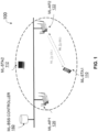
- FIG. 1 illustrates an example WLAN with infrastructure BSS configuration.
- the infrastructure BSS WLAN may include multiple ML stations (i.e., ML-STAs or non-AP ML devices), e.g., ML-STA1 110 and ML-STA2 112.
- a station may be in the coverage of a first ML access point (i.e. ML-AP or AP ML device), i.e., ML-AP1 120 and/or a second ML access point (i.e. ML-APs or AP ML devices), i.e., ML-AP2 122.
- a ML-AP1 120 can form an infrastructure ML-BSS1 and a ML-AP2 122 forms an infrastructure ML-BSS2.
- a ML-AP1 120 and a ML-AP2 122 may be interconnected via a switch through a distribution system (DS) to form a ML-BSS 100.
- a ML-AP1 120 and a ML-AP2 122 may be coordinated via a ML-BSS controller 150 for ML operation across multiple access points.
- a ML-STA (e.g., ML-STA1 110) with multiple radios can establish and operate multiple channels (or OFDMA sub-channels) in the same frequency band or different bands to communication with a ML-AP (e.g., ML-AP1 122).
- a ML-STA can associate with one or more ML-APs in the ML-BSS coverage to establish ML communication.
- a ML-AP 122 and a ML-STA 110 can leverage ML operation for a simultaneous transmission and reception (STR), a joint or a selective transmission over one or multiple radio frequency channels to reduce the access latency, improve the transmission reliability and/or increase the transmission throughput under the coordination of a ML-MBSS Controller 150.
- a ML communication may include bi-directional transmission between a ML-STA and a ML-AP through a part or all ML-links.
- a joint ML communication can refer to the operation that one or more ML devices (either non-AP ML devices or AP ML devices) transmit the same packet over MLs concurrently or receive the same packet over MLs concurrently.
- the ML device may combine the received signals in the baseband to improve the signal-to-noise-ratio (SINR) of received signals for increasing the reliability of transmissions or select the best signal from the multiple received signals in the MAC layer.
- SINR signal-to-noise-ratio
- a selective ML communication can refer to the operation that a ML device (either non-AP ML device or AP ML device) selectively transmits a packet over one or more MLs. It may be used by the ML-STA or ML-AP to reduce the access latency via selecting the first available link among ML.
- a simplex (i.e. non-simultaneous transmission and reception) ML communication can refer to the operation that a ML device (either non-AP ML device or AP ML device) can concurrently transmit packets over MLs, or concurrently receives packets over MLs, but cannot concurrently transmit and receive packets.
- a duplex (i.e. simultaneous transmission and reception) ML communication can refer to the operation that a ML device (either non-AP ML device or AP ML device) can concurrently transmit and receive packets over MLs.
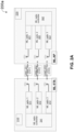
- FIGS. 2A-2B illustrate examples ML system architectures for ML station (i.e. non-AP ML device) and ML access point (i.e. AP ML device).
- the ML system 200a can include a ML-STA 210 and a ML-AP 220.
- a ML-STA 210 can include ML radios 211, 212 and 213.
- Each radio of ML-STA 210 may include an 802.11 PHY and a partial MAC (i.e., a lower MAC (MAC-L)).
- a ML radio 211 may operate on a wireless channel (CH1) to establish a radio link 251 to a ML-AP 220.
- a ML radio 212 and 213 may operate on wireless channels (CH3) respectively to establish radio link2 252 and link3 253 to a ML-AP 220.
- a ML-STA 210 may include a ML radio controller 241 which may consist of a common 802.11 MAC (i.e., upper MAC (MAC-U)) and a management entity which manages the ML operation of ML-STA 210.
- a ML radio controller 241 which may consist of a common 802.11 MAC (i.e., upper MAC (MAC-U)) and a management entity which manages the ML operation of ML-STA 210.
- MAC-U upper MAC
- the ML-AP 220 may include ML radios 221, 222 and 223. Each radio of ML-AP 220 may include an 802.11 PHY and a partial MAC (i.e., MAC-L). A radio 221 of ML-AP 220 may operate on a wireless channel (CH1) to establish a radio link 251 to the ML-STA 210. Similarly, ML radios 222 and 223 of ML-AP may operate on wireless channels (CH2 and CH3) respectively to establish radio link2 252 and link3 253 to ML-STA 210.
- the ML-AP 220 may have a ML radio controller 241 which may consist of a common 802.11 MAC (i.e. MAC-U) and a management entity for managing the ML operation of ML-AP 220.
- the ML system 200b may include a ML-STA 210, a ML-AP 220 and a ML-BSS controller 230.
- the ML-STA 210 can include ML radios 211, 212 and 213.
- Each radio of ML-STA 210 may include an 802.11 PHY and a partial MAC (i.e., MAC-L).
- a radio 211 may operate on a wireless channel (CH1) to establish a radio link1 231 to a ML-AP 220.
- ML radios 212 and 213 may operate on wireless channels (CH2 and CH3) respectively to establish radio link2 252 and link3 253 to a ML-AP 220.
- a ML-STA 210 may have a ML radio controller 241, which can consist of a common 802.11 MAC (MAC-U) and a management entity for managing the ML operation of ML-STA 210.
- MAC-U 802.11 MAC
- a ML-AP 220 may include ML radios 221, 222 and 223. Each radio of ML-AP 220 may include an 802.11 PHY and a partial MAC, i.e. MAC-L.
- a ML radio 221 may operate on a wireless channel (CH1) to establish a radio link 251 to the ML-STA 210.
- ML radios 222 and 223 may operate on wireless channels (CH2 and CH3) respectively to establish radio link2 252 and link3 253 to a ML-STA 210.
- the ML-BSS controller 230 which can be integrated with a ML-AP 220 or located separately as an individual network entity, may coordinate one or more ML radio controller 242 for ML operation.
- the ML 251, 252 and 253 may include wireless protocol links that can operate on radio channels in the same frequency band or different frequency bands, such as at a 2.4GHz, 5GHz, 6GHz band, etc.
- the links can have the same channel bandwidth, such as 20MHz, 40MHz, 80MHz, 160MHz, etc.
- the links may allow different channel bandwidth combinations, such as 160MHz + 160MHz + 20MHz, or 160MHz + 80MHz + 20MHz, etc.
- a ML-STA may associate with a ML-AP over any link to establish ML communication between them.
- a ML-STA and a ML-AP can exchange the ML capability information and determine the supported ML operation.
- a ML-STA may turn on a radio to listen to the transmissions in the unlicensed frequency band and search for Beacon frames.
- a ML-STA may turn on multiple ML-radios for fast searching over multiple channels simultaneously to reduce the searching time. If the ML-STA acquires a ML Beacon frame, the ML-STA may need to determine whether it can associate with this ML-AP.
- a ML device may set the user priority of traffic class in a MSDU during the traffic stream establishment. For example, when a high priority application needs to transmit a packet, it can specify its traffic type in a matter of DSCP to the QoS in the network-layer.
- the network-layer service can translate the QoS to a User Priority (UP) value and set it in the User Priority field of the Add Traffic Stream (ADDTS) request message.
- UP User Priority
- ADDTS Add Traffic Stream
- the user priority can then be mapped to one or more access categories of MPDU for channel access and scheduling a transmission. In this way, a high priority application can be mapped to a QoS packet in network-layer and is further mapped to an over-the-air user priority (i.e. access category) frame.
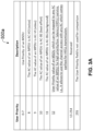
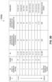
- FIGS. 3A-3D illustrate example tables 300a-d depicting user priority of traffic class for high priority and low latency MSDU and mapping to access categories of MPDU.
- a new user priority can be introduced for the high priority/low latency (HP/LL) service, which can allow for use of any AC which comes earliest in ML-CCA and transmit a data frame carrying the HP/LL MPDU.
- HP/LL high priority/low latency
- AC_ANY a virtual access category (AC), i.e., AC_ANY is introduced.
- AC_ANY can indicate that it can map to or use any AC, i.e., either AC_BK, AC_BE, AC_VI, or AC_VO for ML channel access. Therefore, it can allow for use of the AC with the earliest back off counter reaching to "0" in ML-CCA.
- an existing user priority UP-3 can be redefined and mapped to a virtual access category AC_ANY, i.e., allowing for use of an AC of the earliest back off counter reaching to "0" in ML-CCA and ML channel access.
- an existing user priority UP-3 can be redefined and mapped to a new access category AC_HP/LL for ML channel access. Therefore, the new access category AC_HP/LL can include a new access category of MPDU with the highest priority.
- a ML device may use a separate queue for AC_HP/LL from other ACs. The scheduler of a ML device may schedule a channel access for the AC_HP/LL prior to other ACs.
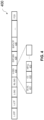
- FIG. 4 illustrates an example EHT frame format 400.
- An EHT frame can contain a legacy preamble portion, i.e., L-STF, L-LFT, L-SIG and RL-SIG with EHT portion, i.e., Universal Signal (U-SIG) 410, EHT-SIG 420, EHT-LTF 430, MPDU, and FCS.
- L-STF legacy preamble portion
- L-LFT L-LFT
- L-SIG L-SIG
- RL-SIG with EHT portion, i.e., Universal Signal (U-SIG) 410, EHT-SIG 420, EHT-LTF 430, MPDU, and FCS.
- U-SIG Universal Signal
- the legacy preamble can be used for a receiving station to detect a transmitted frame over the air interface.
- the repeated L-SIG i.e., RL-SIG
- the receiving station may combine L-SIG with RL-SIG to improve the received signal reliability.
- the U-SIG field 410 may contain a DL/UL indication field 411. This field can indicate this frame is a DL or UL transmission.
- the U-SIG field 410 may contain a CC field 412. This field can include a color code of the BSS. If the frame is for DL transmission, the ML-AP can set this field of frame to its color code associated to this link. If the frame is for UL transmission, the ML-STA can set this field of frame to the color code of this link assigned by the ML-AP.
- the U-SIG field 410 may contain a HP/LL field 413 This field can indicate that the frame carries a high priority/low latency MPDU.
- the ML transmitting device can set this field of frame to "1" if the data frame is carrying a HP/LL MPDU. Otherwise, this field can be set to "0.”
- Other ML devices which receive this frame but not being addressed by this frame may save the HP/LL field 413 associated to the NAV and use its value to decide whether this frame is pre-emptible or not during ML CCA and ML channel access if they need to transmit a HP/LL MSPU.
- a ML-CCA can include detecting any of L-STF, L-LTF, L-SIG, RL-SIG, and U-SIG.
- another way to indicate a HP/LL MPDU may be to carry this indication in an EHT-SIG or MAC header, e.g., in ETH control field, EHT variant field, etc.
- a ML device may use ML virtual carrier sensing and ML physical carrier sensing mechanism to assess the channel availability.
- a ML virtual carrier sensing can rely on the ML network allocation vector (NAV) to assess the channel availability.
- NAV ML network allocation vector
- a ML device detects a preamble and finds the transmission belongs an OBSS, it can set the ML-NAV associated to this channel to the occupancy with the period indicated by the duration field of received packet.
- the channel occupancy time can decrease as the time elapses. Once the ML-NAV value becomes to "0," this channel may become available for physical CCA and channel access.
- a ML device When a ML device detects an OBSS transmission carrying an EHT MPDU on a channel, it can mark in its corresponding ML-NAV for a HP/LL or non HP/LL frame based on the indication in U-SIG.
- a non-STR ML device When a non-STR ML device is transmitting a frame on one channel, it can mark in ML-NAVs of other channels as occupied for the period indicated by the duration field of transmitted packet.
- a ML-CCA can include a set of clear channel assessments, each of which can perform a physical carrier sensing on the corresponding channel.
- a CCA can be used to assess the channel availability by detecting a signal transmitted over this channel. Once a CCA of ML device detects the preamble signal strength beyond the preamble detection threshold (PDT) or the received signal strength beyond OBSS_PD, it can mark in ML-NAV the channel being occupied by In-BSS or Out-BSS for the period indicated by the duration field of received packet. Otherwise, the CCA of ML device can indicate the channel is idle and trigger EDCA back off procedure.
- PTT preamble detection threshold
- OBSS_PD the received signal strength beyond OBSS_PD
- a ML-CCA may support various back off procedures.
- a back off procedure can be for an independent ML-CCA.
- each link can have its own CCA for channel availability assessment and its own set of back off counters.
- Each back off counter can correspond to an access category, such as Background (AC_BK), Best Effort (AC_BE), Video (AC_VI) or Voice (AC_VO).
- a back off procedure can be for a joint ML-CCA.
- each link can have its own CCA for channel availability assessment but shares one set of back off counters.
- Each back off counter can correspond to an access category, such as Background (AC_BK), Best Effort (AC_BE), Video (AC_VI) or Voice (AC_VO).
- a ML device may choose an independent ML-CCA or a joint ML-CCA for channel assessment and access.
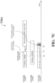
- FIG. 5 illustrates an example signal procedure of utilizing the ML radio to support high priority/low latency transmission over the wireless interface.
- FIG. 5 it can illustrate an example of supporting the high priority/low latency transmission via MLs.
- a ML device (either ML-STA or ML-AP) is instructed by the application via setting HP/LL of UP, it can be mapped to ANY AC of traffic class for transmitting a high priority/low latency MPDU.
- the ML device can perform the virtual carrier sensing via checking ML-NAVs on Link1 551 (CH1), Link2 552 (CH2) and Link3 553 (CH3).
- the ML device may simultaneously perform the physical ML-CCA sensing on those channels not being set by the ML-NAVs to find the earliest available channel(s) for the high priority/low latency transmission.
- the ML device may find the CH3 is the earliest available channel among the MLs if its ML back off counter corresponding to an access category reaches to 0 first and the ML-CCA can still detect the CH3 in idle. The ML device can then transmit a MPDU with HP/LL UP over the CH3.
- FIGS. 6A-6C illustrate example procedures of STR capable ML device using an independent ML-CCA on each link and a joint ML-CCA for support of high priority and low latency transmissions.
- a STR capable ML device can include three radios which operate on a radio channel 1 (CH1), a radio channel 2 (CH2) and a radio channel 3 (CH3) respectively to establish corresponding communication link 1 651, link 2 652 and link 3 653.
- CH1 radio channel 1
- CH2 radio channel 2
- CH3 radio channel 3
- a STR capable ML device can have multiple independent CCA, each of which is associated to a link and has its own set of CCA back off counters to corresponding ACs. All sets of CCA back off counters of all links can use the same set of EDCA parameters, like CW, CWmin, CWmax, etc. of ML device. However, each radio of ML device can use its own set of CCA back off counters, each of which is corresponding to an AC to count idle slots independently on its link. This can allow for each radio of ML device to sense its operating channel and perform channel access independently.
- a STR capable ML device can receive a pending HP/LL MPDU in its queue(s) at the time of T0.
- the ML device can defer its physical CCA until at least one of ML-NAVs becomes "0" at T1. If a radio of ML device performing CCA detects the channel in idle (e.g., CH2 or CH3), the CCA back off counters corresponding to ACs as shown in FIG. 3B for that link are reduced by "1.” If none of back off counter reaches to "0", the radio of ML device can continue a CCA process on its link (e.g.
- the ML device can begin to acquire a TXOP on this link (e.g., CH2 or CH3) via transmitting a control frame (e.g., ML-RTS, Trigger frame, etc.) or a data frame carrying the HP/LL MPDU.
- the ML device may transmit a same MPDU or different MPDU over CH2 and CH3 depending on the transmission requirement such as reliability or throughput.
- a STR capable ML device can include multiple independent CCA sensors, each of which can be associated to a link.
- the CCA sensors can share a set of joint ML CCA back off counters, each of which corresponds to an AC, such as described with respect to FIG. 3B .
- the joint ML-CCA back off counters corresponding to ACs can be reduced by "1.” If multiple channels (e.g., "N" channels) are sensed idle, the joint ML-CCA back off counters corresponding to ACs can be reduced by "N.” Accordingly, the joint ML-CCA can significantly reduce the waiting time on the idle channels and expedite the ML device to access to the earliest available channel to meet the high priority/low latency requirement.
- a STR capable ML device may obtain a pending HP/LL MPDU in its queue(s) at T0. As all channels, i.e., CH1, CH2, and CH3 are busy at T0 according to their ML-NAV values, the ML device can defer its physical CCA until at least one of ML-NAVs of corresponding links becomes "0" at T1. If any applicable radio of ML device performing CCA detects the channel in idle (e.g., CH2 and CH3), the joint ML-CCA back off counters corresponding to ACs can be reduced by "1."
- the ML device can start to acquire the TXOP on the idle link(s) (e.g. CH2 and CH3) via transmitting a control frame (such as ML-RTS) or a data frame carrying the HP/LL MPDU directly.
- a control frame such as ML-RTS
- the ML device may transmit a same MPDU or different MPDU over CH2 and CH3 depending on a transmission requirement, such as reliability or throughput.
- FIG. 6C it can illustrate the procedure of a joint ML-CCA and a channel access with preemption of a current OBSS transmission.
- a STR capable ML device can use a joint ML-CCA, which has multiple independent CCA sensors. Each CCA in the joint ML-CCA can be associated to links but share one set of back off counters for ACs.
- a STR capable ML device may obtain a pending HP/LL MPDU in its AC queue(s) at T0.
- all channels i.e., CH1, CH2, and CH3 may be busy according to their ML-NAV values.
- the CH1 may be occupied by OBSS traffic and the signal strength measurement may be over an Energy Detection (ED) threshold.
- the CH2 may be occupied by other OBSS traffic, but a signal strength measurement can be less than the OBSS Preamble Detection (OBSS_PD) threshold.
- PRE_IND Pre-emptible Indication
- the ML device detects PRE_IND during ML-NAV checking, it can ignore the ML-NAV setting on those channels and then can perform ML-CCA immediately at T1 with a higher ML-CCA detection threshold, e.g., the detection threshold for HP/LL transmission.
- a higher ML-CCA detection threshold e.g., the detection threshold for HP/LL transmission.
- the joint ML-CCA back off counters corresponding to ACs can be reduced by "1.”
- the joint ML-CCA back off counter of each AC can be reduced by "2," as both CH2 and CH3 are sensed as idle.
- the ML device can start to acquire the TXOP on the idle channel(s) (e.g., CH2 and CH3) via transmitting a control frame (such as ML-RTS, Trigger frame, etc.) or a data frame carrying the HP/LL MPDU.
- a control frame such as ML-RTS, Trigger frame, etc.
- the ML device may transmit a same MPDU or different MPDU over CH2 and CH3 depending on the transmission requirement such as reliability or throughput.
- FIGS. 7A - 7D illustrate example procedures of non-STR capable ML device using an independent ML-CCA on each link and a joint ML-CCA for support of high priority/low latency transmission.
- a STR capable ML device can include three radios which operate on a radio channel 1 (CH1), a radio channel 2 (CH2) and a radio channel 3 (CH3) respectively to establish corresponding communication link1 751, link2 752, and link3 753.
- CH1 radio channel 1
- CH2 radio channel 2
- CH3 radio channel 3
- FIG. 7A it can illustrate the ML-CCA and channel access procedure without interference to the current communication when the non-STR capable ML device is transmitting a frame.
- a non-STR capable ML device (either ML-STA or ML-AP) can include multiple independent ML-CCA sensors, each of which can be associated to a link and has its own set of back off counters for ACs, but all ML CCAs can use the same set of EDCA parameters (like CW, CWmin, CWmax, etc.) corresponding to the ACs.
- a non-STR capable ML device may use a joint ML-CCA mechanism which contains multiple independent CCA, each of which can be associated to a link but shares one set of back off counters for the ACs of the ML device.
- a non-STR ML device can receive from an application a HP/LL MSDU pending in a queue at the time T0. As all channels, i.e., CH1, CH2 and CH3, are busy at the time T0 according to their ML-NAV values, the ML device can defer its physical CCA until at least one of ML-NAVs is equal to "0" (e.g., link3 753). However, the non-STR capable ML device still may be unable to perform ML-CCA sensing on idle links (e.g., link3 753) due to the self-interference from the transmission over the link1 751.
- idle links e.g., link3 753
- ML-CCA can stop on any link and the back off counting, even if the link2 752 or link3 753 are idle after T0.
- the non-STR ML device When the non-STR ML device completes its transmission on the link1 751 at the time T1, it may resume ML-CCA and back off counting on other links (e.g., link2 752 and link3 753).
- the CCA back off counters corresponding to ACs can be reduced by "1" for the independent ML-CCA mechanism or by "2" for the joint ML-CCA mechanism if both CH2 and CH3 are detected idle, for example. If none of back off counter reaches to "0" after ML-CCA, the ML device can continue the ML-CCA process on the corresponding links (e.g., CH2 and/or CH3) until at least one of ML-CCA back off counters reaches to "0" or all links become busy.
- the ML device can start to acquire the TXOP on those links (e.g., CH2 and CH3) via transmitting a control frame (such as ML-RTS, Trigger frame, etc.) or a data frame carrying the HP/LL MPDU.
- a control frame such as ML-RTS, Trigger frame, etc.
- the ML device may transmit a same MPDU or different MPDU over CH2 and CH3 depending on the transmission requirement such as reliability or throughput.
- FIG. 7B it can illustrate the ML CCA and channel access procedure without interference to the current communication when the non-STR capable ML device is receiving a frame.
- a non-STR capable ML device can include multiple independent CCA sensors, each of which can be associated to a link and has its own set of back off counters for ACs, but all CCAs can use the same set of EDCA parameters (CW, CWmin, CWmax, etc.) corresponding to the ACs.
- a non-STR capable ML device may use a joint ML-CCA mechanism which contains multiple independent CCA, each of which can associated to a link.
- all CCAs share one set of back off counters for the ACs.
- a non-STR ML device can receive from an application a HP/LL MSDU pending in its queue at the time T0. As all channels, i.e., CH1, CH2, and CH3 are busy at the time T0 according to their ML-NAV values, the ML device may defer its physical CCA until at least one of ML-NAVs is equal to "0" (e.g., link3 753) at the time T1.
- "0" e.g., link3 753
- the non-STR capable ML device may perform ML-CCA (either the independent ML-CCA or the joint ML-CCA mechanism) on this un-occupied link (e.g., link2 752 or link3 753) during receiving a frame on other link(s) (e.g., link1 651).
- ML-CCA either the independent ML-CCA or the joint ML-CCA mechanism
- the non-STR ML device may be unable to perform channel access on the un-occupied link(s) as the transmitting signal of channel access will interfere to the ongoing communication on other link(s) (e.g., link1 751).
- the non-STR ML device may hold the channel access until the reception (e.g., on link1 751) completes. Once the reception on the link1 751 completes, the non-STR ML device may access to the media immediately after a SIFS at T2. This may reduce the channel access delay comparing to the ML CCA and channel access mechanism in FIG. 7A .
- the ML device may transmit a same MPDU or different MPDU over CH2 and CH3 depending on the transmission requirement such as reliability or throughput.
- FIG. 7C it can illustrate the ML-CCA and channel access procedure with preemption of the current non HP/LL communication to the non-STR capable ML device.
- a non-STR capable ML device may use an independent ML-CCA mechanism which has multiple independent CCA, each of which can be associated to a link and has its own individual set of back off counters for ACs, but all CCAs can use the same set of EDCA parameters (CW, CWmin, CWmax, etc.) corresponding to the ACs.
- independent ML-CCA mechanism which has multiple independent CCA, each of which can be associated to a link and has its own individual set of back off counters for ACs, but all CCAs can use the same set of EDCA parameters (CW, CWmin, CWmax, etc.) corresponding to the ACs.
- a non-STR capable ML device may use a joint ML-CCA mechanism which contains multiple independent CCA, each of which can be associated to a link but share one set of back off counters for the ACs.
- a non-STR ML device can receive from an application a HP/LL MSDU pending in its queue at the time T0. As all channels, i.e., CH1, CH2, and CH3 are busy at the time T0 according to their NAV values (> 0), the ML device can defer its physical CCA until at least one of ML-NAVs is equal to "0" (e.g., link3 653) at the time T1.
- the non-STR capable ML device can start ML-CCA (either the independent ML-CCA or the joint ML-CCA mechanism) on this un-occupied link (e.g., link3 753) at T1 during receiving a non HP/LL MPDU on another link (e.g., link1 751).
- ML-CCA either the independent ML-CCA or the joint ML-CCA mechanism
- the non-STR ML device can perform the channel access on the un-occupied channel (e.g., CH3) at T2 and preempts its current non HP/LL communication on another link (e.g., link1 751 on CH1).
- FIG. 7D it can illustrate the ML-CCA and channel access procedure with preemption of a current non HP/LL OBSS communication for the HP/LL transmission.
- a non-STR capable ML device may use an independent ML-CCA mechanism which has multiple independent CCA, each of which can be associated to a link and has its own individual set of back off counters for ACs, but all CCAs can use the same set of EDCA parameters (CW, CWmin, CWmax, etc.) corresponding to the ACs.
- independent ML-CCA mechanism which has multiple independent CCA, each of which can be associated to a link and has its own individual set of back off counters for ACs, but all CCAs can use the same set of EDCA parameters (CW, CWmin, CWmax, etc.) corresponding to the ACs.
- a non-STR capable ML device may use a joint ML-CCA mechanism that contains multiple independent CCA, each of which can be associated to a link but share one set of back off counters for the ACs.
- a non-STR ML device can receive from an application a HP/LL MSDU pending in its queue at the time T0. All channels, i.e., CH1, CH2, and CH3 are busy at the time T0 according to their ML-NAV values (> 0), but some channels can carry non HP/LL OBSS traffic (e.g., link3 753) or carrying an OBSS frame with signal strength measurement less that OBSS_PD (e.g., link1 751).
- the ML device can perform ML CCA with the detection threshold for HP/LL transmission on the channels carrying non HL-LL OBSS MPDU (e.g., CH3) or an OBSS frame with the signal strength measurement less than OBSS_PD (e.g., link1 751) at the time T1.
- non-STR ML device can perform the channel access on the link (e.g., link1 751 and/or link3 753) at the time T2 which may preempt the current OBSS communication on those links.
- the non-STR ML device may transmit a same MPDU or different MPDU over CH1 and CH3 depending on the transmission requirement such as reliability or throughput.
- the ML device may reduce the CW size and reset the back off counter to the CW. If the ML transmission fails, the ML device may double the CW size, reset the back off counter to the CW, and then perform the same ML-CCA for channel access to re-transmit the failed MPDU with the same sequence number.
- the present embodiments can relate to identifying a high priority/low latency data packet so that a multi-link device may schedule its transmission in a priority manner.
- the present embodiments can relate to identifying a high priority/low latency data packet includes a mapping it to any access category of traffic class so that the high priority/low latency data packet can be scheduled for transmission prior to other access category traffics.
- the present embodiments can relate to performing multi-link clear channel assessment to detect the earliest available channel(s) for transmission of high priority/low latency packet.
- the present embodiments can relate to performing a multi-link assessment includes utilizing a joint multi-link clear channel assessment mechanism to speed up the assessment procedure over multi-link significantly comparing to the existing clear channel assessment over one link.
- the present embodiments can relate to performing multi-link clear channel assessment over a channel carrying a pre-emptible communication and transmitting a high priority/low latency packet on this channel.
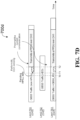
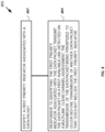
- FIG. 8 illustrates an example method 800 for utilizing the multi-link channel assessment mechanism and multi-link channel access to reduce the access delay, improve transmission reliability, and increase transmission throughput.
- a method for wireless communication can include identifying, by a radio node, a first priority indicator associated with a data packet (block 802).
- the radio node can include a multi-link station (e.g., ML-STA 1 110) as described herein.
- the first priority indicator can include an indicator indicative of a high priority and low latency service as described herein.
- the method can also include, responsive to identifying the first priority indicator associated with the data packet, transmitting, by the radio node, the data packet on a first available link detected via a multi-link clear channel assessment, the transmission of the data packet being prioritized to occur before transmission of another data packet that does not include the first priority indicator (block 804).
- the multi-link clear channel assessment includes inspecting, by the radio node, a multi-link network allocation vector (ML-NAV) value for each link of the multiple links to determine whether the first available link is available for transmission of the data packet, and responsive to determining that the first available link is available for transmission of the data packet, initiating, by the radio node, a back off counter for the first available link, wherein the data packet is transmitted responsive to determining that the back off counter has expired.
- ML-NAV multi-link network allocation vector
- the first priority indicator is associated with a user priority associated with a first priority service.
- the first priority service can include the high priority and low latency service as described herein.
- the first priority service allows the radio node to utilize any access category virtually with an earliest availability via a multi-link assessment, wherein the data packet includes a data frame including a high priority and low latency media access control (MAC) protocol data unit (MPDU).
- MAC media access control
- the user priority associated with the first priority service includes a user priority value of 12.
- the user priority associated with the first priority service includes a user priority value of 3 that corresponds to a virtual access category relating to any channel access or a high priority channel access.
- the method includes mapping, by the radio node, the user priority associated with the first priority service to a corresponding first access category for multi-link channel access.
- the method includes obtaining, by the radio node, an extremely high throughput (EHT) message that includes the first priority indicator, wherein the first priority indicator is included within a universal signal portion of the EHT message.
- EHT extremely high throughput
- the method includes, for each link of the multiple links of the radio node, determining, by the radio node, that a first link is in an idle state, responsive to determining that the first link is in to the idle state, starting, by the radio node, a back off counter associated with an access category relating to the first priority indicator, and responsive to determining that the back off counter has expired, transmitting, by the radio node, the data packet over the first link, the data packet including a MAC protocol data unit (MPDU) with the user priority associated with the first priority service.
- MPDU MAC protocol data unit
- determining that the first link is in the idle state includes performing a clear channel assessment of the multiple links of the radio node.
- the method includes receiving, by the radio node, a first message that includes the first priority indicator at a first time, determining, by the radio node, that a first link and a second link is in an idle state at a second time, starting, by the radio node, an independent back off counter for each of the first link and second link responsive to determining that each of the first link and the second link is in the idle state, and responsive to each independent back off counter expiring, transmitting, by the radio node, at least a portion of the data packet over each of the first link and second link.
- Starting the independent back off counter for each of the first link and second link can include any of initializing the back off counter or resuming an existing back off counter.
- the method includes receiving, by the radio node, a first message that includes the first priority indicator at a first time, determining, by the radio node, that a first link and a second link is in an idle state at a second time, starting, by the radio node, a back off counter common to each of the first link and second link responsive to determining that each of the first link and the second link is in the idle state, and responsive to determining that the back off counter has expired, transmitting, by the radio node, at least a portion of the data packet over each of the first link and second link.
- the method includes receiving, by the radio node, a first message that includes the first priority indicator at a first time, determining, by the radio node, whether each link of the multiple links includes a signal strength measurement that is less than an overlapping basis service set preamble detection threshold, responsive to determining that each of a first link and a second link of the multiple links includes signal strength measurements that are less than the overlapping basis service set preamble detection threshold, starting, by the radio node, a back off counter common to each of the first link and second link, and responsive to determining that the back off counter has expired, transmitting, by the radio node, at least a portion of the data packet over each of the first link and second link, wherein any other communication over the first link and second link are preempted by the data packet.
- said transmitting at least the portion of the data packet over each of the first link and second link includes transmitting the data packet with a signal strength that is greater than a signal strength of overlapping basic service set (OBSS) data transmitted over the first link and second link.
- OBSS overlapping basic service set
- the method includes receiving, by the radio node, a first message that includes the first priority indicator at a first time, determining, by the radio node, that all links of the multiple links are in an idle state at a second time, wherein a clear channel assessment of the multiple links is not performed until determining that all links of the multiple links are in the idle state at the second time, starting, by the radio node, an individual back off counter for each of the first link and second link, and responsive to determining that the individual back off counters have expired at a third time, transmitting, by the radio node, at least a portion of the data packet over each of the first link and second link.
- the method includes receiving, by the radio node, a first message that includes the first priority indicator at a first time, determining, by the radio node, that a first link is in an idle state at a second time, starting, by the radio node, a first back off counter for the first link, determining, by the radio node, that a first link is still in the idle state at third time, starting, by the radio node, a second back off counter for the second link, and responsive to expiry of the first back off counter and the second back off counter and determining that all links are in the idle state at a fourth time, transmitting, by the radio node, at least a portion of the data packet over each of the first link and second link.
- the method includes receiving, by the radio node, a first message that includes the first priority indicator at a first time, determining, by the radio node, that a first link is in an idle state at a second time, starting, by the radio node, a first back off counter for the first link, transmitting, by the radio node, the data packet over the first link, wherein the transmission of the data packet over the first link preempts a transmission over a second link.
- the method includes receiving, by the radio node, a first message that includes the first priority indicator at a first time, determining, by the radio node, that a first link of the multiple links includes a signal strength measurement that is less than an overlapping basis service set preamble detection threshold and that a third link is greater than the overlapping basis service set preamble detection threshold, determining, by the radio node, that a second link includes data traffic that does not include any high priority low latency indicators, starting, by the radio node, a first back off counter for the first link and a second back off counter for the second link, and responsive to determining that the first and second back off counters
- said transmitting at least the portion of the data packet over each of the first link and second link includes transmitting the data packet with a signal strength that is greater than a signal strength of OBSS data transmitted over the first link and second link.
- FIG. 9 is a block diagram representation of a portion of a hardware platform.
- a hardware platform 905 such as a network device or a base station or a wireless device (or UE) can include processor electronics 910 such as a microprocessor that implements one or more of the techniques presented in this document.
- the hardware platform 905 can include transceiver electronics 915 to send and/or receive wired or wireless signals over one or more communication interfaces such as antenna 920 or a wireline interface.
- the hardware platform 905 can implement other communication interfaces with defined protocols for transmitting and receiving data.
- the hardware platform 905 can include one or more memories (not explicitly shown) configured to store information such as data and/or instructions.
- the processor electronics 910 can include at least a portion of the transceiver electronics 915. In some embodiments, at least some of the disclosed techniques, modules or functions are implemented using the hardware platform 905.
- the disclosed and other embodiments, modules and the functional operations described in this document can be implemented in digital electronic circuitry, or in computer software, firmware, or hardware, including the structures disclosed in this document, or in combinations of one or more of them.
- the disclosed and other embodiments can be implemented as one or more computer program products, i.e., one or more modules of computer program instructions encoded on a computer readable medium for execution by, or to control the operation of, data processing apparatus.
- the computer readable medium can be a machine-readable storage device, a machine-readable storage substrate, a memory device, a composition of matter effecting a machine-readable propagated signal, or a combination of one or more them.
- data processing apparatus encompasses all apparatus, devices, and machines for processing data, including by way of example a programmable processor, a computer, or multiple processors or computers.
- the apparatus can include, in addition to hardware, code that creates an execution environment for the computer program in question, e.g., code that constitutes processor firmware, a protocol stack, a database management system, an operating system, or a combination of one or more of them.
- a propagated signal is an artificially generated signal, e.g., a machine-generated electrical, optical, or electromagnetic signal, that is generated to encode information for transmission to suitable receiver apparatus.
- a computer program (also known as a program, software, software application, script, or code) can be written in any form of programming language, including compiled or interpreted languages, and it can be deployed in any form, including as a stand-alone program or as a module, component, subroutine, or other unit suitable for use in a computing environment.
- a computer program does not necessarily correspond to a file in a file system.
- a program can be stored in a portion of a file that holds other programs or data (e.g., one or more scripts stored in a markup language document), in a single file dedicated to the program in question, or in multiple coordinated files (e.g., files that store one or more modules, sub programs, or portions of code).
- a computer program can be deployed to be executed on one computer or on multiple computers that are located at one site or distributed across multiple sites and interconnected by a communication network.
- the processes and logic flows described in this document can be performed by one or more programmable processors executing one or more computer programs to perform functions by operating on input data and generating output.
- the processes and logic flows can also be performed by, and apparatus can also be implemented as, special purpose logic circuitry, e.g., an FPGA (field programmable gate array) or an ASIC (application specific integrated circuit).
- Computer readable media suitable for storing computer program instructions and data include all forms of non-volatile memory, media and memory devices, including by way of example semiconductor memory devices, e.g., EPROM, EEPROM, and flash memory devices; magnetic disks, e.g., internal hard disks or removable disks; magneto optical disks; and CD ROM and DVD-ROM disks.
- semiconductor memory devices e.g., EPROM, EEPROM, and flash memory devices
- magnetic disks e.g., internal hard disks or removable disks
- magneto optical disks e.g., CD ROM and DVD-ROM disks.
- the processor and the memory can be supplemented by, or incorporated in, special purpose logic circuitry.
Landscapes
- Engineering & Computer Science (AREA)
- Computer Networks & Wireless Communication (AREA)
- Signal Processing (AREA)
- Mobile Radio Communication Systems (AREA)
Claims (8)
- Verfahren zur drahtlosen Kommunikation, das aufweist:Empfangen, durch einen Funkknoten, einer ersten Nachricht, die einen ersten Prioritätsindikator aufweist, der einen Dienst mit hoher Priorität/geringer Latenz, HP/LL, anzeigt, zu einem ersten Zeitpunkt;Identifizieren (802), durch den Funkknoten (110-120), des ersten Prioritätsindikators, der mit einem Datenpaket assoziiert ist; undals Reaktion auf das Identifizieren des ersten Prioritätsindikators, der mit dem Datenpaket assoziiert ist, Senden (804), durch den Funkknoten (110-120), des Datenpakets über eine erste Verbindung und eine zweite Verbindung, die über eine Mehrfachverbindung-Freikanal-Bewertung erkannt wurden, wobei die Übertragung des Datenpakets so priorisiert wird, dass sie vor der Übertragung eines anderen Datenpakets erfolgt, das nicht den ersten Prioritätsindikator aufweist, wobei die Übertragung des Datenpakets umfasst:Bestimmen, durch den Funkknoten, ob jede Verbindung der mehreren Verbindungen eine Signalstärkemessung aufweist, die kleiner ist als ein Schwellenwert für die Erkennung der Präambel eines überlappenden Basisdienstsatzes;als Reaktion auf die Bestimmung, dass jede der ersten Verbindung und der zweiten Verbindung der mehreren Verbindungen Signalstärkemessungen aufweist, die kleiner sind als der Schwellenwert für die Erkennung der Präambel eines überlappenden Basisdienstsatzes, Starten, durch den Funkknoten, eines Rückstellzählers, der jeder der ersten Verbindung und der zweiten Verbindung gemeinsam ist; undals Reaktion auf die Feststellung, dass der Rückstellzähler abgelaufen ist, Senden, durch den Funkknoten, mindestens eines Anteils des Datenpakets über jede der ersten und zweiten Verbindung, wobei jede andere Kommunikation über die erste und zweite Verbindung durch das Datenpaket ausgeschlossen wird.
- Verfahren nach Anspruch 1, wobei der erste Prioritätsindikator mit einer Benutzerpriorität verbunden ist, die mit einem Dienst erster Priorität assoziiert ist, und wobei der Dienst mit erster Priorität es dem Funkknoten (110-120) ermöglicht, jede Zugangskategorie virtuell mit einer frühesten Verfügbarkeit über eine Mehrverbindungsbewertung zu nutzen, wobei das Datenpaket einen Datenrahmen aufweist, der eine Medienzugriffssteuerung, MAC, Protokolldateneinheit, MPDU mit hoher Priorität und geringer Latenz aufweist.
- Verfahren nach Anspruch 1, das ferner aufweist:
Erhalten, durch den Funkknoten (110-120), einer Nachricht mit extrem hoher Durchsatzrate, EHT, die den ersten Prioritätsindikator enthält, wobei der erste Prioritätsindikator in einem universellen Signalabschnitt der EHT-Nachricht enthalten ist. - Verfahren nach Anspruch 1 oder 2, das ferner aufweist:für jede Verbindung der mehreren Verbindungen des Funkknotens (110-120) Bestimmen, durch den Funkknoten (110-120), dass sich eine erste Verbindung in einem Leerlaufzustand befindet;als Reaktion auf die Bestimmung, dass sich die erste Verbindung im Leerlaufzustand befindet, Starten, durch den Funkknoten (110-120), eines Rückstellzählers, der mit einer Zugriffskategorie assoziiert ist, die sich auf den ersten Prioritätsindikator bezieht; undals Reaktion auf die Feststellung, dass der Rückstellzähler abgelaufen ist, Senden, durch den Funkknoten (110-120), des Datenpakets über die erste Verbindung, wobei das Datenpaket eine MAC-Protokoll-Dateneinheit, MPDU, mit der Benutzerpriorität aufweist, die mit dem Dienst mit der ersten Priorität assoziiert ist.
- Verfahren nach Anspruch 1, das ferner aufweist:Bestimmen, durch den Funkknoten (110-120), dass sich die erste Verbindung und die zweite Verbindung zu einem zweiten Zeitpunkt in einem Leerlaufzustand befinden;Starten, durch den Funkknoten (110-120), eines unabhängigen Rückstellzählers für jede der ersten Verbindung und der zweiten Verbindung als Reaktion auf die Bestimmung, dass sich jede der ersten Verbindung und der zweiten Verbindung im Leerlaufzustand befindet; undals Reaktion auf das Ablaufen jedes unabhängigen Rückstellzählers, Senden, durch den Funkknoten (110-120), mindestens eines Anteils des Datenpakets über jede der ersten Verbindung und der zweiten Verbindung.
- Verfahren nach Anspruch 1, das ferner aufweist:Bestimmen, durch den Funkknoten (110-120), dass die erste Verbindung der mehreren Verbindungen eine Signalstärkemessung aufweist, die kleiner ist als ein Schwellenwert für die Erkennung der Präambel eines überlappenden Basisdienstsatzes und dass eine dritte Verbindung eine Signalstärkemessung aufweist, die größer ist als der Schwellenwert für die Erkennung der Präambel eines überlappenden Basisdienstsatzes;Bestimmen, durch den Funkknoten (110-120), dass die zweite Verbindung Datenverkehr enthält, der keine Indikatoren für hohe Priorität und niedrige Latenz aufweist;Starten, durch den Funkknoten (110-120), eines ersten Rückstellzählers für die erste Verbindung und eines zweiten Rückstellzählers für die zweite Verbindung; undals Reaktion auf die Feststellung, dass der erste und der zweite Rückstellzähler abgelaufen sind, Senden, durch den Funkknoten (110-120), mindestens eines Anteils des Datenpakets über die erste Verbindung und die zweite Verbindung.
- Vorrichtung zur drahtlosen Kommunikation, die einen Prozessor aufweist, der konfiguriert ist, einen Funkknoten zu veranlassen, das Verfahren nach einem der Ansprüche 1 bis 6 auszuführen.
- Nichtflüchtiges, computerlesbares Medium mit darauf gespeichertem Code, wobei der Code, wenn er von einem Prozessor eines Funkknotens ausgeführt wird, den Funkknoten veranlasst, ein Verfahren nach einem der Ansprüche 1 bis 6 zu implementieren.
Applications Claiming Priority (2)
| Application Number | Priority Date | Filing Date | Title |
|---|---|---|---|
| PCT/CN2019/095428 WO2021003700A1 (en) | 2019-07-10 | 2019-07-10 | Multi-link communications of a wireless network |
| PCT/CN2020/078991 WO2021004079A1 (en) | 2019-07-10 | 2020-03-12 | Multi-link wireless communication networks for high priority/low latency services |
Publications (3)
| Publication Number | Publication Date |
|---|---|
| EP3997940A1 EP3997940A1 (de) | 2022-05-18 |
| EP3997940A4 EP3997940A4 (de) | 2022-10-26 |
| EP3997940B1 true EP3997940B1 (de) | 2025-06-11 |
Family
ID=74113814
Family Applications (2)
| Application Number | Title | Priority Date | Filing Date |
|---|---|---|---|
| EP20837346.4A Active EP3997940B1 (de) | 2019-07-10 | 2020-03-12 | Mehrstrecken-drahtloskommunikationsnetzwerke für dienste mit hoher priorität/niedriger latenz |
| EP20836839.9A Active EP3997930B1 (de) | 2019-07-10 | 2020-05-06 | Einstellbare multilink-freikanalbeurteilung für drahtlose kommunikationsnetzwerke |
Family Applications After (1)
| Application Number | Title | Priority Date | Filing Date |
|---|---|---|---|
| EP20836839.9A Active EP3997930B1 (de) | 2019-07-10 | 2020-05-06 | Einstellbare multilink-freikanalbeurteilung für drahtlose kommunikationsnetzwerke |
Country Status (4)
| Country | Link |
|---|---|
| US (1) | US12108465B2 (de) |
| EP (2) | EP3997940B1 (de) |
| CN (2) | CN114097291B (de) |
| WO (1) | WO2021004142A1 (de) |
Families Citing this family (24)
| Publication number | Priority date | Publication date | Assignee | Title |
|---|---|---|---|---|
| WO2021003700A1 (en) | 2019-07-10 | 2021-01-14 | Zte Corporation | Multi-link communications of a wireless network |
| US11889435B2 (en) * | 2019-07-12 | 2024-01-30 | Mediatek Singapore Pte. Ltd. | Enhanced high-throughput synchronous and constrained multi-link transmissions in WLAN |
| US11665574B2 (en) * | 2019-10-25 | 2023-05-30 | Qualcomm Incorporated | Physical layer preamble design for special packet types |
| CN119584256A (zh) * | 2019-11-08 | 2025-03-07 | 华为技术有限公司 | 一种多链路设备间的通信方法和装置 |
| JP7347653B2 (ja) * | 2020-03-17 | 2023-09-20 | 日本電信電話株式会社 | 端末、通信方法及び通信プログラム |
| CN116744468B (zh) * | 2020-06-18 | 2024-04-26 | 华为技术有限公司 | 多链路设备的信道接入方法及相关装置 |
| US12232160B2 (en) * | 2020-12-02 | 2025-02-18 | Intel Corporation | Preemption mechanism for WLAN |
| US12362873B2 (en) * | 2021-03-11 | 2025-07-15 | Mediatek Singapore Pte. Ltd. | Enhanced multi-link operation switching mechanisms |
| JP7682663B2 (ja) * | 2021-03-26 | 2025-05-26 | キヤノン株式会社 | 通信装置、通信方法、およびプログラム |
| US11683835B2 (en) * | 2021-04-02 | 2023-06-20 | Hewlett Packard Enterprise Development Lp | Spatial reuse for high priority traffic |
| US11889559B2 (en) * | 2021-04-06 | 2024-01-30 | Qualcomm Incorporated | Channel sensing with self-interference awareness for unlicensed band |
| WO2023050346A1 (zh) * | 2021-09-30 | 2023-04-06 | Oppo广东移动通信有限公司 | 能量检测门限的确定方法、装置、设备及存储介质 |
| US12348305B2 (en) * | 2021-11-14 | 2025-07-01 | Microsoft Technology Licensing, Llc | Multidimensional service differentiation for WiFi traffic |
| CN116321178B (zh) * | 2021-12-20 | 2026-03-17 | 华为技术有限公司 | 一种空闲信道评估阈值的确定方法及装置 |
| EP4486017A4 (de) * | 2022-03-23 | 2025-06-18 | Huawei Technologies Co., Ltd. | Kommunikationsverfahren und -vorrichtung |
| US12426086B2 (en) * | 2022-09-24 | 2025-09-23 | Qualcomm Incorporated | Flexible multi-link operation architecture |
| CN115720360A (zh) * | 2022-11-10 | 2023-02-28 | 宜宾市极米光电有限公司 | 省电模式操作方法、装置、设备及存储介质 |
| US20240163947A1 (en) * | 2022-11-10 | 2024-05-16 | Mediatek Inc. | Method and apparatus for multi-link operation |
| US20240163932A1 (en) * | 2022-11-10 | 2024-05-16 | Mediatek Inc. | Multi-link operation (mlo) transmission method and apparatus thereof |
| CN115835282A (zh) * | 2022-11-29 | 2023-03-21 | 深圳市共进电子股份有限公司 | 一种无线网络性能的测试方法、装置及网络系统 |
| CN116017646A (zh) * | 2022-12-15 | 2023-04-25 | 宜宾市极米光电有限公司 | 多链路终端设备的唤醒方法、终端设备、接入设备和存储介质 |
| US20240381417A1 (en) * | 2023-05-12 | 2024-11-14 | Qualcomm Incorporated | Techniques for multi-primary channel access |
| WO2025005484A1 (ko) * | 2023-06-28 | 2025-01-02 | 엘지전자 주식회사 | 무선랜 시스템에서 채널 액세스 절차를 수행하는 방법 및 장치 |
| CN120653182A (zh) * | 2024-03-14 | 2025-09-16 | 华为技术有限公司 | 存储系统、处理器系统、访问方法和芯片系统 |
Family Cites Families (46)
| Publication number | Priority date | Publication date | Assignee | Title |
|---|---|---|---|---|
| JPH09289684A (ja) | 1996-04-23 | 1997-11-04 | Matsushita Electric Ind Co Ltd | 無線通信システム |
| US20050152373A1 (en) * | 2004-01-08 | 2005-07-14 | Interdigital Technology Corporation | Packet scheduling in a wireless local area network |
| US8909945B2 (en) * | 2005-04-08 | 2014-12-09 | Interdigital Technology Corporation | Method for transmit and receive power control in mesh systems |
| US9124460B2 (en) | 2010-08-31 | 2015-09-01 | Qualcomm, Incorporated | Rules for multiplexing data of different access categories in multi user MIMO wireless systems |
| TWI526020B (zh) | 2010-11-16 | 2016-03-11 | 內數位專利控股公司 | 無線直接鏈結操作方法及裝置 |
| CN104349405B (zh) | 2013-07-23 | 2019-01-08 | 华为技术有限公司 | 传输数据的方法、通信节点和基站 |
| US9345047B2 (en) | 2013-10-04 | 2016-05-17 | Qualcomm Incorporated | Techniques for assessing clear channel in an unlicensed radio frequency spectrum band |
| EP3072247A4 (de) * | 2013-11-19 | 2017-08-23 | Intel IP Corporation | Framestruktur mit reduziertem signalfeld und verfahren für hocheffiziente wifi (hew)-kommunikation |
| US11297510B2 (en) * | 2015-01-19 | 2022-04-05 | Qualcomm Incorporated | Medium access for shared or unlicensed spectrum |
| US10142985B2 (en) * | 2015-04-21 | 2018-11-27 | Apple Inc. | Opportunistic secondary channel access |
| US10142972B2 (en) * | 2015-04-27 | 2018-11-27 | Qualcomm Incorporated | Methods and apparatus for multiple user uplink response rules |
| US9942843B2 (en) | 2015-07-01 | 2018-04-10 | Intel IP Corporation | Determining a network allocation vector setting and a response to a multi-user transmission opportunity |
| US10772127B2 (en) * | 2015-07-10 | 2020-09-08 | Lg Electronics Inc. | Method and device for transmitting data burst in wireless access system supporting unlicensed band and carrier aggregation |
| US10531488B2 (en) * | 2015-08-11 | 2020-01-07 | Lg Electronics Inc. | Method for transmitting/receiving wireless signal in wireless communication system and device therefor |
| US10638516B2 (en) | 2015-08-19 | 2020-04-28 | Zte Corporation | Controlling transmissions from multiple user devices via a request-clear technique |
| US10285203B2 (en) | 2015-08-26 | 2019-05-07 | Newracom, Inc. | Network allocation vector types and transmission opportunity types for spatial reuse |
| WO2017111185A1 (ko) * | 2015-12-22 | 2017-06-29 | 엘지전자(주) | 무선통신 시스템에서 데이터를 송수신하기 위한 방법 및 장치 |
| US10194468B2 (en) * | 2016-03-04 | 2019-01-29 | Apple Inc. | Wireless channel reservation |
| CN106375045B (zh) * | 2016-09-08 | 2019-01-29 | 北京交通大学 | 一种高速铁路场景下多链路信道探测系统与方法 |
| US10420120B2 (en) * | 2016-12-15 | 2019-09-17 | Lg Electronics Inc. | Method for transmitting uplink frame in wireless LAN system and wireless device using the same |
| US20180176954A1 (en) * | 2016-12-15 | 2018-06-21 | Intel Corporation | Clear channel assessment for simultaneous transmision and reception |
| CN108617029B (zh) | 2016-12-30 | 2023-05-12 | 夏普株式会社 | 无线承载配置方法、及相应的ue和基站 |
| GB2558620B (en) * | 2017-01-10 | 2019-10-02 | Canon Kk | Communication methods, communication device station and access point |
| WO2018136513A1 (en) | 2017-01-17 | 2018-07-26 | Dana Automotive Systems Group, Llc | Ported wheel hub assembly and the tire inflation system made therewith |
| US10856203B2 (en) | 2017-01-19 | 2020-12-01 | Qualcomm Incorporated | Signaling for link aggregation setup and reconfiguration |
| US11337263B2 (en) * | 2017-01-19 | 2022-05-17 | Qualcomm Incorporated | Packet based link aggregation architectures |
| US11304037B2 (en) | 2017-06-30 | 2022-04-12 | Intel Corporation | V2X communications using multiple radio access technologies (multi-RAT) |
| US10959153B2 (en) | 2017-09-11 | 2021-03-23 | Qualcomm Incorporated | Techniques for multi-link aggregation signaling |
| US10820346B2 (en) * | 2017-09-11 | 2020-10-27 | Qualcomm Incorporated | Clear channel assessment adjustment for in-band link aggregation |
| US20190116546A1 (en) | 2017-10-17 | 2019-04-18 | Electronics And Telecommunications Research Institute | Method for notifying downlink data in a network, network triggered service request method, and network entity performing the same |
| US11032207B2 (en) * | 2017-11-17 | 2021-06-08 | Qualcomm Incorporated | Link aggregation with floating primary link |
| WO2019112726A1 (en) * | 2017-12-08 | 2019-06-13 | Marvell World Trade Ltd. | Wifi operation with channel aggregation |
| US11357046B2 (en) * | 2017-12-29 | 2022-06-07 | Lg Electronics Inc. | Method and apparatus for controlling signal transmission of terminal supporting plurality of carriers |
| JP7366906B2 (ja) | 2018-01-11 | 2023-10-23 | パナソニック インテレクチュアル プロパティ コーポレーション オブ アメリカ | 低電力マルチユーザ送信のための通信装置および通信方法 |
| US10925065B2 (en) * | 2018-06-15 | 2021-02-16 | Intel Corporation | Extreme high throughput physical layer data rate |
| US11202286B2 (en) | 2018-07-11 | 2021-12-14 | Intel Corporation | Methods for multi-link setup between a multi-link access point (AP) logical entity and a multi-link non-AP logical entity |
| US12082192B2 (en) * | 2018-08-07 | 2024-09-03 | Interdigital Patent Holdings, Inc. | NR V2X—methods for data transmission in wireless systems |
| SG10201807626YA (en) | 2018-09-05 | 2020-04-29 | Panasonic Ip Corp America | Communication apparatus and communication method for multi-band operation |
| WO2020080989A1 (en) | 2018-10-19 | 2020-04-23 | Telefonaktiebolaget Lm Ericsson (Publ) | Handling of machine learning to improve performance of a wireless communications network |
| SG10201809503RA (en) | 2018-10-26 | 2020-05-28 | Panasonic Ip Corp America | Communication Apparatus And Communication Method For Multi-Band Transmission |
| CN109587052B (zh) * | 2019-01-30 | 2022-03-15 | 展讯通信(上海)有限公司 | 一种多链路数据传输方法及装置 |
| CN112003684A (zh) | 2019-05-27 | 2020-11-27 | 华为技术有限公司 | 数据传输方法及装置 |
| US11510269B2 (en) | 2019-07-01 | 2022-11-22 | Qualcomm Incorporated | Signaling for multi-link communication in a wireless local area network (WLAN) |
| CN112188640B (zh) | 2019-07-05 | 2024-11-01 | 华为技术有限公司 | 通信保护方法及装置 |
| KR102696185B1 (ko) | 2020-03-11 | 2024-08-20 | 주식회사 윌러스표준기술연구소 | 멀티 링크를 사용하는 무선 통신 방법 및 이를 사용하는 무선 통신 단말 |
| WO2022164293A1 (ko) | 2021-02-01 | 2022-08-04 | 주식회사 윌러스표준기술연구소 | 멀티 링크를 사용하는 무선 통신 방법 및 이를 사용하는 무선 통신 단말 |
-
2020
- 2020-03-12 EP EP20837346.4A patent/EP3997940B1/de active Active
- 2020-03-12 CN CN202080050271.1A patent/CN114097291B/zh active Active
- 2020-05-06 EP EP20836839.9A patent/EP3997930B1/de active Active
- 2020-05-06 CN CN202080050327.3A patent/CN114128369B/zh active Active
- 2020-05-06 WO PCT/CN2020/088757 patent/WO2021004142A1/en not_active Ceased
-
2022
- 2022-01-10 US US17/647,567 patent/US12108465B2/en active Active
Also Published As
| Publication number | Publication date |
|---|---|
| EP3997940A4 (de) | 2022-10-26 |
| EP3997930B1 (de) | 2025-08-20 |
| EP3997940A1 (de) | 2022-05-18 |
| US12108465B2 (en) | 2024-10-01 |
| EP3997930A1 (de) | 2022-05-18 |
| US20220159718A1 (en) | 2022-05-19 |
| CN114128369A (zh) | 2022-03-01 |
| EP3997930A4 (de) | 2022-10-26 |
| CN114097291B (zh) | 2025-03-28 |
| CN114097291A (zh) | 2022-02-25 |
| CN114128369B (zh) | 2025-08-05 |
| WO2021004142A1 (en) | 2021-01-14 |
Similar Documents
| Publication | Publication Date | Title |
|---|---|---|
| EP3997940B1 (de) | Mehrstrecken-drahtloskommunikationsnetzwerke für dienste mit hoher priorität/niedriger latenz | |
| WO2021004079A1 (en) | Multi-link wireless communication networks for high priority/low latency services | |
| US12267881B2 (en) | Frame transmission method and device using multiple random backoff operation in broadband wireless communication network | |
| US12108444B2 (en) | Adjustable multi-link clear channel assessment for wireless communication networks | |
| KR101612680B1 (ko) | 무선랜에서 채널 액세스 방법 및 장치 | |
| US7843819B1 (en) | Protocol for wireless multi-channel access control | |
| KR101585823B1 (ko) | 무선랜에서 초기 액세스 분산 방법 및 장치 | |
| CN103037531B (zh) | 一种无线站点接入信道的方法及系统 | |
| KR20220030278A (ko) | 멀티-링크 통신 방법 및 장치 | |
| US12538351B2 (en) | Method and device for transmitting frame through determination of channel expansion in broadband wireless communication network | |
| US10128988B2 (en) | Method and apparatus for reporting information about transmission failure frame | |
| WO2015194727A1 (ko) | 프레임을 전송하는 방법 및 장치 | |
| KR20150045429A (ko) | 무선랜에서 채널 액세스 방법 및 장치 | |
| KR20150020284A (ko) | 무선랜에서 초기 액세스 방법 및 장치 | |
| US12114374B2 (en) | Method and device for transmitting frame through extended channel in broadband wireless communication network | |
| US11082887B2 (en) | Method for retransmitting frame in wireless LAN system, and wireless terminal using same | |
| US10743348B2 (en) | Method for multi-user transmission in wireless LAN system and wireless terminal using same | |
| JP2026047555A (ja) | 端末装置、基地局装置および通信方法 | |
| WO2025234487A1 (ja) | 端末装置、基地局装置および通信方法 | |
| JP2026044332A (ja) | 基地局装置、端末装置および通信方法 | |
| WO2026029089A1 (ja) | 端末装置、基地局装置および通信方法 |
Legal Events
| Date | Code | Title | Description |
|---|---|---|---|
| STAA | Information on the status of an ep patent application or granted ep patent |
Free format text: STATUS: THE INTERNATIONAL PUBLICATION HAS BEEN MADE |
|
| PUAI | Public reference made under article 153(3) epc to a published international application that has entered the european phase |
Free format text: ORIGINAL CODE: 0009012 |
|
| STAA | Information on the status of an ep patent application or granted ep patent |
Free format text: STATUS: REQUEST FOR EXAMINATION WAS MADE |
|
| 17P | Request for examination filed |
Effective date: 20220209 |
|
| AK | Designated contracting states |
Kind code of ref document: A1 Designated state(s): AL AT BE BG CH CY CZ DE DK EE ES FI FR GB GR HR HU IE IS IT LI LT LU LV MC MK MT NL NO PL PT RO RS SE SI SK SM TR |
|
| DAV | Request for validation of the european patent (deleted) | ||
| DAX | Request for extension of the european patent (deleted) | ||
| A4 | Supplementary search report drawn up and despatched |
Effective date: 20220926 |
|
| RIC1 | Information provided on ipc code assigned before grant |
Ipc: H04W 88/08 20090101ALN20220920BHEP Ipc: H04W 84/12 20090101ALN20220920BHEP Ipc: H04W 48/12 20090101ALN20220920BHEP Ipc: H04W 76/15 20180101ALI20220920BHEP Ipc: H04W 74/08 20090101AFI20220920BHEP |
|
| REG | Reference to a national code |
Ref country code: DE Ref legal event code: R079 Free format text: PREVIOUS MAIN CLASS: H04W0072100000 Ipc: H04W0074080800 Ref country code: DE Ref legal event code: R079 Ref document number: 602020052710 Country of ref document: DE Free format text: PREVIOUS MAIN CLASS: H04W0072100000 Ipc: H04W0074080800 |
|
| GRAP | Despatch of communication of intention to grant a patent |
Free format text: ORIGINAL CODE: EPIDOSNIGR1 |
|
| STAA | Information on the status of an ep patent application or granted ep patent |
Free format text: STATUS: GRANT OF PATENT IS INTENDED |
|
| RIC1 | Information provided on ipc code assigned before grant |
Ipc: H04W 76/15 20180101ALI20250313BHEP Ipc: H04W 74/0808 20240101AFI20250313BHEP Ipc: H04W 16/14 20090101ALN20250313BHEP Ipc: H04W 88/08 20090101ALN20250313BHEP Ipc: H04W 84/12 20090101ALN20250313BHEP Ipc: H04W 48/12 20090101ALN20250313BHEP |
|
| INTG | Intention to grant announced |
Effective date: 20250325 |
|
| RIC1 | Information provided on ipc code assigned before grant |
Ipc: H04W 16/14 20090101ALN20250318BHEP Ipc: H04W 88/08 20090101ALN20250318BHEP Ipc: H04W 84/12 20090101ALN20250318BHEP Ipc: H04W 48/12 20090101ALN20250318BHEP Ipc: H04W 76/15 20180101ALI20250318BHEP Ipc: H04W 74/0808 20240101AFI20250318BHEP |
|
| GRAS | Grant fee paid |
Free format text: ORIGINAL CODE: EPIDOSNIGR3 |
|
| GRAA | (expected) grant |
Free format text: ORIGINAL CODE: 0009210 |
|
| STAA | Information on the status of an ep patent application or granted ep patent |
Free format text: STATUS: THE PATENT HAS BEEN GRANTED |
|
| AK | Designated contracting states |
Kind code of ref document: B1 Designated state(s): AL AT BE BG CH CY CZ DE DK EE ES FI FR GB GR HR HU IE IS IT LI LT LU LV MC MK MT NL NO PL PT RO RS SE SI SK SM TR |
|
| REG | Reference to a national code |
Ref country code: GB Ref legal event code: FG4D |
|
| REG | Reference to a national code |
Ref country code: CH Ref legal event code: EP |
|
| REG | Reference to a national code |
Ref country code: DE Ref legal event code: R096 Ref document number: 602020052710 Country of ref document: DE |
|
| REG | Reference to a national code |
Ref country code: IE Ref legal event code: FG4D |
|
| PG25 | Lapsed in a contracting state [announced via postgrant information from national office to epo] |
Ref country code: ES Free format text: LAPSE BECAUSE OF FAILURE TO SUBMIT A TRANSLATION OF THE DESCRIPTION OR TO PAY THE FEE WITHIN THE PRESCRIBED TIME-LIMIT Effective date: 20250611 Ref country code: FI Free format text: LAPSE BECAUSE OF FAILURE TO SUBMIT A TRANSLATION OF THE DESCRIPTION OR TO PAY THE FEE WITHIN THE PRESCRIBED TIME-LIMIT Effective date: 20250611 |
|
| REG | Reference to a national code |
Ref country code: LT Ref legal event code: MG9D |
|
| PG25 | Lapsed in a contracting state [announced via postgrant information from national office to epo] |
Ref country code: NO Free format text: LAPSE BECAUSE OF FAILURE TO SUBMIT A TRANSLATION OF THE DESCRIPTION OR TO PAY THE FEE WITHIN THE PRESCRIBED TIME-LIMIT Effective date: 20250911 Ref country code: GR Free format text: LAPSE BECAUSE OF FAILURE TO SUBMIT A TRANSLATION OF THE DESCRIPTION OR TO PAY THE FEE WITHIN THE PRESCRIBED TIME-LIMIT Effective date: 20250912 |
|
| REG | Reference to a national code |
Ref country code: NL Ref legal event code: MP Effective date: 20250611 |
|
| PG25 | Lapsed in a contracting state [announced via postgrant information from national office to epo] |
Ref country code: BG Free format text: LAPSE BECAUSE OF FAILURE TO SUBMIT A TRANSLATION OF THE DESCRIPTION OR TO PAY THE FEE WITHIN THE PRESCRIBED TIME-LIMIT Effective date: 20250611 |
|
| PG25 | Lapsed in a contracting state [announced via postgrant information from national office to epo] |
Ref country code: HR Free format text: LAPSE BECAUSE OF FAILURE TO SUBMIT A TRANSLATION OF THE DESCRIPTION OR TO PAY THE FEE WITHIN THE PRESCRIBED TIME-LIMIT Effective date: 20250611 |
|
| PG25 | Lapsed in a contracting state [announced via postgrant information from national office to epo] |
Ref country code: RS Free format text: LAPSE BECAUSE OF FAILURE TO SUBMIT A TRANSLATION OF THE DESCRIPTION OR TO PAY THE FEE WITHIN THE PRESCRIBED TIME-LIMIT Effective date: 20250911 |
|
| PG25 | Lapsed in a contracting state [announced via postgrant information from national office to epo] |
Ref country code: LV Free format text: LAPSE BECAUSE OF FAILURE TO SUBMIT A TRANSLATION OF THE DESCRIPTION OR TO PAY THE FEE WITHIN THE PRESCRIBED TIME-LIMIT Effective date: 20250611 |
|
| PG25 | Lapsed in a contracting state [announced via postgrant information from national office to epo] |
Ref country code: NL Free format text: LAPSE BECAUSE OF FAILURE TO SUBMIT A TRANSLATION OF THE DESCRIPTION OR TO PAY THE FEE WITHIN THE PRESCRIBED TIME-LIMIT Effective date: 20250611 |
|
| PG25 | Lapsed in a contracting state [announced via postgrant information from national office to epo] |
Ref country code: PT Free format text: LAPSE BECAUSE OF FAILURE TO SUBMIT A TRANSLATION OF THE DESCRIPTION OR TO PAY THE FEE WITHIN THE PRESCRIBED TIME-LIMIT Effective date: 20251013 |
|
| REG | Reference to a national code |
Ref country code: AT Ref legal event code: MK05 Ref document number: 1803262 Country of ref document: AT Kind code of ref document: T Effective date: 20250611 |
|
| PG25 | Lapsed in a contracting state [announced via postgrant information from national office to epo] |
Ref country code: IS Free format text: LAPSE BECAUSE OF FAILURE TO SUBMIT A TRANSLATION OF THE DESCRIPTION OR TO PAY THE FEE WITHIN THE PRESCRIBED TIME-LIMIT Effective date: 20251011 |
|
| PG25 | Lapsed in a contracting state [announced via postgrant information from national office to epo] |
Ref country code: AT Free format text: LAPSE BECAUSE OF FAILURE TO SUBMIT A TRANSLATION OF THE DESCRIPTION OR TO PAY THE FEE WITHIN THE PRESCRIBED TIME-LIMIT Effective date: 20250611 Ref country code: SM Free format text: LAPSE BECAUSE OF FAILURE TO SUBMIT A TRANSLATION OF THE DESCRIPTION OR TO PAY THE FEE WITHIN THE PRESCRIBED TIME-LIMIT Effective date: 20250611 |
|
| PGFP | Annual fee paid to national office [announced via postgrant information from national office to epo] |
Ref country code: FR Payment date: 20251231 Year of fee payment: 7 |
|
| PG25 | Lapsed in a contracting state [announced via postgrant information from national office to epo] |
Ref country code: CZ Free format text: LAPSE BECAUSE OF FAILURE TO SUBMIT A TRANSLATION OF THE DESCRIPTION OR TO PAY THE FEE WITHIN THE PRESCRIBED TIME-LIMIT Effective date: 20250611 |
|
| PG25 | Lapsed in a contracting state [announced via postgrant information from national office to epo] |
Ref country code: PL Free format text: LAPSE BECAUSE OF FAILURE TO SUBMIT A TRANSLATION OF THE DESCRIPTION OR TO PAY THE FEE WITHIN THE PRESCRIBED TIME-LIMIT Effective date: 20250611 |
|
| PG25 | Lapsed in a contracting state [announced via postgrant information from national office to epo] |
Ref country code: EE Free format text: LAPSE BECAUSE OF FAILURE TO SUBMIT A TRANSLATION OF THE DESCRIPTION OR TO PAY THE FEE WITHIN THE PRESCRIBED TIME-LIMIT Effective date: 20250611 |
|
| PG25 | Lapsed in a contracting state [announced via postgrant information from national office to epo] |
Ref country code: RO Free format text: LAPSE BECAUSE OF FAILURE TO SUBMIT A TRANSLATION OF THE DESCRIPTION OR TO PAY THE FEE WITHIN THE PRESCRIBED TIME-LIMIT Effective date: 20250611 Ref country code: SK Free format text: LAPSE BECAUSE OF FAILURE TO SUBMIT A TRANSLATION OF THE DESCRIPTION OR TO PAY THE FEE WITHIN THE PRESCRIBED TIME-LIMIT Effective date: 20250611 |