EP3997419B1 - Procede et dispositif de reconstruction d'une onde electromagnetique vectorielle retrodiffusee - Google Patents
Procede et dispositif de reconstruction d'une onde electromagnetique vectorielle retrodiffusee Download PDFInfo
- Publication number
- EP3997419B1 EP3997419B1 EP20757642.2A EP20757642A EP3997419B1 EP 3997419 B1 EP3997419 B1 EP 3997419B1 EP 20757642 A EP20757642 A EP 20757642A EP 3997419 B1 EP3997419 B1 EP 3997419B1
- Authority
- EP
- European Patent Office
- Prior art keywords
- optical fiber
- signal
- backscattered
- phase
- frequency
- Prior art date
- Legal status (The legal status is an assumption and is not a legal conclusion. Google has not performed a legal analysis and makes no representation as to the accuracy of the status listed.)
- Active
Links
- 238000000034 method Methods 0.000 title claims description 90
- 239000013598 vector Substances 0.000 title claims description 68
- 239000013307 optical fiber Substances 0.000 claims description 140
- 230000003287 optical effect Effects 0.000 claims description 100
- 238000001514 detection method Methods 0.000 claims description 66
- 238000005259 measurement Methods 0.000 claims description 37
- 238000000926 separation method Methods 0.000 claims description 16
- 238000012545 processing Methods 0.000 claims description 11
- 230000005693 optoelectronics Effects 0.000 claims description 10
- 230000003321 amplification Effects 0.000 claims description 8
- 238000003199 nucleic acid amplification method Methods 0.000 claims description 8
- 238000001914 filtration Methods 0.000 claims description 6
- 238000000691 measurement method Methods 0.000 claims description 6
- 238000002347 injection Methods 0.000 claims description 5
- 239000007924 injection Substances 0.000 claims description 5
- 230000010287 polarization Effects 0.000 description 114
- 239000000835 fiber Substances 0.000 description 44
- 238000005562 fading Methods 0.000 description 32
- 238000000605 extraction Methods 0.000 description 19
- 238000010586 diagram Methods 0.000 description 16
- 230000000694 effects Effects 0.000 description 16
- 230000007613 environmental effect Effects 0.000 description 15
- 230000010363 phase shift Effects 0.000 description 12
- 230000005684 electric field Effects 0.000 description 10
- 230000006870 function Effects 0.000 description 10
- 238000002156 mixing Methods 0.000 description 10
- 230000008901 benefit Effects 0.000 description 9
- 230000006399 behavior Effects 0.000 description 8
- 230000008878 coupling Effects 0.000 description 6
- 238000010168 coupling process Methods 0.000 description 6
- 238000005859 coupling reaction Methods 0.000 description 6
- 239000000463 material Substances 0.000 description 6
- 238000004458 analytical method Methods 0.000 description 5
- 230000008859 change Effects 0.000 description 5
- 230000008569 process Effects 0.000 description 5
- VYPSYNLAJGMNEJ-UHFFFAOYSA-N Silicium dioxide Chemical compound O=[Si]=O VYPSYNLAJGMNEJ-UHFFFAOYSA-N 0.000 description 4
- 238000006243 chemical reaction Methods 0.000 description 4
- 239000006185 dispersion Substances 0.000 description 4
- 239000000203 mixture Substances 0.000 description 4
- 230000001427 coherent effect Effects 0.000 description 3
- 238000012544 monitoring process Methods 0.000 description 3
- 230000002829 reductive effect Effects 0.000 description 3
- 238000005070 sampling Methods 0.000 description 3
- 230000002123 temporal effect Effects 0.000 description 3
- 230000006835 compression Effects 0.000 description 2
- 238000007906 compression Methods 0.000 description 2
- 239000000284 extract Substances 0.000 description 2
- 238000002955 isolation Methods 0.000 description 2
- 238000000253 optical time-domain reflectometry Methods 0.000 description 2
- 230000010355 oscillation Effects 0.000 description 2
- 230000000704 physical effect Effects 0.000 description 2
- 230000035945 sensitivity Effects 0.000 description 2
- 239000000377 silicon dioxide Substances 0.000 description 2
- 238000001228 spectrum Methods 0.000 description 2
- 230000009471 action Effects 0.000 description 1
- 238000013459 approach Methods 0.000 description 1
- 239000011248 coating agent Substances 0.000 description 1
- 238000000576 coating method Methods 0.000 description 1
- 238000004891 communication Methods 0.000 description 1
- 230000000052 comparative effect Effects 0.000 description 1
- 230000001066 destructive effect Effects 0.000 description 1
- 238000010252 digital analysis Methods 0.000 description 1
- 238000006073 displacement reaction Methods 0.000 description 1
- 230000009977 dual effect Effects 0.000 description 1
- 230000002349 favourable effect Effects 0.000 description 1
- 230000004927 fusion Effects 0.000 description 1
- 230000006872 improvement Effects 0.000 description 1
- 239000012535 impurity Substances 0.000 description 1
- 230000000670 limiting effect Effects 0.000 description 1
- 238000012423 maintenance Methods 0.000 description 1
- 230000007246 mechanism Effects 0.000 description 1
- 230000036961 partial effect Effects 0.000 description 1
- 239000002245 particle Substances 0.000 description 1
- 230000001902 propagating effect Effects 0.000 description 1
- 230000005855 radiation Effects 0.000 description 1
- 230000009467 reduction Effects 0.000 description 1
- 238000012958 reprocessing Methods 0.000 description 1
- 230000004044 response Effects 0.000 description 1
- 230000000717 retained effect Effects 0.000 description 1
- 230000002441 reversible effect Effects 0.000 description 1
- 230000003595 spectral effect Effects 0.000 description 1
- 230000036962 time dependent Effects 0.000 description 1
- 230000001960 triggered effect Effects 0.000 description 1
Images


Classifications
-
- G—PHYSICS
- G01—MEASURING; TESTING
- G01D—MEASURING NOT SPECIALLY ADAPTED FOR A SPECIFIC VARIABLE; ARRANGEMENTS FOR MEASURING TWO OR MORE VARIABLES NOT COVERED IN A SINGLE OTHER SUBCLASS; TARIFF METERING APPARATUS; MEASURING OR TESTING NOT OTHERWISE PROVIDED FOR
- G01D5/00—Mechanical means for transferring the output of a sensing member; Means for converting the output of a sensing member to another variable where the form or nature of the sensing member does not constrain the means for converting; Transducers not specially adapted for a specific variable
- G01D5/26—Mechanical means for transferring the output of a sensing member; Means for converting the output of a sensing member to another variable where the form or nature of the sensing member does not constrain the means for converting; Transducers not specially adapted for a specific variable characterised by optical transfer means, i.e. using infrared, visible, or ultraviolet light
- G01D5/32—Mechanical means for transferring the output of a sensing member; Means for converting the output of a sensing member to another variable where the form or nature of the sensing member does not constrain the means for converting; Transducers not specially adapted for a specific variable characterised by optical transfer means, i.e. using infrared, visible, or ultraviolet light with attenuation or whole or partial obturation of beams of light
- G01D5/34—Mechanical means for transferring the output of a sensing member; Means for converting the output of a sensing member to another variable where the form or nature of the sensing member does not constrain the means for converting; Transducers not specially adapted for a specific variable characterised by optical transfer means, i.e. using infrared, visible, or ultraviolet light with attenuation or whole or partial obturation of beams of light the beams of light being detected by photocells
- G01D5/353—Mechanical means for transferring the output of a sensing member; Means for converting the output of a sensing member to another variable where the form or nature of the sensing member does not constrain the means for converting; Transducers not specially adapted for a specific variable characterised by optical transfer means, i.e. using infrared, visible, or ultraviolet light with attenuation or whole or partial obturation of beams of light the beams of light being detected by photocells influencing the transmission properties of an optical fibre
- G01D5/35338—Mechanical means for transferring the output of a sensing member; Means for converting the output of a sensing member to another variable where the form or nature of the sensing member does not constrain the means for converting; Transducers not specially adapted for a specific variable characterised by optical transfer means, i.e. using infrared, visible, or ultraviolet light with attenuation or whole or partial obturation of beams of light the beams of light being detected by photocells influencing the transmission properties of an optical fibre using other arrangements than interferometer arrangements
- G01D5/35354—Sensor working in reflection
- G01D5/35358—Sensor working in reflection using backscattering to detect the measured quantity
- G01D5/35361—Sensor working in reflection using backscattering to detect the measured quantity using elastic backscattering to detect the measured quantity, e.g. using Rayleigh backscattering
-
- G—PHYSICS
- G01—MEASURING; TESTING
- G01D—MEASURING NOT SPECIALLY ADAPTED FOR A SPECIFIC VARIABLE; ARRANGEMENTS FOR MEASURING TWO OR MORE VARIABLES NOT COVERED IN A SINGLE OTHER SUBCLASS; TARIFF METERING APPARATUS; MEASURING OR TESTING NOT OTHERWISE PROVIDED FOR
- G01D21/00—Measuring or testing not otherwise provided for
- G01D21/02—Measuring two or more variables by means not covered by a single other subclass
-
- G—PHYSICS
- G01—MEASURING; TESTING
- G01H—MEASUREMENT OF MECHANICAL VIBRATIONS OR ULTRASONIC, SONIC OR INFRASONIC WAVES
- G01H9/00—Measuring mechanical vibrations or ultrasonic, sonic or infrasonic waves by using radiation-sensitive means, e.g. optical means
- G01H9/004—Measuring mechanical vibrations or ultrasonic, sonic or infrasonic waves by using radiation-sensitive means, e.g. optical means using fibre optic sensors
-
- H—ELECTRICITY
- H04—ELECTRIC COMMUNICATION TECHNIQUE
- H04B—TRANSMISSION
- H04B10/00—Transmission systems employing electromagnetic waves other than radio-waves, e.g. infrared, visible or ultraviolet light, or employing corpuscular radiation, e.g. quantum communication
- H04B10/25—Arrangements specific to fibre transmission
Definitions
- the invention relates to the field of measurements distributed by optical fiber, and more particularly to the reconstruction of a backscattered vector electromagnetic wave.
- the invention relates to a method for reconstructing a vector electromagnetic wave backscattered in all or part of an optical fiber.
- the invention further relates to a device for reconstructing a backscattered vector electromagnetic wave.
- the invention also relates to an optoelectronic measurement method using a reconstructed backscattered vector electromagnetic wave according to the invention.
- Distributed fiber optic sensors are used to measure environmental influences such as pressure, temperature, mechanical motion or vibration in various applications including monitoring conditions in oil, gas and other wells, control structures such as pipelines, buildings and bridges, acoustic monitoring for perimeter security as well as seismic acquisition. These monitoring techniques use, for example, measurements distributed by optical fiber.
- the basic principle of fiber optic distributed measurements is to fire a pulse of laser light into one end of the fiber optic and then collect the backscattered light returning from the fiber optic.
- the backscattered light is collected and analyzed so as to correlate the characteristics of the collected backscattered light (light intensity, wavelength, phase, etc.) to a physical phenomenon applied to the optical fiber and the travel time of the backscattered light collected at the position of the physical phenomenon.
- Fading is a consequence of interference due to the wave phenomenon of the electromagnetic waves constituting the laser pulse and the addition of backscattered electromagnetic waves of the same wavelength and coherent with each other (i.e. presenting a relation of constant phase).
- the Fading phenomenon therefore depends on the wavelength (or optical frequency), phase and polarization. This results in a random distribution of areas of strong signal (constructive interference) and weak signal (destructive interference) along the optical fiber.
- the quality of the extraction of a phase value will then depend on the attenuation or even the fading of the signal in the optical fiber. Indeed, areas of weak signal will complicate the extraction of the phase and therefore the analysis of environmental influences. Techniques based on frequency or phase diversity have been developed to attenuate the fading effect and improve the quality of the phase measurement.
- a method illustrated in the document WO2013/066654 based on a coherent detection OTDR system can be used to extract phase information from a backscatter signal.
- This method comprises several interrogation pulses of different frequencies launched into the optical fiber and requires a heterodyne detection system.
- the implementation of several interrogation pulses of different frequencies leads to a complexification of the interrogation and detection scheme and, moreover, it requires the application of a selectivity criterion.
- Phase-sensitive OTDR system based on digital coherent detection Pan et al., Asia Communication and Photonics, Vol. 8311,83110S, 2011 is based on the fact of partially changing the phase of every other pulse.
- Heterodyne detection is not modified with respect to conventional heterodyne detection, but the pulses of different phases must be processed independently, which increases the time and difficulty of analyzing the backscattered signal.
- the noise from the laser source becomes an overwhelming noise factor for measuring the phase.
- the noise source is too large to accurately and reliably measure the phase.
- FIG. 1 Another method illustrated in the document WO2010/045286 consists of polarization-resolved heterodyne optical detection has been developed as shown in Figure 1 .
- a light signal from a light source 101 at a frequency v 0 is sent in an optical coupler 102.
- the light signal is divided into two separate paths, to a local oscillator 107 of frequency v 0 and to an optical fiber 106 to be tested.
- the optical power is increased and controlled using an optical amplifier 103.
- An acousto-optic modulator 104 then makes it possible to generate a pulse train of defined duration and repetition rate.
- the optical frequency is thus shifted by a value equal to the chosen heterodyne frequency.
- the train of pulses thus generated and amplified is sent into the fiber 106 via an optical circulator 105.
- the electromagnetic wave backscattered by the fiber to be tested 106 of the Rayleigh type is recovered using the same optical circulator 105 and guided towards a polarization coupler/separator 108. It is mixed with the electromagnetic wave coming from the local oscillator 107 and separated into two orthogonal polarizations 109 and 110.
- the mixture obtained contains a spectral component at the heterodyne frequency whose amplitude and phase depend on those of the backscattered wave.
- Photodetectors 111 then convert the electromagnetic information into electrical information.
- the electrical signal thus obtained can be sent directly to an analog/digital conversion and acquisition system 112 to extract therefrom the amplitude and phase information of the heterodyne component in a digital manner.
- this requires strong sampling, in order to sufficiently resolve the signal at the heterodyne frequency, as well as to have sufficient computing power for a digital phase extraction.
- the use of the coupler to recombine the local oscillator signal and the backscattered signal involves a loss of half the signal and therefore a reduction in the quality of the extraction.
- the use of a polarization splitter for polarization-resolved quantitative measurement implies that the local oscillator is a linear polarization at 45° to the axes of the polarization splitter.
- This polarization must be selected and remain stable over time, which represents a drawback for the quality of the measurements.
- An analog amplitude and phase extraction system can also be used between the photodetectors and the acquisition system to avoid digital extraction.
- the method presented does not make it possible to go back to the complete parameters of the wave, namely the spatial and temporal behavior of the electric field of the wave backscattered by an optical fiber. Also, the use of the information collected by the device is not used to reduce or eliminate the fading effect.
- the object of the invention is therefore to remedy the drawbacks of the prior art.
- the object of the invention is to propose a method for reconstructing a backscattered vector electromagnetic wave, said method being simple, and making it possible to access the total electromagnetic wave and to optimize the extraction of its properties while by reducing the fading effect.
- the method also makes it possible to identify a variation of one or more external parameters acting on the behavior of the electromagnetic wave.
- the invention also aims to propose a device for reconstructing a backscattered vector electromagnetic wave in all or part of an optical fiber, said device making it possible to fully reconstruct a backscattered vector electromagnetic wave and to access the whole properties that characterize it, while in particular making it possible to attenuate the phenomenon of fading.
- Such a process makes it possible to reconstruct a backscattered vector electromagnetic wave and thus give complete, simultaneous and real-time access to the properties that characterize it. (amplitude, phase, state and degrees of polarization, vector dynamics).
- the characteristics of such a backscattered vector electromagnetic wave can then be analyzed to best characterize its propagation medium, namely the variations in index, optical path, birefringence, polarization modal dispersion, and this in a distributed manner throughout or part of the optical fiber.
- such a method makes it possible to mitigate the phenomenon of fading.
- the method also makes it possible to facilitate the analysis of the measurements distributed by optical fiber and has the advantage of being inexpensive.
- no selectivity criterion is applied, the phase information is retained, thus making it possible to exploit it.
- the method allows a reconstruction and an accurate analysis without the need to sample heavily or to have a high computing power.
- the invention relates to an optoelectronic measurement method in a distributed acoustic detection system comprising a reconstruction of a vector electromagnetic wave backscattered in all or part of an optical fiber according to the invention and a measurement of a deformation and/or a temperature variation in all or part of the optical fiber as a function of the reconstructed backscattered vector electromagnetic wave.
- This allows access to information related to the environmental influences of the fiber and this in various ways. Indeed, thanks to the invention, any stress, deformation or variation of temperature but also of pressure for example can be detected and analyzed.
- the method comprises a measurement of a deformation and/or of a temperature variation in all or part of the optical fiber on a principal optical axis which is preferably reconstructed.
- Such a device makes it possible to fully reconstruct the electromagnetic wave backscattered in an optical fiber when a pulse is injected therein.
- the optical separation means is advantageously configured to perform polarization-resolved heterodyne optical detection.
- the device allowing the reconstruction of an electromagnetic wave simultaneously extracts the complex amplitude or the amplitude and the phase for two orthogonal polarizations of the backscattered electromagnetic wave.
- Access to the vectorial electromagnetic wave makes it possible to have all of its characteristics and therefore opens up ways of analyzing the backscattered signal that were previously inaccessible.
- the fading effect induced by the polarization can be totally suppressed and above all the phase information is preserved, thus making it possible to exploit it.
- the complex amplitudes acquired by the device containing the amplitude and phase information of the two orthogonal polarizations acquired by the device are combined and not processed separately to provide phase and amplitude information of the wave where the fading effect polarization induced is suppressed.
- the attenuation of the fading phenomenon relies entirely on the physical properties of the electromagnetic wave guided in the optical fiber.
- the device has the advantage of being less complex than systems using optical frequency diversity to attenuate the fading effect.
- each block in the flowcharts or block diagrams may represent a system, device, module, or code, which includes one or more executable instructions to implement the specified logical function(s).
- the functions associated with the blocks may appear in a different order than that shown in the figures. For example, two blocks shown in succession may, in fact, be executed substantially simultaneously, or the blocks may sometimes be executed in reverse order, depending on the functionality involved.
- Each block in the block diagrams and/or flowchart, and combinations of blocks in the block diagrams and/or flowchart may be implemented by special hardware systems that perform the specified functions or acts or perform combinations of special equipment and computer instructions.
- backscattered vector electromagnetic wave within the meaning of the invention corresponds to the electromagnetic wave backscattered by a material in which it propagates such as an optical fiber defined by the spatial and temporal behavior its electric field (its spatial orientation, its amplitude and its phase).
- reconstruction within the meaning of the invention corresponds to the calculation of the amplitude and phase characteristics of the backscattered vector electromagnetic wave whatever the polarization axis and preferably for any polarization axis.
- part of the optical fiber or all of the optical fiber within the meaning of the invention, part of the optical fiber or all of the optical fiber.
- these may be distributed all along the optical fiber or over one or more portions of the optical fiber, but also it may be a question of measurement distributed over a plurality of points within the optical fiber. Preferably, this does not concern a one-off measurement.
- light signal is meant in the sense of the invention an electromagnetic wave of fixed or variable frequency, of fixed or variable intensity, free or guided. Preferably it is a signal guided in an optical fiber.
- injection within the meaning of the invention corresponds to the introduction of a light signal into an optical fiber for example.
- backscattered or “ backscatter ” within the meaning of the invention corresponds to the fraction of the incident wave which is returned in the direction of emission of the incident wave. It is a rear scattering of a particle, a deflection of the radiation due to the scattering by matter at angles greater than 90° with respect to their direction of emission.
- analog signal within the meaning of the invention corresponds to a signal having a physical quantity and varying continuously. For example, when converting an optical signal into an electrical signal, said electrical signal is then an analog signal.
- digital signal within the meaning of the invention in particular means a set of physical quantities or data represented by means of encrypted characters by means of which the information is represented by a finite number of well-determined discrete values that one of its characteristics may take time.
- part of the signal means a fraction of the whole of the signal, for example half of the signal.
- homodyne detection within the meaning of the invention corresponds to a detection making it possible to extract the characteristics such as the amplitude and the phase of a signal oscillating at a certain frequency by comparison with a reference oscillation of the same frequency.
- the comparison is generally done by multiplication with a local oscillator having a shape identical to the shape of the oscillating signal. The signal is thus brought to baseband (zero frequency).
- homodyne corresponding to a single frequency as opposed to dual frequencies (heterodyne detection).
- heterodyne detection within the meaning of the invention corresponds to a detection which is based on the mixing of the backscattered light signal with a reference light signal, for example the light signal of a local oscillator.
- Heterodyne detection makes it possible to shift the frequency spectrum of a signal in frequency.
- Heterodyne detection makes it possible, for example, to reduce a high frequency signal to a lower frequency. To bring a signal to a lower frequency, this signal can be mixed with a signal known from a local oscillator, the frequency obtained is then the difference between the local oscillator and the studied signal.
- modulation is meant within the meaning of the invention the action of varying a signal in order to modify its amplitude, its phase, its frequency over time.
- demodulation within the meaning of the invention corresponds to a method of analyzing an initial signal making it possible to separate a signal of interest from the oscillation that it modulates.
- a demodulation is said to be of “IQ type” when it includes in-phase demodulation and quadrature-phase demodulation.
- complex amplitude within the meaning of the invention corresponds to the amplitude of a signal as composed of a real part and an imaginary part.
- real and imaginary part within the meaning of the invention corresponds to each part of a complex signal. It is a representation in a complex plane, where the real part is projected on the real axis and the imaginary part on the imaginary axis, the argument then corresponding to the phase and the modulus to the amplitude .
- the use of a complex signal makes it possible to simplify the calculations.
- Phase shift means the phase difference at the origin of the signals studied.
- the phase shift is generally understood in ⁇ and - ⁇ and assimilated to a delay in the variation of one signal relative to another, at the same frequency.
- predetermined threshold within the meaning of the invention corresponds to a determined value above or below which the frequencies are filtered. It's about a limit value and generally corresponds to a frequency value beyond which a maximum of noise is removed while preserving the signal of interest.
- constraint in the sense of the invention means a force applied to a material or a body. This force can be exerted by a torsion, a traction, a push or any other force resulting in a “ deformation ” or a displacement of the material or the body on which it is exerted.
- deformation within the meaning of the invention corresponds to a change in shape or dimension of a material or of a body without exceeding the breaking limit of the material or of the body in question.
- a deformation within the meaning of the invention tends to stretch or compress a material or a body undergoing a force and in particular in the form of a constraint.
- main optical axis within the meaning of the invention corresponds to the optical axis on which the amplitude of the projection of the electromagnetic wave is maximum inside an optical fiber.
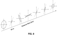
- the main axis is that on which the signal has a maximum amplitude, that is to say greater than all the other amplitudes of the signal on the same optical fiber slice. It is the main axis of the ellipse formed by the electric field of the electromagnetic wave at a given position of the fiber, the ellipse defining the state of polarization of the electromagnetic wave.
- the main optical axis varies throughout the optical fiber to always correspond to the axis on which the signal, at this point of the optical fiber, will present a maximum amplitude.
- projection axis within the meaning of the invention corresponds to the axis on which the electric field will oscillate, that is to say, where it is possible to observe the electric field oscillate.
- state of polarization within the meaning of the invention, the form defined by the movement of the orientation of the electric field in the plane of section perpendicular to the propagation of the electromagnetic wave.
- the state of polarization can then be rectilinear, ellipsoidal or circular.
- detection of a parameter or “ parameters of interest ” within the meaning of the invention means one or more characteristics of the backscattered vector electromagnetic wave such as amplitude, phase, state and degrees of polarization, vector dynamics , variations in index, optical path, birefringence, polarization mode dispersion.
- Coupled is meant in the sense of the invention, mixing, for example adding or multiplying two signals together.
- optical effects are known in fiber optic measurement including Brillouin, Raman and Rayleigh backscatter, and each of these techniques has different characteristics to determine different environmental influences, at different time scales.
- the optical fiber environmental parameters measurable using a fiber optic distributed measurement technique based on backscattering are related to the behaviors of the backscattered vector electromagnetic wave.
- the optical fiber environmental parameters currently measurable using a fiber optic distributed measurement technique based on Rayleigh backscattering are directly and linearly related to the phase of the backscattered electromagnetic wave.
- the quality of the measurement directly depends on the ability to correctly extract the phase of the backscattered electromagnetic wave.
- the inventors have therefore developed a method and a device making it possible to reconstruct a vector electromagnetic wave; the reconstruction of the backscattered vector electromagnetic wave making it possible to suppress the effect of fading induced by the polarization.
- the invention will be described in the context of Rayleigh type backscattering in an optical fiber, however, it is not limited to an optical fiber and can be implemented by any means capable of guiding a light wave.
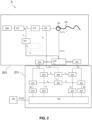
- FIG. 2 schematizes a device 3 for reconstructing a vector electromagnetic wave backscattered in all or part of an optical fiber 106.
- the backscattered vector electromagnetic wave can be reconstructed from a backscattered light signal in an optical fiber 106.
- the backscattered light signal may preferably correspond to a Rayleigh type backscatter signal.
- An optical fiber 106 according to the invention can correspond to any type of optical fiber configured to propagate and guide a light signal.
- an optical fiber according to the invention is a silica telecommunications optical fiber.
- a silica optical fiber reduces the losses during the propagation of the light wave in the optical fiber.
- an optical fiber 106 may correspond to a modified fiber to increase the backscatter process.
- “enhanced” fibers can be used. These fibers have the particularity of increased backscattering by increasing the impurities in the fiber or by the inclusion of Bragg gratings within them in order to increase the reflection of light.
- a reconstruction device 3 may comprise a light source 101 .
- the light source 101 is configured to generate a light signal.
- the light signal has for example a frequency v 0 .
- the light signal is capable of being injected into the optical fiber 106.
- a light source 101 can be a continuous optical source with a single optical pulse or a discontinuous optical source comprising several optical pulses (also called “pulse” in English terminology).
- the light source is continuous.
- a light source 101 according to the invention may be a narrowband source such as a distributed feedback fiber laser (which generally provides the narrowest possible spectrum of lasers available for which the emission wavelength can be selected over a wide range), a DFB laser (for "Distributed FeedBack" in English terminology) using a Bragg grating, or an external cavity laser (ECL for External Cavity Laser in English terminology).
- the emission wavelength ⁇ 0 is preferably equal or substantially equal to 1550 nm, at the corresponding frequency v 0 .
- the line of the emitted light wave is centered on the emission wavelength ⁇ 0 and has a large coherence length.
- the light source 101 for example a laser, emits a moderately powerful light signal, typically of the order of 20 mW, in an optical fiber 106.
- the light source 101 emits a light signal having a linear polarization state.
- a device making it possible to render the polarization state linear can be used.
- a reconstruction device 3 may comprise an optical coupler 102, preferably an optical coupler 102 with polarization maintenance.
- a polarization-maintaining coupler 102 is configured to divide the light signal from the light source 101 into two signals of identical frequency distributed in two arms. The first arm directs part of the light signal at frequency v 0 towards a local oscillator 107. The local oscillator is made up of a polarization-maintaining fiber. The second arm directs the other part of the light signal at the frequency v 0 towards the optical fiber 106 while preserving the initial polarization state from the light source 101.
- the use of a polarization-maintaining coupler 102 and of a polarization-maintaining fiber on the local oscillator makes it possible to maintain the outgoing polarization of the light source.
- the polarization stability of the local oscillator is improved. As this serves as a reference, in particular during polarization separation, its stability is crucial for the quality of the signal.
- a coupler 102 can correspond to a connector, mirror, lens, assembly of optical fibers (for example based on the fusion of a section of two optical fibers) making it possible to orient the light signal in a desired direction. It can be any means, preferably optical, configured to divide and direct the light signal while preserving its polarization state.
- a reconstruction device 3 according to the invention may comprise an optical amplifier 103.
- the amplifier is configured to amplify the signal. In particular, it is configured to increase and control signal strength.
- a reconstruction device 3 according to the invention may comprise an optical modulator 104.
- the modulator is preferably an acousto-optic modulator.
- the optical modulator can be arranged downstream of the optical amplifier.
- the modulator is configured to generate a train of pulses of predetermined duration and repetition rate. Multiple optical pulses can be transmitted in the optical fiber 106, the multiple optical pulses can be sent simultaneously or at different times.
- the multiple optical pulses can have different frequencies, polarizations and durations.
- the frequency v 0 is shifted with respect to the light signal coming from the light source 101 by a value equal to, or an integer multiple of, the predetermined frequency value of the modulator. Moreover, the frequency v 0 can also be offset with respect to the light signal coming from the light source 101 by a value equal to ⁇ v A .
- the frequency value of the modulator 104 corresponds to a frequency value equal to v A .
- a frequency v A is supplied following a control signal for the modulator 104.
- the pulse can be triggered by a trigger pulse control subunit.
- the optical pulse thus extracted from the modulator 104 is thus also shifted in frequency with respect to the input of the light signal into the modulator 104 from the light source 101, and also with respect to the signal of the local oscillator in the first arm.
- the modulator 104 is preferably able to impose a frequency shift of at least 10 Mhz on the continuous signal and to transform it into a pulsed signal intended to be injected into an optical fiber.
- the signal coming from the modulator comprises a DC component of frequency v 0 , transformed into an impulse component of frequency v 0 +v A .
- the modulator 104 is capable of generating a pulse signal having a frequency shifted with respect to the frequency of the continuous light signal.
- the frequency shift v A applied to said shifted frequency may be greater than or equal to 10 MHz.
- the frequency v A is the frequency specific to the modulator and is generally greater than or equal to 10 MHz and less than or equal to 1 GHz, preferably substantially equal to 200 MHz.
- the temporal width of the pulse thus generated can for example be between 10 ns and 500 ns, preferably it is substantially equal to 20 ns.
- the frequency shift may be implemented in the path of local oscillator 107.
- pulse generation and frequency shifting mechanisms can be used, such as electro-optic modulators or a combination of electro-optic modulators and electro-acoustic modulators.
- the frequency shift although not strictly necessary, is convenient in that it also allows the signals resulting from the combination of the reflected signals and the local oscillator to be distinguished from the light coming only from the path of the local oscillator or the backscattered signal.
- a trigger can be implemented to determine the moment at which the next pulse must be generated by the modulator 104.
- the optical modulator 104 thus makes it possible to reduce the effects of intra-pulse interference and therefore the noise. This feature is particularly advantageous when Rayleigh backscatter tracking is desired.
- the light signal preferably of frequency v 0 +v A is directed towards a circulator.
- an electric signal of frequency v A is also injected, preferably continuously, into the modulator, and directed to an amplifier 204.
- This signal serves as a reference for the frequency v A .
- a reconstruction device 3 may comprise an optical circulator 105 .
- the optical circulator 105 is arranged downstream of the modulator 104.
- the optical circulator 105 is configured to receive the light signal, for example coming from the coupler 102, from the modulator 104 or from the amplifier 103, preferably at an equal frequency at v 0 +v A .
- the optical circulator 105 is configured to inject the light signal into the optical fiber 106.
- the optical circulator 105 is configured to collect the backscatter, preferably Rayleigh, coming from the optical fiber 106.
- the signal at a frequency v 0 or v 0 +v A is injected into the optical fiber, which generates, in the opposite direction, a backscatter signal (eg Rayleigh) in response to the pulse.
- the Rayleigh backscatter signal has a frequency v 0 or v 0 +v A .
- the backscatter signal is separated from the forward going light to be directed to an optical splitter 202,303.
- a reconstruction device 3 comprises an optical coupling/separation means 202.
- the optical coupling/separation means 202 is preferably configured to couple the electromagnetic wave coming from the local oscillator 107 at a frequency v 0 +v A or v 0 with the Rayleigh backscatter signal from the optical fiber at a frequency v 0 or v 0 +v A .
- the optical coupling/separation means 202 is also configured to generate at least two backscattered light signals of orthogonal polarizations from a backscatter of the injected light signal. Said at least two backscattered light signals of orthogonal polarization exhibit for example a frequency at v 0 +v A , preferably a beat of at a frequency v A .
- a reconstruction device 3 comprises a polarization-resolved heterodyne optical detection 201.
- An optical coupling/separation means 202 can correspond to a splitter coupler, a polarization splitter coupler, a 90° hybridizer, a 180° hybridizer.
- the optical coupling/separation means may correspond to a 180° hybridizer.
- the polarization of the local oscillator is maintained and fixed at 45° with respect to the axes of the polarization separator making it possible to resolve the polarization quantitatively.
- the backscatter optical signal is first combined with the light signal from the local oscillator 107 to form a combined signal.
- a polarization beam splitter in the optical splitter means then splits the combined signal into at least two signal portions that have different polarizations (eg, orthogonal polarizations).
- this optical separation means makes it possible to attenuate polarization fading (that is to say the attenuation of the signal when the polarizations of the backscatter signal and of the signal of the local oscillator are not identical).
- the two polarizations may carry different information. This is particularly the case when asymmetric influences are applied to the fiber, such as a lateral force, which tends to act to vary the difference in propagation velocity between the two polarization modes of the fiber (i.e. say that it modifies the birefringence of the fiber).
- the optical separation means is then preferably configured to orient a first signal part corresponding to a first polarization towards a first photodetector 203, and a second signal part corresponding to a second different polarization is supplied to a second photodetector 203.
- a reconstruction device 3 comprises at least one photo-detector 203, preferably at least two photo-detectors 203. Said photo-detector(s) are configured to convert the backscattered light signals of orthogonal polarizations into analog signals initials.
- An initial analog signal from the photodetector preferably has a frequency v A .
- a photodetector 203 can correspond to a balanced photo-detector, photodiodes, avalanche photodiodes.
- the use of a 180° hybridizer with balanced photodetectors makes it possible to eliminate the losses associated with the splitter coupler.
- each initial analog signal from said at least two backscattered light signals of orthogonal polarization is an electrical signal oriented towards an electrical demodulator IQ.
- a reconstruction device 3 comprises an IQ demodulator 211,302.
- the IQ demodulator is arranged to perform homodyne electrical detection on each of the initial analog signals. It can for example be configured to carry out homodyne electrical detection at the frequency v A by mixing the initial analog signals detected for each of the polarizations with reference analog signals having a frequency v A .
- an IQ demodulator can be configured to produce a phase shift of part of the backscattered light signals, of part of the initial analog signals or of a reference analog signal at the frequency v A .
- an IQ demodulator is arranged so as to carry out an in-phase multiplication and a multiplication in phase quadrature of analog signals originating from each of the backscattered light signals of orthogonal polarization with a reference signal.
- part of the backscattered light signals, part of the initial analog signals or the reference analog signal at the frequency v A can pass through a phase shifter.
- the IQ demodulator may include at least one electrical mixer 205.
- the IQ demodulator includes two electrical mixers 205 for each initial analog signal.
- an initial analog signal originating from one of the at least two backscattered light signals of orthogonal polarization is oriented towards a sixth arm comprising an electric mixer 205 and towards a seventh arm also comprising an electric mixer 205.
- the initial analog signal from one of the at least two backscattered light signals of orthogonal polarization can be mixed, by an electric mixer 205, with a reference analog signal.
- the analog reference signal comes from the modulator 104 at a frequency v A .
- the reference signal can be generated from an external source.
- a reference analog signal may pass through several components configured to modify their properties.
- an analog reference signal can be previously directed to an intermediate amplifier 204.
- the intermediate amplifier 204 is preferably adjustable.
- the intermediate amplifier helps to amplify the signal result and increase the sensitivity.
- a reference analog signal coming from the intermediate amplifier 204 or directly from the modulator, can also be directed to a phase shifter 206 as illustrated in figure 2 .
- the IQ demodulator may include a phase shifter 206.
- the phase shifter is configured to phase shift the incident signal.
- a phase shifter 206 can correspond to a 90° phase shifter, ie shifting the incident signal by 90° in phase.
- the phase shifter 206 shifts the reference analog signal by 90° before it is directed to a mixer 205 arranged to mix it with an initial analog signal.
- the initial analog signal from one of the at least two backscattered light signals of orthogonal polarization can then be mixed with a phase-shifted reference analog signal from the phase shifter 206 by the electrical mixer 205 as illustrated in figure 2 .
- the IQ demodulator may include at least one phase shifter 206 configured to phase-shift an initial analog signal by 90° before it is directed to a mixer 205 arranged to mix it with a reference analog signal.
- an optical separation means 303 is preferably a 90° hybridizer.
- Such a hybridizer is furthermore configured to generate directly and optically the signal in phase I and in phase quadrature Q between the local oscillator and the signal of each orthogonal polarization.
- the use of a 90° hybridizer with balanced photodetectors makes it possible to eliminate the losses linked to the color separator.
- a first signal portion having a first bias is supplied to a first detector 203 and to a second detector in phase quadrature with respect to the latter.
- the second signal part having a second different polarization is supplied to a third detector 203 and to a fourth detector in phase quadrature with respect to the latter.
- an electrical phase shifter 206 is not necessary.
- the in-phase and quadrature-phase analog signals from the detectors 203 are each directly mixed with the signal from the modulator 104.
- the signal from the modulator 104 can also be amplified using an intermediate amplifier 204.
- the electrical mixers 205 operating at the heterodyne frequency mix the initial analog signals detected for each of the polarizations with reference analog signals, in phase or in phase quadrature (ie obtained using a phase shifter 206).
- the electrical mixers 205 operating at the heterodyne frequency mix the initial analog signals in phase or in phase quadrature for each of the polarizations (ie obtained using a phase shifter 206 or directly using a hybridizer as shown in figure 4 to an analog reference signal.
- the signal of interest preferably at the heterodyne frequency v A is thus brought back to baseband in phase I and in phase quadrature Q with respect to the local oscillator for each of the polarizations detected.
- the IQ demodulator may also include at least one filter 207.
- the IQ demodulator includes a filter 207 for each in-phase and quadrature-phase signal.
- a filter 207 can be used to select a band of frequencies above the zero frequency.
- a filter is configured to filter the signal of interest at the heterodyne frequency reduced to baseband.
- a filter according to the invention can correspond to a low-pass filter, a band-pass filter or a high-pass filter. Preferably, it is a low-pass filter.
- the filters preferably low-pass, make it possible to obtain the complex envelope of the signal corresponding to the backscattered vector electromagnetic wave for each of the two orthogonal polarizations.
- the signal of interest is not processed around a carrier frequency.
- obtaining the signal envelope allows accelerated digital reprocessing.
- the IQ demodulator may include an acquisition system 208.
- the acquisition system 208 is configured to convert the analog signal(s) into a digital signal.
- the acquisition system is configured to receive the in-phase and quadrature-phase signals carrying the amplitude and phase information for each of the two orthogonal polarizations.
- synchronization can be performed to trigger the acquisition cards at each light pulse generated by the modulator and injected into the optical fiber.
- the acquisition system can also be configured to sample the incoming signals in order to acquire the phase information therefrom.
- the IQ demodulator allows homodyne electrical detection allowing IQ type demodulation on each of the initial analog signals, to generate demodulated analog signals I (I 1 ,I 2 ) and Q (Q 1 ,Q 2 ) for each of the backscattered light signals orthogonal polarization, preferably initial analog signals corresponding to the two orthogonal polarizations.
- demodulated analog signals I (I 1 ,I 2 ) and Q (Q 1 ,Q 2 ) can be used to calculate a complex signal (l+jQ) which will include all the information necessary for the reconstruction of the real signal.
- the IQ demodulator being configured to carry out an in-phase and in-phase quadrature multiplication, the signal is divided into two orthogonal components linked by a trigonometric relationship. Part of the in-phase signal is cosine, while the other part of the quadrature-phase signal is sinusoid. Thus these two parts of the same signal become independent of each other such that the in-phase signal corresponds to the real part of the complex signal and the signal in phase quadrature corresponds to the imaginary part of the complex signal.
- the acquisition system makes it possible to determine the complex amplitude (l+jQ) for each of the two orthogonal polarizations. This makes it possible to calculate the phase and the amplitude of the backscattered signal more reliably and thus limit the attenuation or fading of the signal.
- low frequency noise is mostly filtered using a carrier frequency and electrical detection.
- the parallel acquisition on the two orthogonal polarizations of the complex amplitude (l+jQ) by IQ demodulation allows the reconstruction of the backscattered vector electromagnetic wave of a pulse propagating in all or part of the fiber optical.
- the demodulated analog signals I (I 1 ,I 2 ) and Q (Q 1 ,Q 2 ) can be used to calculate phase and amplitude values, which will allow access to all the information necessary for the reconstruction of the real signal.
- a reconstruction device 3 may comprise a processing module 209.
- the processing module is configured to reconstruct the vector electromagnetic wave backscattered in all or part of the optical fiber 106 according to the amplitude values (l+jQ) determined, or phase and amplitude values
- a mathematical relationship makes it possible to determine the backscattered vector electromagnetic wave as a function of complex amplitude values (l+jQ) determined from the demodulated analog signals I (I 1 ,I 2 ) and Q (Q 1 ,Q 2 ) generated.
- a mathematical relationship is also used to calculate complex amplitude values from phase and amplitude values.
- the processing module is advantageously configured to identify over all or part of the length of the optical fiber optical axes corresponding to the maximum amplitudes detected.
- the maximum amplitudes can be determined by mathematical calculation from the complex amplitude values (l+jQ) determined.
- the phase values can be calculated from the complex amplitude values (l+jQ) determined.
- the fading effect induced by the polarization is totally suppressed and above all the phase information is preserved, thus making it possible to exploit it.
- the processing module 209 is able to reconstruct the backscattered vector electromagnetic wave and therefore, for example, to calculate a main optical axis over a part or all along the optical fiber.
- the complex amplitudes containing the amplitude and phase information of the two orthogonal polarizations acquired by the system are combined and not processed separately to provide and exploit only one complex amplitude of interest depending on the position of the light pulse in the fiber.
- the reconstruction device 3 makes it possible to benefit from the advantages and particularly from the precision of a digital demodulation while avoiding sampling with sufficient resolution the frequency and having sufficient computing power for a digital phase extraction.
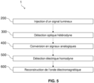
- the invention relates to a method 1 for reconstructing a vector electromagnetic wave backscattered in all or part of an optical fiber 106 as illustrated in figure 5 And 6 .
- a reconstruction method 1 comprises a step 200 of injecting into the optical fiber 106 a light signal, preferably of frequency v 0 +v A .
- the frequency v 0 +v A is preferably obtained by a frequency shift of a light signal of frequency v 0 .
- the frequency shift can be achieved by a modulator 104.
- the light signal of frequency v 0 can be generated by a light source 101.
- the method may include a step 200 of injecting into the optical fiber 106 a light signal of frequency v 0 .
- a light signal of frequency v 0 is the light signal which is oriented towards a local oscillator 107 which has a frequency v 0 +v A .
- the method can comprise a step of separating the light signal from the light source.
- the separation step can be performed by a polarization maintaining optical coupler 102.
- the light signal is divided into two parts of identical frequency v 0 .
- the signal is directed to two separate paths. Part of the light signal is directed to an amplifier 103 and the other part of the light signal is directed to a local oscillator 107.
- a method according to the invention may comprise a step 210 of amplifying the light signal. This step is implemented by an amplifier 103.
- the amplification step increases and controls the optical power of the light signal before the injection of the light signal into the optical fiber 106.
- a reconstruction method 1 according to the invention may comprise a step 220 of modulation of the light signal.
- the modulation can be performed by a modulator 104.
- the modulation is implemented before step 200 of injection into the optical fiber 106.
- the modulation can allow a shift in the frequency of the light signal by a value equal to vA .
- the frequency resulting from the modulation can be shifted (up or down) with respect to the frequency of the light signal resulting from the light source.
- Modulation can include generating different frequency pulses at a predetermined duration and repetition rate.
- the modulated light signal is injected into the optical fiber, which generates a Rayleigh backscatter signal.
- a reconstruction method 1 according to the invention may comprise a step 300 of polarization-resolved heterodyne optical detection.
- This optical detection step 300 advantageously comprises the generation of at least two backscattered light signals of orthogonal polarizations, producing a preferably beat of frequency v A .
- this generation can be carried out by an optical separation means and from backscattering of the injected light signal and an electromagnetic wave coming from a local oscillator.
- the backscattered light signal of frequency v 0 or v 0 +v A is then coupled with the light signal coming from the local oscillator 107 at a frequency v 0 or v 0 +v A .
- the coupling of the frequencies v 0 and v 0 +v A enables said at least two backscattered light signals of orthogonal polarization to preferably present a frequency v A .
- the signals when the backscatter signal is mixed with the signal from the local oscillator, the signals combine to provide a frequency difference that retains both the amplitude and phase information of the backscatter signal, provided that the local oscillator has a constant intensity and a sufficiently narrow band.
- the local oscillator and backscatter signals have a different frequency, so the step can correspond to heterodyne optical detection.
- Heterodyne detection consists in recombining the backscattered signal to be analyzed with the light signal from the local oscillator 107, the two having different frequencies.
- heterodyne detection is improved signal-to-noise ratio, as well as improved dynamic range since the heterodyne signal is proportional to the square root of the backscatter intensity.
- the generation step makes it possible to separate the mixture of the signals into two orthogonal polarizations. This alleviates polarization fading and signal attenuation when the polarizations of the backscatter signal and the local oscillator signal are not the same.
- the orthogonal polarization backscatter light signals are directed to at least two separate detectors 203, one for each of the orthogonal polarizations.
- the orthogonal polarization backscatter light signals can be directed to four separate detectors 203.
- a reconstruction method 1 according to the invention may comprise a step 400 of converting backscattered light signals of orthogonal polarizations into initial analog signals. Preferably, this step is performed by at least one photodetector 203.
- Each initial analog signal corresponding to one of the orthogonal polarization light signals is then directed to a step 500 of homodyne electrical detection.
- a reconstruction method 1 according to the invention may comprise a step 500 of homodyne electrical detection. This step is preferably carried out by an IQ demodulator allowing IQ type demodulation on each of the initial analog signals.
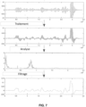
- a homodyne detection step according to one embodiment of the invention is illustrated in figure 7 . This homodyne electrical detection can be performed at the frequency v A by mixing the initial analog signals detected for each of the polarizations with reference analog signals having a frequency v A .
- Step 500 of homodyne electrical detection makes it possible to generate demodulated analog signals I (I 1 , I 2 ) and Q (Q 1 , Q 2 ) for each of the backscattered light signals of orthogonal polarization.
- Each analog signal corresponding to one of the light signals of orthogonal polarizations is divided into two parts before being directed to a step 525 of mixing.
- the mixing step 525 allows an in-phase multiplication and a multiplication in phase quadrature of analog signals originating from each of the backscattered light signals of orthogonal polarization with a reference signal.
- a method according to the invention may comprise a step 520 of phase shifting part of the backscattered light signals, part of the initial analog signals or part of the reference analog signal.
- the demodulation step IQ can comprise a phase shift step of a part of an analog reference signal at the frequency v A .
- this signal preferably electric, comes from the modulator 104.
- a single part of the reference analog signal at frequency v A is then phase-shifted then multiplied with each of the initial backscattered analog signals as shown in figure 2 .
- This embodiment has the advantage of using a photodiode balanced by detected polarizations and electrical IQ demodulation based on the phase shift of the frequency reference signal v A coming from the modulator whose properties remain constant over time. .
- the demodulation step IQ may comprise a step of phase shifting a part of the initial analog signals, preferably corresponding to a backscattered light signal, then a multiplication with an analog signal of reference.
- the demodulation step IQ may comprise a step of phase shifting a part of the initial analog signals, preferably corresponding to a backscattered light signal, then a multiplication with an analog signal of reference.
- This embodiment has the advantage of using a photodiode balanced by detected polarizations and electrical IQ demodulation.
- the IQ demodulation step may comprise a step of phase shifting part of the backscattered light signals as illustrated in figure 4 .
- the backscattered light signals are optically phase shifted which makes the electrical detection scheme simpler.
- This embodiment requires the use of four balanced photodetectors against only two for the two previous embodiments.
- the homodyne electrical detection step can include a phase shift step 520 .
- This step can be performed by at least one phase shifter 206.
- the heterodyne optical detection step includes a phase shift step. This step can be performed by a 90° hybridizer.
- phase shift step can be preceded or followed by an intermediate amplification step 510 .
- the intermediate amplification step corresponds to an amplification of the electric signal coming from the modulator 104 at the modulation frequency v A .
- the amplification step can be implemented by an intermediate amplifier.
- the signal coming from the modulator 104 and amplified can then be directed on the one hand towards the phase shift step 520 and on the other hand towards a mixing step.
- a method according to the invention may comprise a step of mixing 525 each of the initial analog signals corresponding to a backscattered light signal with the reference analog signal (in phase and/or or in phase quadrature), preferably coming from the modulator 104, at a frequency v A .
- this step is carried out by at least one electric mixer 205.
- each part of each initial analog signal from one of the two orthogonal polarization backscatter light signals is mixed on the one hand with a reference analog signal from the modulator 104, corresponding to an in-phase multiplication.
- the other part of each initial analog signal from one of the two orthogonal polarization backscatter light signals is mixed with a phase-shifted reference signal from the modulator 104 phase-shifted by 90°, corresponding to a phase quadrature multiplication of the signal.
- each initial analog signal coming from one of the two orthogonal polarization backscatter light signals can be phase shifted by 90° and be mixed with a reference signal coming from the modulator 104, corresponding to a multiplication in quadrature of phase.
- a method implemented by the invention may comprise an analog filtering step 530 making it possible to suppress part of the frequencies of the analog signals, preferably above a predetermined threshold.
- the analog filtering step corresponds to a high frequency filtering step. This allows to keep only the low frequencies.
- This step can be carried out by means of a low-pass filter 207.
- the filtering step makes it possible to overcome the noise that can be generated during the amplification and phase-shifting step, to keep only the signals in phase and in phase quadrature. This makes it possible to reduce the noise of the final signal.
- step 500 of homodyne electrical detection, by an IQ demodulator allowing IQ type demodulation for example on each of the analog signals of the backscattered light signals, makes it possible to generate demodulated analog signals I (I 1 , I 2 ) and Q (Q 1 ,Q 2 ) for each of the analog signals of the backscattered light signals.
- the two polarizations are detected in parallel in time-synchronized fashion, in other words at the same time.
- a method 1 of reconstruction according to the invention can comprise a step 600 of reconstruction of the vectorial electromagnetic wave backscattered in all or part of the optical fiber 106, preferably according to complex amplitude values (l+jQ) or phase and amplitude values determined from the demodulated analog signals I (I 1 ,I 2 ) and Q (Q 1 ,Q 2 ) generated.
- This step can be carried out by a processing module 209, as illustrated in figure 8 and at the figure 9 .
- these demodulated analog signals I (I 1 ,I 2 ) and Q (Q 1 ,Q 2 ) can be used to calculate a complex signal (l+jQ) which will include all the information necessary for the reconstruction of the real signal and therefore to the reconstruction of the vectorial electromagnetic wave.
- These demodulated analog signals I (I 1 ,I 2 ) and Q (Q 1 ,Q 2 ) can be used to calculate phase and amplitude values which will include all the information necessary for the reconstruction of the real signal and therefore for the vector electromagnetic wave reconstruction.
- the method can comprise a step 610a of complex amplitude calculation (l+jQ) from the demodulated analog signals I (I 1 ,I 2 ) and Q (Q 1 ,Q 2 ).
- the step of reconstructing the backscattered vector electromagnetic wave can comprise a step of calculating the phase and/or the amplitude of the backscattered light signal from the complex amplitudes (l+jQ) determined.
- this calculation step is performed in all or part of the optical fiber.
- this step can be performed for any projection axes in all or part of the optical fiber depending on the complex amplitude values (l+jQ) determined from the demodulated analog signals I (I 1 , I 2 ) and Q (Q 1 ,Q 2 ) generated.
- a method according to the invention can comprise a step 610b of phase and amplitude calculation from the demodulated analog signals I (I 1 ,I 2 ) and Q (Q 1 ,Q 2 ).
- the step of reconstructing the backscattered vector electromagnetic wave may comprise a step of calculating the complex amplitude (l+jQ), in all or part of the optical fiber from the phase and amplitude values calculated from the demodulated analog signals I (I 1 , I 2 ) and Q (Q 1 , Q 2 ) generated.
- the method may include a step of calculating the complex amplitude of the backscattered light signal from the determined phase and amplitude values. Preferably, this calculation step is performed in all or part of the optical fiber.
- a plurality of amplitude values and/or phase values are obtained in all or part of the optical fiber and for each light signal of orthogonal polarization.
- the reconstruction step 600 can include a complex amplitude calculation and/or the amplitude and/or the phase of the backscattered signal for all the angles of the electric field and over all or part of the optical fibre.
- the calculation of complex amplitude and or of the amplitude and/or of the phase for all the angles of the electric field can correspond to the creation of a vector, by change of frame of reference.
- the angle is for example between 0 and 2 ⁇ .
- the calculation of a maximum amplitude comprises the identification of an optimal angle associated with the maximum amplitude for all axes of projection in all or part of the optical fiber.
- the optimal angle preferably corresponding to the angle having the highest maximum amplitude among amplitudes of a plurality of angles corresponding to the projection axes in all or part of the optical fiber, preferably to the projection axes defined in the section plane in all or part of the optical fiber.
- the calculation is performed at a plurality of points on all or part of the optical fiber.
- the behavior of the backscattered vector electromagnetic wave in all or part of the optical fiber can be characterized and therefore the backscattered vector electromagnetic wave reconstructed.
- Totally reconstructing the backscattered vector electromagnetic wave also allows complete and simultaneous access to the properties which characterize it (amplitude, phase, state of polarization, degree of polarization) and which electromagnetically characterize its propagation medium (variation of index, optical path, birefringence, modal dispersion of polarization) and those distributed in all or part of the fiber.
- these properties can be used in isolation or in combination to determine in a distributed manner in all or part of the optical fiber interrogated a variation of one or more environmental influences acting on the behavior of the electromagnetic wave.
- the maximum amplitude calculation includes the identification of an angle from a plurality of angles corresponding to the possible projection axes defined in the section plane of the fiber in all or part of the corresponding optical fiber to the main optical axis.
- the maximum amplitudes can be determined by mathematical calculation from the complex amplitude values (l+jQ) or from the phase and corresponding amplitude values determined.
- the corresponding phase values can be calculated from the complex amplitude values (l+jQ) determined.
- a method according to the invention may comprise a step 700 of detecting a parameter of interest, as illustrated in particular in figure 8 .
- a method according to the invention can also comprise a step 710 of extracting a phase profile. This step is preferably carried out for each projection carried out and/or for each phase calculated from the complex amplitudes (l+jQ) determined. Indeed, for each projection, the phase can be deduced which makes it possible to deduce a phase profile.
- a method according to the invention may comprise a step 720 of phase unwinding.
- the phase being circular, it varies according to an angle between 0 and 2 ⁇ ( ⁇ and - ⁇ ).
- this phase is added to ⁇ .
- the phase extraction or calculation is no longer limited to a single optical axis and therefore to the phenomenon of fading.
- a method according to the invention may comprise a step of identifying 730, over all or part of the length of the optical fiber 106, the main optical axis corresponding to the maximum amplitudes or to the angle having the greatest amplitude compared to the whole calculated amplitudes.
- identification is presented on the figure 10 .
- each optical axis comprises a different amplitude and a different phase, the behavior of the electric field of the backscattered electromagnetic wave then being different in all or part of the optical fiber.
- this step consists in determining on all or part of the optical fiber the optical axes on which the amplitude of the signal is the greatest.
- Such a step can in particular comprise a projection of the complex amplitudes on each optical axis.
- the processing module is capable of reconstructing a main optical axis as a function of the calculated amplitude and phase values.
- a reconstruction method 1 according to the invention also makes it possible, for example, to identify a specific angle, to compare different angles of one or more optical fibers or even to identify specific axes and their different evolutions.
- the invention is particularly advantageous in the sense that it makes it possible to mitigate the phenomenon of fading and of surplus to recover more than 3 dB which can be lost following the couplers. Thus, it is possible to recover more than 50% of the signal and greatly improve the analyzes by distributed measurements by optical fiber and by Rayleigh backscatter.
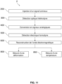
- the invention relates to a method 2 of optoelectronic measurement in a distributed acoustic detection system as illustrated in figure 11 .
- the distributed acoustic sensing system detects vibrations and captures the acoustic energy along the optical fiber.
- DAS Distributed Acoustic Sensing in Anglo-Saxon terminology
- This system makes it possible to detect acoustic frequency signals over large distances.
- the acoustic disturbance on the fiber generates its elongation or its compression which causes a change of phase relationship.
- this method may include a comparison to determine how the phase varies from one point of the optical fiber to another as the phase difference is proportional to the elongation or compression of the fiber.
- the measurement of the phase difference is preferably carried out on the main optical axis which corresponds to the axis where the phase extraction is optimized.
- this step makes it possible to determine how the phase varies between two points.
- these systems are inexpensive and highly reliable.
- a method 2 of optoelectronic measurement can comprise a reconstruction of a vectorial electromagnetic wave backscattered in all or part of an optical fiber 106 according to the invention and as described above.
- a method 2 of optoelectronic measurement can comprise a measurement of a deformation 800 and/ or of a temperature variation 850 of the optical fiber 106 as a function of the reconstructed backscattered vector electromagnetic wave.
- a light signal When a light signal is backscattered, it contains information related to the environmental influences of the fibre. Thus, if the environment of the optical fiber undergoes a constraint (deformation for example), the signal backscattered from the fiber will include the information of this deformation.
- the optical fiber allows a measurement of a deformation 800 but also of a temperature variation 850.
- the difference in phase or amplitude of the backscatter signal as being an incident stress on the optical fiber
- other parameters such as temperature changes
- the stress on the fiber can result from other external effects than those discussed above.
- a change in pressure in the fiber can cause stress on the fiber, such as conversion of pressure to stress by the fiber coating.
- a method 2 of optoelectronic measurement can comprise a measurement of a deformation of the optical fiber 106 on the reconstructed optical main axis.
- the electromagnetic wave is linked to the main optical axis.
- the main optical axis can also be reconstructed.
- the method according to the invention also comprises a measurement of a deformation of the optical fiber or a temperature variation on the main optical axis reconstructed according to the invention.
- the measurement of the deformation is carried out by an optical fiber.
- DAS signals are known for optical fading, in which the signal intensity is time-dependent, due to slow changes in the fiber that cause optical path length changes.
- the system can be optimized in order to generate better signal analysis by DAS.
- Totally reconstructing the backscattered vector electromagnetic wave also allows complete and simultaneous access to the properties which characterize it (amplitude, phase, state of polarization, degree of polarization) and which electromagnetically characterize its propagation medium (variation of index, optical path, birefringence, modal dispersion of polarization) and those distributed in all or part of the fiber.
- these properties can be used in isolation or in combination to determine in a distributed manner in all or part of the optical fiber interrogated a variation of one or more environmental influences acting on the behavior of the electromagnetic wave.
- FIG. 12A An exemplary embodiment of a method according to the invention and techniques of the prior art are illustrated in Figures 12A, 12B, 12C .
- a first detection with a 180° hybridizer (H180) with electronic IQ detection is carried out and reported on the Figure 12A .
- This example illustrates the amplitude and phase results obtained by a method according to the invention, as illustrated in picture 2 .
- the amplitude profile is obtained and this in a particularly precise manner.
- such a method has very little noise. Thanks to such quality of amplitude results, it is easy to calculate or deduce the phase in order to characterize and therefore to reconstruct the backscattered vector electromagnetic wave.
- the electric vector as previously described, oscillates according to the environmental influences that occur on the fiber. Such an electric vector oscillates according to a phase and an amplitude. Thanks to the method according to the invention, the amplitude and the phase obtained are not very noisy, it is therefore particularly more advantageous to extract the amplitude and phase values characterizing the backscattered vector electromagnetic wave for each polarization.
- the reconstruction of the backscattered vector electromagnetic wave makes it possible to characterize several environmental influences that may be exerted on all or part of the optical fiber.
- the method does not present any discontinuity in time and in space.
- a second detection is carried out with a 90° hybridizer (H90) with an optoelectronic IQ detection and reported on the figure 12B .
- H90 90° hybridizer
- This example illustrates the results obtained by a method according to the invention as illustrated in figure 4 .
- the amplitude and phase profile show more noise than with H180 detection with electronic IQ detection, however, it is easy to find the exact amplitude and phase using this detection.
- phase extraction is performed with very little noise, even for weak signals in the optical fiber.
- the phase extraction is done on the projection of the electric field.
- the attenuation of the fading phenomenon relies entirely on the physical properties of the electromagnetic wave guided in the optical fiber.
- the reconstruction makes it possible to opt for the most favorable case for the least noisy extraction of the phase.
- the invention has the advantage of being less complex than systems using optical frequency diversity to attenuate the fading effect.
- a third detection is carried out with a 90° hybridizer (H90) with optical homodyne IQ detection and reported on the figure 12C .
- This homodyne detection is therefore purely and solely optical unlike the invention and represents one of the techniques of the prior art as proposed in the reference.
- Such detection generates significant noise both at the level of the amplitude profile and of the phase extraction. Thus, it is not possible to go back to the information supported by the electromagnetic wave, or to reconstruct the backscattered vector electromagnetic wave.
- the amplitude and phase are very noisy. Indeed, the low frequency noise is not filtered by the frequency of the carrier and the electrical detection. Thus, the signal is totally noisy to such an extent that no information can be extracted from it.
- a method according to the invention is therefore particularly advantageous and makes it possible to meet existing needs in the field of distributed measurements by optical fiber.
- FIG. 13 Another comparative example of an end result is shown in figure 13 .
- the different measurements are obtained from a DAS.
- the measurements represented by the gray curve illustrate the results of the prior art and the black curve represents the measurements obtained according to a method according to the invention.
- the gray curve represents the extraction of different phases along the optical fiber to find a deformation. However, this is performed on a single and unique polarization, on a single fixed axis. Additionally, significant noise is present.
- the black curve illustrating the method according to the invention and comprising the identification of a main optical axis in all or part of the optical fiber, makes it possible to obtain results whose measurement quality is improved and whose noise is minimized.
Landscapes
- Physics & Mathematics (AREA)
- General Physics & Mathematics (AREA)
- Electromagnetism (AREA)
- Engineering & Computer Science (AREA)
- Computer Networks & Wireless Communication (AREA)
- Signal Processing (AREA)
- Optical Transform (AREA)
- Optical Communication System (AREA)
- Investigating Or Analysing Materials By Optical Means (AREA)
- Radar Systems Or Details Thereof (AREA)
Applications Claiming Priority (2)
| Application Number | Priority Date | Filing Date | Title |
|---|---|---|---|
| FR1908568A FR3099245B1 (fr) | 2019-07-26 | 2019-07-26 | Procede et dispositif de reconstruction d’une onde electromagnetique vectorielle retrodiffusee |
| PCT/FR2020/051368 WO2021019171A1 (fr) | 2019-07-26 | 2020-07-26 | Procede et dispositif de reconstruction d'une onde electromagnetique vectorielle retrodiffusee |
Publications (2)
| Publication Number | Publication Date |
|---|---|
| EP3997419A1 EP3997419A1 (fr) | 2022-05-18 |
| EP3997419B1 true EP3997419B1 (fr) | 2023-05-24 |
Family
ID=69024308
Family Applications (1)
| Application Number | Title | Priority Date | Filing Date |
|---|---|---|---|
| EP20757642.2A Active EP3997419B1 (fr) | 2019-07-26 | 2020-07-26 | Procede et dispositif de reconstruction d'une onde electromagnetique vectorielle retrodiffusee |
Country Status (7)
| Country | Link |
|---|---|
| US (1) | US11725965B2 (zh) |
| EP (1) | EP3997419B1 (zh) |
| CN (1) | CN114424029B (zh) |
| CA (1) | CA3148746A1 (zh) |
| ES (1) | ES2954238T3 (zh) |
| FR (1) | FR3099245B1 (zh) |
| WO (1) | WO2021019171A1 (zh) |
Families Citing this family (4)
| Publication number | Priority date | Publication date | Assignee | Title |
|---|---|---|---|---|
| IT202200004667A1 (it) | 2022-03-11 | 2022-06-11 | Sestosensor S R L | Rivelatore di fase e polarizzazione per sensori acustici distribuiti a fibre ottiche ed interrogatore basato sullo stesso |
| WO2023236144A1 (zh) * | 2022-06-09 | 2023-12-14 | Oppo广东移动通信有限公司 | 无线通信的方法和设备 |
| CN115406490A (zh) * | 2022-11-02 | 2022-11-29 | 高勘(广州)技术有限公司 | 光缆管道监测方法、装置、设备及存储介质 |
| CN116399379B (zh) * | 2023-06-07 | 2023-11-03 | 山东省科学院激光研究所 | 分布式光纤声波传感系统及其测量方法 |
Family Cites Families (10)
| Publication number | Priority date | Publication date | Assignee | Title |
|---|---|---|---|---|
| IT1189657B (it) * | 1986-04-10 | 1988-02-04 | Cselt Centro Studi Lab Telecom | Sistema di trasmissione in fibra ottica a modulazione di polarizzazione e rivelazione coerente eterodina |
| KR100866038B1 (ko) * | 2007-08-01 | 2008-11-05 | 서강대학교산학협력단 | 헤테로다인 간섭계를 이용한 주사 현미경 |
| US8401401B2 (en) * | 2008-10-14 | 2013-03-19 | Schlumberger Technology Corporation | Polarization-diverse, heterodyne optical receiving system |
| CA2809660C (en) * | 2010-09-01 | 2016-11-15 | Schlumberger Canada Limited | Distributed fiber optic sensor system with improved linearity |
| US20130113629A1 (en) | 2011-11-04 | 2013-05-09 | Schlumberger Technology Corporation | Phase sensitive coherent otdr with multi-frequency interrogation |
| US9009003B1 (en) | 2012-05-03 | 2015-04-14 | The United States Of America As Represented By The Administrator Of The National Aeronautics And Space Administration | Apparatus and method for elimination of polarization-induced fading in fiber-optic sensor system |
| US10247581B2 (en) * | 2014-04-28 | 2019-04-02 | Optoplan As | Interferometric optical fibre sensor system and method of interrogation |
| CN104567960B (zh) * | 2015-01-04 | 2017-04-05 | 西南交通大学 | 一种基于相位调制探测光的相干布里渊光时域分析传感系统 |
| US9628314B1 (en) * | 2015-04-15 | 2017-04-18 | The United States Of America As Represented By The Secretary Of The Navy | Digital I/Q reprocessing demodulator (DIRD) |
| CN110048765B (zh) * | 2018-09-30 | 2021-06-22 | 南京大学 | 一种基于整体最小二乘拟合的φ-otdr定量测量的方法 |
-
2019
- 2019-07-26 FR FR1908568A patent/FR3099245B1/fr active Active
-
2020
- 2020-07-26 ES ES20757642T patent/ES2954238T3/es active Active
- 2020-07-26 EP EP20757642.2A patent/EP3997419B1/fr active Active
- 2020-07-26 US US17/628,944 patent/US11725965B2/en active Active
- 2020-07-26 CA CA3148746A patent/CA3148746A1/en active Pending
- 2020-07-26 WO PCT/FR2020/051368 patent/WO2021019171A1/fr unknown
- 2020-07-26 CN CN202080066030.6A patent/CN114424029B/zh active Active
Also Published As
| Publication number | Publication date |
|---|---|
| US11725965B2 (en) | 2023-08-15 |
| EP3997419A1 (fr) | 2022-05-18 |
| WO2021019171A1 (fr) | 2021-02-04 |
| FR3099245B1 (fr) | 2021-07-30 |
| FR3099245A1 (fr) | 2021-01-29 |
| CN114424029B (zh) | 2023-07-18 |
| CA3148746A1 (en) | 2021-02-04 |
| ES2954238T3 (es) | 2023-11-21 |
| CN114424029A (zh) | 2022-04-29 |
| US20220252435A1 (en) | 2022-08-11 |
Similar Documents
| Publication | Publication Date | Title |
|---|---|---|
| EP3997419B1 (fr) | Procede et dispositif de reconstruction d'une onde electromagnetique vectorielle retrodiffusee | |
| US8144334B2 (en) | Fiber-optic, digital system for laser Doppler vibrometers (LDVs) | |
| EP3353502B1 (fr) | Systeme de mesure et capteur de temperature et/ou de deformation par analyse de retroreflexion brillouin. | |
| FR3034190B1 (fr) | Capteur a fibre optique distribue d'etat de contrainte | |
| AU2020102296A4 (en) | A distributed optical fiber sensing system based on heterodyne detection technology | |
| FR3098659A1 (fr) | Dispositif laser de balayage d'impulsion de modulation ultra-rapide EHz et un système de détection à fibres optiques distribuées | |
| WO1998019142A1 (fr) | Composant optique de modulation de polarisation, et son utilisation dans un polarimetre ou dans un ellipsometre | |
| WO2018207163A2 (fr) | Dispositif optoélectronique de mesure répartie par fibre optique | |
| FR3059099A1 (fr) | Systeme de detection d'onde acoustique a fibre acoustique | |
| EP2405287B1 (fr) | Dispositif dé telédétection laser et procédé d'interférometrie | |
| WO2012175451A1 (fr) | Systeme et procede d'analyse par determination d'un caractere depolarisant ou dichroïque d'un objet | |
| EP3899497B1 (fr) | Dispositif laser pour interferometrie a polarisation | |
| EP0291368B1 (fr) | Procédé et dispositif de détection des variations de temps de propagation dans un interféromètre en anneau, et leur application au contrôle de longueur d'onde | |
| EP3044697B1 (fr) | Procédé électronique d'extraction de l'amplitude et de la phase d'un signal dans une détection synchrone et montage interférométrique pour la mise en oeuvre du procédé | |
| EP2793425B1 (fr) | Procédé et système pour déterminer un bruit de photon dans des dispositifs de communication optique | |
| EP2936057B1 (fr) | Dispositif de mesure interférométrique comportant un interféromètre de filtrage | |
| WO2022122594A1 (fr) | Dispositif d'analyse spectrale large bande d'un signal d'intérêt | |
| EP1459464B1 (fr) | Systeme de transmission optique en propagation libre | |
| EP4078217B1 (fr) | Systeme lidar comprenant deux composants diffractifs | |
| EP4310457A1 (fr) | Système de capteur à fibre optique distribué | |
| EP4256419A1 (fr) | Dispositif large bande de mesure de la corrélation croisée de signaux | |
| EP0635730A1 (fr) | Vélocimètre à hologramme dynamique | |
| Sylvestre et al. | Capteur Brillouin réparti à fibre optique à haute résolution et longue portée |
Legal Events
| Date | Code | Title | Description |
|---|---|---|---|
| STAA | Information on the status of an ep patent application or granted ep patent |
Free format text: STATUS: UNKNOWN |
|
| STAA | Information on the status of an ep patent application or granted ep patent |
Free format text: STATUS: THE INTERNATIONAL PUBLICATION HAS BEEN MADE |
|
| PUAI | Public reference made under article 153(3) epc to a published international application that has entered the european phase |
Free format text: ORIGINAL CODE: 0009012 |
|
| STAA | Information on the status of an ep patent application or granted ep patent |
Free format text: STATUS: REQUEST FOR EXAMINATION WAS MADE |
|
| 17P | Request for examination filed |
Effective date: 20220211 |
|
| AK | Designated contracting states |
Kind code of ref document: A1 Designated state(s): AL AT BE BG CH CY CZ DE DK EE ES FI FR GB GR HR HU IE IS IT LI LT LU LV MC MK MT NL NO PL PT RO RS SE SI SK SM TR |
|
| DAV | Request for validation of the european patent (deleted) | ||
| DAX | Request for extension of the european patent (deleted) | ||
| GRAP | Despatch of communication of intention to grant a patent |
Free format text: ORIGINAL CODE: EPIDOSNIGR1 |
|
| STAA | Information on the status of an ep patent application or granted ep patent |
Free format text: STATUS: GRANT OF PATENT IS INTENDED |
|
| RIC1 | Information provided on ipc code assigned before grant |
Ipc: H04B 10/25 20130101ALI20221205BHEP Ipc: G01D 5/353 20060101AFI20221205BHEP |
|
| INTG | Intention to grant announced |
Effective date: 20221221 |
|
| GRAS | Grant fee paid |
Free format text: ORIGINAL CODE: EPIDOSNIGR3 |
|
| GRAA | (expected) grant |
Free format text: ORIGINAL CODE: 0009210 |
|
| STAA | Information on the status of an ep patent application or granted ep patent |
Free format text: STATUS: THE PATENT HAS BEEN GRANTED |
|
| AK | Designated contracting states |
Kind code of ref document: B1 Designated state(s): AL AT BE BG CH CY CZ DE DK EE ES FI FR GB GR HR HU IE IS IT LI LT LU LV MC MK MT NL NO PL PT RO RS SE SI SK SM TR |
|
| REG | Reference to a national code |
Ref country code: GB Ref legal event code: FG4D Free format text: NOT ENGLISH |
|
| REG | Reference to a national code |
Ref country code: CH Ref legal event code: EP |
|
| REG | Reference to a national code |
Ref country code: DE Ref legal event code: R096 Ref document number: 602020011161 Country of ref document: DE |
|
| REG | Reference to a national code |
Ref country code: AT Ref legal event code: REF Ref document number: 1569764 Country of ref document: AT Kind code of ref document: T Effective date: 20230615 |
|
| REG | Reference to a national code |
Ref country code: IE Ref legal event code: FG4D Free format text: LANGUAGE OF EP DOCUMENT: FRENCH |
|
| REG | Reference to a national code |
Ref country code: LT Ref legal event code: MG9D |
|
| REG | Reference to a national code |
Ref country code: NL Ref legal event code: MP Effective date: 20230524 |
|
| P01 | Opt-out of the competence of the unified patent court (upc) registered |
Effective date: 20230828 |
|
| REG | Reference to a national code |
Ref country code: AT Ref legal event code: MK05 Ref document number: 1569764 Country of ref document: AT Kind code of ref document: T Effective date: 20230524 |
|
| PG25 | Lapsed in a contracting state [announced via postgrant information from national office to epo] |
Ref country code: SE Free format text: LAPSE BECAUSE OF FAILURE TO SUBMIT A TRANSLATION OF THE DESCRIPTION OR TO PAY THE FEE WITHIN THE PRESCRIBED TIME-LIMIT Effective date: 20230524 Ref country code: PT Free format text: LAPSE BECAUSE OF FAILURE TO SUBMIT A TRANSLATION OF THE DESCRIPTION OR TO PAY THE FEE WITHIN THE PRESCRIBED TIME-LIMIT Effective date: 20230925 Ref country code: NO Free format text: LAPSE BECAUSE OF FAILURE TO SUBMIT A TRANSLATION OF THE DESCRIPTION OR TO PAY THE FEE WITHIN THE PRESCRIBED TIME-LIMIT Effective date: 20230824 Ref country code: NL Free format text: LAPSE BECAUSE OF FAILURE TO SUBMIT A TRANSLATION OF THE DESCRIPTION OR TO PAY THE FEE WITHIN THE PRESCRIBED TIME-LIMIT Effective date: 20230524 Ref country code: AT Free format text: LAPSE BECAUSE OF FAILURE TO SUBMIT A TRANSLATION OF THE DESCRIPTION OR TO PAY THE FEE WITHIN THE PRESCRIBED TIME-LIMIT Effective date: 20230524 |
|
| PGFP | Annual fee paid to national office [announced via postgrant information from national office to epo] |
Ref country code: IT Payment date: 20230731 Year of fee payment: 4 |
|
| REG | Reference to a national code |
Ref country code: ES Ref legal event code: FG2A Ref document number: 2954238 Country of ref document: ES Kind code of ref document: T3 Effective date: 20231121 |
|
| PG25 | Lapsed in a contracting state [announced via postgrant information from national office to epo] |
Ref country code: RS Free format text: LAPSE BECAUSE OF FAILURE TO SUBMIT A TRANSLATION OF THE DESCRIPTION OR TO PAY THE FEE WITHIN THE PRESCRIBED TIME-LIMIT Effective date: 20230524 Ref country code: PL Free format text: LAPSE BECAUSE OF FAILURE TO SUBMIT A TRANSLATION OF THE DESCRIPTION OR TO PAY THE FEE WITHIN THE PRESCRIBED TIME-LIMIT Effective date: 20230524 Ref country code: LV Free format text: LAPSE BECAUSE OF FAILURE TO SUBMIT A TRANSLATION OF THE DESCRIPTION OR TO PAY THE FEE WITHIN THE PRESCRIBED TIME-LIMIT Effective date: 20230524 Ref country code: LT Free format text: LAPSE BECAUSE OF FAILURE TO SUBMIT A TRANSLATION OF THE DESCRIPTION OR TO PAY THE FEE WITHIN THE PRESCRIBED TIME-LIMIT Effective date: 20230524 Ref country code: IS Free format text: LAPSE BECAUSE OF FAILURE TO SUBMIT A TRANSLATION OF THE DESCRIPTION OR TO PAY THE FEE WITHIN THE PRESCRIBED TIME-LIMIT Effective date: 20230924 Ref country code: HR Free format text: LAPSE BECAUSE OF FAILURE TO SUBMIT A TRANSLATION OF THE DESCRIPTION OR TO PAY THE FEE WITHIN THE PRESCRIBED TIME-LIMIT Effective date: 20230524 Ref country code: GR Free format text: LAPSE BECAUSE OF FAILURE TO SUBMIT A TRANSLATION OF THE DESCRIPTION OR TO PAY THE FEE WITHIN THE PRESCRIBED TIME-LIMIT Effective date: 20230825 |
|
| PGFP | Annual fee paid to national office [announced via postgrant information from national office to epo] |
Ref country code: FR Payment date: 20230731 Year of fee payment: 4 |
|
| PG25 | Lapsed in a contracting state [announced via postgrant information from national office to epo] |
Ref country code: FI Free format text: LAPSE BECAUSE OF FAILURE TO SUBMIT A TRANSLATION OF THE DESCRIPTION OR TO PAY THE FEE WITHIN THE PRESCRIBED TIME-LIMIT Effective date: 20230524 |
|
| PGFP | Annual fee paid to national office [announced via postgrant information from national office to epo] |
Ref country code: LU Payment date: 20231019 Year of fee payment: 4 |
|
| PG25 | Lapsed in a contracting state [announced via postgrant information from national office to epo] |
Ref country code: SK Free format text: LAPSE BECAUSE OF FAILURE TO SUBMIT A TRANSLATION OF THE DESCRIPTION OR TO PAY THE FEE WITHIN THE PRESCRIBED TIME-LIMIT Effective date: 20230524 |
|
| PGFP | Annual fee paid to national office [announced via postgrant information from national office to epo] |
Ref country code: ES Payment date: 20231020 Year of fee payment: 4 |
|
| PG25 | Lapsed in a contracting state [announced via postgrant information from national office to epo] |
Ref country code: SM Free format text: LAPSE BECAUSE OF FAILURE TO SUBMIT A TRANSLATION OF THE DESCRIPTION OR TO PAY THE FEE WITHIN THE PRESCRIBED TIME-LIMIT Effective date: 20230524 Ref country code: SK Free format text: LAPSE BECAUSE OF FAILURE TO SUBMIT A TRANSLATION OF THE DESCRIPTION OR TO PAY THE FEE WITHIN THE PRESCRIBED TIME-LIMIT Effective date: 20230524 Ref country code: RO Free format text: LAPSE BECAUSE OF FAILURE TO SUBMIT A TRANSLATION OF THE DESCRIPTION OR TO PAY THE FEE WITHIN THE PRESCRIBED TIME-LIMIT Effective date: 20230524 Ref country code: EE Free format text: LAPSE BECAUSE OF FAILURE TO SUBMIT A TRANSLATION OF THE DESCRIPTION OR TO PAY THE FEE WITHIN THE PRESCRIBED TIME-LIMIT Effective date: 20230524 Ref country code: DK Free format text: LAPSE BECAUSE OF FAILURE TO SUBMIT A TRANSLATION OF THE DESCRIPTION OR TO PAY THE FEE WITHIN THE PRESCRIBED TIME-LIMIT Effective date: 20230524 Ref country code: CZ Free format text: LAPSE BECAUSE OF FAILURE TO SUBMIT A TRANSLATION OF THE DESCRIPTION OR TO PAY THE FEE WITHIN THE PRESCRIBED TIME-LIMIT Effective date: 20230524 |
|
| PGFP | Annual fee paid to national office [announced via postgrant information from national office to epo] |
Ref country code: IE Payment date: 20231003 Year of fee payment: 4 Ref country code: DE Payment date: 20231006 Year of fee payment: 4 Ref country code: CH Payment date: 20231022 Year of fee payment: 4 |
|
| REG | Reference to a national code |
Ref country code: DE Ref legal event code: R097 Ref document number: 602020011161 Country of ref document: DE |
|
| PG25 | Lapsed in a contracting state [announced via postgrant information from national office to epo] |
Ref country code: MC Free format text: LAPSE BECAUSE OF FAILURE TO SUBMIT A TRANSLATION OF THE DESCRIPTION OR TO PAY THE FEE WITHIN THE PRESCRIBED TIME-LIMIT Effective date: 20230524 |
|
| PG25 | Lapsed in a contracting state [announced via postgrant information from national office to epo] |
Ref country code: MC Free format text: LAPSE BECAUSE OF FAILURE TO SUBMIT A TRANSLATION OF THE DESCRIPTION OR TO PAY THE FEE WITHIN THE PRESCRIBED TIME-LIMIT Effective date: 20230524 |
|
| PGFP | Annual fee paid to national office [announced via postgrant information from national office to epo] |
Ref country code: BE Payment date: 20231019 Year of fee payment: 4 |
|
| PLBE | No opposition filed within time limit |
Free format text: ORIGINAL CODE: 0009261 |
|
| STAA | Information on the status of an ep patent application or granted ep patent |
Free format text: STATUS: NO OPPOSITION FILED WITHIN TIME LIMIT |
|
| 26N | No opposition filed |
Effective date: 20240227 |
|
| PG25 | Lapsed in a contracting state [announced via postgrant information from national office to epo] |
Ref country code: SI Free format text: LAPSE BECAUSE OF FAILURE TO SUBMIT A TRANSLATION OF THE DESCRIPTION OR TO PAY THE FEE WITHIN THE PRESCRIBED TIME-LIMIT Effective date: 20230524 |