EP3997419B1 - Method and device for reconstructing a backscattered electromagnetic vector wave - Google Patents
Method and device for reconstructing a backscattered electromagnetic vector wave Download PDFInfo
- Publication number
- EP3997419B1 EP3997419B1 EP20757642.2A EP20757642A EP3997419B1 EP 3997419 B1 EP3997419 B1 EP 3997419B1 EP 20757642 A EP20757642 A EP 20757642A EP 3997419 B1 EP3997419 B1 EP 3997419B1
- Authority
- EP
- European Patent Office
- Prior art keywords
- optical fiber
- signal
- backscattered
- phase
- frequency
- Prior art date
- Legal status (The legal status is an assumption and is not a legal conclusion. Google has not performed a legal analysis and makes no representation as to the accuracy of the status listed.)
- Active
Links
- 238000000034 method Methods 0.000 title claims description 90
- 239000013598 vector Substances 0.000 title claims description 68
- 239000013307 optical fiber Substances 0.000 claims description 140
- 230000003287 optical effect Effects 0.000 claims description 100
- 238000001514 detection method Methods 0.000 claims description 66
- 238000005259 measurement Methods 0.000 claims description 37
- 238000000926 separation method Methods 0.000 claims description 16
- 238000012545 processing Methods 0.000 claims description 11
- 230000005693 optoelectronics Effects 0.000 claims description 10
- 230000003321 amplification Effects 0.000 claims description 8
- 238000003199 nucleic acid amplification method Methods 0.000 claims description 8
- 238000001914 filtration Methods 0.000 claims description 6
- 238000000691 measurement method Methods 0.000 claims description 6
- 238000002347 injection Methods 0.000 claims description 5
- 239000007924 injection Substances 0.000 claims description 5
- 230000010287 polarization Effects 0.000 description 114
- 239000000835 fiber Substances 0.000 description 44
- 238000005562 fading Methods 0.000 description 32
- 238000000605 extraction Methods 0.000 description 19
- 238000010586 diagram Methods 0.000 description 16
- 230000000694 effects Effects 0.000 description 16
- 230000007613 environmental effect Effects 0.000 description 15
- 230000010363 phase shift Effects 0.000 description 12
- 230000005684 electric field Effects 0.000 description 10
- 230000006870 function Effects 0.000 description 10
- 238000002156 mixing Methods 0.000 description 10
- 230000008901 benefit Effects 0.000 description 9
- 230000006399 behavior Effects 0.000 description 8
- 230000008878 coupling Effects 0.000 description 6
- 238000010168 coupling process Methods 0.000 description 6
- 238000005859 coupling reaction Methods 0.000 description 6
- 239000000463 material Substances 0.000 description 6
- 238000004458 analytical method Methods 0.000 description 5
- 230000008859 change Effects 0.000 description 5
- 230000008569 process Effects 0.000 description 5
- VYPSYNLAJGMNEJ-UHFFFAOYSA-N Silicium dioxide Chemical compound O=[Si]=O VYPSYNLAJGMNEJ-UHFFFAOYSA-N 0.000 description 4
- 238000006243 chemical reaction Methods 0.000 description 4
- 239000006185 dispersion Substances 0.000 description 4
- 239000000203 mixture Substances 0.000 description 4
- 230000001427 coherent effect Effects 0.000 description 3
- 238000012544 monitoring process Methods 0.000 description 3
- 230000002829 reductive effect Effects 0.000 description 3
- 238000005070 sampling Methods 0.000 description 3
- 230000002123 temporal effect Effects 0.000 description 3
- 230000006835 compression Effects 0.000 description 2
- 238000007906 compression Methods 0.000 description 2
- 239000000284 extract Substances 0.000 description 2
- 238000002955 isolation Methods 0.000 description 2
- 238000000253 optical time-domain reflectometry Methods 0.000 description 2
- 230000010355 oscillation Effects 0.000 description 2
- 230000000704 physical effect Effects 0.000 description 2
- 230000035945 sensitivity Effects 0.000 description 2
- 239000000377 silicon dioxide Substances 0.000 description 2
- 238000001228 spectrum Methods 0.000 description 2
- 230000009471 action Effects 0.000 description 1
- 238000013459 approach Methods 0.000 description 1
- 239000011248 coating agent Substances 0.000 description 1
- 238000000576 coating method Methods 0.000 description 1
- 238000004891 communication Methods 0.000 description 1
- 230000000052 comparative effect Effects 0.000 description 1
- 230000001066 destructive effect Effects 0.000 description 1
- 238000010252 digital analysis Methods 0.000 description 1
- 238000006073 displacement reaction Methods 0.000 description 1
- 230000009977 dual effect Effects 0.000 description 1
- 230000002349 favourable effect Effects 0.000 description 1
- 230000004927 fusion Effects 0.000 description 1
- 230000006872 improvement Effects 0.000 description 1
- 239000012535 impurity Substances 0.000 description 1
- 230000000670 limiting effect Effects 0.000 description 1
- 238000012423 maintenance Methods 0.000 description 1
- 230000007246 mechanism Effects 0.000 description 1
- 230000036961 partial effect Effects 0.000 description 1
- 239000002245 particle Substances 0.000 description 1
- 230000001902 propagating effect Effects 0.000 description 1
- 230000005855 radiation Effects 0.000 description 1
- 230000009467 reduction Effects 0.000 description 1
- 238000012958 reprocessing Methods 0.000 description 1
- 230000004044 response Effects 0.000 description 1
- 230000000717 retained effect Effects 0.000 description 1
- 230000002441 reversible effect Effects 0.000 description 1
- 230000003595 spectral effect Effects 0.000 description 1
- 230000036962 time dependent Effects 0.000 description 1
- 230000001960 triggered effect Effects 0.000 description 1
Images


Classifications
-
- G—PHYSICS
- G01—MEASURING; TESTING
- G01D—MEASURING NOT SPECIALLY ADAPTED FOR A SPECIFIC VARIABLE; ARRANGEMENTS FOR MEASURING TWO OR MORE VARIABLES NOT COVERED IN A SINGLE OTHER SUBCLASS; TARIFF METERING APPARATUS; MEASURING OR TESTING NOT OTHERWISE PROVIDED FOR
- G01D5/00—Mechanical means for transferring the output of a sensing member; Means for converting the output of a sensing member to another variable where the form or nature of the sensing member does not constrain the means for converting; Transducers not specially adapted for a specific variable
- G01D5/26—Mechanical means for transferring the output of a sensing member; Means for converting the output of a sensing member to another variable where the form or nature of the sensing member does not constrain the means for converting; Transducers not specially adapted for a specific variable characterised by optical transfer means, i.e. using infrared, visible, or ultraviolet light
- G01D5/32—Mechanical means for transferring the output of a sensing member; Means for converting the output of a sensing member to another variable where the form or nature of the sensing member does not constrain the means for converting; Transducers not specially adapted for a specific variable characterised by optical transfer means, i.e. using infrared, visible, or ultraviolet light with attenuation or whole or partial obturation of beams of light
- G01D5/34—Mechanical means for transferring the output of a sensing member; Means for converting the output of a sensing member to another variable where the form or nature of the sensing member does not constrain the means for converting; Transducers not specially adapted for a specific variable characterised by optical transfer means, i.e. using infrared, visible, or ultraviolet light with attenuation or whole or partial obturation of beams of light the beams of light being detected by photocells
- G01D5/353—Mechanical means for transferring the output of a sensing member; Means for converting the output of a sensing member to another variable where the form or nature of the sensing member does not constrain the means for converting; Transducers not specially adapted for a specific variable characterised by optical transfer means, i.e. using infrared, visible, or ultraviolet light with attenuation or whole or partial obturation of beams of light the beams of light being detected by photocells influencing the transmission properties of an optical fibre
- G01D5/35338—Mechanical means for transferring the output of a sensing member; Means for converting the output of a sensing member to another variable where the form or nature of the sensing member does not constrain the means for converting; Transducers not specially adapted for a specific variable characterised by optical transfer means, i.e. using infrared, visible, or ultraviolet light with attenuation or whole or partial obturation of beams of light the beams of light being detected by photocells influencing the transmission properties of an optical fibre using other arrangements than interferometer arrangements
- G01D5/35354—Sensor working in reflection
- G01D5/35358—Sensor working in reflection using backscattering to detect the measured quantity
- G01D5/35361—Sensor working in reflection using backscattering to detect the measured quantity using elastic backscattering to detect the measured quantity, e.g. using Rayleigh backscattering
-
- G—PHYSICS
- G01—MEASURING; TESTING
- G01D—MEASURING NOT SPECIALLY ADAPTED FOR A SPECIFIC VARIABLE; ARRANGEMENTS FOR MEASURING TWO OR MORE VARIABLES NOT COVERED IN A SINGLE OTHER SUBCLASS; TARIFF METERING APPARATUS; MEASURING OR TESTING NOT OTHERWISE PROVIDED FOR
- G01D21/00—Measuring or testing not otherwise provided for
- G01D21/02—Measuring two or more variables by means not covered by a single other subclass
-
- G—PHYSICS
- G01—MEASURING; TESTING
- G01H—MEASUREMENT OF MECHANICAL VIBRATIONS OR ULTRASONIC, SONIC OR INFRASONIC WAVES
- G01H9/00—Measuring mechanical vibrations or ultrasonic, sonic or infrasonic waves by using radiation-sensitive means, e.g. optical means
- G01H9/004—Measuring mechanical vibrations or ultrasonic, sonic or infrasonic waves by using radiation-sensitive means, e.g. optical means using fibre optic sensors
-
- H—ELECTRICITY
- H04—ELECTRIC COMMUNICATION TECHNIQUE
- H04B—TRANSMISSION
- H04B10/00—Transmission systems employing electromagnetic waves other than radio-waves, e.g. infrared, visible or ultraviolet light, or employing corpuscular radiation, e.g. quantum communication
- H04B10/25—Arrangements specific to fibre transmission
Description
L'invention s'intéresse au domaine des mesures réparties par fibre optique, et plus particulièrement à la reconstruction d'une onde électromagnétique vectorielle rétrodiffusée. L'invention concerne un procédé de reconstruction d'une onde électromagnétique vectorielle rétrodiffusée dans tout ou partie d'une fibre optique. L'invention concerne en outre un dispositif de reconstruction d'une onde électromagnétique vectorielle rétrodiffusée. L'invention concerne également un procédé de mesure optoélectronique utilisant une onde électromagnétique vectorielle rétrodiffusée reconstruite selon l'invention.The invention relates to the field of measurements distributed by optical fiber, and more particularly to the reconstruction of a backscattered vector electromagnetic wave. The invention relates to a method for reconstructing a vector electromagnetic wave backscattered in all or part of an optical fiber. The invention further relates to a device for reconstructing a backscattered vector electromagnetic wave. The invention also relates to an optoelectronic measurement method using a reconstructed backscattered vector electromagnetic wave according to the invention.
Les capteurs à fibres optiques distribués sont utilisés pour mesurer des influences environnementales telles que la pression, la température, le mouvement mécanique ou encore des vibrations dans diverses applications incluant la surveillance des conditions dans les puits de pétrole, de gaz et autres puits, le contrôle des structures telles que les pipelines, les bâtiments et les ponts, la surveillance acoustique pour la sécurité de périmètre ainsi que l'acquisition sismique. Ces techniques de surveillance utilisent par exemple des mesures réparties par fibre optique.Distributed fiber optic sensors are used to measure environmental influences such as pressure, temperature, mechanical motion or vibration in various applications including monitoring conditions in oil, gas and other wells, control structures such as pipelines, buildings and bridges, acoustic monitoring for perimeter security as well as seismic acquisition. These monitoring techniques use, for example, measurements distributed by optical fiber.
Le principe de base des mesures réparties par fibre optique consiste à lancer une impulsion de lumière laser dans une extrémité de la fibre optique, puis de collecter la lumière rétrodiffusée revenant de la fibre optique. La lumière rétrodiffusée est collectée et analysée de façon à corréler les caractéristiques de la lumière rétrodiffusée collectée (intensité lumineuse, longueur d'onde, phase...) à un phénomène physique appliqué à la fibre optique et le temps de parcours de la lumière rétrodiffusée collectée à la position du phénomène physique.The basic principle of fiber optic distributed measurements is to fire a pulse of laser light into one end of the fiber optic and then collect the backscattered light returning from the fiber optic. The backscattered light is collected and analyzed so as to correlate the characteristics of the collected backscattered light (light intensity, wavelength, phase, etc.) to a physical phenomenon applied to the optical fiber and the travel time of the backscattered light collected at the position of the physical phenomenon.
Toutefois, dans les systèmes de détection répartie par fibre optique, il existe une atténuation voir un évanouissement du signal (nommé « Fading » en terminologie anglo-saxonne) entrainant une perte d'information et une incapacité d'analyse de la mesure.However, in fiber optic distributed detection systems, there is an attenuation or even a fading of the signal (called "Fading" in English terminology) resulting in a loss of information and an inability to analyze the measurement.
Le fading est une conséquence des interférences dues au phénomène ondulatoire des ondes électromagnétiques constituant l'impulsion laser et à l'addition d'ondes électromagnétiques rétrodiffusées de même longueur d'onde et cohérente entre elles (c'est-à-dire présentant une relation de phase constante). Le phénomène de Fading dépend donc de la longueur d'onde (ou fréquence optique), de la phase et de la polarisation. Il en résulte une distribution aléatoire de zones de fort signal (interférences constructives) et de faible signal (interférences destructives) le long de la fibre optique.Fading is a consequence of interference due to the wave phenomenon of the electromagnetic waves constituting the laser pulse and the addition of backscattered electromagnetic waves of the same wavelength and coherent with each other (i.e. presenting a relation of constant phase). The Fading phenomenon therefore depends on the wavelength (or optical frequency), phase and polarization. This results in a random distribution of areas of strong signal (constructive interference) and weak signal (destructive interference) along the optical fiber.
La qualité de l'extraction d'une valeur de phase va alors dépendre de l'atténuation voir de l'évanouissement du signal dans la fibre optique. En effet, les zones de faible signal complexifieront l'extraction de la phase et donc l'analyse des influences environnementales. Des techniques basées sur une diversité en fréquence ou en phase ont été développées pour atténuer l'effet de fading et améliorer la qualité de la mesure de phase.The quality of the extraction of a phase value will then depend on the attenuation or even the fading of the signal in the optical fiber. Indeed, areas of weak signal will complicate the extraction of the phase and therefore the analysis of environmental influences. Techniques based on frequency or phase diversity have been developed to attenuate the fading effect and improve the quality of the phase measurement.
Par exemple, une méthode illustrée dans le document
Une autre méthode divulguée dans le document
Une autre approche exposée dans le document
Une autre méthode illustrée dans le document
Ainsi, il existe un besoin pour de nouvelles méthodes ou dispositifs permettant d'optimiser l'extraction des propriétés d'une onde électromagnétique rétrodiffusée tout en diminuant l'effet de fading, permettant ainsi d'exploiter pleinement l'information de l'onde électromagnétique rétrodiffusée.Thus, there is a need for new methods or devices making it possible to optimize the extraction of the properties of a backscattered electromagnetic wave while reducing the fading effect, thus making it possible to fully exploit the information of the electromagnetic wave. backscattered.
L'invention a donc pour but de remédier aux inconvénients de l'art antérieur. En particulier, l'invention a pour but de proposer un procédé de reconstruction d'une onde électromagnétique vectorielle rétrodiffusée, ledit procédé étant simple, et permettant d'accéder à l'onde électromagnétique totale et d'optimiser l'extraction de ses propriétés tout en diminuant l'effet de fading. Le procédé permet en outre d'identifier une variation d'un ou plusieurs paramètres extérieurs agissant sur le comportement de l'onde électromagnétique.The object of the invention is therefore to remedy the drawbacks of the prior art. In particular, the object of the invention is to propose a method for reconstructing a backscattered vector electromagnetic wave, said method being simple, and making it possible to access the total electromagnetic wave and to optimize the extraction of its properties while by reducing the fading effect. The method also makes it possible to identify a variation of one or more external parameters acting on the behavior of the electromagnetic wave.
L'invention a en outre pour but de proposer un dispositif de reconstruction d'une onde électromagnétique vectorielle rétrodiffusée dans tout ou partie d'une fibre optique, ledit dispositif permettant de reconstruire pleinement une onde électromagnétique vectorielle rétrodiffusée et d'accéder à l'ensemble des propriétés qui la caractérise, tout en permettant notamment d'atténuer le phénomène de fading.The invention also aims to propose a device for reconstructing a backscattered vector electromagnetic wave in all or part of an optical fiber, said device making it possible to fully reconstruct a backscattered vector electromagnetic wave and to access the whole properties that characterize it, while in particular making it possible to attenuate the phenomenon of fading.
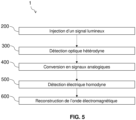
A cet effet, l'invention porte sur un procédé de reconstruction d'une onde électromagnétique vectorielle rétrodiffusée dans tout ou partie d'une fibre optique, ledit procédé comprenant :
- Une étape d'injection dans la fibre optique d'un signal lumineux de fréquence v0 ou v0 + vA,
- Une étape de détection optique hétérodyne résolue en polarisation comportant la génération, par un moyen de séparation optique et à partir d'une rétrodiffusion du signal lumineux injecté et d'une onde électromagnétique provenant d'un oscillateur local, d'au moins deux signaux lumineux rétrodiffusés de polarisation orthogonale, produisant un battement de préférence de fréquence vA,
- Une étape de conversion, par au moins un, de préférence au moins deux, photo-détecteurs, des signaux lumineux rétrodiffusés de polarisation orthogonale en signaux analogiques initiaux,
- Une étape de détection électrique homodyne, par un démodulateur IQ, permettant une démodulation de type IQ sur chacun des signaux analogiques initiaux, de façon à générer des signaux analogiques démodulés I et Q pour chacun des signaux lumineux rétrodiffusés de polarisation orthogonale, et
- Une étape de reconstruction, par un module de traitement, de l'onde électromagnétique vectorielle rétrodiffusée dans tout ou partie de la fibre optique à partir des signaux analogiques démodulés I et Q générés.
- A step of injecting into the optical fiber a light signal of frequency v 0 or v 0 + v A ,
- A polarization-resolved heterodyne optical detection step comprising the generation, by an optical separation means and from a backscatter of the injected light signal and an electromagnetic wave originating from a local oscillator, of at least two light signals backscattered with orthogonal polarization, producing a preference beat of frequency v A ,
- A conversion step, by at least one, preferably at least two, photo-detectors, of the backscattered light signals of orthogonal polarization into initial analog signals,
- A step of homodyne electrical detection, by an IQ demodulator, allowing an IQ type demodulation on each of the initial analog signals, so as to generate demodulated analog signals I and Q for each of the backscattered light signals of orthogonal polarization, and
- A step of reconstruction, by a processing module, of the vector electromagnetic wave backscattered in all or part of the optical fiber from the demodulated analog signals I and Q generated.
Un tel procédé permet de reconstruire une onde électromagnétique vectorielle rétrodiffusée et ainsi donner un accès complet, simultané et en temps réel aux propriétés qui la caractérisent (amplitude, phase, état et degrés de polarisation, dynamique vectorielle). Les caractéristiques d'une telle onde électromagnétique vectorielle rétrodiffusée peuvent ensuite être analysées pour caractériser au mieux son milieu de propagation à savoir les variations d'indice, de chemin optique, de biréfringence, de dispersion modale de polarisation, et cela de façon répartie dans tout ou partie de la fibre optique. En outre, un tel procédé permet de mitiger le phénomène de fading. Le procédé permet également de faciliter l'analyse des mesures réparties par fibre optique et présente l'avantage d'être peu coûteux. En outre, aucun critère de sélectivité n'est appliqué, l'information de phase est conservée permettant ainsi de l'exploiter.Such a process makes it possible to reconstruct a backscattered vector electromagnetic wave and thus give complete, simultaneous and real-time access to the properties that characterize it. (amplitude, phase, state and degrees of polarization, vector dynamics). The characteristics of such a backscattered vector electromagnetic wave can then be analyzed to best characterize its propagation medium, namely the variations in index, optical path, birefringence, polarization modal dispersion, and this in a distributed manner throughout or part of the optical fiber. In addition, such a method makes it possible to mitigate the phenomenon of fading. The method also makes it possible to facilitate the analysis of the measurements distributed by optical fiber and has the advantage of being inexpensive. In addition, no selectivity criterion is applied, the phase information is retained, thus making it possible to exploit it.
Ainsi, le procédé permet une reconstruction et une analyse précise sans avoir besoin d'échantillonner fortement ou de disposer d'une forte puissance de calcul.Thus, the method allows a reconstruction and an accurate analysis without the need to sample heavily or to have a high computing power.
L'utilisation d'un oscillateur local identique pour la détection optique hétérodyne et d'un signal de référence identique pour la démodulation électrique IQ permet de traiter de manière synchronisée dans le temps, en parallèle et de façon combinée les deux polarisations orthogonales. Leur relation est en tout point préservée.The use of an identical local oscillator for heterodyne optical detection and of an identical reference signal for IQ electrical demodulation makes it possible to process the two orthogonal polarizations in a time-synchronized manner, in parallel and in a combined manner. Their relationship is in all respects preserved.
- il comprend une étape de déphasage d'une partie des signaux lumineux rétrodiffusés, d'une partie des signaux analogiques initiaux ou d'un signal analogique de référence à la fréquence vA. Ceci permet de réduire le bruit et d'améliorer la qualité des mesures. En outre, ceci permet d'accéder à l'amplitude complexe ou à la phase et à l'amplitude.it comprises a step of phase shifting a part of the backscattered light signals, a part of the initial analog signals or a reference analog signal at the frequency v A . This reduces noise and improves the quality of the measurements. Also, this provides access to complex amplitude or phase and amplitude.
- l'étape de détection électrique homodyne comprend une démodulation à la fréquence vA par le démodulateur IQ. La détection électrique homodyne permet une démodulation de type IQ. La démodulation électrique IQ à la fréquence vA permet de réduire le bruit et d'améliorer la qualité des mesures tout en accédant de façon directe à l'amplitude complexe des signaux démodulés et à en faire une acquisition à un taux d'échantillonnage réduit.the homodyne electrical detection step comprises demodulation at the frequency v A by the demodulator IQ. Electrical homodyne detection allows IQ-type demodulation. Electrical demodulation IQ at frequency v A makes it possible to reduce noise and improve the quality of measurements while directly accessing the complex amplitude of the demodulated signals and acquiring them at a reduced sampling rate.
- il comprend une étape de calcul d'amplitude complexe à partir des signaux analogiques démodulés I et Q générés.it comprises a step of complex amplitude calculation from the demodulated analog signals I and Q generated.
- l'étape de reconstruction de l'onde électromagnétique vectorielle rétrodiffusée comprend une étape de calcul de phase et/ou d'amplitude dans tout ou partie de la fibre optique et pour tout axe de projection dans tout ou partie de la fibre optique en fonction des valeurs d'amplitudes complexes déterminées à partir des signaux analogiques démodulés I et Q générés. La réalisation de cette sous-étape de calcul donne ensuite la possibilité de rapidement reconstruire l'onde électromagnétique vectorielle rétrodiffusée.the step of reconstructing the backscattered vector electromagnetic wave comprises a phase and/or amplitude calculation step in all or part of the optical fiber and for any axis of projection in all or part of the optical fiber according to the complex amplitude values determined from the generated I and Q demodulated analog signals. There carrying out this calculation sub-step then gives the possibility of rapidly reconstructing the backscattered vector electromagnetic wave.
- il comprend une étape de calcul de valeurs de phase et d'amplitude à partir des signaux analogiques démodulés I et Q générés.it comprises a step of calculating phase and amplitude values from the demodulated analog signals I and Q generated.
- l'étape de reconstruction de l'onde électromagnétique vectorielle rétrodiffusée comprend une étape de calcul d'amplitude complexe dans tout ou partie de la fibre optique et pour tout axe de projection dans tout ou partie de la fibre optique en fonction des valeurs d'amplitude et de phase calculées à partir des signaux analogiques démodulés I et Q générés.the step of reconstructing the backscattered vector electromagnetic wave includes a step of complex amplitude calculation in all or part of the optical fiber and for any axis of projection in all or part of the optical fiber as a function of the amplitude values and phase calculated from the demodulated analog signals I and Q generated.
- il comprend le calcul d'une amplitude maximale comprenant l'identification d'un angle optimal associé à l'amplitude maximale pour tout axe de projection dans tout ou partie de la fibre optique, ledit angle optimal correspondant à l'angle présentant l'amplitude maximale la plus élevée parmi des amplitudes d'une pluralité d'angles correspondant aux axes de projection dans tout ou partie de la fibre optique. La réalisation de cette sous-étape de calcul donne ensuite la possibilité de rapidement reconstruire l'onde électromagnétique vectorielle rétrodiffusée. En outre, ceci permet d'accéder à un ou plusieurs paramètres d'intérêt de l'onde électromagnétique vectorielle rétrodiffusée.it comprises the calculation of a maximum amplitude comprising the identification of an optimum angle associated with the maximum amplitude for any axis of projection in all or part of the optical fiber, said optimum angle corresponding to the angle having the amplitude highest maximum among amplitudes of a plurality of angles corresponding to the projection axes in all or part of the optical fiber. Performing this calculation sub-step then gives the possibility of rapidly reconstructing the backscattered vector electromagnetic wave. Furthermore, this makes it possible to access one or more parameters of interest of the backscattered vector electromagnetic wave.
- il comprend une étape de détection d'un paramètre d'intérêt, de préférence de l'onde électromagnétique vectorielle rétrodiffusée. Ceci permet de pouvoir caractériser l'onde électromagnétique vectorielle rétrodiffusée. En outre, ceci permet également de pouvoir caractériser les influences environnementales pouvant s'exercer sur la fibre optique.it comprises a step of detecting a parameter of interest, preferably the backscattered vector electromagnetic wave. This makes it possible to characterize the backscattered vector electromagnetic wave. In addition, this also makes it possible to be able to characterize the environmental influences that may be exerted on the optical fiber.
- l'étape de reconstruction de l'onde électromagnétique vectorielle rétrodiffusée comprend une étape de calcul, en une pluralité de points de tout ou partie de la fibre optique, de l'amplitude du signal pour une pluralité d'angles. Ceci permet d'accéder en une pluralité de points de la fibre optique à l'amplitude maximale du signal, l'amplitude maximale permettant d'accéder à des informations peu ou pas affectée par les phénomènes de fading. Plus largement une telle étape permet d'accéder à l'état de polarisation.the step of reconstructing the backscattered vector electromagnetic wave comprises a step of calculating, at a plurality of points on all or part of the optical fiber, the amplitude of the signal for a plurality of angles. This allows access at a plurality of points of the optical fiber to the maximum amplitude of the signal, the maximum amplitude allowing access to information little or not affected by the phenomena of fading. More broadly, such a step provides access to the polarization state.
- il comprend une étape d'identification d'un axe principal optique du signal lumineux rétrodiffusé dans tout ou partie de la fibre optique à partir d'un calcul d'amplitude maximale, de préférence de l'amplitude du signal calculé pour une pluralité d'angles. Ceci permet l'accès à l'axe principal optique et donc permet d'atténuer l'effet de fading. En effet, l'axe principal optique du signal lumineux rétrodiffusé dans tout ou partie de la fibre optique correspond aux axes permettant une amplitude maximale du signal pour une pluralité de points de tout ou partie de la fibre optique. En projetant l'amplitude complexe sur l'axe principal, l'effet de fading induit par polarisation est supprimé tout en préservant l'information de phase.it comprises a step of identifying a main optical axis of the backscattered light signal in all or part of the optical fiber from a calculation of maximum amplitude, preferably of the amplitude of the signal calculated for a plurality of angles. This allows access to the main optical axis and therefore makes it possible to attenuate the fading effect. Indeed, the main optical axis of the signal backscattered light in all or part of the optical fiber corresponds to the axes allowing a maximum amplitude of the signal for a plurality of points of all or part of the optical fiber. By projecting the complex amplitude onto the main axis, the bias-induced fading effect is suppressed while preserving the phase information.
- il comprend une étape de modulation du signal lumineux par un modulateur, avant l'étape d'injection dans la fibre optique, ladite modulation permettant un décalage de la fréquence du signal lumineux d'une valeur égale à vA. Ceci permet de différencier les différents signaux issus de la rétrodiffusion ou de l'oscillateur local.it comprises a step of modulating the light signal by a modulator, before the step of injecting it into the optical fiber, said modulation allowing a shift in the frequency of the light signal by a value equal to v A . This makes it possible to differentiate the different signals coming from the backscatter or from the local oscillator.
- il comprend une étape d'amplification intermédiaire du signal électrique issu du modulateur à la fréquence de modulation vA, par exemple par un amplificateur. Ceci permet d'améliorer la sensibilité du résultat.it comprises a step of intermediate amplification of the electric signal coming from the modulator at the modulation frequency v A , for example by an amplifier. This improves the sensitivity of the result.
- il comprend une étape de filtrage analogique, par exemple par au moins un filtre passe bas, permettant de supprimer les fréquences des signaux analogiques supérieures à un seuil prédéterminé. Ceci permet de diminuer le bruit présent autour de la fréquence vA.it comprises an analog filtering step, for example by at least one low-pass filter, making it possible to suppress the frequencies of the analog signals above a predetermined threshold. This makes it possible to reduce the noise present around the frequency v A .
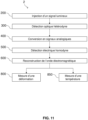
Selon un autre aspect, l'invention se rapporte à un procédé de mesure optoélectronique dans un système de détection acoustique distribuée comprenant une reconstruction d'une onde électromagnétique vectorielle rétrodiffusée dans tout ou partie d'une fibre optique selon l'invention et une mesure d'une déformation et/ou d'une variation de température dans tout ou partie de la fibre optique en fonction de l'onde électromagnétique vectorielle rétrodiffusée reconstruite. Ceci permet un accès aux informations liées aux influences environnementales de la fibre et cela de façon diverse. En effet, grâce à l'invention, n'importe quelle contrainte, déformation ou variation de température mais également de pression par exemple peut être détectée et analysée. According to another aspect, the invention relates to an optoelectronic measurement method in a distributed acoustic detection system comprising a reconstruction of a vector electromagnetic wave backscattered in all or part of an optical fiber according to the invention and a measurement of a deformation and/or a temperature variation in all or part of the optical fiber as a function of the reconstructed backscattered vector electromagnetic wave. This allows access to information related to the environmental influences of the fiber and this in various ways. Indeed, thanks to the invention, any stress, deformation or variation of temperature but also of pressure for example can be detected and analyzed.
Selon d'autres caractéristiques optionnelles du procédé, il comprend une mesure d'une déformation et/ou d'une variation de température dans tout ou partie de la fibre optique sur un axe principal optique de préférence reconstruit.According to other optional characteristics of the method, it comprises a measurement of a deformation and/or of a temperature variation in all or part of the optical fiber on a principal optical axis which is preferably reconstructed.
Selon un autre aspect, l'invention concerne un dispositif de reconstruction d'une onde électromagnétique vectorielle rétrodiffusée dans tout ou partie d'une fibre optique, ledit dispositif comprenant :
- Une source lumineuse configurée pour générer un signal lumineux de fréquence v0, apte à être injecté dans la fibre optique,
- Un moyen de séparation optique configuré pour générer au moins deux signaux lumineux rétrodiffusés de polarisation orthogonale, produisant un battement de préférence de fréquence vA, à partir d'une rétrodiffusion du signal lumineux injecté et d'une onde électromagnétique provenant d'un oscillateur local,
- Au moins un, de préférence au moins deux photo-détecteurs, configurés pour convertir les signaux lumineux rétrodiffusés de polarisation orthogonale en signaux analogiques initiaux,
- Un démodulateur IQ agencé pour réaliser une détection électrique homodyne, permettant une démodulation de type IQ sur chacun des signaux analogiques initiaux de façon à générer des signaux analogiques démodulés I et Q pour chacun des signaux lumineux rétrodiffusés de polarisation orthogonale, et
- Un module de traitement configuré pour reconstruire l'onde électromagnétique vectorielle rétrodiffusée dans tout ou partie de la fibre optique à partir des signaux analogiques démodulés I et Q générés.
- A light source configured to generate a light signal of frequency v 0 , capable of being injected into the optical fiber,
- An optical separation means configured to generate at least two backscattered light signals of orthogonal polarization, producing a preferably beat of frequency v A , from a backscatter of the injected light signal and an electromagnetic wave coming from a local oscillator ,
- At least one, preferably at least two photo-detectors, configured to convert the backscattered light signals of orthogonal polarization into initial analog signals,
- An IQ demodulator arranged to perform homodyne electrical detection, allowing IQ type demodulation on each of the initial analog signals so as to generate demodulated analog signals I and Q for each of the backscattered light signals of orthogonal polarization, and
- A processing module configured to reconstruct the vector electromagnetic wave backscattered in all or part of the optical fiber from the demodulated I and Q analog signals generated.
Un tel dispositif selon l'invention permet de reconstruire pleinement l'onde électromagnétique rétrodiffusée dans une fibre optique lorsqu'une impulsion y est injectée. Le moyen de séparation optique est avantageusement configuré pour réaliser une détection optique hétérodyne résolue en polarisation. Le dispositif permettant la reconstruction d'une onde électromagnétique extrait de façon simultanée l'amplitude complexe ou l'amplitude et la phase pour deux polarisations orthogonales de l'onde électromagnétique rétrodiffusée. L'accès à l'onde électromagnétique vectorielle permet de disposer de toutes ses caractéristiques et donc ouvre des voies d'analyses du signal rétrodiffusé jusqu'alors inaccessibles. En particulier, en reconstruisant l'onde électromagnétique rétrodiffusée, l'effet de fading induit par la polarisation peut-être totalement supprimée et surtout l'information de phase est préservée, permettant ainsi de l'exploiter. Les amplitudes complexes acquises par le dispositif contenant les informations d'amplitude et de phase des deux polarisations orthogonales acquises par le dispositif sont combinées et non traitées séparément pour fournir une information de phase et d'amplitude de l'onde où l'effet de fading induit par polarisation est supprimé. Ainsi, aucun critère de sélectivité n'est imposé, l'atténuation du phénomène de fading repose entièrement sur les propriétés physiques de l'onde électromagnétique guidée dans la fibre optique. En outre, le dispositif présente l'avantage d'être moins complexe que les systèmes utilisant une diversité en fréquence optique pour atténuer l'effet de fading.Such a device according to the invention makes it possible to fully reconstruct the electromagnetic wave backscattered in an optical fiber when a pulse is injected therein. The optical separation means is advantageously configured to perform polarization-resolved heterodyne optical detection. The device allowing the reconstruction of an electromagnetic wave simultaneously extracts the complex amplitude or the amplitude and the phase for two orthogonal polarizations of the backscattered electromagnetic wave. Access to the vectorial electromagnetic wave makes it possible to have all of its characteristics and therefore opens up ways of analyzing the backscattered signal that were previously inaccessible. In particular, by reconstructing the backscattered electromagnetic wave, the fading effect induced by the polarization can be totally suppressed and above all the phase information is preserved, thus making it possible to exploit it. The complex amplitudes acquired by the device containing the amplitude and phase information of the two orthogonal polarizations acquired by the device are combined and not processed separately to provide phase and amplitude information of the wave where the fading effect polarization induced is suppressed. Thus, no selectivity criterion is imposed, the attenuation of the fading phenomenon relies entirely on the physical properties of the electromagnetic wave guided in the optical fiber. In addition, the device has the advantage of being less complex than systems using optical frequency diversity to attenuate the fading effect.
D'autres avantages et caractéristiques de l'invention apparaitront à la lecture de la description suivante donnée à titre d'exemple illustratif et non limitatif, en référence aux Figures annexées :
- [
Fig 1 ] représente un schéma d'un dispositif selon l'art antérieur d'un système de mesure répartie basé sur la rétrodiffusion Rayleigh utilisant une détection optique hétérodyne résolue en polarisation et une analyse numérique de l'amplitude et de la phase. - [
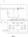
Fig 2 ] représente un schéma d'un dispositif selon un mode de réalisation de l'invention. - [
Fig 3 ] représente un schéma d'un dispositif selon un mode de réalisation de l'invention. - [
Fig 4 ] représente un schéma d'un dispositif selon un mode de réalisation de l'invention. - [
Fig 5 ] représente un schéma d'un procédé selon un mode de réalisation de l'invention. - [
Fig 6 ] représente un schéma d'un procédé selon un mode de réalisation de l'invention. - [
Fig 7 ] représente un schéma d'un mode de réalisation d'une détection électrique homodyne selon l'invention. - [
Fig 8 ] représente un schéma d'une étape de reconstruction de l'onde électromagnétique vectorielle selon un mode de réalisation de l'invention. - [
Fig 9 ] représente un schéma d'un exemple d'une onde électromagnétique vectorielle rétrodiffusée reconstruite. - [
Fig 10 ] représente la variation de l'angle de l'axe principal de l'onde électromagnétique rétrodiffusée en fonction de la distance de la fibre optique lors de la propagation d'une impulsion dans ladite fibre optique. - [
Fig 11 ] représente un schéma d'un procédé de mesure optoélectronique selon un mode de réalisation de l'invention. - [
Fig 12 ] représente une comparaison d'étapes de calcul de l'amplitude et de la phase en fonction de différents modes de réalisation de l'invention (A, B) en comparaison à l'état de la technique (C). - [
Fig 13 ] représente un schéma illustrant une amélioration de la qualité du signal obtenu lors de l'utilisation de l'axe principale optique selon un procédé de l'invention en comparaison à l'utilisation d'un axe fixe selon l'art antérieur.
- [
Fig 1 ] shows a diagram of a device according to the prior art of a distributed measurement system based on Rayleigh backscattering using polarization-resolved heterodyne optical detection and digital analysis of the amplitude and the phase. - [
Fig 2 ] shows a diagram of a device according to one embodiment of the invention. - [
Fig.3 ] shows a diagram of a device according to one embodiment of the invention. - [
Fig 4 ] shows a diagram of a device according to one embodiment of the invention. - [
Fig.5 ] shows a diagram of a method according to one embodiment of the invention. - [
Fig 6 ] shows a diagram of a method according to one embodiment of the invention. - [
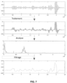
Fig 7 ] represents a diagram of an embodiment of a homodyne electrical detection according to the invention. - [
Fig.8 ] represents a diagram of a reconstruction step of the vector electromagnetic wave according to an embodiment of the invention. - [
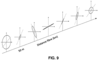
Fig.9 ] shows a diagram of an example of a reconstructed backscattered vector electromagnetic wave. - [
Fig. 10 ] represents the variation of the angle of the main axis of the backscattered electromagnetic wave as a function of the distance from the optical fiber during the propagation of a pulse in said optical fiber. - [
Fig.11 ] represents a diagram of an optoelectronic measurement method according to one embodiment of the invention. - [
Fig. 12 ] shows a comparison of amplitude and phase calculation steps according to different embodiments of the invention (A, B) in comparison to the state of the art (C). - [
Fig. 13 ] represents a diagram illustrating an improvement in the quality of the signal obtained during the use of the main optical axis according to a method of the invention in comparison with the use of a fixed axis according to the prior art.
Des aspects de la présente invention sont décrits en référence à des organigrammes et / ou à des schémas fonctionnels de procédés, d'appareils (systèmes) selon des modes de réalisation de l'invention.Aspects of the present invention are described with reference to flow charts and/or block diagrams of methods, apparatus (systems) according to embodiments of the invention.
Sur les figures, les organigrammes et les schémas fonctionnels illustrent l'architecture, la fonctionnalité et le fonctionnement d'implémentations possibles de systèmes, de procédés selon divers modes de réalisation de la présente invention. A cet égard, chaque bloc dans les organigrammes ou blocs-diagrammes peut représenter un système, un dispositif, un module ou un code, qui comprend une ou plusieurs instructions exécutables pour mettre en oeuvre la ou les fonctions logiques spécifiées. Dans certaines implémentations, les fonctions associées aux blocs peuvent apparaître dans un ordre différent que celui indiqué sur les figures. Par exemple, deux blocs montrés successivement peuvent, en fait, être exécutés sensiblement simultanément, ou les blocs peuvent parfois être exécutés dans l'ordre inverse, en fonction de la fonctionnalité impliquée. Chaque bloc des schémas de principe et / ou de l'organigramme, et des combinaisons de blocs dans les schémas de principe et / ou l'organigramme, peuvent être mis en oeuvre par des systèmes matériels spéciaux qui exécutent les fonctions ou actes spécifiés ou effectuer des combinaisons de matériel spécial et d'instructions informatiques.In the figures, flowcharts and block diagrams illustrate the architecture, functionality and operation of possible implementations of systems, methods according to various embodiments of the present invention. In this regard, each block in the flowcharts or block diagrams may represent a system, device, module, or code, which includes one or more executable instructions to implement the specified logical function(s). In some implementations, the functions associated with the blocks may appear in a different order than that shown in the figures. For example, two blocks shown in succession may, in fact, be executed substantially simultaneously, or the blocks may sometimes be executed in reverse order, depending on the functionality involved. Each block in the block diagrams and/or flowchart, and combinations of blocks in the block diagrams and/or flowchart, may be implemented by special hardware systems that perform the specified functions or acts or perform combinations of special equipment and computer instructions.
Par ailleurs, les blocs en pointillés correspondent à des étapes optionnelles.Furthermore, the dotted blocks correspond to optional steps.
Dans la suite de la description, l'expression « onde électromagnétique vectorielle rétrodiffusée » au sens de l'invention correspond à l'onde électromagnétique rétrodiffusée par un matériau dans lequel elle se propage telle qu'une fibre optique définit par le comportement spatial et temporel de son champ électrique (son orientation spatiale, son amplitude et sa phase).In the rest of the description, the expression "backscattered vector electromagnetic wave " within the meaning of the invention corresponds to the electromagnetic wave backscattered by a material in which it propagates such as an optical fiber defined by the spatial and temporal behavior its electric field (its spatial orientation, its amplitude and its phase).
Le terme « reconstruction » au sens de l'invention correspond au calcul des caractéristiques d'amplitude et de phase de l'onde électromagnétique vectorielle rétrodiffusée quel que soit l'axe de polarisation et de préférence pour tout axe de polarisation.The term “ reconstruction ” within the meaning of the invention corresponds to the calculation of the amplitude and phase characteristics of the backscattered vector electromagnetic wave whatever the polarization axis and preferably for any polarization axis.
On entend par « dans tout ou partie » au sens de l'invention, une partie de la fibre optique ou l'ensemble de la fibre optique. Ainsi, dans le cadre de mesures réparties, celle-ci peuvent être réparties tout au long de la fibre optique ou sur une ou plusieurs portions de la fibre optique mais également il peut s'agir de mesure répartie sur une pluralité de points au sein de la fibre optique. De préférence, cela ne concerne pas une mesure ponctuelle.The term " in whole or in part " within the meaning of the invention, part of the optical fiber or all of the optical fiber. Thus, in the context of distributed measurements, these may be distributed all along the optical fiber or over one or more portions of the optical fiber, but also it may be a question of measurement distributed over a plurality of points within the optical fiber. Preferably, this does not concern a one-off measurement.
On entend par « signal lumineux » au sens de l'invention une onde électromagnétique de fréquence fixe ou variable, d'intensité fixe ou variable, libre ou guidée. De préférence il s'agit d'un signal guidé dans une fibre optique.By “ light signal ” is meant in the sense of the invention an electromagnetic wave of fixed or variable frequency, of fixed or variable intensity, free or guided. Preferably it is a signal guided in an optical fiber.
Le terme « injection » au sens de l'invention correspond à l'introduction d'un signal lumineux dans une fibre optique par exemple.The term “ injection ” within the meaning of the invention corresponds to the introduction of a light signal into an optical fiber for example.
Le terme « rétrodiffusé » ou « rétrodiffusion » au sens de l'invention correspond à la fraction de l'onde incidente qui est retournée dans la direction d'émission de l'onde incidente. Il s'agit d'une diffusion arrière d'une particule, d'une déflexion du rayonnement due à la diffusion par la matière suivant des angles supérieurs à 90° par rapport à leur direction d'émission.The term “ backscattered ” or “ backscatter ” within the meaning of the invention corresponds to the fraction of the incident wave which is returned in the direction of emission of the incident wave. It is a rear scattering of a particle, a deflection of the radiation due to the scattering by matter at angles greater than 90° with respect to their direction of emission.
On entend par « signaux lumineux de polarisation orthogonale » au sens de l'invention, des signaux lumineux pour lesquels le produit scalaire des deux vecteurs de JONES représentant l'état de polarisation de ces signaux lumineux est égale à zéro, autrement dit des signaux lumineux dont l'état de polarisation représenté respectivement par deux vecteur E1 et E2 sont polarisé orthogonalement si E1*. E2 = 0, où * est l'opérateur de transposée conjuguée.The term “ light signals of orthogonal polarization ” within the meaning of the invention means light signals for which the scalar product of the two JONES vectors representing the state of polarization of these light signals is equal to zero, in other words light signals whose state of polarization represented respectively by two vectors E1 and E2 are orthogonally polarized if E1*. E2 = 0, where * is the conjugate transpose operator.
Le terme « signal analogique » au sens de l'invention correspond à un signal présentant une grandeur physique et variant de façon continue. Par exemple, lors de la conversion d'un signal optique en un signal électrique, ledit signal électrique est alors un signal analogique.The term “ analog signal ” within the meaning of the invention corresponds to a signal having a physical quantity and varying continuously. For example, when converting an optical signal into an electrical signal, said electrical signal is then an analog signal.
On entend par « signal numérique » au sens de l'invention notamment un ensemble de grandeurs physiques ou de données représentées au moyen de caractères chiffrés au moyen duquel les informations sont représentées par un nombre fini de valeurs discrètes bien déterminées qu'une de ses caractéristiques peut prendre dans le temps.The term " digital signal " within the meaning of the invention in particular means a set of physical quantities or data represented by means of encrypted characters by means of which the information is represented by a finite number of well-determined discrete values that one of its characteristics may take time.
On entend par «une partie des signal » une fraction de l'ensemble du signal, par exemple la moitié du signal.The term “part of the signal” means a fraction of the whole of the signal, for example half of the signal.
Le terme « détection homodyne » au sens de l'invention correspond à une détection permettant d'extraire les caractéristiques telles que l'amplitude et la phase d'un signal oscillant à une certaine fréquence par comparaison avec une oscillation de référence de même fréquence. La comparaison se fait généralement par multiplication avec un oscillateur local présentant une forme identique à la forme du signal oscillant. Le signal est ainsi amené en bande de base (fréquence nulle). En général, homodyne correspondant à une fréquence unique par opposition aux doubles fréquences (détection hétérodyne).The term " homodyne detection " within the meaning of the invention corresponds to a detection making it possible to extract the characteristics such as the amplitude and the phase of a signal oscillating at a certain frequency by comparison with a reference oscillation of the same frequency. The comparison is generally done by multiplication with a local oscillator having a shape identical to the shape of the oscillating signal. The signal is thus brought to baseband (zero frequency). In general, homodyne corresponding to a single frequency as opposed to dual frequencies (heterodyne detection).
Le terme « détection hétérodyne » au sens de l'invention correspond à une détection qui repose sur le mélange du signal lumineux rétrodiffusé avec un signal lumineux de référence par exemple le signal lumineux d'un oscillateur local. La détection hétérodyne permet de décaler en fréquence le spectre fréquentiel composant un signal. La détection hétérodyne permet, par exemple, de ramener un signal à haute fréquence vers une fréquence plus faible. Pour amener un signal a plus faible fréquence, ce signal peut être mélangé à un signal connu d'un oscillateur local, la fréquence obtenue est alors la différence entre oscillateur local et signal étudié.The term “ heterodyne detection ” within the meaning of the invention corresponds to a detection which is based on the mixing of the backscattered light signal with a reference light signal, for example the light signal of a local oscillator. Heterodyne detection makes it possible to shift the frequency spectrum of a signal in frequency. Heterodyne detection makes it possible, for example, to reduce a high frequency signal to a lower frequency. To bring a signal to a lower frequency, this signal can be mixed with a signal known from a local oscillator, the frequency obtained is then the difference between the local oscillator and the studied signal.
On entend par « modulation » au sens de l'invention l'action de faire varier un signal pour en modifier son amplitude, sa phase, sa fréquence dans le tempsBy “ modulation ” is meant within the meaning of the invention the action of varying a signal in order to modify its amplitude, its phase, its frequency over time.
Le terme « démodulation » au sens de l'invention correspond à une méthode d'analyse d'un signal initial permettant de séparer un signal d'intérêt de l'oscillation qu'il module. Une démodulation est dite « de type IQ » lorsqu'elle comporte une démodulation en phase et une démodulation en quadrature de phase.The term “ demodulation ” within the meaning of the invention corresponds to a method of analyzing an initial signal making it possible to separate a signal of interest from the oscillation that it modulates. A demodulation is said to be of “IQ type” when it includes in-phase demodulation and quadrature-phase demodulation.
L'expression « amplitude complexe » au sens de l'invention correspond à l'amplitude d'un signal telle que composée d'une partie réelle et d'une partie imaginaire.The expression “ complex amplitude ” within the meaning of the invention corresponds to the amplitude of a signal as composed of a real part and an imaginary part.
L'expression « partie réelle et imaginaire » au sens de l'invention correspond à chaque partie d'un signal complexe. Il s'agit d'une représentation dans un plan complexe, où la partie réelle est projetée sur l'axe des réels et la partie imaginaire sur l'axe imaginaire, l'argument correspondant alors à la phase et le module à l'amplitude. L'utilisation d'un signal complexe permet de simplifier les calculs.The expression “ real and imaginary part ” within the meaning of the invention corresponds to each part of a complex signal. It is a representation in a complex plane, where the real part is projected on the real axis and the imaginary part on the imaginary axis, the argument then corresponding to the phase and the modulus to the amplitude . The use of a complex signal makes it possible to simplify the calculations.
On entend par « déphasage », la différence de phase à l'origine des signaux étudiés. Le déphasage est généralement compris en π et -π et assimilé à un retard de la variation d'un signal par rapport à un autre, à la même fréquence.“ Phase shift ” means the phase difference at the origin of the signals studied. The phase shift is generally understood in π and -π and assimilated to a delay in the variation of one signal relative to another, at the same frequency.
L'expression « multiplié en phase » au sens de l'invention correspond au mélange du signal issu d'un modulateur avec le signal analogique.The expression " multiplied in phase " within the meaning of the invention corresponds to the mixing of the signal coming from a modulator with the analog signal.
L'expression « multiplié en quadrature de phase » au sens de l'invention correspond, en opposition à « multiplié en phase », au mélange du signal issu d'un modulateur avec le signal analogique, le rapport de phase entre les deux étant seulement déphasé de 90° ou pi/2 radian par rapport à la « multiplication en phase ».The expression " multiplied in phase quadrature " within the meaning of the invention corresponds, as opposed to "multiplied in phase", to the mixing of the signal from a modulator with the analog signal, the phase ratio between the two being only out of phase by 90° or pi/2 radian with respect to the "in-phase multiplication".
L'expression « seuil prédéterminé » au sens de l'invention correspond à une valeur déterminée au-dessus ou au-dessous de laquelle les fréquences sont filtrées. Il s'agit d'une valeur limite et correspond généralement à une valeur de fréquence au-delà de laquelle un maximum de bruit est enlevé tout en préservant le signal d'intérêt.The expression “ predetermined threshold ” within the meaning of the invention corresponds to a determined value above or below which the frequencies are filtered. It's about a limit value and generally corresponds to a frequency value beyond which a maximum of noise is removed while preserving the signal of interest.
On entend par « contrainte » au sens de l'invention une force appliquée sur un matériau ou un corps. Cette force peut être exercée par une torsion, une traction, une poussée ou toute autre force entrainant une « déformation » ou un déplacement du matériau ou du corps sur lequel elle s'exerce.The term “ constraint ” in the sense of the invention means a force applied to a material or a body. This force can be exerted by a torsion, a traction, a push or any other force resulting in a “ deformation ” or a displacement of the material or the body on which it is exerted.
Le terme « déformation » au sens de l'invention correspond à un changement de forme ou de dimension d'un matériau ou d'un corps sans dépasser la limite de rupture du matériau ou du corps en question. Par exemple, une déformation au sens de l'invention tend à étirer ou comprimer un matériau ou un corps subissant une force et notamment sous forme d'une contrainte.The term “ deformation ” within the meaning of the invention corresponds to a change in shape or dimension of a material or of a body without exceeding the breaking limit of the material or of the body in question. For example, a deformation within the meaning of the invention tends to stretch or compress a material or a body undergoing a force and in particular in the form of a constraint.
L'expression « axe principal optique » au sens de l'invention correspond à l'axe optique sur lequel l'amplitude de la projection de l'onde électromagnétique est maximale à l'intérieur d'une fibre optique. L'axe principal est celui sur lequel le signal présente une amplitude maximale, c'est-à-dire supérieure à l'ensemble des autres amplitudes du signal sur une même tranche de fibre optique. C'est l'axe principal de l'ellipse formé par le champ électrique de l'onde électromagnétique à une position donnée de la fibre, l'ellipse définissant l'état de polarisation de l'onde électromagnétique. Ainsi, au sens de l'invention, l'axe principal optique varie tout au long de la fibre optique pour toujours correspondre à l'axe sur lequel le signal, en ce point de la fibre optique, présentera une amplitude maximale.The expression “ main optical axis ” within the meaning of the invention corresponds to the optical axis on which the amplitude of the projection of the electromagnetic wave is maximum inside an optical fiber. The main axis is that on which the signal has a maximum amplitude, that is to say greater than all the other amplitudes of the signal on the same optical fiber slice. It is the main axis of the ellipse formed by the electric field of the electromagnetic wave at a given position of the fiber, the ellipse defining the state of polarization of the electromagnetic wave. Thus, within the meaning of the invention, the main optical axis varies throughout the optical fiber to always correspond to the axis on which the signal, at this point of the optical fiber, will present a maximum amplitude.
L'expression « axe de projection » au sens de l'invention correspond à l'axe sur lequel le champ électrique va osciller, c'est-à-dire, où il est possible d'observer le champ électrique osciller.The expression " projection axis " within the meaning of the invention corresponds to the axis on which the electric field will oscillate, that is to say, where it is possible to observe the electric field oscillate.
On entend par « état de polarisation » au sens de l'invention, la forme définie par le mouvement de l'orientation du champ électrique dans le plan de section perpendiculaire à la propagation de l'onde électromagnétique. L'état de polarisation peut-être alors rectiligne, ellipsoïdal ou circulaire.The term "state of polarization " within the meaning of the invention, the form defined by the movement of the orientation of the electric field in the plane of section perpendicular to the propagation of the electromagnetic wave. The state of polarization can then be rectilinear, ellipsoidal or circular.
On entend par « détection d'un paramètre » ou par « paramètres d'intérêt » au sens de l'invention, une ou plusieurs caractéristiques de l'onde électromagnétique vectorielle rétrodiffusée telles que amplitude, phase, état et degrés de polarisation, dynamique vectorielle, variations d'indice, de chemin optique, de biréfringence, de dispersion modale de polarisation.The term “ detection of a parameter ” or “ parameters of interest ” within the meaning of the invention means one or more characteristics of the backscattered vector electromagnetic wave such as amplitude, phase, state and degrees of polarization, vector dynamics , variations in index, optical path, birefringence, polarization mode dispersion.
On entend par « couplé » au sens de l'invention, mélanger par exemple additionner ou multiplier deux signaux entre eux.By “ coupled ” is meant in the sense of the invention, mixing, for example adding or multiplying two signals together.
Dans la suite de la description, les mêmes références sont utilisées pour désigner les mêmes éléments.In the remainder of the description, the same references are used to designate the same elements.
Divers effets optiques sont connus lors d'une mesure par fibre optique notamment la rétrodiffusion Brillouin, Raman et Rayleigh, et chacune de ces techniques présente des caractéristiques différentes permettant de déterminer différentes influences environnementales, à différentes échelles de temps. Les paramètres environnementaux de la fibre optique mesurables en utilisant une technique de mesure repartie par fibre optique basée sur la rétrodiffusion sont reliés aux comportements de l'onde électromagnétique vectorielle rétrodiffusée. Par ailleurs, les paramètres environnementaux de la fibre optique actuellement mesurables en utilisant une technique de mesure répartie par fibre optique basée sur la rétrodiffusion Rayleigh sont directement et linéairement reliés à la phase de l'onde électromagnétique rétrodiffusée. Ainsi, pour déterminer quantitativement une influence environnementale basée sur la rétrodiffusion de Rayleigh, la qualité de la mesure dépend directement de la capacité à extraire correctement la phase de l'onde électromagnétique rétrodiffusée.Various optical effects are known in fiber optic measurement including Brillouin, Raman and Rayleigh backscatter, and each of these techniques has different characteristics to determine different environmental influences, at different time scales. The optical fiber environmental parameters measurable using a fiber optic distributed measurement technique based on backscattering are related to the behaviors of the backscattered vector electromagnetic wave. Furthermore, the optical fiber environmental parameters currently measurable using a fiber optic distributed measurement technique based on Rayleigh backscattering are directly and linearly related to the phase of the backscattered electromagnetic wave. Thus, to quantitatively determine an environmental influence based on Rayleigh backscattering, the quality of the measurement directly depends on the ability to correctly extract the phase of the backscattered electromagnetic wave.
Actuellement, l'étude d'influences environnementales par mesure répartie par fibre optique est limitée par le phénomène de fading. Le phénomène de fading complexifie l'extraction de la phase, donc la qualité des mesures et par extension l'étude d'influences environnementales.Currently, the study of environmental influences by distributed measurement by optical fiber is limited by the phenomenon of fading. The phenomenon of fading complicates the extraction of the phase, therefore the quality of the measurements and by extension the study of environmental influences.
Les inventeurs ont donc développé un procédé et un dispositif permettant de reconstruire une onde électromagnétique vectorielle ; la reconstruction de l'onde électromagnétique vectorielle rétrodiffusée permettant de supprimer l'effet de Fading induit par la polarisation.The inventors have therefore developed a method and a device making it possible to reconstruct a vector electromagnetic wave; the reconstruction of the backscattered vector electromagnetic wave making it possible to suppress the effect of fading induced by the polarization.
L'invention va être décrite dans le cadre d'une rétrodiffusion de type Rayleigh dans une fibre optique, toutefois, elle ne se limite pas à une fibre optique et peut être mise en oeuvre par tout moyen apte à guider une onde lumineuse.The invention will be described in the context of Rayleigh type backscattering in an optical fiber, however, it is not limited to an optical fiber and can be implemented by any means capable of guiding a light wave.
La
En particulier, l'onde électromagnétique vectorielle rétrodiffusée peut être reconstruite à partir d'un signal lumineux rétrodiffusé dans une fibre optique 106.In particular, the backscattered vector electromagnetic wave can be reconstructed from a backscattered light signal in an
En outre, le signal lumineux rétrodiffusée peut correspondre de préférence à un signal de rétrodiffusion de type Rayleigh.In addition, the backscattered light signal may preferably correspond to a Rayleigh type backscatter signal.
Une fibre optique 106 selon l'invention peut correspondre à tout type de fibre optique configurée pour propager et guider un signal lumineux. De préférence une fibre optique selon l'invention est une fibre optique de télécommunication en silice. Avantageusement, une fibre optique en silice diminue les pertes lors de la propagation de l'onde lumineuse dans la fibre optique. Optionnellement, une fibre 106 optique peut correspondre à une fibre modifiée pour augmenter le processus de rétrodiffusion. Par exemple les fibres « enhanced » peuvent être utilisées. Ces fibres présentent la particularité d'une rétrodiffusion augmentée par augmentation des impuretés dans la fibre ou par l'inscription de réseaux de Bragg en leur sein afin d'augmenter la réflexion de la lumière.An
Un dispositif 3 de reconstruction selon l'invention peut comprendre une source 101 lumineuse. La source lumineuse 101 est configurée pour générer un signal lumineux. Le signal lumineux présente par exemple une fréquence v0. Le signal lumineux est apte à être injecté dans la fibre optique 106.A
Une source 101 lumineuse peut être une source optique continue à une seule impulsion optique ou discontinue comprenant plusieurs impulsions optiques (également nommé « pulse » en terminologie anglo-saxonne). De préférence la source lumineuse est continue.A
Une source 101 lumineuse selon l'invention peut être une source à bande étroite telle qu'un laser à fibre à rétroaction répartie (qui fournit généralement le spectre de lasers disponible le plus étroit possible pour lequel la longueur d'onde d'émission peut être sélectionnée sur une large plage), un laser DFB (pour « Distributed FeedBack » en terminologie anglo-saxonne) utilisant un réseau de Bragg, ou un laser à cavité externe (ECL pour External Cavity Laser en terminologie anglo-saxone). La longueur d'onde d'émission λ0 est de préférence égale ou sensiblement égale à 1550 nm, à la fréquence correspondante v0. La raie de l'onde lumineuse émise est centrée sur la longueur d'onde d'émission λ0 et possède une importante longueur de cohérence.A
La source 101 lumineuse, par exemple un laser, émet un signal lumineux moyennement puissant, typiquement de l'ordre de 20 mW, dans une fibre optique 106.The
La source lumineuse 101 émet un signal lumineux possédant un état de polarisation linéaire.The
Optionnellement, un dispositif permettant de rendre l'état de polarisation linéaire peut être utilisé.Optionally, a device making it possible to render the polarization state linear can be used.
Un dispositif 3 de reconstruction selon l'invention peut comprendre un coupleur optique 102, de préférence un coupleur optique 102 à maintien de polarisation. Un coupleur 102 à maintien de polarisation est configuré pour diviser en deux signaux de fréquence identique répartis dans deux bras le signal lumineux issu de la source 101 lumineuse. Le premier bras oriente une partie du signal lumineux à la fréquence v0 vers un oscillateur local 107. L'oscillateur local est composé d'une fibre à maintien de polarisation. Le deuxième bras oriente l'autre partie du signal lumineux à la fréquence v0 vers la fibre optique 106 tout en préservant l'état de polarisation initial issu de la source lumineuse 101.A
Avantageusement, l'utilisation d'un coupleur à maintien de polarisation 102 et d'une fibre à maintien de polarisation sur l'oscillateur local permet de maintenir la polarisation sortante de la source lumineuse. La stabilité en polarisation de l'oscillateur local est améliorée. Celui-ci servant de référence, notamment lors de la séparation en polarisation, sa stabilité est cruciale pour la qualité du signal.Advantageously, the use of a polarization-maintaining
Un coupleur 102 peut correspondre à un connecteur, miroir, lentille, assemblage de fibres optique (par exemple basé sur la fusion d'une section de deux fibres optiques) permettant d'orienter le signal lumineux dans une direction souhaitée. Il peut s'agir de tout moyen de préférence optique configuré pour diviser et diriger le signal lumineux tout en préservant son état de polarisation.A
Un dispositif 3 de reconstruction selon l'invention peut comprendre un amplificateur optique 103. L'amplificateur est configuré pour amplifier le signal. Il est en particulier configuré pour augmenter et contrôler la puissance du signal.A
Un dispositif 3 de reconstruction selon l'invention peut comprendre un modulateur optique 104. Le modulateur est de préférence un modulateur acousto-optique. De préférence, le modulateur optique peut être agencé en aval de l'amplificateur optique. Le modulateur est configuré pour générer un train d'impulsions de durée et de taux de répétition prédéterminés. De multiples impulsions optiques peuvent être transmises dans la fibre optique 106, les multiples impulsions optiques pouvant être envoyées simultanément ou à des moments différents. Les multiples impulsions optiques peuvent avoir différentes fréquences, polarisations et durées.A
La fréquence v0 est décalée par rapport au signal lumineux issu de la source lumineuse 101 d'une valeur égale à, ou un multiple entier de, la valeur de fréquence prédéterminée du modulateur. De plus, la fréquence v0 peut également être décalée par rapport au signal lumineux issu de la source lumineuse 101 d'une valeur égale à - vA. De préférence, la valeur de fréquence du modulateur 104 correspond à une valeur de fréquence égale à vA. Ainsi, comme le montre la
Le modulateur 104 est de préférence apte à imposer un décalage de fréquence d'au moins 10 Mhz au signal continu et à le transformer en un signal impulsionnel destiné à être injecté dans une fibre optique. Le signal provenant du modulateur comporte une composante continue de fréquence v0, transformée en une composante impulsionnelle de fréquence v0 + vA. Le modulateur 104 est apte à générer un signal impulsionnel présentant une fréquence décalée par rapport à la fréquence du signal lumineux continu. Le décalage de fréquence vA appliqué à ladite fréquence décalée peut être supérieur ou égal à 10 MHz. La fréquence vA est la fréquence propre au modulateur et est généralement supérieure ou égale à 10 MHz et inférieure ou égale à 1 GHz, de préférence sensiblement égale à 200 MHz. La largeur temporelle de l'impulsion ainsi générée peut par exemple être comprise entre 10 ns et 500 ns, de préférence elle est sensiblement égale à 20 ns.The
En variante, le décalage de fréquence peut être mis en oeuvre dans le trajet de l'oscillateur local 107.Alternatively, the frequency shift may be implemented in the path of
D'autres mécanismes de création d'impulsion et de décalage de fréquence peuvent être utilisés, tels que des modulateurs électro-optiques ou une combinaison de modulateurs électro-optiques et de modulateurs électro-acoustiques. Le décalage de fréquence, bien que non strictement nécessaire, est pratique en ce qu'il permet également aux signaux résultant de la combinaison des signaux réfléchis et de l'oscillateur local de se distinguer de la lumière provenant uniquement du trajet de l'oscillateur local ou du signal rétrodiffusé.Other pulse generation and frequency shifting mechanisms can be used, such as electro-optic modulators or a combination of electro-optic modulators and electro-acoustic modulators. The frequency shift, although not strictly necessary, is convenient in that it also allows the signals resulting from the combination of the reflected signals and the local oscillator to be distinguished from the light coming only from the path of the local oscillator or the backscattered signal.
Cela permet également de mesurer la phase optique relative de divers signaux de manière appropriée dans le domaine électrique.It also allows the relative optical phase of various signals to be measured appropriately in the electrical domain.
Optionnellement, un déclencheur peut être mis en oeuvre pour déterminer le moment auquel l'impulsion suivante doit être générée par le modulateur 104. Le modulateur optique 104 permet ainsi de diminuer les effets d'interférences intra-impulsion et donc le bruit. Cette caractéristique est particulièrement avantageuse lorsqu'un suivi de la rétrodiffusion Rayleigh est souhaité.Optionally, a trigger can be implemented to determine the moment at which the next pulse must be generated by the
Avantageusement, en sortie du modulateur 104, le signal lumineux, de préférence de fréquence v0+ vA est dirigé vers un circulateur.Advantageously, at the output of the
De préférence, un signal électrique de fréquence vA est également injecté, de préférence de façon continue, dans le modulateur, et orienté vers un amplificateur 204. Ce signal permet de servir de référence à la fréquence vA.Preferably, an electric signal of frequency v A is also injected, preferably continuously, into the modulator, and directed to an
Un dispositif 3 de reconstruction selon l'invention peut comprendre un circulateur 105 optique. De préférence, le circulateur optique 105 est agencé en aval du modulateur 104. Le circulateur 105 optique est configuré pour réceptionner le signal lumineux, par exemple issu du coupleur 102, du modulateur 104 ou de l'amplificateur 103, de préférence à une fréquence égale à v0+vA. De plus, le circulateur 105 optique est configuré pour injecter le signal lumineux dans la fibre 106 optique. Enfin, le circulateur 105 optique est configuré pour collecter la rétrodiffusion, de préférence de Rayleigh, issu de la fibre 106 optique. En effet, le signal à une fréquence v0 ou v0+vA est injecté dans la fibre optique, qui génère en sens inverse, un signal de rétrodiffusion (e.g. Rayleigh) en réponse à l'impulsion. Le signal de rétrodiffusion Rayleigh présente une fréquence v0 ou v0+vA. Le signal de rétrodiffusion est séparé de la lumière allant vers l'avant pour être dirigé vers un moyen de séparation optique 202,303.A
Ainsi, un dispositif 3 de reconstruction selon l'invention comprend un moyen de couplage/séparation optique 202. Le moyen de couplage/séparation optique 202 est de préférence configuré pour coupler l'onde électromagnétique issue de l'oscillateur local 107 à une fréquence v0+vA ou v0 avec le signal de rétrodiffusion Rayleigh issu de la fibre optique à une fréquence v0 ou v0+vA. Le moyen de couplage/séparation optique 202 est également configuré pour générer au moins deux signaux lumineux rétrodiffusés de polarisations orthogonales à partir d'une rétrodiffusion du signal lumineux injecté. Lesdits au moins deux signaux lumineux rétrodiffusés de polarisation orthogonales présentent par exemple une fréquence à v0+vA, de préférence un battement de à une fréquence vA.Thus, a
Les fréquences issues de l'oscillateur local 107 et du signal de rétrodiffusion Rayleigh étant différentes, un dispositif 3 de reconstruction selon l'invention comprend une détection optique hétérodyne résolue en polarisation 201.The frequencies coming from the
Un moyen de couplage/séparation optique 202 peut correspondre à un coupleur séparateur, un coupleur séparateur de polarisation, à un hybrideur 90 °, à un hybrideur 180°. De préférence, dans ce mode de réalisation, le moyen de couplage/séparation optique peut correspondre à un hybrideur 180 °. La polarisation de l'oscillateur local est maintenue et fixée à 45° par rapport aux axes du séparateur de polarisation permettant de résoudre en polarisation de manière quantitative.An optical coupling/separation means 202 can correspond to a splitter coupler, a polarization splitter coupler, a 90° hybridizer, a 180° hybridizer. Preferably, in this embodiment, the optical coupling/separation means may correspond to a 180° hybridizer. The polarization of the local oscillator is maintained and fixed at 45° with respect to the axes of the polarization separator making it possible to resolve the polarization quantitatively.
Dans un autre mode de réalisation, le signal optique de rétrodiffusion est tout d'abord combiné avec le signal lumineux issu de l'oscillateur local 107 pour former un signal combiné. Un séparateur de faisceau de polarisation dans le moyen de séparation optique divise ensuite le signal combiné en au moins deux parties de signal qui ont des polarisations différentes (par exemple, des polarisations orthogonales).In another embodiment, the backscatter optical signal is first combined with the light signal from the
Avantageusement, ce moyen de séparation optique permet d'atténuer les évanouissements de polarisation (c'est-à-dire l'affaiblissement du signal lorsque les polarisations du signal de rétrodiffusion et du signal de l'oscillateur local ne sont pas identiques).Advantageously, this optical separation means makes it possible to attenuate polarization fading (that is to say the attenuation of the signal when the polarizations of the backscatter signal and of the signal of the local oscillator are not identical).
Plus important encore, dans certains cas, les deux polarisations peuvent porter des informations différentes. Ceci est particulièrement le cas lorsque des influences asymétriques sont appliquées à la fibre, telle qu'une force latérale, qui tend à agir pour faire varier la différence de vitesse de propagation entre les deux modes de polarisation de la fibre (c'est-à-dire qu'elle modifie la biréfringence de la fibre).More importantly, in some cases the two polarizations may carry different information. This is particularly the case when asymmetric influences are applied to the fiber, such as a lateral force, which tends to act to vary the difference in propagation velocity between the two polarization modes of the fiber (i.e. say that it modifies the birefringence of the fiber).
Le moyen de séparation optique est de préférence alors configuré pour orienter une première partie de signal correspondant à une première polarisation vers un premier photodétecteur 203, et une deuxième partie de signal correspondant à une deuxième polarisation différente est fournie à un deuxième photodétecteur 203.The optical separation means is then preferably configured to orient a first signal part corresponding to a first polarization towards a
Ainsi, un dispositif 3 de reconstruction selon l'invention comprend au moins un photo-détecteur 203, de préférence au moins deux photo-détecteurs 203. Ledit ou lesdits photo-détecteurs sont configuré pour convertir les signaux lumineux rétrodiffusés de polarisations orthogonales en signaux analogiques initiaux. Un signal analogique initial issu du photodétecteur présente de préférence une fréquence vA.Thus, a
Un photodétecteur 203 peut correspondre à un photo-détecteur balancé, photodiodes, photodiodes à avalanche.A
De préférence, l'utilisation d'un hybrideur 180° avec des photodétecteurs balancés permet de supprimer les pertes liées au coupleur séparateur.Preferably, the use of a 180° hybridizer with balanced photodetectors makes it possible to eliminate the losses associated with the splitter coupler.
Avantageusement, chaque signal analogique initial issu desdits au moins deux signaux lumineux rétrodiffusés de polarisation orthogonale est un signal électrique orienté vers un démodulateur électrique IQ.Advantageously, each initial analog signal from said at least two backscattered light signals of orthogonal polarization is an electrical signal oriented towards an electrical demodulator IQ.
Ainsi, un dispositif 3 de reconstruction selon l'invention comprend un démodulateur IQ 211,302. Le démodulateur IQ est agencé pour réaliser une détection électrique homodyne sur chacun des signaux analogiques initiaux. Il peut par exemple être configuré pour réaliser une détection électrique homodyne à la fréquence vA en mélangeant les signaux analogiques initiaux détecté pour chacune des polarisations à des signaux analogiques de référence ayant une fréquence vA.Thus, a
En particulier, il permet de générer des signaux analogiques démodulés I et Q pour chacun des signaux lumineux rétrodiffusés de polarisation orthogonale.In particular, it makes it possible to generate demodulated analog signals I and Q for each of the backscattered light signals of orthogonal polarization.
De préférence, il permet de générer des signaux analogiques démodulés I (I1,I2) et Q (Q1,Q2) pour chacun des signaux analogiques initiaux. Avantageusement, un démodulateur IQ peut être configuré pour réaliser un déphasage d'une partie des signaux lumineux rétrodiffusés, d'une partie des signaux analogiques initiaux ou d'un signal analogique de référence à la fréquence vA.Preferably, it makes it possible to generate demodulated analog signals I (I 1 , I 2 ) and Q (Q 1 , Q 2 ) for each of the initial analog signals. Advantageously, an IQ demodulator can be configured to produce a phase shift of part of the backscattered light signals, of part of the initial analog signals or of a reference analog signal at the frequency v A .
De façon plus préférée et comme cela sera détaillé par la suite, un démodulateur IQ selon l'invention est agencé de façon réaliser une multiplication en phase et une multiplication en quadrature de phase de signaux analogiques provenant de chacun des signaux lumineux rétrodiffusés de polarisation orthogonale avec un signal de référence. Ainsi, comme cela sera détaillé par la suite, une partie des signaux lumineux rétrodiffusés, une partie des signaux analogiques initiaux ou le signal analogique de référence à la fréquence vA peuvent traverser un déphaseur.More preferably and as will be detailed subsequently, an IQ demodulator according to the invention is arranged so as to carry out an in-phase multiplication and a multiplication in phase quadrature of analog signals originating from each of the backscattered light signals of orthogonal polarization with a reference signal. Thus, as will be detailed below, part of the backscattered light signals, part of the initial analog signals or the reference analog signal at the frequency v A can pass through a phase shifter.
Le démodulateur IQ peut comprendre au moins un mélangeur électrique 205. De préférence, le démodulateur IQ comprend deux mélangeurs électriques 205 pour chaque signal analogique initiaux. Ainsi, dans un mode de réalisation, un signal analogique initial issu d'un des au moins deux signaux lumineux rétrodiffusés de polarisation orthogonale est orienté vers un sixième bras comprenant un mélangeur électrique 205 et vers un septième bras comprenant également un mélangeur électrique 205.The IQ demodulator may include at least one
Le signal analogique initial issu d'un des au moins deux signaux lumineux rétrodiffusés de polarisation orthogonale peut être mélangé, par un mélangeur électrique 205, avec un signal analogique de référence. De préférence, le signal analogique de référence provient du modulateur 104 à une fréquence vA. Optionnellement, le signal de référence peut être généré à partir d'une source extérieure.The initial analog signal from one of the at least two backscattered light signals of orthogonal polarization can be mixed, by an
Néanmoins, avant d'être mélangé avec un signal analogique initial, un signal analogique de référence pourra traverser plusieurs composants configurés pour en modifier les propriétés.However, before being mixed with an initial analog signal, a reference analog signal may pass through several components configured to modify their properties.
Par exemple, un signal analogique de référence peut être préalablement dirigé vers un amplificateur intermédiaire 204. L'amplificateur intermédiaire 204 est de préférence ajustable. En outre, l'amplificateur intermédiaire permet d'amplifier le résultat du signal et d'augmenter la sensibilité.For example, an analog reference signal can be previously directed to an
En outre, un signal analogique de référence, issu de l'amplificateur intermédiaire 204 ou directement du modulateur, peut également être dirigé vers un déphaseur 206 tel qu'illustré à la
Ainsi, le démodulateur IQ peut comprendre un déphaseur 206. Le déphaseur est configuré pour déphaser le signal incident. Un déphaseur 206 peut correspondre à un déphaseur 90 ° c'est à dire déphasant le signal incident de 90°.Thus, the IQ demodulator may include a
Comme illustré à la
Selon un mode de réalisation particulier de la présente invention illustré à la
Un autre mode de réalisation d'un dispositif 3 de reconstruction est illustré à la
Dans ce mode de réalisation, une première partie de signal ayant une première polarisation est fournie à un premier détecteur 203 et à un deuxième détecteur en quadrature de phase par rapport à ce dernier. La deuxième partie de signal ayant une deuxième polarisation différente est fournie à un troisième détecteur 203 et à un quatrième détecteur en quadrature de phase par rapport à ce dernier.In this embodiment, a first signal portion having a first bias is supplied to a
Par ailleurs, dans ce mode de réalisation un déphaseur électrique 206 n'est pas nécessaire. Les signaux analogiques en phase et en quadrature de phase issus des détecteurs 203 sont chacun directement mélangés avec le signal issu du modulateur 104. Le signal issu du modulateur 104 peut également être amplifié à l'aide d'un amplificateur intermédiaire 204.Furthermore, in this embodiment an
Ainsi, les mélangeurs électriques 205 fonctionnant à la fréquence hétérodyne mélangent les signaux analogiques initiaux détectés pour chacune des polarisations à des signaux analogiques de référence, en phase ou en quadrature de phase (i.e. obtenus à l'aide d'un déphaseur 206). Alternativement comme décrit ci-dessus, les mélangeurs électriques 205 fonctionnant à la fréquence hétérodyne mélangent les signaux analogiques initiaux en phase ou en quadrature de phase pour chacune des polarisations (i.e. obtenus à l'aide d'un déphaseur 206 ou directement grâce à un hybrideur tel qu'illustré à la
Le démodulateur IQ peut également comprendre au moins un filtre 207. De préférence le démodulateur IQ comprend un filtre 207 pour chaque signal en phase et en quadrature de phase. Un filtre 207 peut être utilisé pour sélectionner une bande de fréquences au-dessus de la fréquence nulle.The IQ demodulator may also include at least one
Un filtre est configuré pour filtrer le signal d'intérêt à la fréquence hétérodyne ramené en bande de base.A filter is configured to filter the signal of interest at the heterodyne frequency reduced to baseband.
Un filtre selon l'invention peut correspondre à un filtre passe-bas, un filtre passe-bande ou un filtre passe-haut. De préférence, il s'agit de filtre passe-bas.A filter according to the invention can correspond to a low-pass filter, a band-pass filter or a high-pass filter. Preferably, it is a low-pass filter.
Les filtres, de préférence passe-bas, permettent d'obtenir l'enveloppe complexe du signal correspondant à l'onde électromagnétique vectorielle rétrodiffusée pour chacune des deux polarisations orthogonales.The filters, preferably low-pass, make it possible to obtain the complex envelope of the signal corresponding to the backscattered vector electromagnetic wave for each of the two orthogonal polarizations.
Contrairement à un montage hétérodyne classique, le signal d'intérêt n'est pas traité autour d'une fréquence porteuse. Ainsi, l'obtention de l'enveloppe du signal permet un retraitement numérique accéléré.Unlike a conventional heterodyne assembly, the signal of interest is not processed around a carrier frequency. Thus, obtaining the signal envelope allows accelerated digital reprocessing.
Ainsi, comme cela a été décrit, le démodulateur IQ peut comprendre un système d'acquisition 208. Le système d'acquisition 208 est configuré pour convertir le ou les signaux analogiques en un signal numérique.Thus, as has been described, the IQ demodulator may include an
Le système d'acquisition est configuré pour recevoir les signaux en phase et en quadrature de phase portant l'information d'amplitude et de phase pour chacune des deux polarisations orthogonales.The acquisition system is configured to receive the in-phase and quadrature-phase signals carrying the amplitude and phase information for each of the two orthogonal polarizations.
Optionnellement, une synchronisation peut-être réalisée pour déclencher les cartes d'acquisition à chaque impulsion lumineuse généré par le modulateur et injectée dans la fibre optique. Le système d'acquisition peut également être configuré pour échantillonner les signaux entrant afin d'acquérir les informations de phase à partir de ceux-ci.Optionally, synchronization can be performed to trigger the acquisition cards at each light pulse generated by the modulator and injected into the optical fiber. The acquisition system can also be configured to sample the incoming signals in order to acquire the phase information therefrom.
Le démodulateur IQ permet une détection électrique homodyne permettant une démodulation de type IQ sur chacun des signaux analogiques initiaux, pour générer des signaux analogiques démodulées I (I1,I2) et Q (Q1,Q2) pour chacun des signaux lumineux rétrodiffusés de polarisation orthogonale, de préférence des signaux analogiques initiaux correspondant aux deux polarisations orthogonales.The IQ demodulator allows homodyne electrical detection allowing IQ type demodulation on each of the initial analog signals, to generate demodulated analog signals I (I 1 ,I 2 ) and Q (Q 1 ,Q 2 ) for each of the backscattered light signals orthogonal polarization, preferably initial analog signals corresponding to the two orthogonal polarizations.
Ces signaux analogiques démodulés I (I1,I2) et Q (Q1,Q2) peuvent être utilisé pour calculer un signal complexe (l+jQ) qui comportera toutes les informations nécessaires à la reconstruction du signal réel. En effet, le démodulateur IQ étant configuré pour réaliser une multiplication en phase et en quadrature de phase, le signal est divisé en deux composantes orthogonales liées par une relation trigonométrique. Une partie du signal en phase est cosinusoïde, alors que l'autre partie du signal en quadrature de phase est sinusoïde. Ainsi ces deux parties d'un même signal deviennent indépendantes l'une de l'autre de telle sorte que le signal en phase correspond à la partie réelle du signal complexe et le signal en quadrature de phase correspond à la partie imaginaire du signal complexe. Ainsi, le système d'acquisition permet de déterminer l'amplitude complexe (l+jQ) pour chacune des deux polarisations orthogonales. Ceci permet de calculer la phase et l'amplitude du signal rétrodiffusé de façon plus fiable et ainsi limiter l'atténuation ou l'évanouissement du signal.These demodulated analog signals I (I 1 ,I 2 ) and Q (Q 1 ,Q 2 ) can be used to calculate a complex signal (l+jQ) which will include all the information necessary for the reconstruction of the real signal. Indeed, the IQ demodulator being configured to carry out an in-phase and in-phase quadrature multiplication, the signal is divided into two orthogonal components linked by a trigonometric relationship. Part of the in-phase signal is cosine, while the other part of the quadrature-phase signal is sinusoid. Thus these two parts of the same signal become independent of each other such that the in-phase signal corresponds to the real part of the complex signal and the signal in phase quadrature corresponds to the imaginary part of the complex signal. Thus, the acquisition system makes it possible to determine the complex amplitude (l+jQ) for each of the two orthogonal polarizations. This makes it possible to calculate the phase and the amplitude of the backscattered signal more reliably and thus limit the attenuation or fading of the signal.
Comme nous le verrons dans les exemples de traitement, contrairement à un système reposant sur la démodulation IQ homodyne purement optique, les bruits basse fréquence sont majoritairement filtrés en utilisant une fréquence porteuse et la détection électrique.As we will see in the processing examples, unlike a system based on purely optical homodyne IQ demodulation, low frequency noise is mostly filtered using a carrier frequency and electrical detection.
En outre, l'acquisition en parallèle sur les deux polarisations orthogonales de l'amplitude complexe (l+jQ) par la démodulation IQ permet la reconstruction de l'onde électromagnétique vectorielle rétrodiffusée d'une impulsion se propageant dans tout ou partie de la fibre optique.In addition, the parallel acquisition on the two orthogonal polarizations of the complex amplitude (l+jQ) by IQ demodulation allows the reconstruction of the backscattered vector electromagnetic wave of a pulse propagating in all or part of the fiber optical.
Par ailleurs, les signaux analogiques démodulés I (I1,I2) et Q (Q1,Q2) peuvent être utilisés pour calculer des valeurs de phase et d'amplitude ce qui permettra d'accéder à toutes les informations nécessaires à la reconstruction du signal réel.Furthermore, the demodulated analog signals I (I 1 ,I 2 ) and Q (Q 1 ,Q 2 ) can be used to calculate phase and amplitude values, which will allow access to all the information necessary for the reconstruction of the real signal.
Pour cela, un dispositif 3 de reconstruction selon l'invention peut comprendre un module de traitement 209. Le module de traitement est configuré pour reconstruire l'onde électromagnétique vectorielle rétrodiffusée dans tout ou partie de la fibre optique 106 en fonction des valeurs d'amplitude complexe (l+jQ) déterminées, ou des valeurs de phase et d'amplitude En effet, une relation mathématique, permet de déterminer l'onde électromagnétique vectorielle rétrodiffusée en fonction de valeurs d'amplitude complexe (l+jQ) déterminées à partir des signaux analogiques démodulés I (I1,I2) et Q (Q1,Q2) générés. Une relation mathématique permet également de calculer les valeurs d'amplitudes complexes à partir des valeurs de phase et d'amplitude.For this, a
Le module de traitement est avantageusement configuré pour identifier sur toute ou partie de la longueur de la fibre optique des axes optiques correspondant aux amplitudes maximales détectées. Les amplitudes maximales peuvent être déterminées par calcul mathématique à partir des valeurs d'amplitudes complexes (l+jQ) déterminées. De même, les valeurs de phase peuvent être calculées à partir des valeurs d'amplitudes complexes (l+jQ) déterminées. L'effet de fading induit par la polarisation est totalement supprimé et surtout l'information de phase est préservée, permettant ainsi de l'exploiter. Ainsi, le module de traitement 209 est apte à reconstruire l'onde électromagnétique vectorielle rétrodiffusée et donc par exemple de calculer un axe principal optique sur une partie ou tout au long de la fibre optique.The processing module is advantageously configured to identify over all or part of the length of the optical fiber optical axes corresponding to the maximum amplitudes detected. The maximum amplitudes can be determined by mathematical calculation from the complex amplitude values (l+jQ) determined. Similarly, the phase values can be calculated from the complex amplitude values (l+jQ) determined. The fading effect induced by the polarization is totally suppressed and above all the phase information is preserved, thus making it possible to exploit it. Thus, the
Accéder à l'onde électromagnétique totale permet d'optimiser l'extraction de ses propriétés.Accessing the total electromagnetic wave makes it possible to optimize the extraction of its properties.
Les amplitudes complexes contenant les informations d'amplitude et de phase des deux polarisations orthogonales acquises par le système sont combinées et non traitées séparément pour ne fournir et exploiter qu'une seule amplitude complexe d'intérêt en fonction de la position de l'impulsion lumineuse dans la fibre.The complex amplitudes containing the amplitude and phase information of the two orthogonal polarizations acquired by the system are combined and not processed separately to provide and exploit only one complex amplitude of interest depending on the position of the light pulse in the fiber.
Le dispositif 3 de reconstruction permet de bénéficier des avantages et particulièrement de la précision d'une démodulation numérique tout en évitant d'échantillonner avec une résolution suffisante la fréquence et de disposer d'une puissance de calcul suffisante pour une extraction de phase numérique.The
Selon un autre aspect, l'invention concerne un procédé 1 de reconstruction d'une onde électromagnétique vectorielle rétrodiffusée dans tout ou partie d'une fibre optique 106 tel qu'illustré aux
Un procédé 1 de reconstruction selon l'invention comprend une étape 200 d'injection dans la fibre optique 106 d'un signal lumineux, de préférence de fréquence v0+vA. La fréquence v0+vA est de préférence obtenue par un décalage en fréquence d'un signal lumineux de fréquence v0. Le décalage en fréquence peut être réalisé par un modulateur 104. En outre, le signal lumineux de fréquence v0 peut être généré par une source lumineuse 101.A
Alternativement, le procédé peut comporter une étape 200 d'injection dans la fibre optique 106 d'un signal lumineux de fréquence v0. Dans ce cas, c'est le signal lumineux qui est orientée vers un oscillateur local 107 qui présente une fréquence v0+vA.Alternatively, the method may include a
Ainsi, le procédé peut comprendre une étape de séparation du signal lumineux issu de la source lumineuse. L'étape de séparation peut être réalisée par un coupleur optique à maintien de polarisation 102. Le signal lumineux est divisé en deux parties de fréquence identique v0. Le signal est orienté vers deux chemins distincts. Une partie du signal lumineux est orientée vers un amplificateur 103 et l'autre partie du signal lumineux est orientée vers un oscillateur local 107.Thus, the method can comprise a step of separating the light signal from the light source. The separation step can be performed by a polarization maintaining
Un procédé selon l'invention peut comprendre une étape 210 d'amplification du signal lumineux. Cette étape est mise en oeuvre par un amplificateur 103. L'étape d'amplification augmente et contrôle la puissance optique du signal lumineux avant l'injection du signal lumineux dans la fibre optique 106.A method according to the invention may comprise a
Un procédé 1 de reconstruction selon l'invention peut comprendre une étape de modulation 220 du signal lumineux. La modulation peut être réalisée par un modulateur 104. De préférence, la modulation est mise en oeuvre avant l'étape 200 d'injection dans la fibre optique 106. La modulation peut permettre un décalage de la fréquence du signal lumineux d'une valeur égale à vA. La fréquence issue de la modulation peut être décalée (vers le haut ou vers le bas) par rapport à la fréquence du signal lumineux issue de la source lumineuse. La modulation peut comprendre la génération de différentes impulsions de fréquence selon une durée et un taux de répétition prédéterminé.A
Le signal lumineux modulé est injecté dans la fibre optique, qui génère un signal de rétrodiffusion Rayleigh.The modulated light signal is injected into the optical fiber, which generates a Rayleigh backscatter signal.
Un procédé 1 de reconstruction selon l'invention peut comprendre une étape 300 de détection optique hétérodyne résolue en polarisation. Cette étape 300 de détection optique comporte avantageusement la génération d'au moins deux signaux lumineux rétrodiffusés de polarisations orthogonales, produisant un battement de préférence de fréquence vA. En particulier, cette génération peut être réalisée par un moyen de séparation optique et à partir d'une rétrodiffusion du signal lumineux injecté et d'une onde électromagnétique provenant d'un oscillateur local.A
Le signal lumineux rétrodiffusé de fréquence v0 ou v0+vA est alors couplé avec le signal lumineux issu de l'oscillateur local 107 à une fréquence v0 ou v0+vA. Le couplage des fréquences v0 et v0+vA permet auxdits aux moins deux signaux lumineux rétrodiffusés de polarisation orthogonales de présenter de préférence une fréquence vA.The backscattered light signal of frequency v 0 or v 0 +v A is then coupled with the light signal coming from the
En outre, lorsque le signal de rétrodiffusion est mélangé avec le signal issu de l'oscillateur local, les signaux se combinent pour fournir une différence de fréquence qui conserve à la fois l'amplitude et les informations de phase du signal de rétrodiffusion, à condition que l'oscillateur local ait une intensité constante et une bande suffisamment étroite. Les signaux de l'oscillateur local et de rétrodiffusion ayant une fréquence différente, l'étape peut donc correspondre une détection optique hétérodyne.Further, when the backscatter signal is mixed with the signal from the local oscillator, the signals combine to provide a frequency difference that retains both the amplitude and phase information of the backscatter signal, provided that the local oscillator has a constant intensity and a sufficiently narrow band. The local oscillator and backscatter signals have a different frequency, so the step can correspond to heterodyne optical detection.
La détection hétérodyne consiste à recombiner le signal rétrodiffusé à analyser avec le signal lumineux de l'oscillateur local 107, les deux ayant des fréquences qui diffèrent.Heterodyne detection consists in recombining the backscattered signal to be analyzed with the light signal from the
Comme décrit jusqu'ici, l'avantage de la détection hétérodyne est l'amélioration du rapport signal sur bruit, ainsi qu'une amélioration de la plage dynamique puisque le signal hétérodyne est proportionnel à la racine carrée de l'intensité de la rétrodiffusion.As described so far, the advantage of heterodyne detection is improved signal-to-noise ratio, as well as improved dynamic range since the heterodyne signal is proportional to the square root of the backscatter intensity.
En outre, l'étape de génération permet de séparer le mélange des signaux en deux polarisations orthogonales. Ceci atténue les évanouissements de polarisation et l'affaiblissement du signal lorsque les polarisations du signal de rétrodiffusion et du signal de l'oscillateur local ne sont pas identiques.Furthermore, the generation step makes it possible to separate the mixture of the signals into two orthogonal polarizations. This alleviates polarization fading and signal attenuation when the polarizations of the backscatter signal and the local oscillator signal are not the same.
Les signaux lumineux de rétrodiffusion de polarisation orthogonales sont dirigés vers au moins deux détecteurs séparés 203, un pour chacune des polarisations orthogonales.The orthogonal polarization backscatter light signals are directed to at least two
Optionnellement, les signaux lumineux de rétrodiffusion de polarisation orthogonale peuvent être dirigés vers quatre détecteurs séparés 203.Optionally, the orthogonal polarization backscatter light signals can be directed to four
Un procédé 1 de reconstruction selon l'invention peut comprendre une étape 400 de conversion, des signaux lumineux rétrodiffusés de polarisations orthogonales en signaux analogiques initiaux. De préférence, cette étape est réalisée par au moins un photodétecteur 203.A
Ceci permet de générer des signaux électriques comportant les informations du signal rétrodiffusé. Chaque signal analogique initial correspondant à un des signaux lumineux de polarisations orthogonales est alors dirigé vers une étape 500 de détection électrique homodyne.This makes it possible to generate electrical signals comprising the information of the backscattered signal. Each initial analog signal corresponding to one of the orthogonal polarization light signals is then directed to a
Un procédé 1 de reconstruction selon l'invention peut comprendre une étape 500 de détection électrique homodyne. Cette étape est de préférence réalisée par un démodulateur IQ permettant une démodulation de type IQ sur chacun des signaux analogiques initiaux. Une étape de détection homodyne selon un mode de réalisation de l'invention est illustrée à la
L'étape 500 de détection électrique homodyne permet de générer des signaux analogiques démodulées I (I1,I2) et Q (Q1,Q2) pour chacun des signaux lumineux rétrodiffusés de polarisation orthogonales.Step 500 of homodyne electrical detection makes it possible to generate demodulated analog signals I (I 1 , I 2 ) and Q (Q 1 , Q 2 ) for each of the backscattered light signals of orthogonal polarization.
Chaque signal analogique correspondant à un des signaux lumineux de polarisations orthogonales est divisé en deux parties avant d'être orienté vers une étape 525 de mélange.Each analog signal corresponding to one of the light signals of orthogonal polarizations is divided into two parts before being directed to a
Avantageusement, l'étape 525 de mélange permet une multiplication en phase et une multiplication en quadrature de phase de signaux analogiques provenant de chacun des signaux lumineux rétrodiffusés de polarisation orthogonale avec un signal de référence.Advantageously, the mixing
Ainsi, un procédé selon l'invention peut comporter une étape 520 de déphasage d'une partie des signaux lumineux rétrodiffusés, d'une partie des signaux analogiques initiaux ou d'une partie du signal analogique de référence.Thus, a method according to the invention may comprise a
Selon un mode de réalisation particulier de l'invention, l'étape de démodulation IQ peut comprendre une étape de déphasage d'une partie d'un signal analogique de référence à la fréquence vA. De préférence ce signal, de préférence électrique, est issu du modulateur 104.According to a particular embodiment of the invention, the demodulation step IQ can comprise a phase shift step of a part of an analog reference signal at the frequency v A . Preferably this signal, preferably electric, comes from the
Une seule partie du signal analogique de référence à la fréquence vA est alors déphasé puis multiplié avec chacun des signaux analogiques initiaux rétrodiffusés tel qu'illustré à la
Selon un autre mode de réalisation particulier de l'invention, l'étape de démodulation IQ peut comprendre une étape de déphasage d'une partie des signaux analogiques initiaux, de préférence correspondant à un signal lumineux rétrodiffusé, puis une multiplication avec un signal analogique de référence. De manière préférentielle, une seule partie de chaque signal analogique initial correspondant à un des signaux lumineux rétrodiffusés de polarisation orthogonale, est déphasé puis multiplié avec le signal analogique de référence vA tel qu'illustré à la
Selon encore un autre mode de réalisation particulier de l'invention, l'étape de démodulation IQ peut comprendre une étape de déphasage d'une partie des signaux lumineux rétrodiffusés tel qu'illustré à la
Ainsi, l'étape de détection électrique homodyne peut comprendre une étape 520 de déphasage. Cette étape peut être réalisée par au moins un déphaseur 206.Thus, the homodyne electrical detection step can include a
Alternativement, l'étape de détection optique hétérodyne comprend une étape de déphasage. Cette étape peut être réalisée par un hybrideur 90°.Alternatively, the heterodyne optical detection step includes a phase shift step. This step can be performed by a 90° hybridizer.
En outre, l'étape de déphasage peut être précédée ou suivie par une étape 510 d'amplification intermédiaire. L'étape d'amplification intermédiaire correspond à une amplification du signal électrique issu du modulateur 104 à la fréquence de modulation vA. L'étape d'amplification peut être mise en oeuvre par un amplificateur intermédiaire.In addition, the phase shift step can be preceded or followed by an
Le signal issu du modulateur 104 et amplifié peut alors être orienté d'une part vers l'étape de déphasage 520 et d'autre part vers une étape de mélange.The signal coming from the
Par ailleurs, et de préférence suite à l'étape de déphasage, un procédé selon l'invention peut comprendre une étape de mélange 525 de chacun des signaux analogiques initiaux correspondant à un signal lumineux rétrodiffusé avec le signal analogique de référence (en phase et/ou en quadrature de phase), de préférence issu du modulateur 104, à une fréquence vA. De préférence cette étape est réalisée par au moins un mélangeur électrique 205.Furthermore, and preferably following the phase shift step, a method according to the invention may comprise a step of mixing 525 each of the initial analog signals corresponding to a backscattered light signal with the reference analog signal (in phase and/or or in phase quadrature), preferably coming from the
Ainsi, chaque partie de chaque signal analogique initial issu d'un des deux signaux lumineux de rétrodiffusion de polarisations orthogonales est mélangé d'un part avec un signal analogique de référence issu du modulateur 104, correspondant à une multiplication en phase. L'autre partie de chaque signal analogique initial issu d'un des deux signaux lumineux de rétrodiffusion de polarisations orthogonales est mélangé avec un signal de référence déphasé issu du modulateur 104 déphasé de 90 °, correspondant à une multiplication en quadrature de phase du signal.Thus, each part of each initial analog signal from one of the two orthogonal polarization backscatter light signals is mixed on the one hand with a reference analog signal from the
Alternativement, l'autre partie de chaque signal analogique initial issu d'un des deux signaux lumineux de rétrodiffusion de polarisations orthogonales peut être déphasé de 90 ° et être mélangé avec un signal de référence issu du modulateur 104, correspondant à une multiplication en quadrature de phase.Alternatively, the other part of each initial analog signal coming from one of the two orthogonal polarization backscatter light signals can be phase shifted by 90° and be mixed with a reference signal coming from the
Un procédé mis en oeuvre par l'invention, peut comprendre une étape 530 de filtrage analogique permettant de supprimer une partie des fréquences des signaux analogiques, de préférence supérieures à un seuil prédéterminé. De préférence, l'étape de filtrage analogique correspond à une étape de filtrage des hautes fréquences. Ceci permet de ne conserver que les basses fréquences. Cette étape peut être réalisée au moyen de filtre passe bas 207. Ainsi, l'étape de filtrage permet de s'affranchir du bruit pouvant être généré lors de l'étape d'amplification et de déphasage, pour ne conserver que les signaux en phase et en quadrature de phase. Ceci permet de diminuer le bruit du signal final.A method implemented by the invention may comprise an
Ainsi, l'étape 500 de détection électrique homodyne, par un démodulateur IQ, permettant une démodulation de type IQ par exemple sur chacun des signaux analogiques des signaux lumineux rétrodiffusés, permet de générer des signaux analogiques démodulés I (I1,I2) et Q (Q1,Q2) pour chacun des signaux analogiques des signaux lumineux rétrodiffusés.Thus, step 500 of homodyne electrical detection, by an IQ demodulator, allowing IQ type demodulation for example on each of the analog signals of the backscattered light signals, makes it possible to generate demodulated analog signals I (I 1 , I 2 ) and Q (Q 1 ,Q 2 ) for each of the analog signals of the backscattered light signals.
Par ailleurs, et de manière préférée, les deux polarisations sont détectées en parallèle de façon synchronisée dans le temps, autrement dit en même temps.Furthermore, and preferably, the two polarizations are detected in parallel in time-synchronized fashion, in other words at the same time.
Un procédé 1 de reconstruction selon l'invention peut comprendre une étape 600 de reconstruction de l'onde électromagnétique vectorielle rétrodiffusée dans tout ou partie de la fibre optique 106, de préférence en fonction de valeurs d'amplitude complexe (l+jQ) ou des valeurs de phase et d'amplitude déterminées, à partir des signaux analogiques démodulés I (I1,I2) et Q (Q1,Q2) générés. Cette étape peut être réalisée par un module de traitement 209, tel qu'illustré à la
Le procédé peut comprendre une étape 610a de calcul d'amplitude complexe (l+jQ) à partir des signaux analogiques démodulés I (I1,I2) et Q (Q1,Q2). En outre, l'étape de reconstruction de l'onde électromagnétique vectorielle rétrodiffusée peut comprendre une étape de calcul de la phase et/ou de l'amplitude du signal lumineux rétrodiffusé à partir des amplitudes complexes (l+jQ) déterminées. De préférence, cette étape de calcul est réalisée dans tout ou partie de la fibre optique. En outre, cette étape peut être réalisée pour tout axes de projection dans tout ou partie de la fibre optique en fonction des valeurs d'amplitudes complexes (l+jQ) déterminées à partir des signaux analogiques démodulés I (I1,I2) et Q (Q1,Q2) générés.The method can comprise a
En outre, un procédé selon l'invention peut comprendre une étape 610b de calcul de phase et d'amplitude à partir des signaux analogiques démodulés I (I1,I2) et Q (Q1,Q2). En outre, l'étape de reconstruction de l'onde électromagnétique vectorielle rétrodiffusée peut comprendre une étape de calcul d'amplitude complexe (l+jQ), dans tout ou partie de la fibre optique à partir des valeurs de phase et d'amplitude calculées à partir des signaux analogiques démodulés I (I1,I2) et Q (Q1,Q2) générés.Furthermore, a method according to the invention can comprise a
Le procédé peut comprendre une étape de calcul de l'amplitude complexe du signal lumineux rétrodiffusé à partir des valeurs de phase et d'amplitude déterminées. De préférence, cette étape de calcul est réalisée dans tout ou partie de la fibre optique.The method may include a step of calculating the complex amplitude of the backscattered light signal from the determined phase and amplitude values. Preferably, this calculation step is performed in all or part of the optical fiber.
Une pluralité de valeurs d'amplitude et/ou de valeurs de phase sont obtenues en tout ou partie de la fibre optique et pour chaque signal lumineux de polarisation orthogonale.A plurality of amplitude values and/or phase values are obtained in all or part of the optical fiber and for each light signal of orthogonal polarization.
En outre, l'étape de reconstruction 600 peut comprendre un calcul d'amplitude complexe et ou de l'amplitude et/ou de la phase du signal rétrodiffusé pour tous les angles du champ électrique et sur tout ou partie de la fibre optique. Le calcul d'amplitude complexe et ou de l'amplitude et/ou de la phase pour tous les angles du champ électrique peut correspondre à la création d'un vecteur, par changement de référentiel. En outre, l'angle est compris par exemple entre 0 et 2π.Furthermore, the
De préférence, le calcul d'une amplitude maximale comprend l'identification d'un angle optimal associé à l'amplitude maximale pour tout axes de projection dans tout ou partie de la fibre optique. L'angle optimal correspondant de préférence, à l'angle présentant l'amplitude maximale la plus élevée parmi des amplitudes d'une pluralité d'angles correspondant aux axes de projection dans tout ou partie de la fibre optique, de préférence aux axes de projection définis dans le plan de section dans tout ou partie de la fibre optique.Preferably, the calculation of a maximum amplitude comprises the identification of an optimal angle associated with the maximum amplitude for all axes of projection in all or part of the optical fiber. The optimal angle preferably corresponding to the angle having the highest maximum amplitude among amplitudes of a plurality of angles corresponding to the projection axes in all or part of the optical fiber, preferably to the projection axes defined in the section plane in all or part of the optical fiber.
De préférence, le calcul est réalisé en une pluralité de points de tout ou partie de la fibre optique.Preferably, the calculation is performed at a plurality of points on all or part of the optical fiber.
Par relation trigonométrique, suite au changement de référentiel et à la présence dudit vecteur, le comportement de l'onde électromagnétique vectorielle rétrodiffusée dans tout ou partie de la fibre optique peut être caractérisée et donc l'onde électromagnétique vectorielle rétrodiffusée reconstruite.By trigonometric relation, following the change of frame of reference and the presence of said vector, the behavior of the backscattered vector electromagnetic wave in all or part of the optical fiber can be characterized and therefore the backscattered vector electromagnetic wave reconstructed.
Reconstruire totalement l'onde électromagnétique vectorielle rétrodiffusée permet en outre, l'accès complet et simultané des propriétés qui la caractérise (amplitude, phase, état de polarisation, degré de polarisation) et qui caractérise électromagnétiquement son milieu de propagation (variation d'indice, de chemin optique, biréfringence, dispersion modale de polarisation) et ceux de façon répartie dans tout ou partie de la fibre. Ainsi, grâce à l'invention ces propriétés pourront être utilisées isolément ou de manière combinée pour déterminer de façon répartie dans tout ou partie de la fibre optique interrogée une variation d'une ou plusieurs influences environnementales agissant sur le comportement de l'onde électromagnétique Ceci permet d'obtenir l'amplitude maximale et l'angle de projection nécessaire pour atteindre l'amplitude maximale pour tout ou partie de la fibre optique. De préférence, le calcul d'amplitude maximale comprend l'identification d'un angle à partir d'une pluralité d'angle correspondant aux axes de projection possibles définis dans le plan de section de la fibre dans tout ou partie de la fibre optique correspondant à l'axe principal optique.Totally reconstructing the backscattered vector electromagnetic wave also allows complete and simultaneous access to the properties which characterize it (amplitude, phase, state of polarization, degree of polarization) and which electromagnetically characterize its propagation medium (variation of index, optical path, birefringence, modal dispersion of polarization) and those distributed in all or part of the fiber. Thus, thanks to the invention, these properties can be used in isolation or in combination to determine in a distributed manner in all or part of the optical fiber interrogated a variation of one or more environmental influences acting on the behavior of the electromagnetic wave. This makes it possible to obtain the maximum amplitude and the projection angle necessary to reach the maximum amplitude for all or part of the optical fiber. Preferably, the maximum amplitude calculation includes the identification of an angle from a plurality of angles corresponding to the possible projection axes defined in the section plane of the fiber in all or part of the corresponding optical fiber to the main optical axis.
Ainsi, les amplitudes maximales peuvent être déterminées par calcul mathématique à partir des valeurs d'amplitudes complexes (l+jQ) ou des valeurs de phase et d'amplitude correspondantes déterminées. De même, les valeurs de phase correspondantes peuvent être calculées à partir des valeurs d'amplitudes complexes (l+jQ) déterminées.Thus, the maximum amplitudes can be determined by mathematical calculation from the complex amplitude values (l+jQ) or from the phase and corresponding amplitude values determined. Similarly, the corresponding phase values can be calculated from the complex amplitude values (l+jQ) determined.
Un procédé selon l'invention peut comprendre une étape de détection 700 d'un paramètre d'intérêt, tel que notamment illustré en
Ainsi, un procédé selon l'invention peut comprendre, en outre, une étape 710 d'extraction d'un profil de phase. Cette étape est de préférence réalisée pour chaque projection réalisée et/ou pour chaque phase calculée à partir des amplitudes complexes (l+jQ) déterminées. En effet, pour chaque projection, la phase peut être déduite ce qui permet de déduire un profil de phase.Thus, a method according to the invention can also comprise a
Un procédé selon l'invention peut comprendre une étape 720 de déroulement de phase. En effet, la phase étant circulaire, celle-ci varie selon un angle compris entre 0 et 2π (π et -π). Ainsi lorsque la phase est détectée, si la différence de phase entre deux points est supérieure à π, cette phase est ajoutée à π.A method according to the invention may comprise a
Ceci permet de s'affranchir de l'effet cyclique de la phase.This makes it possible to overcome the cyclical effect of the phase.
En outre, grâce à la reconstruction de l'onde électromagnétique vectorielle rétrodiffusée, il est possible également de reconstruire l'axe principal optique en fonction des amplitudes maximale et donc du signal maximal. Ainsi, grâce au procédé selon l'invention l'extraction ou le calcul de phase n'est plus limité à un seul axe optique et donc au phénomène de fading.Furthermore, thanks to the reconstruction of the backscattered vector electromagnetic wave, it is also possible to reconstruct the main optical axis as a function of the maximum amplitudes and therefore of the maximum signal. Thus, thanks to the method according to the invention, the phase extraction or calculation is no longer limited to a single optical axis and therefore to the phenomenon of fading.
Par ailleurs, un procédé selon l'invention peut comprendre une étape d'identification 730, sur toute ou partie de la longueur de la fibre optique 106, de l'axe optique principal correspondant aux amplitudes maximales ou à l'angle ayant la plus forte amplitude comparée à l'ensemble des amplitudes calculées. Une telle identification est présentée sur la
Ainsi, le module de traitement est apte à reconstruire un axe principal optique en fonction des valeurs d'amplitude et de phase calculées.Thus, the processing module is capable of reconstructing a main optical axis as a function of the calculated amplitude and phase values.
Un procédé 1 de reconstruction selon l'invention permet également par exemple, d'identifier un angle spécifique, de comparer des angles différents d'une ou plusieurs fibres optiques ou encore d'identifier des axes spécifiques et leurs différentes évolutions. L'invention est particulièrement avantageuse dans le sens où elle permet de mitiger le phénomène de fading et de surplus de récupérer plus de 3 dB pouvant être perdu suite aux coupleurs. Ainsi, il est possible de récupérer plus de 50 % du signal est d'améliorer grandement les analyses par mesures réparties par fibre optique et par rétrodiffusion Rayleigh.A
Selon un autre aspect, l'invention concerne un procédé 2 de mesure optoélectronique dans un système de détection acoustique distribuée tel qu'illustré à la
Le système de détection acoustique distribuée (DAS pour Distributed Acoustique Sensing en terminologie anglo-saxonne) détecte les vibrations et capturent l'énergie acoustique le long de la fibre optique. En outre, ce système permet de détecter les signaux de fréquence acoustique sur de grande distance. La perturbation acoustique sur la fibre génère son élongation ou sa compression ce qui provoque un changement de relation de phase. En outre, ce procédé peut comprendre une comparaison afin de déterminer comment la phase varie d'un point de la fibre optique à un autre comme la différence de phase est proportionnelle à l'élongation ou la compression de la fibre. Grâce à l'invention, la mesure de la différence de phase est de préférence réalisée sur l'axe principal optique qui correspond à l'axe où l'extraction de phase est optimisée. Ainsi, cette étape permet de déterminer comment la phase varie entre deux points. Avantageusement ces systèmes sont peu coûteux et hautement fiables.The distributed acoustic sensing system (DAS for Distributed Acoustic Sensing in Anglo-Saxon terminology) detects vibrations and captures the acoustic energy along the optical fiber. In addition, this system makes it possible to detect acoustic frequency signals over large distances. The acoustic disturbance on the fiber generates its elongation or its compression which causes a change of phase relationship. Further, this method may include a comparison to determine how the phase varies from one point of the optical fiber to another as the phase difference is proportional to the elongation or compression of the fiber. Thanks to the invention, the measurement of the phase difference is preferably carried out on the main optical axis which corresponds to the axis where the phase extraction is optimized. Thus, this step makes it possible to determine how the phase varies between two points. Advantageously, these systems are inexpensive and highly reliable.
Un procédé 2 de mesure optoélectronique peut comprendre une reconstruction d'une onde électromagnétique vectorielle rétrodiffusée dans tout ou partie d'une fibre optique 106 selon l'invention et tel que décrit précédemment.A
Un procédé 2 de mesure optoélectronique peut comprendre une mesure d'une déformation 800 et/ou de variation de température 850 de la fibre optique 106 en fonction de l'onde électromagnétique vectorielle rétrodiffusée reconstruite.A
Lorsqu'un signal lumineux est rétrodiffusé celui-ci comporte des informations liées aux influences environnementales de la fibre. Ainsi, si l'environnement de la fibre optique subi une contrainte (déformation par exemple), le signal rétrodiffusé de la fibre comprendra l'information de cette déformation. La fibre optique permet une mesure d'une déformation 800 mais également de variation de température 850.When a light signal is backscattered, it contains information related to the environmental influences of the fibre. Thus, if the environment of the optical fiber undergoes a constraint (deformation for example), the signal backscattered from the fiber will include the information of this deformation. The optical fiber allows a measurement of a
En effet, bien que ce qui précède ait décrit la différence de phase ou d'amplitude du signal de rétrodiffusion comme étant une contrainte incidente sur la fibre optique, d'autres paramètres, tels que les changements de température, ont également la capacité d'influer sur la phase entre les sections de la fibre. De plus, la contrainte sur la fibre peut résulter d'autres effets externes que ceux discutés ci-dessus. Par exemple, un changement de pression dans la fibre peut entraîner une contrainte sur la fibre, telle qu'une conversion de pression en contrainte par le revêtement de fibre.Indeed, although the above has described the difference in phase or amplitude of the backscatter signal as being an incident stress on the optical fiber, other parameters, such as temperature changes, also have the ability to affect the phase between fiber sections. Additionally, the stress on the fiber can result from other external effects than those discussed above. For example, a change in pressure in the fiber can cause stress on the fiber, such as conversion of pressure to stress by the fiber coating.
Un procédé 2 de mesure optoélectronique peut comprendre une mesure d'une déformation de la fibre optique 106 sur l'axe principal optique reconstruit. A
Comme détaillé précédemment, l'onde électromagnétique est liée à l'axe principal optique. Ainsi à partir de l'onde électromagnétique vectorielle rétrodiffusée reconstruite selon l'invention, l'axe principal optique peut également être reconstruit.As detailed previously, the electromagnetic wave is linked to the main optical axis. Thus, from the reconstructed backscattered vector electromagnetic wave according to the invention, the main optical axis can also be reconstructed.
Le procédé selon l'invention comprend également une mesure d'une déformation de la fibre optique ou une variation de température sur l'axe principal optique reconstruit selon l'invention. De préférence, la mesure de la déformation est réalisée par une fibre optique.The method according to the invention also comprises a measurement of a deformation of the optical fiber or a temperature variation on the main optical axis reconstructed according to the invention. Preferably, the measurement of the deformation is carried out by an optical fiber.
Les signaux DAS sont connus pour les évanouissements optiques, dans lesquels l'intensité du signal dépend du temps, en raison de changements lents dans la fibre qui entraînent des modifications de la longueur du chemin optique. En utilisant le procédé selon l'invention, le système peut être optimisé afin de générer une meilleure analyse de signal par DAS.DAS signals are known for optical fading, in which the signal intensity is time-dependent, due to slow changes in the fiber that cause optical path length changes. By using the method according to the invention, the system can be optimized in order to generate better signal analysis by DAS.
Reconstruire totalement l'onde électromagnétique vectorielle rétrodiffusée permet en outre, l'accès complet et simultané des propriétés qui la caractérise (amplitude, phase, état de polarisation, degré de polarisation) et qui caractérise électromagnétiquement son milieu de propagation (variation d'indice, de chemin optique, biréfringence, dispersion modale de polarisation) et ceux de façon répartie dans tout ou partie de la fibre. Ainsi, grâce à l'invention ces propriétés pourront être utilisées isolément ou de manière combinée pour déterminer de façon répartie dans tout ou partie de la fibre optique interrogée une variation d'une ou plusieurs influences environnementales agissant sur le comportement de l'onde électromagnétique.Totally reconstructing the backscattered vector electromagnetic wave also allows complete and simultaneous access to the properties which characterize it (amplitude, phase, state of polarization, degree of polarization) and which electromagnetically characterize its propagation medium (variation of index, optical path, birefringence, modal dispersion of polarization) and those distributed in all or part of the fiber. Thus, thanks to the invention, these properties can be used in isolation or in combination to determine in a distributed manner in all or part of the optical fiber interrogated a variation of one or more environmental influences acting on the behavior of the electromagnetic wave.
Un exemple de réalisation d'un procédé selon l'invention et des techniques de l'art antérieur sont illustrés aux
Une première détection avec un hybrideur 180 ° (H180) avec une détection IQ électronique est réalisée et reportée sur la
Grâce à ce procédé, le profil d'amplitude est obtenu et ce de façon particulièrement précise. En outre, un tel procédé présente très peu de bruit. Grâce à une telle qualité de résultats d'amplitude, il est aisé de calculer ou déduire la phase afin de caractériser et donc de reconstruire l'onde électromagnétique vectorielle rétrodiffusée. De façon tout à fait pratique, le vecteur électrique, tel que décrit précédemment, oscille suivant les influences environnementales qui se présentent sur la fibre. Un tel vecteur électrique oscille selon une phase et une amplitude. Grâce au procédé selon l'invention l'amplitude et la phase obtenues sont peu bruitées, il est donc particulièrement plus avantageux d'extraire les valeurs d'amplitudes et de phases caractérisant l'onde électromagnétique vectorielle rétrodiffusée pour chaque polarisation.Thanks to this process, the amplitude profile is obtained and this in a particularly precise manner. In addition, such a method has very little noise. Thanks to such quality of amplitude results, it is easy to calculate or deduce the phase in order to characterize and therefore to reconstruct the backscattered vector electromagnetic wave. Quite conveniently, the electric vector, as previously described, oscillates according to the environmental influences that occur on the fiber. Such an electric vector oscillates according to a phase and an amplitude. Thanks to the method according to the invention, the amplitude and the phase obtained are not very noisy, it is therefore particularly more advantageous to extract the amplitude and phase values characterizing the backscattered vector electromagnetic wave for each polarization.
La reconstruction de l'onde électromagnétique vectorielle rétrodiffusée permet de caractériser plusieurs influences environnementales pouvant s'exercer sur tout ou partie de la fibre optique. Avantageusement, le procédé ne présente pas de discontinuité dans le temps et dans l'espace.The reconstruction of the backscattered vector electromagnetic wave makes it possible to characterize several environmental influences that may be exerted on all or part of the optical fiber. Advantageously, the method does not present any discontinuity in time and in space.
Une deuxième détection est réalisée avec un hybrideur 90 ° (H90) avec une détection IQ optoélectronique et reportée sur la
Le profil d'amplitude et de phase présentent un bruit plus important qu'avec une détection H180 avec détection IQ électronique, cependant, il est aisé de retrouver l'amplitude et la phase exacte au moyen de cette détection.The amplitude and phase profile show more noise than with H180 detection with electronic IQ detection, however, it is easy to find the exact amplitude and phase using this detection.
En effet, grâce à la détection électrique homodyne, le bruit et le phénomène de fading pour l'extraction de phase sont fortement diminués. L'extraction de phase est réalisée avec très peu de bruit, même pour des signaux faibles dans la fibre optique. L'extraction de phase se fait sur la projection du champ électrique. En outre, il est également possible d'identifier son axe principal dans tout ou partie de la fibre optique, accessible grâce à la reconstruction. Ainsi, aucun critère de sélectivité n'est imposé, l'atténuation du phénomène de fading repose entièrement sur les propriétés physiques de l'onde électromagnétique guidée dans la fibre optique. En outre, la reconstruction permet d'opter pour le cas le plus favorable pour une extraction la moins bruitée de la phase. L'invention présente l'avantage d'être moins complexe que les systèmes utilisant une diversité en fréquence optique pour atténuer l'effet de fading.Indeed, thanks to the homodyne electrical detection, the noise and the phenomenon of fading for the phase extraction are greatly reduced. Phase extraction is performed with very little noise, even for weak signals in the optical fiber. The phase extraction is done on the projection of the electric field. In addition, it is also possible to identify its main axis in all or part of the optical fiber, accessible thanks to the reconstruction. Thus, no selectivity criterion is imposed, the attenuation of the fading phenomenon relies entirely on the physical properties of the electromagnetic wave guided in the optical fiber. In addition, the reconstruction makes it possible to opt for the most favorable case for the least noisy extraction of the phase. The invention has the advantage of being less complex than systems using optical frequency diversity to attenuate the fading effect.
En outre, aucun critère de sélectivité n'est appliqué.Furthermore, no selectivity criteria are applied.
Une troisième détection est réalisée avec un hybrideur 90 ° (H90) avec détection IQ homodyne optique et reportée sur la
Une telle détection génère un bruit important tant au niveau du profil d'amplitude que de l'extraction de phase. Ainsi, il n'est pas possible de remonter aux informations supportées par l'onde électromagnétique, ou de reconstruire l'onde électromagnétique vectorielle rétrodiffusée. L'amplitude et la phase sont très bruitées. En effet, le bruit basse fréquence n'est pas filtré par la fréquence de la porteuse et la détection électrique. Ainsi, le signal est totalement bruité à tel point qu'aucune information ne peut en être extraite.Such detection generates significant noise both at the level of the amplitude profile and of the phase extraction. Thus, it is not possible to go back to the information supported by the electromagnetic wave, or to reconstruct the backscattered vector electromagnetic wave. The amplitude and phase are very noisy. Indeed, the low frequency noise is not filtered by the frequency of the carrier and the electrical detection. Thus, the signal is totally noisy to such an extent that no information can be extracted from it.
Un procédé selon l'invention est donc particulièrement avantageux et permet de répondre aux besoins existants dans le domaine des mesures réparties par fibre optique.A method according to the invention is therefore particularly advantageous and makes it possible to meet existing needs in the field of distributed measurements by optical fiber.
Un autre exemple comparatif d'un résultat final est illustré à la
Les mesures représentées par la courbe grise illustrent les résultats de l'art antérieur et la courbe noire, représente les mesures obtenues selon un procédé selon l'invention.The measurements represented by the gray curve illustrate the results of the prior art and the black curve represents the measurements obtained according to a method according to the invention.
La courbe grise représente l'extraction de différentes phases le long de la fibre optique pour trouver une déformation. Toutefois, celle-ci est réalisée sur une seule et unique polarisation, sur un seul axe fixe. En outre, un bruit important est présent.The gray curve represents the extraction of different phases along the optical fiber to find a deformation. However, this is performed on a single and unique polarization, on a single fixed axis. Additionally, significant noise is present.
La courbe noire, illustrant le procédé selon l'invention et comprenant l'identification d'un axe principal optique dans tout ou partie de la fibre optique permet d'obtenir des résultats dont la qualité de mesure est améliorée et dont le bruit est minimisé.The black curve, illustrating the method according to the invention and comprising the identification of a main optical axis in all or part of the optical fiber, makes it possible to obtain results whose measurement quality is improved and whose noise is minimized.
Claims (16)
- A method (1) for reconstructing an electromagnetic vector wave backscattered in all or part of an optical fiber (106), said method comprising:- A step (200) of injecting into the optical fiber (106) a light signal of a frequency v0 or v0+vA,- A step (300) of polarization-resolved heterodyne optical detection including the generation, by an optical separation means (202, 303) and from a backscatter of the injected light signal and an electromagnetic wave from a local oscillator, of at least two orthogonally polarized backscattered light signals, producing a beat preferably of a frequency vA,- A step (400) of converting, by at least two photodetectors (203), the orthogonally polarized backscattered light signals into initial analog signals, wherein the method comprises- A step (500) of electrical homodyne detection, by an IQ demodulator (211, 302), for IQ demodulating each of the initial analog signals, so as to generate I (I1, I2) and Q (Q1, Q2) demodulated analog signals for each of the orthogonally polarized backscattered light signals, and- A step (600) of reconstructing, by a processing module (209), the electromagnetic vector wave backscattered in all or part of the optical fiber (106) from the I (I1, I2) and Q (Q1, Q2) demodulated analog signals generated.
- The reconstruction method (1) according to claim 1, characterized in that it comprises a step of shifting the phase (520) of a portion of the backscattered light signals, a portion of the initial analog signals or an analog reference signal at the frequency vA.
- The reconstruction method (1) according to claim 1 or 2, characterized in that the electrical homodyne detection step (500) comprises demodulating at the frequency vA by the IQ demodulator.
- The reconstruction method (1) according to one of the preceding claims, characterized in that it comprises a step (610a) of calculating the complex amplitude (l+jQ) from the I (I1, I2) and Q (Q1, Q2) demodulated analog signals generated.
- The reconstruction method (1) according to claim 4, characterized in that the step (600) of reconstructing the backscattered electromagnetic vector wave comprises a step of calculating the phase and/or amplitude in all or part of the optical fiber (106) and for any projection axes in all or part of the optical fiber as a function of the complex amplitude values (l+jQ) determined from the I (I1, I2) and Q (Q1, Q2) demodulated analog signals generated.
- The reconstruction method (1) according to one of claims 1 to 3, characterized in that it comprises a step of calculating (610b) phase and amplitude values from the I (I1, I2) and Q (Q1, Q2) demodulated analog signals generated.
- The reconstruction method (1) according to claim 6, characterized in that the step (600) of reconstructing the backscattered electromagnetic vector wave comprises a step of calculating the complex amplitude in all or part of the optical fiber (106) and for any projection axes in all or part of the optical fiber (106) as a function of the amplitude and phase values calculated from the I (I1, I2) and Q (Q1, Q2) demodulated analog signals generated.
- The reconstruction method (1) according to one of the preceding claims, characterized in that the method comprises calculating a maximum amplitude comprising identifying an optimal angle associated with the maximum amplitude for any projection axis in all or part of the optical fiber, said optimal angle corresponding to the angle having the highest maximum amplitude among amplitudes of a plurality of angles corresponding to the projection axes in all or part of the optical fiber.
- The reconstruction method (1) according to one of the preceding claims, characterized in that it comprises a step of detecting (700) a parameter of interest.
- The reconstruction method (1) according to one of the preceding claims, characterized in that it comprises a step (730) of identifying a main optical axis of the light signal backscattered in all or part of the optical fiber (106) from a maximum amplitude calculation.
- The reconstruction method (1) according to one of the preceding claims, characterized in that it comprises a step of modulating (220) the light signal by a modulator (104), before the step (200) of injecting into the optical fiber (106), said modulation allowing a shift in the frequency of the light signal by a value equal to vA.
- The reconstruction method (1) according to the preceding claim, characterized in that it comprises a step (510) of intermediate amplification of the electrical signal from the modulator (104) at the modulation frequency vA, for example by an amplifier (204).
- The reconstruction method (1) according to one of the preceding claims, characterized in that it comprises a step (530) of analog filtering, for example by at least one lowpass filter (207), making it possible to suppress the frequencies of the analog signals higher than a predetermined threshold.
- A method (2) of optoelectronic measurement in a distributed acoustic detection system comprising reconstructing an electromagnetic vector wave backscattered in all or part of an optical fiber (106) according to one of claims 1 to 13 and measuring a deformation and/or a temperature variation in all or part of the optical fiber (106) as a function of the reconstructed backscattered electromagnetic vector wave.
- The optoelectronic measurement method (2) according to claim 14, characterized in that it comprises measuring a deformation and/or a temperature variation in all or part of the optical fiber (106) on a reconstructed main optical axis.
- A device (3) for reconstructing an electromagnetic vector wave backscattered in all or part of an optical fiber (106), said device comprising:- A light source (101) configured to generate a light signal of a frequency v0, suitable for injection into the optical fiber (106),- An optical separation means (202, 303) configured to generate at least two orthogonally polarized backscattered light signals, producing a beat preferably of a frequency vA, from a backscatter of the injected light signal and an electromagnetic wave from a local oscillator (107),- At least two photodetectors (203), configured to convert the orthogonally polarized backscattered light signals into initial analog signals, wherein the device comprises- An IQ demodulator (211, 302) arranged to perform an electrical homodyne detection, for IQ demodulating each of the initial analog signals so as to generate I (I1, I2) and Q (Q1, Q2) demodulated analog signals for each of the orthogonally polarized backscattered light signals, and- A processing module (209) configured to reconstruct the electromagnetic vector wave backscattered in all or part of the optical fiber (106) from the I (I1, I2) and Q (Q1, Q2) demodulated analog signals generated.
Applications Claiming Priority (2)
| Application Number | Priority Date | Filing Date | Title |
|---|---|---|---|
| FR1908568A FR3099245B1 (en) | 2019-07-26 | 2019-07-26 | METHOD AND DEVICE FOR RECONSTRUCTING A RETRODUCED VECTOR ELECTROMAGNETIC WAVE |
| PCT/FR2020/051368 WO2021019171A1 (en) | 2019-07-26 | 2020-07-26 | Method and device for reconstructing a backscattered electromagnetic vector wave |
Publications (2)
| Publication Number | Publication Date |
|---|---|
| EP3997419A1 EP3997419A1 (en) | 2022-05-18 |
| EP3997419B1 true EP3997419B1 (en) | 2023-05-24 |
Family
ID=69024308
Family Applications (1)
| Application Number | Title | Priority Date | Filing Date |
|---|---|---|---|
| EP20757642.2A Active EP3997419B1 (en) | 2019-07-26 | 2020-07-26 | Method and device for reconstructing a backscattered electromagnetic vector wave |
Country Status (7)
| Country | Link |
|---|---|
| US (1) | US11725965B2 (en) |
| EP (1) | EP3997419B1 (en) |
| CN (1) | CN114424029B (en) |
| CA (1) | CA3148746A1 (en) |
| ES (1) | ES2954238T3 (en) |
| FR (1) | FR3099245B1 (en) |
| WO (1) | WO2021019171A1 (en) |
Families Citing this family (4)
| Publication number | Priority date | Publication date | Assignee | Title |
|---|---|---|---|---|
| IT202200004667A1 (en) | 2022-03-11 | 2022-06-11 | Sestosensor S R L | PHASE AND POLARIZATION DETECTOR FOR DISTRIBUTED FIBER OPTIC ACOUSTIC SENSORS AND INTERROGATOR BASED ON THE SAME |
| WO2023236144A1 (en) * | 2022-06-09 | 2023-12-14 | Oppo广东移动通信有限公司 | Wireless communication method and device |
| CN115406490A (en) * | 2022-11-02 | 2022-11-29 | 高勘(广州)技术有限公司 | Optical cable pipeline monitoring method, device, equipment and storage medium |
| CN116399379B (en) * | 2023-06-07 | 2023-11-03 | 山东省科学院激光研究所 | Distributed optical fiber acoustic wave sensing system and measuring method thereof |
Family Cites Families (10)
| Publication number | Priority date | Publication date | Assignee | Title |
|---|---|---|---|---|
| IT1189657B (en) * | 1986-04-10 | 1988-02-04 | Cselt Centro Studi Lab Telecom | FIBER OPTIC TRANSMISSION SYSTEM WITH POLARIZATION MODULATION AND COHERENT HETERODINE DETECTION |
| KR100866038B1 (en) * | 2007-08-01 | 2008-11-05 | 서강대학교산학협력단 | Scanning micrometer using heterodyne interferometer |
| US8401401B2 (en) * | 2008-10-14 | 2013-03-19 | Schlumberger Technology Corporation | Polarization-diverse, heterodyne optical receiving system |
| WO2012030814A2 (en) * | 2010-09-01 | 2012-03-08 | Schlumberger Canada Limited | Distributed fiber optic sensor system with improved linearity |
| US20130113629A1 (en) | 2011-11-04 | 2013-05-09 | Schlumberger Technology Corporation | Phase sensitive coherent otdr with multi-frequency interrogation |
| US9009003B1 (en) | 2012-05-03 | 2015-04-14 | The United States Of America As Represented By The Administrator Of The National Aeronautics And Space Administration | Apparatus and method for elimination of polarization-induced fading in fiber-optic sensor system |
| US10247581B2 (en) * | 2014-04-28 | 2019-04-02 | Optoplan As | Interferometric optical fibre sensor system and method of interrogation |
| CN104567960B (en) * | 2015-01-04 | 2017-04-05 | 西南交通大学 | A kind of relevant Brillouin optical time domain analysis sensor-based system that light is detected based on phase-modulation |
| US9628314B1 (en) * | 2015-04-15 | 2017-04-18 | The United States Of America As Represented By The Secretary Of The Navy | Digital I/Q reprocessing demodulator (DIRD) |
| CN110048765B (en) * | 2018-09-30 | 2021-06-22 | 南京大学 | phi-OTDR quantitative measurement method based on integral least square fitting |
-
2019
- 2019-07-26 FR FR1908568A patent/FR3099245B1/en active Active
-
2020
- 2020-07-26 EP EP20757642.2A patent/EP3997419B1/en active Active
- 2020-07-26 CA CA3148746A patent/CA3148746A1/en active Pending
- 2020-07-26 ES ES20757642T patent/ES2954238T3/en active Active
- 2020-07-26 US US17/628,944 patent/US11725965B2/en active Active
- 2020-07-26 CN CN202080066030.6A patent/CN114424029B/en active Active
- 2020-07-26 WO PCT/FR2020/051368 patent/WO2021019171A1/en unknown
Also Published As
| Publication number | Publication date |
|---|---|
| CN114424029A (en) | 2022-04-29 |
| CA3148746A1 (en) | 2021-02-04 |
| FR3099245B1 (en) | 2021-07-30 |
| US11725965B2 (en) | 2023-08-15 |
| EP3997419A1 (en) | 2022-05-18 |
| WO2021019171A1 (en) | 2021-02-04 |
| ES2954238T3 (en) | 2023-11-21 |
| CN114424029B (en) | 2023-07-18 |
| US20220252435A1 (en) | 2022-08-11 |
| FR3099245A1 (en) | 2021-01-29 |
Similar Documents
| Publication | Publication Date | Title |
|---|---|---|
| EP3997419B1 (en) | Method and device for reconstructing a backscattered electromagnetic vector wave | |
| US8144334B2 (en) | Fiber-optic, digital system for laser Doppler vibrometers (LDVs) | |
| EP3353502B1 (en) | Measurement system and temperature and/or shape change sensor using brillouin back-reflection analysis | |
| FR3034190B1 (en) | OPTICAL FIBER SENSOR DISTRIBUTED FROM STRAIN STATE | |
| AU2020102296A4 (en) | A distributed optical fiber sensing system based on heterodyne detection technology | |
| FR3098659A1 (en) | Ultra-fast EHz modulating pulse scanning laser device and distributed fiber optic detection system | |
| WO1998019142A1 (en) | Optical component of polarizing modulation, and its use in a polarimeter or in an ellipsometer | |
| WO2018207163A2 (en) | Optoelectronic device for distributed measurement by means of optical fibre | |
| FR3059099A1 (en) | ACOUSTIC FIBER ACOUSTIC WAVE DETECTION SYSTEM | |
| EP2405287B1 (en) | Device for remote laser detection and interferometry method | |
| EP2724145A1 (en) | System and method of analysis by determining a depolarizing or dichroic character of an object | |
| EP3899497B1 (en) | Laser device for polarization interferometry | |
| EP0291368B1 (en) | Method and device to detect the variation of propagation times in a ring interferometer and their application in controlling the wavelenght | |
| EP3044697B1 (en) | Electronic method for extracting the amplitude and the phase of a signal in synchronous detection and interferometric assembly for implementing the method | |
| EP2793425B1 (en) | Method and system for determining photon noise in optical communication devices | |
| EP2936057B1 (en) | Interferometric measurement device comprising a filtering interferometer | |
| EP1459464B1 (en) | Free-propagation optical transmission system | |
| EP4078217B1 (en) | Lidar system comprising two diffractive components | |
| WO2022122594A1 (en) | Device for wide-band spectral analysis of a signal of interest | |
| EP4310457A1 (en) | Distributed fiber optic sensor system | |
| Zadok et al. | Measurement Setups and Protocols | |
| FR3117205A1 (en) | Broadband device for measuring the cross-correlation of signals | |
| EP0635730A1 (en) | Speedmeter using dynamic hologram | |
| Sylvestre et al. | Capteur Brillouin réparti à fibre optique à haute résolution et longue portée |
Legal Events
| Date | Code | Title | Description |
|---|---|---|---|
| STAA | Information on the status of an ep patent application or granted ep patent |
Free format text: STATUS: UNKNOWN |
|
| STAA | Information on the status of an ep patent application or granted ep patent |
Free format text: STATUS: THE INTERNATIONAL PUBLICATION HAS BEEN MADE |
|
| PUAI | Public reference made under article 153(3) epc to a published international application that has entered the european phase |
Free format text: ORIGINAL CODE: 0009012 |
|
| STAA | Information on the status of an ep patent application or granted ep patent |
Free format text: STATUS: REQUEST FOR EXAMINATION WAS MADE |
|
| 17P | Request for examination filed |
Effective date: 20220211 |
|
| AK | Designated contracting states |
Kind code of ref document: A1 Designated state(s): AL AT BE BG CH CY CZ DE DK EE ES FI FR GB GR HR HU IE IS IT LI LT LU LV MC MK MT NL NO PL PT RO RS SE SI SK SM TR |
|
| DAV | Request for validation of the european patent (deleted) | ||
| DAX | Request for extension of the european patent (deleted) | ||
| GRAP | Despatch of communication of intention to grant a patent |
Free format text: ORIGINAL CODE: EPIDOSNIGR1 |
|
| STAA | Information on the status of an ep patent application or granted ep patent |
Free format text: STATUS: GRANT OF PATENT IS INTENDED |
|
| RIC1 | Information provided on ipc code assigned before grant |
Ipc: H04B 10/25 20130101ALI20221205BHEP Ipc: G01D 5/353 20060101AFI20221205BHEP |
|
| INTG | Intention to grant announced |
Effective date: 20221221 |
|
| GRAS | Grant fee paid |
Free format text: ORIGINAL CODE: EPIDOSNIGR3 |
|
| GRAA | (expected) grant |
Free format text: ORIGINAL CODE: 0009210 |
|
| STAA | Information on the status of an ep patent application or granted ep patent |
Free format text: STATUS: THE PATENT HAS BEEN GRANTED |
|
| AK | Designated contracting states |
Kind code of ref document: B1 Designated state(s): AL AT BE BG CH CY CZ DE DK EE ES FI FR GB GR HR HU IE IS IT LI LT LU LV MC MK MT NL NO PL PT RO RS SE SI SK SM TR |
|
| REG | Reference to a national code |
Ref country code: GB Ref legal event code: FG4D Free format text: NOT ENGLISH |
|
| REG | Reference to a national code |
Ref country code: CH Ref legal event code: EP |
|
| REG | Reference to a national code |
Ref country code: DE Ref legal event code: R096 Ref document number: 602020011161 Country of ref document: DE |
|
| REG | Reference to a national code |
Ref country code: AT Ref legal event code: REF Ref document number: 1569764 Country of ref document: AT Kind code of ref document: T Effective date: 20230615 |
|
| REG | Reference to a national code |
Ref country code: IE Ref legal event code: FG4D Free format text: LANGUAGE OF EP DOCUMENT: FRENCH |
|
| REG | Reference to a national code |
Ref country code: LT Ref legal event code: MG9D |
|
| REG | Reference to a national code |
Ref country code: NL Ref legal event code: MP Effective date: 20230524 |
|
| P01 | Opt-out of the competence of the unified patent court (upc) registered |
Effective date: 20230828 |
|
| REG | Reference to a national code |
Ref country code: AT Ref legal event code: MK05 Ref document number: 1569764 Country of ref document: AT Kind code of ref document: T Effective date: 20230524 |
|
| PG25 | Lapsed in a contracting state [announced via postgrant information from national office to epo] |
Ref country code: SE Free format text: LAPSE BECAUSE OF FAILURE TO SUBMIT A TRANSLATION OF THE DESCRIPTION OR TO PAY THE FEE WITHIN THE PRESCRIBED TIME-LIMIT Effective date: 20230524 Ref country code: PT Free format text: LAPSE BECAUSE OF FAILURE TO SUBMIT A TRANSLATION OF THE DESCRIPTION OR TO PAY THE FEE WITHIN THE PRESCRIBED TIME-LIMIT Effective date: 20230925 Ref country code: NO Free format text: LAPSE BECAUSE OF FAILURE TO SUBMIT A TRANSLATION OF THE DESCRIPTION OR TO PAY THE FEE WITHIN THE PRESCRIBED TIME-LIMIT Effective date: 20230824 Ref country code: NL Free format text: LAPSE BECAUSE OF FAILURE TO SUBMIT A TRANSLATION OF THE DESCRIPTION OR TO PAY THE FEE WITHIN THE PRESCRIBED TIME-LIMIT Effective date: 20230524 Ref country code: AT Free format text: LAPSE BECAUSE OF FAILURE TO SUBMIT A TRANSLATION OF THE DESCRIPTION OR TO PAY THE FEE WITHIN THE PRESCRIBED TIME-LIMIT Effective date: 20230524 |
|
| PGFP | Annual fee paid to national office [announced via postgrant information from national office to epo] |
Ref country code: IT Payment date: 20230731 Year of fee payment: 4 |
|
| REG | Reference to a national code |
Ref country code: ES Ref legal event code: FG2A Ref document number: 2954238 Country of ref document: ES Kind code of ref document: T3 Effective date: 20231121 |
|
| PG25 | Lapsed in a contracting state [announced via postgrant information from national office to epo] |
Ref country code: RS Free format text: LAPSE BECAUSE OF FAILURE TO SUBMIT A TRANSLATION OF THE DESCRIPTION OR TO PAY THE FEE WITHIN THE PRESCRIBED TIME-LIMIT Effective date: 20230524 Ref country code: PL Free format text: LAPSE BECAUSE OF FAILURE TO SUBMIT A TRANSLATION OF THE DESCRIPTION OR TO PAY THE FEE WITHIN THE PRESCRIBED TIME-LIMIT Effective date: 20230524 Ref country code: LV Free format text: LAPSE BECAUSE OF FAILURE TO SUBMIT A TRANSLATION OF THE DESCRIPTION OR TO PAY THE FEE WITHIN THE PRESCRIBED TIME-LIMIT Effective date: 20230524 Ref country code: LT Free format text: LAPSE BECAUSE OF FAILURE TO SUBMIT A TRANSLATION OF THE DESCRIPTION OR TO PAY THE FEE WITHIN THE PRESCRIBED TIME-LIMIT Effective date: 20230524 Ref country code: IS Free format text: LAPSE BECAUSE OF FAILURE TO SUBMIT A TRANSLATION OF THE DESCRIPTION OR TO PAY THE FEE WITHIN THE PRESCRIBED TIME-LIMIT Effective date: 20230924 Ref country code: HR Free format text: LAPSE BECAUSE OF FAILURE TO SUBMIT A TRANSLATION OF THE DESCRIPTION OR TO PAY THE FEE WITHIN THE PRESCRIBED TIME-LIMIT Effective date: 20230524 Ref country code: GR Free format text: LAPSE BECAUSE OF FAILURE TO SUBMIT A TRANSLATION OF THE DESCRIPTION OR TO PAY THE FEE WITHIN THE PRESCRIBED TIME-LIMIT Effective date: 20230825 |
|
| PGFP | Annual fee paid to national office [announced via postgrant information from national office to epo] |
Ref country code: FR Payment date: 20230731 Year of fee payment: 4 |
|
| PG25 | Lapsed in a contracting state [announced via postgrant information from national office to epo] |
Ref country code: FI Free format text: LAPSE BECAUSE OF FAILURE TO SUBMIT A TRANSLATION OF THE DESCRIPTION OR TO PAY THE FEE WITHIN THE PRESCRIBED TIME-LIMIT Effective date: 20230524 |
|
| PGFP | Annual fee paid to national office [announced via postgrant information from national office to epo] |
Ref country code: LU Payment date: 20231019 Year of fee payment: 4 |
|
| PG25 | Lapsed in a contracting state [announced via postgrant information from national office to epo] |
Ref country code: SK Free format text: LAPSE BECAUSE OF FAILURE TO SUBMIT A TRANSLATION OF THE DESCRIPTION OR TO PAY THE FEE WITHIN THE PRESCRIBED TIME-LIMIT Effective date: 20230524 |
|
| PGFP | Annual fee paid to national office [announced via postgrant information from national office to epo] |
Ref country code: ES Payment date: 20231020 Year of fee payment: 4 |
|
| PG25 | Lapsed in a contracting state [announced via postgrant information from national office to epo] |
Ref country code: SM Free format text: LAPSE BECAUSE OF FAILURE TO SUBMIT A TRANSLATION OF THE DESCRIPTION OR TO PAY THE FEE WITHIN THE PRESCRIBED TIME-LIMIT Effective date: 20230524 Ref country code: SK Free format text: LAPSE BECAUSE OF FAILURE TO SUBMIT A TRANSLATION OF THE DESCRIPTION OR TO PAY THE FEE WITHIN THE PRESCRIBED TIME-LIMIT Effective date: 20230524 Ref country code: RO Free format text: LAPSE BECAUSE OF FAILURE TO SUBMIT A TRANSLATION OF THE DESCRIPTION OR TO PAY THE FEE WITHIN THE PRESCRIBED TIME-LIMIT Effective date: 20230524 Ref country code: EE Free format text: LAPSE BECAUSE OF FAILURE TO SUBMIT A TRANSLATION OF THE DESCRIPTION OR TO PAY THE FEE WITHIN THE PRESCRIBED TIME-LIMIT Effective date: 20230524 Ref country code: DK Free format text: LAPSE BECAUSE OF FAILURE TO SUBMIT A TRANSLATION OF THE DESCRIPTION OR TO PAY THE FEE WITHIN THE PRESCRIBED TIME-LIMIT Effective date: 20230524 Ref country code: CZ Free format text: LAPSE BECAUSE OF FAILURE TO SUBMIT A TRANSLATION OF THE DESCRIPTION OR TO PAY THE FEE WITHIN THE PRESCRIBED TIME-LIMIT Effective date: 20230524 |
|
| PGFP | Annual fee paid to national office [announced via postgrant information from national office to epo] |
Ref country code: IE Payment date: 20231003 Year of fee payment: 4 Ref country code: DE Payment date: 20231006 Year of fee payment: 4 Ref country code: CH Payment date: 20231022 Year of fee payment: 4 |
|
| REG | Reference to a national code |
Ref country code: DE Ref legal event code: R097 Ref document number: 602020011161 Country of ref document: DE |
|
| PG25 | Lapsed in a contracting state [announced via postgrant information from national office to epo] |
Ref country code: MC Free format text: LAPSE BECAUSE OF FAILURE TO SUBMIT A TRANSLATION OF THE DESCRIPTION OR TO PAY THE FEE WITHIN THE PRESCRIBED TIME-LIMIT Effective date: 20230524 |
|
| PG25 | Lapsed in a contracting state [announced via postgrant information from national office to epo] |
Ref country code: MC Free format text: LAPSE BECAUSE OF FAILURE TO SUBMIT A TRANSLATION OF THE DESCRIPTION OR TO PAY THE FEE WITHIN THE PRESCRIBED TIME-LIMIT Effective date: 20230524 |
|
| PGFP | Annual fee paid to national office [announced via postgrant information from national office to epo] |
Ref country code: BE Payment date: 20231019 Year of fee payment: 4 |
|
| PLBE | No opposition filed within time limit |
Free format text: ORIGINAL CODE: 0009261 |
|
| STAA | Information on the status of an ep patent application or granted ep patent |
Free format text: STATUS: NO OPPOSITION FILED WITHIN TIME LIMIT |
|
| 26N | No opposition filed |
Effective date: 20240227 |
|
| PG25 | Lapsed in a contracting state [announced via postgrant information from national office to epo] |
Ref country code: SI Free format text: LAPSE BECAUSE OF FAILURE TO SUBMIT A TRANSLATION OF THE DESCRIPTION OR TO PAY THE FEE WITHIN THE PRESCRIBED TIME-LIMIT Effective date: 20230524 |