EP3995902A1 - Bilderzeugungssystem - Google Patents
Bilderzeugungssystem Download PDFInfo
- Publication number
- EP3995902A1 EP3995902A1 EP21205879.6A EP21205879A EP3995902A1 EP 3995902 A1 EP3995902 A1 EP 3995902A1 EP 21205879 A EP21205879 A EP 21205879A EP 3995902 A1 EP3995902 A1 EP 3995902A1
- Authority
- EP
- European Patent Office
- Prior art keywords
- image forming
- replenishment
- toner
- movable member
- forming apparatus
- Prior art date
- Legal status (The legal status is an assumption and is not a legal conclusion. Google has not performed a legal analysis and makes no representation as to the accuracy of the status listed.)
- Granted
Links
Images













Classifications
-
- G—PHYSICS
- G03—PHOTOGRAPHY; CINEMATOGRAPHY; ANALOGOUS TECHNIQUES USING WAVES OTHER THAN OPTICAL WAVES; ELECTROGRAPHY; HOLOGRAPHY
- G03G—ELECTROGRAPHY; ELECTROPHOTOGRAPHY; MAGNETOGRAPHY
- G03G15/00—Apparatus for electrographic processes using a charge pattern
- G03G15/06—Apparatus for electrographic processes using a charge pattern for developing
- G03G15/08—Apparatus for electrographic processes using a charge pattern for developing using a solid developer, e.g. powder developer
- G03G15/0822—Arrangements for preparing, mixing, supplying or dispensing developer
- G03G15/0877—Arrangements for metering and dispensing developer from a developer cartridge into the development unit
- G03G15/0879—Arrangements for metering and dispensing developer from a developer cartridge into the development unit for dispensing developer from a developer cartridge not directly attached to the development unit
-
- G—PHYSICS
- G03—PHOTOGRAPHY; CINEMATOGRAPHY; ANALOGOUS TECHNIQUES USING WAVES OTHER THAN OPTICAL WAVES; ELECTROGRAPHY; HOLOGRAPHY
- G03G—ELECTROGRAPHY; ELECTROPHOTOGRAPHY; MAGNETOGRAPHY
- G03G15/00—Apparatus for electrographic processes using a charge pattern
- G03G15/06—Apparatus for electrographic processes using a charge pattern for developing
- G03G15/08—Apparatus for electrographic processes using a charge pattern for developing using a solid developer, e.g. powder developer
- G03G15/0822—Arrangements for preparing, mixing, supplying or dispensing developer
- G03G15/0865—Arrangements for supplying new developer
-
- G—PHYSICS
- G03—PHOTOGRAPHY; CINEMATOGRAPHY; ANALOGOUS TECHNIQUES USING WAVES OTHER THAN OPTICAL WAVES; ELECTROGRAPHY; HOLOGRAPHY
- G03G—ELECTROGRAPHY; ELECTROPHOTOGRAPHY; MAGNETOGRAPHY
- G03G15/00—Apparatus for electrographic processes using a charge pattern
- G03G15/06—Apparatus for electrographic processes using a charge pattern for developing
- G03G15/08—Apparatus for electrographic processes using a charge pattern for developing using a solid developer, e.g. powder developer
- G03G15/0822—Arrangements for preparing, mixing, supplying or dispensing developer
- G03G15/0863—Arrangements for preparing, mixing, supplying or dispensing developer provided with identifying means or means for storing process- or use parameters, e.g. an electronic memory
-
- G—PHYSICS
- G03—PHOTOGRAPHY; CINEMATOGRAPHY; ANALOGOUS TECHNIQUES USING WAVES OTHER THAN OPTICAL WAVES; ELECTROGRAPHY; HOLOGRAPHY
- G03G—ELECTROGRAPHY; ELECTROPHOTOGRAPHY; MAGNETOGRAPHY
- G03G15/00—Apparatus for electrographic processes using a charge pattern
- G03G15/06—Apparatus for electrographic processes using a charge pattern for developing
- G03G15/08—Apparatus for electrographic processes using a charge pattern for developing using a solid developer, e.g. powder developer
- G03G15/0822—Arrangements for preparing, mixing, supplying or dispensing developer
- G03G15/0865—Arrangements for supplying new developer
- G03G15/0867—Arrangements for supplying new developer cylindrical developer cartridges, e.g. toner bottles for the developer replenishing opening
- G03G15/087—Developer cartridges having a longitudinal rotational axis, around which at least one part is rotated when mounting or using the cartridge
-
- G—PHYSICS
- G03—PHOTOGRAPHY; CINEMATOGRAPHY; ANALOGOUS TECHNIQUES USING WAVES OTHER THAN OPTICAL WAVES; ELECTROGRAPHY; HOLOGRAPHY
- G03G—ELECTROGRAPHY; ELECTROPHOTOGRAPHY; MAGNETOGRAPHY
- G03G15/00—Apparatus for electrographic processes using a charge pattern
- G03G15/06—Apparatus for electrographic processes using a charge pattern for developing
- G03G15/08—Apparatus for electrographic processes using a charge pattern for developing using a solid developer, e.g. powder developer
- G03G15/0822—Arrangements for preparing, mixing, supplying or dispensing developer
- G03G15/0865—Arrangements for supplying new developer
- G03G15/0874—Arrangements for supplying new developer non-rigid containers, e.g. foldable cartridges, bags
-
- G—PHYSICS
- G03—PHOTOGRAPHY; CINEMATOGRAPHY; ANALOGOUS TECHNIQUES USING WAVES OTHER THAN OPTICAL WAVES; ELECTROGRAPHY; HOLOGRAPHY
- G03G—ELECTROGRAPHY; ELECTROPHOTOGRAPHY; MAGNETOGRAPHY
- G03G15/00—Apparatus for electrographic processes using a charge pattern
- G03G15/06—Apparatus for electrographic processes using a charge pattern for developing
- G03G15/08—Apparatus for electrographic processes using a charge pattern for developing using a solid developer, e.g. powder developer
- G03G15/0822—Arrangements for preparing, mixing, supplying or dispensing developer
- G03G15/0877—Arrangements for metering and dispensing developer from a developer cartridge into the development unit
- G03G15/0881—Sealing of developer cartridges
- G03G15/0886—Sealing of developer cartridges by mechanical means, e.g. shutter, plug
-
- G—PHYSICS
- G03—PHOTOGRAPHY; CINEMATOGRAPHY; ANALOGOUS TECHNIQUES USING WAVES OTHER THAN OPTICAL WAVES; ELECTROGRAPHY; HOLOGRAPHY
- G03G—ELECTROGRAPHY; ELECTROPHOTOGRAPHY; MAGNETOGRAPHY
- G03G15/00—Apparatus for electrographic processes using a charge pattern
- G03G15/06—Apparatus for electrographic processes using a charge pattern for developing
- G03G15/08—Apparatus for electrographic processes using a charge pattern for developing using a solid developer, e.g. powder developer
- G03G15/0896—Arrangements or disposition of the complete developer unit or parts thereof not provided for by groups G03G15/08 - G03G15/0894
-
- G—PHYSICS
- G03—PHOTOGRAPHY; CINEMATOGRAPHY; ANALOGOUS TECHNIQUES USING WAVES OTHER THAN OPTICAL WAVES; ELECTROGRAPHY; HOLOGRAPHY
- G03G—ELECTROGRAPHY; ELECTROPHOTOGRAPHY; MAGNETOGRAPHY
- G03G15/00—Apparatus for electrographic processes using a charge pattern
- G03G15/80—Details relating to power supplies, circuits boards, electrical connections
Definitions
- the present disclosure relates to an image forming apparatus that forms an image onto a recording material and an image forming system.
- an electrostatic latent image is formed on the surface of a photosensitive drum by a scanner unit, and this electrostatic latent image is developed using toner serving as developer.
- WO 2020/046338 discusses a configuration that can replenish a developer container with developer from the outside of an apparatus main body by attaching a replenishment cartridge to an image forming apparatus.
- the present disclosure is directed to an aspect of an image forming apparatus and an image forming system.
- the image forming apparatus 1 is a monochrome laser printer that uses an electrophotographic process, and forms an image onto a recording material P using developer (toner) in accordance with image information transmitted from an external device such as a personal computer.
- developer toner
- Examples of the recording material P include recording paper, label paper, an overhead projector (OHP) sheet, and cloth.
- a height direction of the image forming apparatus 1 (direction opposite to a vertical direction) will be referred to as a Z direction.
- a direction that intersects the Z direction, and is parallel to a rotational axis direction (main scanning direction) of a photosensitive drum 11 to be described below will be referred to as an X direction.
- a direction intersecting the X direction and the Z direction will be referred to as a Y direction.
- the X direction, the Y direction, and the Z direction vertically intersect with each other.
- a plus side and a minus side in the X direction will be referred to as a right side and a left side, respectively
- a plus side and a minus side in the Y direction will be referred to as a front side and a back side, respectively
- a plus side and a minus side in the Z direction will be referred to as an upside and a downside, respectively.
- Fig. 1 is a perspective view of the image forming apparatus 1
- Fig. 2 is a diagram illustrating an internal configuration of the image forming apparatus 1 viewed from the X direction (the rotational axis direction of the photosensitive drum 11).
- Fig. 2 selectively illustrates only members related to an image forming process.
- the image forming apparatus 1 includes a sheet tray 4 in which the recording material P is stored, and a discharge tray 14 on which the discharged recording material P is stacked.
- the sheet tray 4 can be pulled out in the Y direction, and a user can replenish the sheet tray 4 with the recording materials P.
- the recording material P that has been fed from the sheet tray 4 and has an image formed thereon is discharged from a discharge port 15 toward a discharge direction (Y direction) illustrated in Fig. 1 , and is stacked on the discharge tray 14.
- a front cover 70 is provided at a part of an end surface (part of a front surface) of the image forming apparatus 1 on the downstream side in a discharge direction, and covers a circuit substrate 100 to be described below.
- An exterior cover 71 is provided on a part of the front surface other than a place at which the front cover 70 is provided, and on the side surfaces and the top surface of the image forming apparatus 1.
- the front cover 70, the exterior cover 71, and the above-described discharge tray 14 form a housing 720 of the image forming apparatus 1.
- the housing 720 is a member covering the entire image forming apparatus 1, and incorporates a process member such as a scanner unit 50 to be described below.
- the above-described discharge port 15 is an opening formed on a part of the housing 720, and the recording material P is discharged to the outside of the image forming apparatus 1 through the opening.
- the scanner unit 50 emits laser light onto the photosensitive drum 11.
- the scanner unit 50 is a unit including a lasing device that outputs laser light, a polygon mirror and a lens for emitting laser light onto the photosensitive drum 11, a scanner motor for rotating the polygon mirror, and a frame integrally supporting these members.
- the photosensitive drum 11 is preliminarily charged by a charging roller 17, and the emission of laser light forms an electrostatic latent image onto the photosensitive drum 11. Then, the electrostatic latent image is developed by toner stored in a container 18 being carried by a development roller 12 (developer bearing member) to the photosensitive drum 11 (photosensitive member), and a toner image is formed on the photosensitive drum 11.
- the recording material P is fed from the sheet tray 4.
- a pickup roller 3, a feeding roller 5a, and a conveyance roller pair 5c are provided on a conveyance path of the image forming apparatus 1.
- the pickup roller 3 feeds the recording material P.
- the feeding roller 5a and a separation roller 5b being in pressure contact with the feeding roller 5a form a separation nip.
- the feeding roller 5a and the separation roller 5b separate the plurality of recording materials P, and feed only the uppermost recording material P toward the downstream side.
- the recording material P fed from the sheet tray 4 is conveyed by the conveyance roller pair 5c toward a transfer roller 7.
- a transfer bias being applied to the transfer roller 7
- a toner image formed on the photosensitive drum 11 is transferred onto the recording material P.
- the recording material P having the toner image transferred by the transfer roller 7 is subjected to heating and pressure application processing to be performed by a fixing device 9, and the toner image is fixed onto the recording material P.
- the fixing device 9 includes a heating roller 9a including a built-in fixing heater 9c, and a pressure application roller 9b pressed toward the heating roller 9a. Then, the recording material P having the fixed toner image is discharged to the discharge tray 14 by a discharging roller pair 10.
- the discharging roller pair 10 guides the recording material P to a double-sided conveyance path 16.
- the recording material P guided to the double-sided conveyance path 16 is conveyed by a double-sided conveyance roller pair 5d again to the transfer roller 7. After an image is formed by the transfer roller 7 on the second surface of the recording material P, the recording material P is discharged by the discharging roller pair 10 to the outside of the apparatus. After the toner image is transferred onto the recording material P, the photosensitive drum 11 is cleaned by a cleaning unit 13 by removing toner remaining on the photosensitive drum 11.
- the image forming apparatus 1 includes the circuit substrate 100.
- the circuit substrate 100 includes a wiring plate 101 formed of insulating material, and electronic components 111 and 121 soldered to the wiring plate 101. Because conductive wires are laid out inside and on the plate of the wiring plate 101, the electronic components 111 and 121 are electrically connected.
- the circuit substrate 100 has a function of converting an alternating current supplied from the outside of the image forming apparatus 1, into a direct current, and converting an input voltage for obtaining a predetermined voltage value necessary for an image forming process.
- the circuit substrate 100 is arranged in such a manner that the surface of the wiring plate 101 on which the electronic components 111 and 121 are mounted extends in a direction intersecting the discharge direction. Furthermore, the wiring plate 101 is provided between the front cover 70 and the scanner unit 50 in the discharge direction. The electronic components 111 and 121 are provided on a surface of the wiring plate 101 that faces the scanner unit 50.
- Fig. 3 is a perspective view of the image forming apparatus 1 that illustrates the arrangement of the circuit substrate 100. Unlike Fig. 1 , the illustration of the front cover 70 and the exterior cover 71 is omitted in Fig. 3. Fig. 3 newly illustrates an installation portion 200 for supplying toner.
- a user or a serviceman can supply developer from the installation portion 200, and the installation portion 200 is connected with the container 18 inside the apparatus. The details of the installation portion 200 will be described below.
- the circuit substrate 100 is installed on the front side, and the scanner unit 50 and a drive motor 60 (drive source) are provided on a further rear side of the circuit substrate 100 (minus side in the Y direction). Because the scanner unit 50 and the drive motor 60 are actually located at invisible positions in Fig. 3 , these members are indicated by dotted lines.
- the image forming apparatus 1 includes a right plate frame 72, a left plate frame 73, and a base frame 74.
- the circuit substrate 100 is supported by these frame members, and is mounted on the image forming apparatus 1 in such a manner that the plate surface becomes substantially parallel to an XZ plane.
- Bent portions 72a and 73a provided for reinforcement are formed at the respective end portions in the Y direction of the right plate frame 72 and the left plate frame 73.
- the bent portion 72a is bent toward the X direction plus side in such a manner as to be substantially parallel to the XZ plane
- the bent portion 73a is bent toward the X direction minus side in such a manner as to be substantially parallel to the XZ plane.
- Fig. 4 is a front perspective view of the image forming apparatus 1 that illustrates the arrangement of the circuit substrate 100.
- a distance L1 in the X direction between inner surfaces of the right plate frame 72 and the left plate frame 73 is shorter than a length L2 in the X direction of the circuit substrate 100.
- the wiring plate 101 is arranged on the plus side (front side) of the bent portions 72a and 73a in the Y direction.
- the circuit substrate 100 and the bent portions 72a and 73a overlap. Because the bent portions 72a and 73a, the scanner unit 50, and a part of the drive motor 60 are actually located at invisible positions in Fig. 4 , these members are indicated by dotted lines.
- the image forming apparatus 1 needs not to include a bundle wire transversely connecting between the right plate frame 72 and the left plate frame 73 in the Y direction. Because a bundle wire length can be accordingly made shorter than that in a conventional apparatus, a cost can be reduced by an amount corresponding to the shortened length. Furthermore, because a region in which a bundle wire is laid out becomes smaller than that in the conventional apparatus, electrical noise can be reduced.
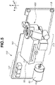
- Fig. 5 is a perspective view of the circuit substrate 100 viewed from a main body back side.
- the electronic components 111 having larger sizes in the Y direction than those of other members are gathered in a lower part of the wiring plate 101 for effectively utilizing a space, and are mounted in such a manner as to fit within a lower part of the scanner unit 50.
- a power input unit 115 is provided at an end portion of the wiring plate 101.
- the power input unit 115 is connected with an inlet 116 to be described below, and receives power supply from a commercial power source.
- Fig. 6 is a diagram of the circuit substrate 100 viewed from the main body left side. Because the installation portion 200 overlaps a part of the scanner unit 50, and the part is actually located at an invisible position, this region is indicated by a dashed-dotted line.
- the scanner unit 50 is arranged at a position most appropriate for irradiating the photosensitive drum 11 with laser light indicated by a dotted line.
- members such as the electronic components 111 that considerably protrude from the plate surface are not arranged. In other words, the scanner unit 50 and the electronic component 111 are arranged by being shifted in the Z direction in such a manner as not to interfere with each other.
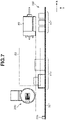
- Fig. 7 is an enlarged top view of the circuit substrate 100 viewed from the main body top surface.
- the scanner unit 50 and the electronic component 111 are arranged at positions partially overlapping with each other.
- the electronic component 111 is originally invisible from this direction.
- the scanner unit 50 is indicated by a dotted line, and the electronic component 111 is illustrated in a perspective manner.
- a distance in the Y direction (front-back direction) between the circuit substrate 100 and the scanner unit 50 can be shortened, and the image forming apparatus 1 can be downsized.
- the drive motor 60 has a function of rotating the photosensitive drum 11 and a conveyance member (the pickup roller 3, the feeding roller 5a, the conveyance roller pair 5c, etc.) for feeding and conveying the recording material P.
- the drive motor 60 protrudes toward the minus side in the X direction, and the wiring plate 101 is arranged on the main body front side of the drive motor 60.
- the electronic component 111 is mounted by avoiding the drive motor 60 in such a manner as not to interfere with the drive motor 60.
- the drive motor 60 and the electronic component 111 are arranged at positions partially overlapping each other.
- the drive motor 60 and the electronic component 111 are arranged by being shifted in the X direction in such a manner as not to interfere with each other.
- Fig. 8 is a diagram obtained by adding the right plate frame 72 and a scanner holding member 40 to the perspective view in Fig. 5 .
- the illustration of the left plate frame 73 and the base frame 74 is omitted.
- the scanner unit 50 is held by the scanner holding member 40.
- the scanner holding member 40 is fixed to the right plate frame 72 and the left plate frame 73 (not illustrated in Fig. 8 ), and is configured to pass through the lower part of the installation portion 200 and bridge the two frames.
- the drive motor 60 is attached to the right plate frame 72, and a gear coupled to the drive motor 60 is provided on the X direction plus side (right side) of the right plate frame 72. Drive force of the drive motor 60 is transmitted to the feeding roller 5a and the photosensitive drum 11 via the gear.
- Fig. 9 is a back view of the circuit substrate 100 viewed from the main body back side.
- Fig. 9 illustrates not only the circuit substrate 100 but also the scanner unit 50, the drive motor 60, and the installation portion 200 together.
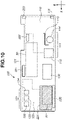
- Fig. 10 illustrates only the circuit substrate 100.
- the circuit substrate 100 includes a low-voltage power source unit 110 that takes in alternating-current power from an external commercial power source and converts the alternating-current power into direct-current power, and a high-voltage power source unit 120 for supplying a high voltage necessary for image formation, to each process member.
- the low-voltage power source unit 110 and the high-voltage power source unit 120 are mounted on the same substrate.
- the low-voltage power source unit 110 includes a low-voltage power transformer 112, a heatsink 113, and an electrolytic capacitor 114 as the electronic components 111 having large sizes in the Y direction.
- the low-voltage power source unit 110 further includes the power input unit 115.
- the high-voltage power source unit 120 includes a charging transformer 122, a development transformer 123, and a transfer transformer 124 as the electronic components 121 having large sizes in the Y direction. As clearly seen from Fig. 9 , all the electronic components 111 and 121 having large sizes in the Y direction are arranged in such a manner as to avoid the positions of the scanner unit 50, the drive motor 60, and the installation portion 200.
- a plurality of connectors 220, 221, 222, and 223 is provided at upper or lower end portions of the circuit substrate 100, and the circuit substrate 100 is connected with various members by a bundle wire.
- the connector 220 is connected with the drive motor 60 and a sensor (not illustrated) that detects the recording material P being conveyed.
- the connector 221 is connected with a laser output unit (not illustrated) of the scanner unit 50, and a scanner motor (not illustrated) for rotating a polygon mirror.
- the connector 222 is connected with a control panel (not illustrated) including a power switch and an execution key to be operated by the user, and a video controller 140.
- the connector 223 is connected with the fixing heater 9c.
- a resistor and a jumper line are provided in a shaded portion 224 facing the drive motor 60.
- the resistor provided at the position has a function of adjusting various biases output from the charging transformer 122, the development transformer 123, and the transfer transformer 124.
- Fig. 11 is a block diagram illustrating functions of the circuit substrate 100.
- the low-voltage power source unit 110 takes in power from an external power source via the power input unit 115 mounted at a substrate end portion, and converts an alternating-current voltage into a stable direct-current voltage by a rectification smoothing circuit including an electrolytic capacitor 114. After that, the low-voltage power source unit 110 converts a direct-current voltage into a high-frequency alternating-current voltage by a switching element such as a transistor, and inputs the high-frequency alternating-current voltage to the low-voltage power transformer 112. The low-voltage power transformer 112 converts the high-frequency alternating-current voltage, which is an input voltage, into an alternating-current voltage (output voltage) having a desired voltage value.
- the low-voltage power source unit 110 converts the alternating-current voltage into a direct-current voltage again, and outputs the obtained direct-current voltage to the high-voltage power source unit 120. Because the loss of individual circuit components appears as heat in the low-voltage power source unit 110, the heatsink 113 manufactured using aluminum or iron is provided for releasing heat.
- the high-voltage power source unit 120 converts a voltage (e.g., 24 V) supplied from the low-voltage power source unit 110, into a high voltage necessary for an image forming process such as charging, development, and transfer.
- the charging transformer 122 converts a voltage supplied from the low-voltage power source unit 110, into a charging voltage, and the converted voltage is then supplied to the charging roller 17.
- the development transformer 123 converts a voltage supplied from the low-voltage power source unit 110, into a development voltage, and the converted voltage is then supplied to the development roller 12.
- the transfer transformer 124 converts a voltage supplied from the low-voltage power source unit 110, into a transfer voltage, and the converted voltage is then supplied to the transfer roller 7.
- the low-voltage power source unit 110 supplies a voltage (e.g., 3.3 V or 5 V) not only to the high-voltage power source unit 120 but also to the scanner unit 50, the drive motor 60, an engine controller 130, and the video controller 140.
- the engine controller 130 functions as a control unit that comprehensively controls various process members.
- the engine controller 130 includes a central processing unit (CPU) (not illustrated), a random access memory (RAM) (not illustrated) used for calculating and temporarily storing data necessary for controlling the image forming apparatus 1, and a read-only memory (ROM) (not illustrated) storing programs and various types of data for controlling the image forming apparatus 1.
- the video controller 140 has a function of receiving print data by communicating with an external device such as a personal computer, and notifying the engine controller 130 of an analysis result of the print data.
- the engine controller 130 and the video controller 140 may be provided on a substrate different from the circuit substrate 100, or may be provided on the same substrate. In the present exemplary embodiment, the engine controller 130 is provided on the circuit substrate 100 as illustrated in Figs. 9 and 10 .
- Alternating-current power received by the power input unit 115 from a commercial power source is supplied not only to the low-voltage power source unit 110 but also to the fixing heater 9c.
- a triac (not illustrated) is provided between the power input unit 115 and the connector 223.
- the temperature of the fixing heater 9c can be adjusted by switching between on and off of the triac and changing a sinusoidal waveform.
- the rollers in the fixing device 9 are driven by the drive motor 60.
- the installation portion 200 will be described with reference to Figs. 12 to 16 .
- the image forming apparatus 1 is provided with the installation portion 200 for supplying toner from the outside without detaching the container 18 from the housing 720 in a case where a remaining amount of toner in the container 18 becomes small.
- the installation portion 200 has a configuration to which the replenishment pack 310 serving as a replenishment cartridge, which will be described below, can be attached.
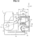
- Fig. 12 is a left side view of the image forming apparatus 1 viewed from the rotational axis direction of the photosensitive drum 11.
- the installation portion 200 includes an operation unit 201 to which the replenishment pack 310 (not illustrated in Fig. 12 ) is to be attached, a toner acceptance portion 202 having a cylindrical shape, and a replenishment pathway portion 203 connecting the container 18 and the toner acceptance portion 202.
- the operation unit 201 forms a replenishment port 204, which is a space for inserting the replenishment pack 310.
- the operation unit 201 includes a rotary lever 201b serving as a grip member to be gripped by the user for rotating the operation unit 201.
- the installation portion 200 overlaps a part of the scanner unit 50 and the part is actually located at an invisible position, this region is indicated by a dotted line in Fig. 12 .
- the toner acceptance portion 202 and the replenishment pathway portion 203 of the installation portion 200 overlap the scanner unit 50. More specifically, the toner acceptance portion 202 and the replenishment pathway portion 203 are located at positions overlapping the scanner unit 50 in the Z direction.
- R1 and R2 overlap.
- a virtual surface passing through an upper end portion 18b located at an uppermost position of a frame member 18a of the container 18, and being parallel to the horizontal surface is denoted by S.
- the virtual surface S is indicated by a dashed-dotted line.
- a part of the installation portion 200 is located on the plus side (upside) in the Z direction with respect to the virtual surface S.
- a part of the installation portion 200 protrudes toward the upside with respect to the upper end portion 18b of the container 18.
- the part of the installation portion 200 includes the entire operation unit 201, a part of the toner acceptance portion 202, and a part of the replenishment pathway portion 203.
- the parts of the toner acceptance portion 202 and the replenishment pathway portion 203 that protrude toward the upside from the virtual surface S overlap the scanner unit 50.
- a drum frame member 11a supporting the photosensitive drum 11 overlaps a part of the container 18, and the part is actually located at an invisible position, the region is indicated by a dotted line.
- the container 18 supports the development roller 12 bearing developer. Because the development roller 12 is actually located at an invisible position as well, the development roller 12 is indicated by a dotted line in Fig. 12 .
- a communication unit 209 is provided at a place facing an insertion direction of a replenishment container.
- the details of the function of the communication unit 209 will be described below.
- Fig. 13 is a top view of the image forming apparatus 1 from which the exterior cover 71 is removed.
- the operation unit 201 forms the replenishment port 204 through which an insertion portion 312 passes.
- the operation unit 201 includes a ring portion 201a arranged in such a manner as to surround the replenishment port 204, and the rotary lever 201b connected to the ring portion 201a.
- a width in the X direction of the installation portion 200 is shorter than a width in the X direction of the container 18.
- a width of the scanner unit 50 in the X direction is shorter than a width of the photosensitive drum 11 in the X direction.
- a space is consequently produced between the left end of the scanner unit 50 and the left plate frame 73, and the installation portion 200 is provided in the space in the present exemplary embodiment.
- the installation portion 200 is provided between the scanner unit 50 and the left plate frame 73 in the X direction.
- the replenishment port 204 and the scanner unit 50 are adjacently provided within a region in the X direction in which the container 18 is provided.
- the installation portion 200 is provided on the opposite side of the drive motor 60 across the scanner unit 50. Because the drive motor 60 employed in the present exemplary embodiment is relatively small, as illustrated in Fig. 13 , the installation portion 200 and the drive motor 60 do not overlap in the Z direction. Thus, the installation portion 200 and the drive motor 60 can be provided on the same side of the scanner unit 50. Nevertheless, in a case where the drive motor 60 having a larger size is employed, the installation portion 200 is to be provided at a position shifted upward. The image forming apparatus 1 consequently upsizes.
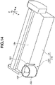
- Fig. 14 is a perspective view of a developer container 230 including the container 18 and the installation portion 200.
- the illustration of the operation unit 201 of the installation portion 200, and some members associated with the operation unit 201 is omitted.
- the installation portion 200 includes an acceptance opening 205 that leads to the replenishment pathway portion 203 and that is formed on an inside wall of the toner acceptance portion 202 having a cylindrical shape.
- the acceptance opening 205 is a lateral opening provided on the side surface of the inside wall of the toner acceptance portion 202. Toner is guided from the toner acceptance portion 202 to the replenishment pathway portion 203 via the acceptance opening 205, and then stored into the container 18 via the replenishment pathway portion 203.
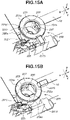
- Figs. 15A and 15B are enlarged perspective views of the installation portion 200.
- the main body shutter portion 206 is a cylindrical member concentric with the toner acceptance portion 202, and is provided inside the toner acceptance portion 202.
- a shutter opening 207 for letting toner through is also formed on the main body shutter portion 206.
- the shutter opening 207 is a connecting opening for connecting the acceptance opening 205 and a lateral opening 313 (refer to Fig. 17 ).
- the acceptance opening 205 and the shutter opening 207 are located at shifted positions in Fig. 15A , the acceptance opening 205 is blocked.
- a first drive force transmission rib 201d of the operation unit 201 and a second drive force transmission rib 206a of the main body shutter portion 206 can engage with a drive force transmitted unit 314b of a pack shutter portion 314, which will be described below in detail.
- the drive force transmitted unit 314b of the pack shutter portion 314 is an engaged portion.
- the second drive force transmission rib 206a of the main body shutter portion 206 is a first engagement portion included in a movable member (second rotary member).
- the first drive force transmission rib 201d of the operation unit 201 is a second engagement portion.
- the user can grip the rotary lever 201b, and rotate the rotary lever 201b by approximately 90° from the state in Fig. 15A to the state in Fig. 15B .
- the main body shutter portion 206 which is a movable member, can be rotated within the toner acceptance portion 202 of the main body shutter portion 206 in accordance with the rotation of the rotary lever 201b.
- the main body shutter portion 206 is a movable member included in a regulation unit, or the main body shutter portion 206 is also a second rotary member.
- the acceptance opening 205 and the shutter opening 207 are located at overlapping positions, the acceptance opening 205 is open, and toner can be supplied via the acceptance opening 205 in this state.
- toner is agitated within the container 18 by an agitation member (not illustrated).
- the acceptance opening 205 is blocked in such a manner as to prevent toner from leaking from the acceptance opening 205.
- the rotary lever 201b is moved to a first position illustrated in Fig. 15A .
- the first position will be referred to as a default position.
- the main body shutter portion 206 and the rotary lever 201b rotate integrally, the main body shutter portion 206 is also located at the default position in a state in which the rotary lever 201b is located at the default position.
- the acceptance opening 205 is to be opened.
- the rotary lever 201b is therefore caused to reach a second position illustrated in Fig. 15B , at the time of toner replenishment.
- the second position is a regulation position at which the replenishment pack 310 is regulated in such a manner as not to be detached, and is also a replenishment position at which toner is supplied from the replenishment pack 310.
- the second position is a position distant from the first position.
- the main body shutter portion 206 and the rotary lever 201b rotate integrally, the main body shutter portion 206 is also located at the regulation position in a state where the rotary lever 201b is located at the regulation position.
- the operation unit 201 is provided with a detected rib portion 201c serving as a detected portion, and a lever detection sensor 225, which is a first detection device for detecting the rotation of the rotary lever 201b gripped and rotated to the replenishment position.
- the lever detection sensor 225 is a contact-type sensor that conveys an ON signal to the engine controller 130 as a detection signal by detecting the contact of the detected rib portion 201c.
- a contactless sensor may be employed as the lever detection sensor 225.
- a toner suppliable state is caused as illustrated in Fig. 15B .
- the agitation of toner in the container 18 is started by the agitation member (not illustrated). This prevents the stagnation of toner near the acceptance opening 205, and enables a smooth toner replenishment operation.
- the toner acceptance portion 202 further includes a regulation rib 202a.
- a regulation unit that regulates the detachment of the replenishment pack 310 from the installation portion 200 in the Z direction is included.
- the regulation unit includes the regulation rib 202a of the toner acceptance portion 202 and the main body shutter portion 206 that moves the pack shutter portion 314.
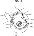
- Fig. 16 is an enlarged perspective view of the communication unit 209.
- the communication unit 209 includes a main body electric contact portion 209a serving as a first electric contact portion, and the main body electric contact portion faces toward the Z direction plus side (upside).
- the communication unit 209 is pressed toward the Z direction plus side by a pressing member 219 (not illustrated in Fig. 16 ).
- the main body shutter portion 206 further includes the second drive force transmission rib 206a, and a core positioning hole 206b for positioning a core of the replenishment pack 310.
- Fig. 17B is a diagram of the replenishment pack 310 viewed from an angle different from that in Fig. 17A .
- the replenishment pack 310 includes a pouch portion 311 storing toner to be supplied, and the cylindrical insertion portion 312 to be inserted into the replenishment port 204.
- the pouch portion 311 is a storing unit that stores toner.
- the replenishment pack 310 is attached to the installation portion 200 with the insertion portion 312 being regarded as a leading end side.
- the replenishment pack 310 further includes the lateral opening 313, which is a discharge opening for discharging toner and formed on the side surface of the insertion portion 312, and the pack shutter portion 314 for stopping up the lateral opening 313 in such a manner that toner does not leak from the lateral opening 313.
- the pack shutter portion 314 is a first rotary member rotatable for opening and closing the lateral opening 313.
- the pouch portion 311 has a shape flattened toward the opposite side of the insertion portion 312, and a pouch end portion 316 extending in a predetermined direction is formed at the end of the pouch portion 311.
- a memory tag 318 serving as a memory device is provided on the bottom surface of the insertion portion 312.
- the bottom surface means a bottom surface in the Z direction in a state where the replenishment pack 310 is attached to the replenishment port 204.
- the pack shutter portion 314 is a cylindrical member concentric with the insertion portion 312, and is provided on the outside of the insertion portion 312.
- the pack shutter portion 314 is configured to be rotatable with respect to the insertion portion 312. If the pack shutter portion 314 rotates and an opening of the pack shutter portion 314 and the lateral opening 313 of the insertion portion 312 match, toner can be supplied from the replenishment pack 310.
- the drive force transmitted unit 314b is provided on the side surface of the pack shutter portion 314. When the replenishment pack 310 is inserted into the replenishment port 204, the drive force transmitted unit 314b engages with the first drive force transmission rib 201d and the second drive force transmission rib 206a illustrated in Figs. 15A and 15B .
- a positioning slit portion 314c is provided on the side surface of the pack shutter portion 314.
- the regulation rib 202a provided on the above-described toner acceptance portion 202 enters the positioning slit portion 314c.
- the regulation rib 202a is in a state of being contactable with the positioning slit portion 314c.
- Fig. 18A is an enlarged perspective view of the memory tag 318 arranged on the bottom surface of the replenishment pack 310.
- Fig. 18B is an enlarged view illustrating only the memory tag 318.
- the memory tag 318 is a plate-like member with an area of 5.5 mm ⁇ 5 mm, and a thickness of 1.4 mm.
- the memory tag 318 is fixed to the insertion portion 312 in a state where an electric contact portion 318a serving as a second electric contact portion is exposed toward the bottom surface side.
- the memory tag 318 includes a storage element 318d on a rear surface 318c on the opposite side of a front surface 318b on which the electric contact portion 318a is provided.
- the storage element 318d stores information regarding the replenishment pack 310 such as a lot number, an amount of stored toner, and characteristics information of the replenishment pack 310, and characteristics information of an image forming apparatus to which the replenishment pack 310 is to be attached.
- the engine controller 130 of the image forming apparatus 1 reads out information in the storage element 318d, and uses the information for controlling the image forming apparatus 1.
- a core positioning rib 312a for positioning a core of the main body shutter portion 206 when the replenishment pack 310 is attached to the installation portion 200 is provided on the bottom surface of the replenishment pack 310.
- a configuration in which the storage element 318d communicating with the electric contact portion 318a is held on a portion other than the bottom surface of the insertion portion 312, and is connected therefrom with the electric contact portion 318a on the bottom surface by a conductive member such as a coil spring may be adopted.
- FIGs. 19A and 19B are perspective views of the image forming apparatus 1 in a state where the discharge tray 14 is opened or closed.
- the discharge tray 14 has a retractable configuration movable between a stack position illustrated in Fig. 19A , at which the discharge tray 14 covers the installation portion 200 and the recording material P discharged from the discharge port 15 can be stacked, and a position illustrated in Fig. 19B , at which the installation portion 200 is exposed. Because the installation portion 200 is provided in an upper part of the main body front surface of the image forming apparatus 1, the user can easily access the installation portion 200 at the time of replenishment.
- the recording material P stacked on the discharge tray 14 is removed, and the discharge tray 14 is opened and moved to the position illustrated in Fig. 19B . If the discharge tray 14 is opened, the installation portion 200 and a top surface portion 240 provided adjacently to the installation portion 200 are exposed. Then, the replenishment pack 310 is inserted into the exposed installation portion 200. At this time, as described above, the replenishment pack 310 is inserted in such a manner that the positions of the first drive force transmission rib 201d and the second drive force transmission rib 206a ( Fig. 15 ) provided on the installation portion 200, and the drive force transmitted unit 314b ( Fig. 18 ) provided on the replenishment pack 310 match.
- Fig. 20A illustrates a state in which the replenishment pack 310 is inserted into the installation portion 200.
- the replenishment pack 310 can be inserted.
- Fig. 20B illustrates a state in which the rotary lever 201b is moved from the default position to the replenishment position.
- the entire pouch portion 311 of the replenishment pack 310 is not accommodated inside the image forming apparatus 1, and the pouch portion 311 is exposed to the outside of the image forming apparatus 1.
- a configuration in which the insertion portion 312 and a part of the pouch portion 311 are accommodated inside the image forming apparatus 1 may be adopted.
- Fig. 21 is a cross-sectional enlarged view illustrating the memory tag 318 in a state where the replenishment pack 310 is attached. While the replenishment pack 310 is being inserted, the side surface of the core positioning rib 312a ( Fig. 18 ) arranged on the bottom surface of the insertion portion 312 of the replenishment pack 310 engages with the core positioning hole 206b of the main body shutter portion 206, and the core is positioned. Then, the core positioning rib 312a of the replenishment pack 310 engages with the communication unit 209, and the electric contact portion 318a of the memory tag 318 and the main body electric contact portion 209a of the communication unit 209 contact and enter a state in which communication can be electrically performed.
- the communication unit 209 is pressed by the pressing member 219 toward the direction of the memory tag 318, and a position in the Z direction is determined by an abutting portion 209b of the communication unit 209 abutting an abutting portion 312b of the insertion portion 312. In this way, contact pressure of the electric contact portion is ensured.
- Figs. 22A and 22B are perspective views illustrating a regulation unit for regulating the detachment of the replenishment pack 310 from the installation portion 200 in a detachment direction. For making the components easily viewable, a part of components such as the operation unit 201 is not displayed.
- the positioning slit portion 314c of the replenishment pack 310 and the regulation rib 202a of the toner acceptance portion 202 are not engaged, and the replenishment pack 310 is in a state of being detachable from the installation portion 200.
- a state in which the regulation rib 202a provided on the toner acceptance portion 202 enters the positioning slit portion 314c is caused.
- This state is a state in which the positioning slit portion 314c engages with the regulation rib 202a, and the replenishment pack 310 is positioned in the Z direction. In other words, this state is a state in which the replenishment pack 310 cannot be detached from the installation portion 200.
- the replenishment pack 310 In a state where the rotary lever 201b is located at the default position, the replenishment pack 310 might be detached from the installation portion 200 while power supply or communication is being performed between the engine controller 130 and the memory tag 318. In a state of being attached to the installation portion 200, the replenishment pack 310 is not accommodated inside the image forming apparatus 1 and the pouch portion 311 of the replenishment pack 310 is visible to the user. Thus, while power supply or communication is being performed between the engine controller 130 and the memory tag 318, the replenishment pack 310 might be detached from the installation portion 200.
- the authentication might fail due to the detachment of the replenishment pack 310 from the installation portion 200.
- the replenishment pack 310 By detaching the replenishment pack 310 from the installation portion 200 while communication is being performed between the engine controller 130 and the memory tag 318, the memory tag 318 might be damaged.
- the present exemplary embodiment is characterized in that power supply between the memory tag 318 and the engine controller 130 is started after the regulation unit causes a state in which the replenishment pack 310 cannot be detached from the installation portion 200.
- the main body shutter portion 206 and the pack shutter portion 314 rotate, and the acceptance opening 205 ( Fig. 15 ) formed on the toner acceptance portion 202 opens.
- the lateral opening 313 ( Fig. 17 ) formed on the insertion portion 312 is configured to open together with the opening of the acceptance opening 205.
- the acceptance opening 205 formed on the toner acceptance portion 202 and the lateral opening 313 formed on the insertion portion 312 are in a positional relationship of facing each other when the replenishment pack 310 is inserted into the installation portion 200.
- the lever detection sensor 225 detects the rotation. Being triggered by the detection, communication of the memory tag 318 is started by the control of the engine controller 130.
- the above-described regulation unit keeps a region in which the replenishment pack 310 is operable with respect to the installation portion 200 within a range in which the communication unit 209 pressed by pressing member 219 can maintain a contact state with the memory tag 318 and can track the memory tag 318.
- a contact state between the memory tag 318 and the communication unit 209 is guaranteed, and stable communication can be performed.
- Fig. 23 is a flowchart illustrating a timing of communication between the engine controller 130 and the memory tag 318 according to the present exemplary embodiment.
- step S101 the replenishment pack 310 is attached to the exposed installation portion 200.
- step S102 the engine controller 130 determines whether the lever detection sensor 225 has detected the detected rib portion 201c of the operation unit 201. In a case where the lever detection sensor 225 has detected the detected rib portion 201c (YES in step S102), the processing proceeds to step S103. In step S103, power supply to the memory tag 318 is started. As described above, a state in which the lever detection sensor 225 has detected the detected rib portion 201c of the operation unit 201 is a state in which the replenishment pack 310 is regulated in such a manner as not to be detached from the installation portion 200.
- the replenishment pack 310 is in a state of being regulated in such a manner as not to be detached from the installation portion 200, even when power supply from the engine controller 130 to the memory tag 318 is started, a failure in communication or authentication, and damages to the memory tag 318 can be prevented.
- power supply from the engine controller 130 and communication between the memory tag 318 and the engine controller 130 are concurrently performed via the main body electric contact portion 209a and the electric contact portion 318a.
- an authentication sequence is executed. In the authentication sequence, for example, a lot number of the replenishment pack 310, an amount of stored toner, and characteristic information are read out from the memory tag 318.
- step S104 the authentication sequence is completed during the replenishment operation, and communication between the engine controller 130 and the memory tag 318 ends.
- step S105 it is determined whether the lever detection sensor 225 is in an off state. If the lever detection sensor 225 is in an off state (YES in step S105), power supply from the engine controller 130 to the memory tag 318 has already ended. Thus, the processing proceeds to step S106. In step S106, the replenishment pack 310 is detached from the installation portion 200 while preventing damages to the memory tag 318.
- a contact state between the memory tag 318 and the communication unit 209 is guaranteed by the regulation unit, and stable communication can be performed between the memory tag 318 and the engine controller 130.
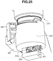
- Fig. 24 is a perspective view illustrating a modified example.
- the second lever detection sensor 226 serving as a second detection device is arranged at a position at which the second lever detection sensor 226 detects the rotation when the rotary lever 201b is rotated from the default position by approximately 10°.
- the second lever detection sensor 226 is a contact-type sensor similar to the lever detection sensor 225.
- Positioning in the Z direction of the replenishment pack 310 is completed when the rotary lever 201b is rotated from the default position by approximately 10°. At that timing, the rotation of the rotary lever 201b is locked by a certain mechanism (not illustrated) such as a solenoid. If the second lever detection sensor 226 enters an on state in a state where detachment of the replenishment pack 310 is regulated, the engine controller 130 supplies power to the memory tag 318, and starts communication. Then, after the completion of communication, the lock in the rotational direction of the rotary lever 201b is canceled and rotated up to 90°. At the position, the rotary lever 201b is detected by the lever detection sensor 225, and a toner suppliable state is caused. According to the configuration of the modified example, toner replenishment is not performed until communication is completed, and after the completion of communication, toner replenishment can be started.
- a regulation rib provided in the replenishment pack 310 may overlap a slit portion provided in the toner acceptance portion 202.
- the regulation in the Z direction of the replenishment pack 310 with respect to the installation portion 200 is performed by an operation of integrally rotating the rotary lever 201b and the main body shutter portion 206, which is a movable member, but the operation needs not be a rotating operation.
- the regulation in the Z direction of the replenishment pack 310 with respect to the installation portion 200 may be performed.
- the regulation in the Z direction of the replenishment pack 310 with respect to the installation portion 200 is performed in conjunction with a rotational movement of the main body shutter portion 206 and the pack shutter portion 314 used for opening and closing the lateral opening 313, but the regulation needs not be performed in conjunction with the rotational movement.
- the main body shutter portion 206 and the pack shutter portion 314 may be configured to rotate after the regulation is completed by the regulation unit.
- the description has been given of a configuration of preventing detachment of the replenishment pack 310 and opening and closing the shutter of the replenishment pack 310 by rotating the rotary lever 201b provided in the operation unit 201.
- the description will be given of a configuration of preventing detachment of the replenishment pack 310 and opening and closing the shutter of the replenishment pack 310 in a configuration not having the operation unit 201.
- an installation detection sensor 407 serving as an installation detection means for detecting the installation of the replenishment pack 310 is arranged on the bottom surface of a replenishment unit.
- the installation detection sensor 407 is a contact-type sensor, but may be a contactless sensor.
- a main body shutter portion 506 includes a worm wheel portion 506a, and drive force can be transmitted from a brush motor 401 via a gear train portion 404, including a plurality of gears, and a worm gear 403.
- the main body shutter portion 506 serves as a movable member provided in the regulation unit, or the main body shutter portion 506 also serves as a second rotary member.
- the regulation unit includes the regulation rib 202a of the toner acceptance portion 202 and the main body shutter portion 506 that moves the pack shutter portion 314.
- An encoder 402 and a rotation detection sensor 408 arranged inside a drive train are provided for performing rotation control of the brush motor 401.
- a second detection device that detects the number of rotations of the brush motor 401 includes the encoder 402 and the rotation detection sensor 408.
- a position detection sensor 409 (first detection device in the second exemplary embodiment) for detecting a rotational position of the main body shutter portion 506 is included.
- the main body shutter portion 506 includes a position detection rib 506b.
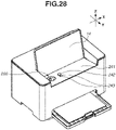
- drive force transmission components such as a top surface portion 241 and the worm gear 403 are arranged so as to extend along the angle of the discharge tray 14.
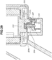
- the worm gear 403 By obliquely arranging the worm gear 403 so as to extend along the top surface portion 241, it becomes possible to fit almost all the drive force transmission components within a width in the height direction of the installation portion 200, and this contributes to the downsizing of the image forming apparatus.
- a detachment button 242 to be used by the user for detaching the replenishment pack 310 from the installation portion 200 after the completion of toner replenishment performed by the user is provided on the right side of the installation portion 200 of the top surface portion 241.
- Light-emitting diode (LED) lamps 242 and 243 for notifying the user of a state during a replenishment operation are also provided on the right side of the installation portion 200 of the top surface portion 241.
- the detachment button 242 and the LED lamps 243 are connected to the engine controller 130.
- a toner replenishment operation according to the present exemplary embodiment, and operations of power supply and communication between the engine controller 130 and the memory tag 318 will be described with reference to a cross-sectional view in Fig. 29 and perspective views in Figs. 30A to 30C .
- Fig. 30A illustrates a position in a state where the replenishment pack 310 is attached to the installation portion 200
- Fig. 30B illustrates a position in a state where the replenishment pack 310 is regulated in such a manner as not to be detached from the installation portion 200.
- the engine controller 130 supplies power to the memory tag 318 and communicates with the memory tag 318.
- Fig. 30C illustrates a position at which toner replenishment can be performed from the replenishment pack 310.
- the installation detection sensor 407 In a state before the replenishment pack 310 is inserted, the installation detection sensor 407 is in an OFF state and the position detection sensor 409 is in an ON state.
- the brush motor 401 starts to be driven to rotate in a positive direction.
- a drive force transmission rib (first engagement portion) of the main body shutter portion 506 and a drive force transmitted rib (second engagement portion) of the pack shutter portion 314 engage with each other when the replenishment pack 310 is attached, and drive force transmission can be performed.
- the main body shutter portion 506 rotates integrally with the pack shutter portion 314.
- the main body shutter portion 506 when the position detection sensor 409 is in an ON state, the main body shutter portion 506 is located at the first position (default position).
- the engine controller 130 reads a signal of the rotation detection sensor 408, and stops the brush motor 401 at the position at which the main body shutter portion 506 is rotated by approximately 10° ( Fig. 30B ).
- the regulation rib 202a in the Z direction provided on the toner acceptance portion 202 enters the positioning slit portion 314c provided on the pack shutter portion 314.
- the position at which the main body shutter portion 506 is rotated by approximately 5° is a regulation position, and serves as the second position.
- the engine controller 130 starts power supply to the memory tag 318 in this state and communicates with the memory tag 318.
- a region in which the replenishment pack 310 is operable with respect to the installation portion 200 falls within a range in which the communication unit 209 pressed by pressing member 219 can maintain a contact state with the memory tag 318 and can track the memory tag 318.
- a contact state between the memory tag 318 and the communication unit 209 is guaranteed, and stable communication can be performed.
- the lateral opening 313 for toner replenishment is not open, toner replenishment is not performed.
- the engine controller 130 again drives the brush motor 401 to rotate in the position direction, and stops the brush motor 401 at the replenishment position at which the main body shutter portion 506 is rotated from the default position by approximately 90° ( Fig. 30C ).
- a position at which the main body shutter portion 506 is rotated by about 90° is the replenishment position, and also serves as a third position.
- the replenishment pack 310, the installation portion 200, and the container 18 connect with each other, and toner replenishment can be performed. Then, when replenishment is completed by a replenishment operation performed by the user, by the user operating the detachment button 242, the brush motor 401 is rotated inversely, and rotates the main body shutter portion 506 up to the default position. It thereby becomes possible for the user to detach the replenishment pack 310.
- a toner replenishment procedure and a communication procedure of the memory tag 318 according to the present exemplary embodiment have been described above.
- a failure in communication between the engine controller 130 and the memory tag 318 includes communication being unestablished due to a contact failure between the electric contact portion 318a of the memory tag 318 and the main body electric contact portion 209a of the communication unit 209.
- a failure in communication between the engine controller 130 and the memory tag 318 also includes a failure in authentication in the authentication sequence between the engine controller 130 and the memory tag 318.
- the authentication sequence is a sequence for determining whether a presupposed replenishment pack 310 is attached to the image forming apparatus 1 by exchanging information between the engine controller 130 and the memory tag 318. For example, if the user erroneously attaches a replenishment pack storing yellow toner to the image forming apparatus 1 supposed to use black toner as toner to be supplied, and the container 18 of the image forming apparatus 1 is replenished with yellow toner, black toner and yellow toner are mixed within the container 18, which may cause a disadvantage to the user.
- the engine controller 130 of the image forming apparatus 1 may determine the authentication to be a failure, and rotate the brush motor 401 inversely.
- Fig. 31 is a flowchart illustrating a timing of communication between the engine controller 130 and the memory tag 318 according to the present exemplary embodiment.
- step S201 the replenishment pack 310 is attached to the exposed installation portion 200.
- step S202 the engine controller 130 determines whether the installation detection sensor 407 is switched to ON by the installation detection rib 312c of the replenishment pack 310. In a case where it is determined that the installation detection sensor 407 is switched to ON (YES in step S202), the processing proceeds to step S203.
- step S203 the brush motor 401 is rotated in a positive direction. While the brush motor 401 is rotating in the positive direction, the LED lamp 243 may be lit up in red.
- step S204 the position detection sensor 409 switches from ON to OFF by the rotation of the main body shutter portion 506.
- step S205 the engine controller 130 reads a signal of the rotation detection sensor 408, and stops the brush motor 401 at the position at which the main body shutter portion 506 is rotated by approximately 10°.
- a state in which the brush motor 401 is stopped is a state in which the replenishment pack 310 is regulated in such a manner as not to be detached from the installation portion 200. Because the replenishment pack 310 is in a state of being regulated in such a manner as not to be detached from the installation portion 200, communication from the engine controller 130 to the memory tag 318 is started.
- the LED lamp 243 may be lit up in red.
- the lateral opening 313 of the replenishment pack 310 is closed by the pack shutter portion 314. Thus, toner replenishment is not performed.
- step S206 it is determined whether communication from the engine controller 130 to the memory tag 318 has succeeded. In a case where the communication has succeeded (YES in step S206), the processing proceeds to step S207. In step S207, communication from the engine controller 130 to the memory tag 318 is ended.
- the engine controller 130 drives the brush motor 401 to rotate in the positive direction again, and stops the brush motor 401 at the replenishment position at which the main body shutter portion 506 is rotated from the default position by approximately 90°.
- step S208 it is determined whether the user has operated the detachment button 242. In a case where the detachment button 242 is turned on (YES in step S208), the processing proceeds to step S209.
- step S209 the engine controller 130 rotates the brush motor 401 in a negative direction, and rotates the main body shutter portion 506 up to the default position. While the brush motor 401 is rotating in the negative direction, the LED lamp 243 may be lit up in red. Alternatively, if the position detection sensor 409 switches from OFF to ON by the negative rotation of the main body shutter portion 506, the LED lamp 242 may be lit up in green.
- the LED lamps 242 and 243 may be lit up or blinked in accordance with the phase of the main body shutter portion 506 as in the present exemplary embodiment. Alternatively, for example, the LED lamps 242 and 243 may be lit up or blinked in accordance with a timing of communication from the engine controller 130 to the memory tag 318. Then, in step S210, the replenishment pack 310 is detached from the installation portion 200.
- a contact state between the memory tag 318 and the communication unit 209 is guaranteed by the regulation unit, and stable communication can be performed between the memory tag 318 and the engine controller 130.
- An image forming system is characterized in that a control unit communicates with a memory device via a first electric contact portion and a second electric contact portion after a replenishment cartridge is regulated in an installation portion by a regulation unit.
Landscapes
- Physics & Mathematics (AREA)
- General Physics & Mathematics (AREA)
- Electrophotography Configuration And Component (AREA)
- Dry Development In Electrophotography (AREA)
Applications Claiming Priority (1)
| Application Number | Priority Date | Filing Date | Title |
|---|---|---|---|
| JP2020187415A JP7562379B2 (ja) | 2020-11-10 | 2020-11-10 | 画像形成装置及び画像形成システム |
Publications (2)
| Publication Number | Publication Date |
|---|---|
| EP3995902A1 true EP3995902A1 (de) | 2022-05-11 |
| EP3995902B1 EP3995902B1 (de) | 2025-05-21 |
Family
ID=78500447
Family Applications (1)
| Application Number | Title | Priority Date | Filing Date |
|---|---|---|---|
| EP21205879.6A Active EP3995902B1 (de) | 2020-11-10 | 2021-11-02 | Bilderzeugungssystem |
Country Status (4)
| Country | Link |
|---|---|
| US (2) | US11841643B2 (de) |
| EP (1) | EP3995902B1 (de) |
| JP (1) | JP7562379B2 (de) |
| CN (1) | CN114460823B (de) |
Families Citing this family (1)
| Publication number | Priority date | Publication date | Assignee | Title |
|---|---|---|---|---|
| JP7770898B2 (ja) * | 2021-12-16 | 2025-11-17 | キヤノン株式会社 | 画像形成装置 |
Citations (4)
| Publication number | Priority date | Publication date | Assignee | Title |
|---|---|---|---|---|
| US20100119264A1 (en) * | 2008-11-10 | 2010-05-13 | Daichi Yamaguchi | Powder container, powder supplying device, and image forming apparatus |
| WO2020046338A1 (en) | 2018-08-30 | 2020-03-05 | Hewlett-Packard Development Company, L.P. | Contact pads for a print particle replenishment device |
| WO2020046421A1 (en) * | 2018-08-30 | 2020-03-05 | Hewlett-Packard Development Company, L.P. | Structure for selectively locking toner inlet shutter of toner refill portion |
| WO2020045763A1 (en) * | 2018-08-30 | 2020-03-05 | Hewlett-Packard Development Company, L.P. | Toner refill cartridge with holder holding memory unit thereon and rotatable with respect to cartridge body |
Family Cites Families (27)
| Publication number | Priority date | Publication date | Assignee | Title |
|---|---|---|---|---|
| JPS63101953U (de) * | 1986-12-24 | 1988-07-02 | ||
| US5392102A (en) * | 1992-05-26 | 1995-02-21 | Konica Corporation | Developing device having toner cartridge discriminator |
| DE4312667C2 (de) * | 1993-04-19 | 1995-06-08 | Weidmueller Interface | Prüfstecker für Reihenklemmen |
| US5619239A (en) * | 1993-11-29 | 1997-04-08 | Canon Kabushiki Kaisha | Replaceable ink tank |
| JPH09185238A (ja) * | 1995-12-28 | 1997-07-15 | Ricoh Co Ltd | 画像形成装置 |
| JP3476704B2 (ja) * | 1999-03-30 | 2003-12-10 | シャープ株式会社 | 画像形成装置 |
| JP4306953B2 (ja) | 2000-12-04 | 2009-08-05 | 株式会社リコー | 画像形成装置 |
| JP3625431B2 (ja) * | 2001-03-16 | 2005-03-02 | キヤノン株式会社 | プロセスカートリッジ着脱機構、プロセスカートリッジ及び電子写真画像形成装置 |
| JP4277480B2 (ja) * | 2001-05-11 | 2009-06-10 | セイコーエプソン株式会社 | 画像形成装置 |
| JP4378221B2 (ja) | 2003-10-08 | 2009-12-02 | キヤノン株式会社 | プロセスカートリッジ及び電子写真画像形成装置 |
| JP4380361B2 (ja) * | 2004-02-25 | 2009-12-09 | 富士ゼロックス株式会社 | トナー補給装置及びこれを用いた現像装置、画像形成装置 |
| JP4794892B2 (ja) * | 2005-04-11 | 2011-10-19 | キヤノン株式会社 | プロセスカートリッジ及び電子写真画像形成装置 |
| JP4894281B2 (ja) * | 2006-02-09 | 2012-03-14 | 富士ゼロックス株式会社 | 画像形成装置 |
| JP4330608B2 (ja) | 2006-11-09 | 2009-09-16 | シャープ株式会社 | 現像装置および画像形成装置 |
| JP5004833B2 (ja) * | 2007-05-23 | 2012-08-22 | キヤノン株式会社 | 電子写真画像形成装置 |
| JP5483196B2 (ja) | 2010-07-05 | 2014-05-07 | 株式会社リコー | 粉体収容器駆動装置、粉体搬送装置及び画像形成装置 |
| WO2013057006A1 (en) * | 2011-10-19 | 2013-04-25 | Oce-Technologies B.V. | Toner refill device |
| JP6028518B2 (ja) * | 2012-10-19 | 2016-11-16 | 富士ゼロックス株式会社 | 収容装置及び画像形成装置 |
| KR20150106729A (ko) * | 2014-03-12 | 2015-09-22 | 삼성전자주식회사 | 카트리지 및 이를 채용한 전자사진방식 화상형성장치 |
| KR101580224B1 (ko) | 2014-03-12 | 2015-12-24 | 삼성전자주식회사 | 카트리지 및 이를 채용한 전자사진방식 화상형성장치 |
| KR20160143391A (ko) * | 2015-06-05 | 2016-12-14 | 에스프린팅솔루션 주식회사 | 현상제 카트리지 및 이를 채용한 전자사진방식 화상형성장치 |
| US10203658B2 (en) * | 2016-03-25 | 2019-02-12 | Brother Kogyo Kabushiki Kaisha | Image forming apparatus having electrical contact |
| US10139774B2 (en) * | 2016-04-27 | 2018-11-27 | Canon Kabushiki Kaisha | Developing device and image forming apparatus |
| WO2019152006A1 (en) * | 2018-01-31 | 2019-08-08 | Hewlett-Packard Development Company, L.P. | Print substance end-of-life predictions |
| CN109116700A (zh) * | 2018-09-13 | 2019-01-01 | 吴斌 | 一种基于碳粉分离降低碳粉更换频率的碳粉盒 |
| JP7406896B2 (ja) | 2018-11-14 | 2023-12-28 | キヤノン株式会社 | 画像形成装置 |
| JP7562298B2 (ja) * | 2019-07-17 | 2024-10-07 | キヤノン株式会社 | 画像形成装置 |
-
2020
- 2020-11-10 JP JP2020187415A patent/JP7562379B2/ja active Active
-
2021
- 2021-11-02 EP EP21205879.6A patent/EP3995902B1/de active Active
- 2021-11-05 US US17/520,547 patent/US11841643B2/en active Active
- 2021-11-08 CN CN202111312265.1A patent/CN114460823B/zh active Active
-
2023
- 2023-11-28 US US18/522,050 patent/US12282272B2/en active Active
Patent Citations (4)
| Publication number | Priority date | Publication date | Assignee | Title |
|---|---|---|---|---|
| US20100119264A1 (en) * | 2008-11-10 | 2010-05-13 | Daichi Yamaguchi | Powder container, powder supplying device, and image forming apparatus |
| WO2020046338A1 (en) | 2018-08-30 | 2020-03-05 | Hewlett-Packard Development Company, L.P. | Contact pads for a print particle replenishment device |
| WO2020046421A1 (en) * | 2018-08-30 | 2020-03-05 | Hewlett-Packard Development Company, L.P. | Structure for selectively locking toner inlet shutter of toner refill portion |
| WO2020045763A1 (en) * | 2018-08-30 | 2020-03-05 | Hewlett-Packard Development Company, L.P. | Toner refill cartridge with holder holding memory unit thereon and rotatable with respect to cartridge body |
Also Published As
| Publication number | Publication date |
|---|---|
| US12282272B2 (en) | 2025-04-22 |
| US20220146961A1 (en) | 2022-05-12 |
| CN114460823B (zh) | 2024-12-31 |
| EP3995902B1 (de) | 2025-05-21 |
| JP7562379B2 (ja) | 2024-10-07 |
| US20240094658A1 (en) | 2024-03-21 |
| JP2022076821A (ja) | 2022-05-20 |
| CN114460823A (zh) | 2022-05-10 |
| US11841643B2 (en) | 2023-12-12 |
Similar Documents
| Publication | Publication Date | Title |
|---|---|---|
| EP2053466B1 (de) | Bilderzeugungsvorrichtung und Entwicklerzufuhrverfahren dafür | |
| EP4020089B1 (de) | Bilderzeugungssystem | |
| CN115373243B (zh) | 成像设备 | |
| US20250068118A1 (en) | Image forming apparatus | |
| US12282272B2 (en) | Image forming apparatus and image forming system | |
| JP7265920B2 (ja) | 転写ユニットおよび画像形成装置 | |
| JP2024088385A (ja) | 補給システム、被補給装置と補給カートリッジ | |
| JP2024088384A (ja) | 被補給装置 | |
| JP5471216B2 (ja) | 画像形成装置 | |
| JP7721300B2 (ja) | 画像形成装置 | |
| JP2022135424A (ja) | 画像形成装置 | |
| JP2024131838A (ja) | 補給システム、被補給装置とその制御方法 | |
| US12032308B2 (en) | Image forming apparatus | |
| CN104423218B (zh) | 消耗品盒以及图像形成装置 |
Legal Events
| Date | Code | Title | Description |
|---|---|---|---|
| PUAI | Public reference made under article 153(3) epc to a published international application that has entered the european phase |
Free format text: ORIGINAL CODE: 0009012 |
|
| STAA | Information on the status of an ep patent application or granted ep patent |
Free format text: STATUS: THE APPLICATION HAS BEEN PUBLISHED |
|
| AK | Designated contracting states |
Kind code of ref document: A1 Designated state(s): AL AT BE BG CH CY CZ DE DK EE ES FI FR GB GR HR HU IE IS IT LI LT LU LV MC MK MT NL NO PL PT RO RS SE SI SK SM TR |
|
| STAA | Information on the status of an ep patent application or granted ep patent |
Free format text: STATUS: REQUEST FOR EXAMINATION WAS MADE |
|
| 17P | Request for examination filed |
Effective date: 20221111 |
|
| RBV | Designated contracting states (corrected) |
Designated state(s): AL AT BE BG CH CY CZ DE DK EE ES FI FR GB GR HR HU IE IS IT LI LT LU LV MC MK MT NL NO PL PT RO RS SE SI SK SM TR |
|
| GRAP | Despatch of communication of intention to grant a patent |
Free format text: ORIGINAL CODE: EPIDOSNIGR1 |
|
| STAA | Information on the status of an ep patent application or granted ep patent |
Free format text: STATUS: GRANT OF PATENT IS INTENDED |
|
| RIC1 | Information provided on ipc code assigned before grant |
Ipc: G03G 15/08 20060101AFI20241203BHEP |
|
| INTG | Intention to grant announced |
Effective date: 20241212 |
|
| GRAS | Grant fee paid |
Free format text: ORIGINAL CODE: EPIDOSNIGR3 |
|
| GRAA | (expected) grant |
Free format text: ORIGINAL CODE: 0009210 |
|
| STAA | Information on the status of an ep patent application or granted ep patent |
Free format text: STATUS: THE PATENT HAS BEEN GRANTED |
|
| AK | Designated contracting states |
Kind code of ref document: B1 Designated state(s): AL AT BE BG CH CY CZ DE DK EE ES FI FR GB GR HR HU IE IS IT LI LT LU LV MC MK MT NL NO PL PT RO RS SE SI SK SM TR |
|
| REG | Reference to a national code |
Ref country code: GB Ref legal event code: FG4D |
|
| REG | Reference to a national code |
Ref country code: CH Ref legal event code: EP |
|
| REG | Reference to a national code |
Ref country code: DE Ref legal event code: R096 Ref document number: 602021031056 Country of ref document: DE |
|
| REG | Reference to a national code |
Ref country code: IE Ref legal event code: FG4D |
|
| REG | Reference to a national code |
Ref country code: NL Ref legal event code: MP Effective date: 20250521 |
|
| PG25 | Lapsed in a contracting state [announced via postgrant information from national office to epo] |
Ref country code: FI Free format text: LAPSE BECAUSE OF FAILURE TO SUBMIT A TRANSLATION OF THE DESCRIPTION OR TO PAY THE FEE WITHIN THE PRESCRIBED TIME-LIMIT Effective date: 20250521 Ref country code: ES Free format text: LAPSE BECAUSE OF FAILURE TO SUBMIT A TRANSLATION OF THE DESCRIPTION OR TO PAY THE FEE WITHIN THE PRESCRIBED TIME-LIMIT Effective date: 20250521 Ref country code: PT Free format text: LAPSE BECAUSE OF FAILURE TO SUBMIT A TRANSLATION OF THE DESCRIPTION OR TO PAY THE FEE WITHIN THE PRESCRIBED TIME-LIMIT Effective date: 20250922 |
|
| REG | Reference to a national code |
Ref country code: LT Ref legal event code: MG9D |
|
| PG25 | Lapsed in a contracting state [announced via postgrant information from national office to epo] |
Ref country code: GR Free format text: LAPSE BECAUSE OF FAILURE TO SUBMIT A TRANSLATION OF THE DESCRIPTION OR TO PAY THE FEE WITHIN THE PRESCRIBED TIME-LIMIT Effective date: 20250822 Ref country code: NO Free format text: LAPSE BECAUSE OF FAILURE TO SUBMIT A TRANSLATION OF THE DESCRIPTION OR TO PAY THE FEE WITHIN THE PRESCRIBED TIME-LIMIT Effective date: 20250821 |
|
| PG25 | Lapsed in a contracting state [announced via postgrant information from national office to epo] |
Ref country code: NL Free format text: LAPSE BECAUSE OF FAILURE TO SUBMIT A TRANSLATION OF THE DESCRIPTION OR TO PAY THE FEE WITHIN THE PRESCRIBED TIME-LIMIT Effective date: 20250521 Ref country code: PL Free format text: LAPSE BECAUSE OF FAILURE TO SUBMIT A TRANSLATION OF THE DESCRIPTION OR TO PAY THE FEE WITHIN THE PRESCRIBED TIME-LIMIT Effective date: 20250521 |
|
| PG25 | Lapsed in a contracting state [announced via postgrant information from national office to epo] |
Ref country code: BG Free format text: LAPSE BECAUSE OF FAILURE TO SUBMIT A TRANSLATION OF THE DESCRIPTION OR TO PAY THE FEE WITHIN THE PRESCRIBED TIME-LIMIT Effective date: 20250521 |
|
| PG25 | Lapsed in a contracting state [announced via postgrant information from national office to epo] |
Ref country code: HR Free format text: LAPSE BECAUSE OF FAILURE TO SUBMIT A TRANSLATION OF THE DESCRIPTION OR TO PAY THE FEE WITHIN THE PRESCRIBED TIME-LIMIT Effective date: 20250521 |
|
| PG25 | Lapsed in a contracting state [announced via postgrant information from national office to epo] |
Ref country code: RS Free format text: LAPSE BECAUSE OF FAILURE TO SUBMIT A TRANSLATION OF THE DESCRIPTION OR TO PAY THE FEE WITHIN THE PRESCRIBED TIME-LIMIT Effective date: 20250821 |
|
| PG25 | Lapsed in a contracting state [announced via postgrant information from national office to epo] |
Ref country code: IS Free format text: LAPSE BECAUSE OF FAILURE TO SUBMIT A TRANSLATION OF THE DESCRIPTION OR TO PAY THE FEE WITHIN THE PRESCRIBED TIME-LIMIT Effective date: 20250921 |
|
| PG25 | Lapsed in a contracting state [announced via postgrant information from national office to epo] |
Ref country code: LV Free format text: LAPSE BECAUSE OF FAILURE TO SUBMIT A TRANSLATION OF THE DESCRIPTION OR TO PAY THE FEE WITHIN THE PRESCRIBED TIME-LIMIT Effective date: 20250521 |
|
| REG | Reference to a national code |
Ref country code: AT Ref legal event code: MK05 Ref document number: 1797249 Country of ref document: AT Kind code of ref document: T Effective date: 20250521 |
|
| PGFP | Annual fee paid to national office [announced via postgrant information from national office to epo] |
Ref country code: DE Payment date: 20251022 Year of fee payment: 5 |
|
| PGFP | Annual fee paid to national office [announced via postgrant information from national office to epo] |
Ref country code: GB Payment date: 20251023 Year of fee payment: 5 |
|
| PG25 | Lapsed in a contracting state [announced via postgrant information from national office to epo] |
Ref country code: AT Free format text: LAPSE BECAUSE OF FAILURE TO SUBMIT A TRANSLATION OF THE DESCRIPTION OR TO PAY THE FEE WITHIN THE PRESCRIBED TIME-LIMIT Effective date: 20250521 Ref country code: DK Free format text: LAPSE BECAUSE OF FAILURE TO SUBMIT A TRANSLATION OF THE DESCRIPTION OR TO PAY THE FEE WITHIN THE PRESCRIBED TIME-LIMIT Effective date: 20250521 Ref country code: SM Free format text: LAPSE BECAUSE OF FAILURE TO SUBMIT A TRANSLATION OF THE DESCRIPTION OR TO PAY THE FEE WITHIN THE PRESCRIBED TIME-LIMIT Effective date: 20250521 |
|
| PG25 | Lapsed in a contracting state [announced via postgrant information from national office to epo] |
Ref country code: CZ Free format text: LAPSE BECAUSE OF FAILURE TO SUBMIT A TRANSLATION OF THE DESCRIPTION OR TO PAY THE FEE WITHIN THE PRESCRIBED TIME-LIMIT Effective date: 20250521 |
|
| PG25 | Lapsed in a contracting state [announced via postgrant information from national office to epo] |
Ref country code: EE Free format text: LAPSE BECAUSE OF FAILURE TO SUBMIT A TRANSLATION OF THE DESCRIPTION OR TO PAY THE FEE WITHIN THE PRESCRIBED TIME-LIMIT Effective date: 20250521 |
|
| PG25 | Lapsed in a contracting state [announced via postgrant information from national office to epo] |
Ref country code: RO Free format text: LAPSE BECAUSE OF FAILURE TO SUBMIT A TRANSLATION OF THE DESCRIPTION OR TO PAY THE FEE WITHIN THE PRESCRIBED TIME-LIMIT Effective date: 20250521 Ref country code: SK Free format text: LAPSE BECAUSE OF FAILURE TO SUBMIT A TRANSLATION OF THE DESCRIPTION OR TO PAY THE FEE WITHIN THE PRESCRIBED TIME-LIMIT Effective date: 20250521 |
|
| PG25 | Lapsed in a contracting state [announced via postgrant information from national office to epo] |
Ref country code: IT Free format text: LAPSE BECAUSE OF FAILURE TO SUBMIT A TRANSLATION OF THE DESCRIPTION OR TO PAY THE FEE WITHIN THE PRESCRIBED TIME-LIMIT Effective date: 20250521 |
|
| REG | Reference to a national code |
Ref country code: DE Ref legal event code: R097 Ref document number: 602021031056 Country of ref document: DE |
|
| PLBE | No opposition filed within time limit |
Free format text: ORIGINAL CODE: 0009261 |
|
| STAA | Information on the status of an ep patent application or granted ep patent |
Free format text: STATUS: NO OPPOSITION FILED WITHIN TIME LIMIT |
|
| REG | Reference to a national code |
Ref country code: CH Ref legal event code: L10 Free format text: ST27 STATUS EVENT CODE: U-0-0-L10-L00 (AS PROVIDED BY THE NATIONAL OFFICE) Effective date: 20260402 |
|
| 26N | No opposition filed |
Effective date: 20260224 |