EP3995794A1 - Combination weighing apparatus - Google Patents
Combination weighing apparatus Download PDFInfo
- Publication number
- EP3995794A1 EP3995794A1 EP21205699.8A EP21205699A EP3995794A1 EP 3995794 A1 EP3995794 A1 EP 3995794A1 EP 21205699 A EP21205699 A EP 21205699A EP 3995794 A1 EP3995794 A1 EP 3995794A1
- Authority
- EP
- European Patent Office
- Prior art keywords
- motor
- hopper
- main body
- driver
- load cell
- Prior art date
- Legal status (The legal status is an assumption and is not a legal conclusion. Google has not performed a legal analysis and makes no representation as to the accuracy of the status listed.)
- Granted
Links
Images




Classifications
-
- G—PHYSICS
- G01—MEASURING; TESTING
- G01G—WEIGHING
- G01G19/00—Weighing apparatus or methods adapted for special purposes not provided for in the preceding groups
- G01G19/387—Weighing apparatus or methods adapted for special purposes not provided for in the preceding groups for combinatorial weighing, i.e. selecting a combination of articles whose total weight or number is closest to a desired value
- G01G19/393—Weighing apparatus or methods adapted for special purposes not provided for in the preceding groups for combinatorial weighing, i.e. selecting a combination of articles whose total weight or number is closest to a desired value using two or more weighing units
-
- G—PHYSICS
- G01—MEASURING; TESTING
- G01G—WEIGHING
- G01G13/00—Weighing apparatus with automatic feed or discharge for weighing-out batches of material
-
- B—PERFORMING OPERATIONS; TRANSPORTING
- B65—CONVEYING; PACKING; STORING; HANDLING THIN OR FILAMENTARY MATERIAL
- B65G—TRANSPORT OR STORAGE DEVICES, e.g. CONVEYORS FOR LOADING OR TIPPING, SHOP CONVEYOR SYSTEMS OR PNEUMATIC TUBE CONVEYORS
- B65G47/00—Article or material-handling devices associated with conveyors; Methods employing such devices
- B65G47/02—Devices for feeding articles or materials to conveyors
- B65G47/04—Devices for feeding articles or materials to conveyors for feeding articles
- B65G47/12—Devices for feeding articles or materials to conveyors for feeding articles from disorderly-arranged article piles or from loose assemblages of articles
- B65G47/14—Devices for feeding articles or materials to conveyors for feeding articles from disorderly-arranged article piles or from loose assemblages of articles arranging or orientating the articles by mechanical or pneumatic means during feeding
- B65G47/1407—Devices for feeding articles or materials to conveyors for feeding articles from disorderly-arranged article piles or from loose assemblages of articles arranging or orientating the articles by mechanical or pneumatic means during feeding the articles being fed from a container, e.g. a bowl
-
- G—PHYSICS
- G01—MEASURING; TESTING
- G01G—WEIGHING
- G01G13/00—Weighing apparatus with automatic feed or discharge for weighing-out batches of material
- G01G13/16—Means for automatically discharging weigh receptacles under control of the weighing mechanism
-
- G—PHYSICS
- G01—MEASURING; TESTING
- G01G—WEIGHING
- G01G19/00—Weighing apparatus or methods adapted for special purposes not provided for in the preceding groups
- G01G19/387—Weighing apparatus or methods adapted for special purposes not provided for in the preceding groups for combinatorial weighing, i.e. selecting a combination of articles whose total weight or number is closest to a desired value
-
- G—PHYSICS
- G01—MEASURING; TESTING
- G01G—WEIGHING
- G01G21/00—Details of weighing apparatus
- G01G21/22—Weigh pans or other weighing receptacles; Weighing platforms
Definitions
- the present invention relates to a combination weighing apparatus.
- a combination weighing apparatus that is provided with a driver which drives a plurality of hoppers, and a main body to which the driver is attached, is known.
- the height-direction dimension of components of the driver which are arranged further on an inner side than an opening provided in the lateral surface of the main body is smaller than the height-direction dimension of the opening.
- the driver can therefore be mounted straight in a vertical direction relative to the lateral surface of the main body (see JP 5406381 B2 , for example).
- a motor for driving a pool hopper is disposed directly below a load cell.
- the load cell is affected by the heat generated by the motor, thus degrading the weighing accuracy.
- the present invention was conceived in view of the foregoing problem, and an object thereof is to provide a combination weighing apparatus that makes it possible to improve water resistance and to prevent the weighing accuracy from being degraded.
- a combination weighing apparatus is summarized as including: a first hopper that, after temporarily storing a good inserted from outside, discharges the good downstream; a second hopper that, after temporarily storing the good discharged from the first hopper, discharges the good downstream; a driver that drives the first hopper and the second hopper; and a main body to which the driver is attached, wherein the driver is attached to the main body by being inserted into an opening provided in the lateral surface of the main body, in a direction from an outer side toward an inner side of the main body, the driver has: a base that blocks the opening and separates the inner side from the outer side of the main body in a state of being attached to the main body; a first motor that drives the first hopper; a second motor that drives the second hopper; and a load cell that detects a weight of the good stored in the second hopper, the first motor, the second motor, and the load cell are arranged on the inner side of the main body in relation to the base, and in a state where the driver is attached
- a combination weighing apparatus 1 according to a first embodiment of the present invention will be described hereinbelow with reference to FIGS. 1 to 8 .
- the combination weighing apparatus 1 has a dispersion table 20, a radiation feeder 30, a flow rate regulation portion 40, a support portion 50, a pool hopper 60, a weighing hopper 70, a chute 80, and a timing hopper 90.
- the dispersion table 20 may also be configured to disperse a good that has been inserted from the outside while supplying the good to a plurality of radiation feeders 30 arranged around the dispersion table 20.
- the plurality of radiation feeders 30 are each configured to convey, to the pool hopper 60 provided for each radiation feeder 30, the good supplied from the dispersion table 20.
- a booster hopper may also be arranged downstream of the weighing hopper 70 and upstream of the chute 80.
- the radiation feeders 30 each have a conveyance path for conveying goods, and the flow rate regulation portion 40 is arranged on the conveyance path.
- the flow rate regulation portion 40 is configured to regulate the flow rate of the goods conveyed to the pool hopper 60.
- the support portion 50 is configured to support the flow rate regulation portion 40.
- the pool hopper 60 is configured to deliver the goods supplied from the radiation feeder 30 to the weighing hopper 70, which is arranged below each pool hopper 60.
- Each weighing hopper 70 is configured to acquire the weight value of the goods that are received from each pool hopper 60 and temporarily accumulated.
- control unit (not illustrated) is configured to select a combination of the weight values acquired by each weighing hopper which is within a predetermined allowable range and closest to the target value, and to discharge the temporarily accumulated goods from the weighing hopper 70 corresponding to the combination into a chute 80 arranged below the weighing hopper 70.
- each pool hopper 60 corresponds to a first hopper that temporarily stores goods to be inserted from outside and then discharges such goods downstream
- each weighing hopper 70 corresponds to a second hopper that temporarily stores the goods discharged from each pool hopper 60 (first hopper) and then discharges such goods downstream.
- the chute 80 is configured to supply the goods discharged from each weighing hopper 70 to the timing hopper 90.
- the timing hopper 90 is configured to supply the goods supplied by the chute to, for example, a bag-making and packaging machine which is installed in a subsequent stage of the combination weighing apparatus 1.
- the combination weighing apparatus 1 has a plurality of drivers 10 that drive each pool hopper 60 and each weighing hopper 70, and a main body 100 to which such drivers 10 are attached.
- each of the drivers 10 is configured to be attached to the main body 100 by being inserted into an opening 100A provided in the lateral surface of the main body 100, in a direction from an outer side O toward an inner side I of the main body 100.
- the height-direction dimension of the components (internal components) of the driver 10 that are arranged further on the inner side I than the opening 100A provided in the lateral surface of the main body 100 is larger than the height-direction dimension of this opening 10A. It is thus possible to attach the driver 10 to the lateral surface of the main body 100 by inserting the internal components into the opening 100A of the main body 100 such that the driver 10 is inclined relative to the opening 100A.
- the driver 100 is provided with a base 11, a load cell 12, a second motor 13, a first motor 14, a first-hopper link member 16, a first hopper hanger 60A, and a second hopper hanger 70A.
- the base 11 is configured to block the opening 100A and separate the inner side I from the outer side O of the main body 100 in a state where the driver 10 is attached to the main body 100.
- the first hopper hanger 60A is configured such that the pool hopper 60 is attached to the distal end of the first hopper hanger 60A
- the second hopper hanger 70A is configured such that the weighing hopper 70 is attached to the distal end of the second hopper hanger 70A.
- the first motor 14 is configured to drive the pool hopper 60 (and the first hopper hanger 60A), and the second motor 13 is configured to drive the weighing hopper 70 (and the second hopper hanger 70A).
- the load cell 12 is configured to detect the weight of the goods stored in the weighing hopper 70.
- the first-hopper link member 16 is a member that links the first motor 14 to the first hopper hanger 60A.
- the first motor 14, the second motor 13, and the load cell 12 are arranged on the inner side of the main body 100 in relation to the base 11.
- the first motor 14, second motor 13, and load cell 12 are located further on a lower side L than a lower edge E1 of the opening 100A in a state where the driver 10 is attached to the main body 100.
- the first motor 14 in such a state, is located further on the lower side L than the lower edge E1 of the opening 100A.
- the height-direction dimension of the opening 100A can be reduced, thus improving water resistance.
- the first motor 14, the second motor 13, and the load cell 12 are arranged in a state of alignment in an up-down direction U/L.
- the second motor 13, the load cell 12, and the first motor 14 are arranged in a state of alignment in that order, starting from the upper side U.
- the second motor 13 is arranged further on the upper side U than the load cell 12, and the load cell 12 is arranged further on the upper side U than the first motor 14.
- the first motor 14 is arranged offset on the inner side I of the main body 100 relative to other members.
- the first motor 14 is arranged offset to the inner side I of the main body 100 relative to the second motor 13 and load cell 12.
- the effect of the heat generated by the first motor 14 on the load cell 12 is reduced, and the weighing accuracy can be improved.
- the driver 10 may be further provided with a bracket 15, a first substrate 15A, and a second substrate 15B.
- the bracket 15 is arranged further on the inner side I of the main body 100 than the second motor 13 and is fixed to the weighing hopper 70, as illustrated in FIG. 3 .
- the first substrate 15A is the driver substrate of a stepping motor for opening and closing the pool hopper 60 and the weighing hopper 70
- the second substrate 15B has an open-close control and preamble circuit for the pool hopper 60 and the weighing hopper 70.
- the substrate 15B is arranged further on the outer side O of the main body 100 than the first substrate 15A, as illustrated in FIGS. 3 and 4 .
- the first substrate 15A and second substrate 15B are fixed to the bracket 15 in a state where their respective back surfaces are facing each other.
- the first substrate 15A and the second substrate 15B are arranged further on the inner side I of the main body 100 than the second motor 13 and the load cell 12, and are arranged further on the upper side U than the first motor 14.
- the second substrate 15B is arranged on the back surface (inner side I) of the second motor 13.
- the load cell 12 has an upper and lower pair of parallel beams 12A, each provided with a thin-walled portion (notch) 12B at two front and rear locations in the longitudinal direction.
- the thin-walled portion 12B provided on the upper-side U parallel beam 12A and/or the thin-walled portion 12B provided on the lower-side L parallel beam 12A is arranged so as to not overlap a first-hopper link member 18 in a horizontal view.
- the thin-walled portion 12B provided on the upper-side U parallel beam 12A is arranged so as to not overlap the first-hopper link member 18 in a horizontal view. More specifically, the first-hopper link member 18 has a crank shape as illustrated in FIG. 3 .
- the base 11 is inclined with respect to the vertical direction so that the upper end UE is located more on the outer side O of the main body 100 than the lower end LE.
- the base 11 is inclined, and the first-hopper link member 18 has a crank shape, as illustrated in FIG. 3 , and therefore the thin-walled portion 12B provided on the upper-side U parallel beam 12A is exposed without overlapping other members in a horizontal view.
- access to the thin-walled portion 12B is easy during the four corner adjustment, which affords the advantageous effects of improving the workability of four corner adjustment and reducing man-hours, leading to reduced costs.
- the driver 10 may further include a ferrite core 17 attached to a harness 17A and a load cell bracket 18 fixed to the load cell 12.
- the ferrite core 17 is a ferrite core for noise rejection that is attached to the harness 17A between the load cell 12 and the first substrate 15A.
- the ferrite core 17 is supported by using, as points of support, the back surface of the first substrate 15A (position A in FIG. 6 ), a bottom plate 15C (position B in FIG. 6 ) provided on the lower edge of the bracket 15, and a protrusion 18A (position C in FIG. 6 ) on the lateral surface of the load cell bracket 18.
- the ferrite core 17 is supported at three points as described above, and is fixed by being held down by the substrate cover 19.
- the ferrite core 17 is pulled clockwise with the above-mentioned protrusion 18A and the bottom plate 15C serving as the fulcrum, as illustrated in FIG. 6 , and thus the position of the ferrite core 17 is uniquely determined.
- the driver 10 may further include a substrate cover 19 that covers the inner side I of the main body 100 of the first substrate 15A, and a weighing-time sensing unit 102.
- the weighing-time sensing unit 102 is connected to the free end side of the load cell 12, and the weighing of goods can be performed by placing the goods on the weighing-time sensing unit 102.
- the weighing-time sensing unit 102 protrudes more toward the outside than the flange portion of the base 11.
- the driver 10 may further include a sensor stopper 101 attached to the inner side I of the main body 100 of the first motor 14.
- the driver 10 itself can be afforded a vertical or horizontal orientation without placing a burden on the weighing-time sensing unit 102 even when the weighing-time sensing unit 102 protrudes more toward the outside than the flange portion of the base 11 and the flange portion of the base 11 is inclined relative to the vertical direction.
- the combination weighing apparatus 1 can improve water resistance and prevent the weighing accuracy from being degraded.
Landscapes
- Physics & Mathematics (AREA)
- General Physics & Mathematics (AREA)
- Engineering & Computer Science (AREA)
- Mechanical Engineering (AREA)
- Weight Measurement For Supplying Or Discharging Of Specified Amounts Of Material (AREA)
Abstract
Description
- The present invention relates to a combination weighing apparatus.
- Conventionally, a combination weighing apparatus that is provided with a driver which drives a plurality of hoppers, and a main body to which the driver is attached, is known.
- In such a combination weighing apparatus, when the driver is attached to the lateral surface of the main body, the height-direction dimension of components of the driver which are arranged further on an inner side than an opening provided in the lateral surface of the main body is smaller than the height-direction dimension of the opening. The driver can therefore be mounted straight in a vertical direction relative to the lateral surface of the main body (see
JP 5406381 B2 - In recent years, the importance of hygiene in goods factories has been increasing, and it has become necessary to improve the water resistance of a combination weighing apparatus for the purpose of sprinkler cleaning.
- However, the current configuration of the driver in the foregoing combination weighing apparatus has been problematic in that it is difficult to reduce the height-direction dimension and in that improving the water resistance is difficult.
- Furthermore, in the foregoing combination weighing apparatus, a motor for driving a pool hopper is disposed directly below a load cell. However, there has been the problem that the load cell is affected by the heat generated by the motor, thus degrading the weighing accuracy.
- Therefore, the present invention was conceived in view of the foregoing problem, and an object thereof is to provide a combination weighing apparatus that makes it possible to improve water resistance and to prevent the weighing accuracy from being degraded.
- A combination weighing apparatus according to one embodiment is summarized as including: a first hopper that, after temporarily storing a good inserted from outside, discharges the good downstream; a second hopper that, after temporarily storing the good discharged from the first hopper, discharges the good downstream; a driver that drives the first hopper and the second hopper; and a main body to which the driver is attached, wherein the driver is attached to the main body by being inserted into an opening provided in the lateral surface of the main body, in a direction from an outer side toward an inner side of the main body, the driver has: a base that blocks the opening and separates the inner side from the outer side of the main body in a state of being attached to the main body; a first motor that drives the first hopper; a second motor that drives the second hopper; and a load cell that detects a weight of the good stored in the second hopper, the first motor, the second motor, and the load cell are arranged on the inner side of the main body in relation to the base, and in a state where the driver is attached to the main body, at least a portion of the first motor, the second motor, and the load cell is located further on a lower side than the lower edge of the opening.
- According to the present invention, it is possible to provide a combination weighing apparatus that makes it possible to improve water resistance and to prevent the weighing accuracy from being degraded.
-
-
FIG. 1 is a perspective view of an example of the whole configuration of acombination weighing apparatus 1 according to a first embodiment; -
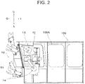
FIG. 2 is a diagram to illustrate an example of amain body 100 and adriver 10 of thecombination weighing apparatus 1 according to the first embodiment; -
FIG. 3 is a diagram to illustrate an example of the configuration of thedriver 10 in a state of attachment to themain body 100 of thecombination weighing apparatus 1 according to the first embodiment; -
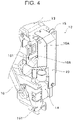
FIG. 4 is a diagram to illustrate an example of arrangement of abracket 15, afirst substrate 15A, and asecond substrate 15B of thedriver 10 of thecombination weighing apparatus 1 according to the first embodiment; -
FIG. 5 is a diagram to illustrate an example of aload cell 12 in thedriver 10 of thecombination weighing apparatus 1 according to the first embodiment; -
FIG. 6 is a diagram to illustrate an example of aferrite core 17 in thedriver 10 of thecombination weighing apparatus 1 according to the first embodiment; -
FIG. 7 is a diagram illustrating an example of a vertical orientation of thedriver 10 of thecombination weighing apparatus 1 according to the first embodiment; and -
FIG. 8 is a diagram illustrating an example of a horizontal orientation of thedriver 10 of thecombination weighing apparatus 1 according to the first embodiment. - Hereinafter, the present embodiment will be described in detail with reference to the attached drawings. In the following description of the drawings, the same or similar parts are denoted by the same or similar reference symbols. However, note that the drawings are schematic, and ratios of dimensions are different from actual ones. Therefore, specific dimensions and the like are determined in consideration of the following description. Moreover, there may be portions where dimensional relationships or proportions are different among the drawings. In this specification and the drawings, elements having substantially the same function and configuration are denoted by the same reference numerals to omit redundant description, and elements not directly related to the present invention are omitted.
- A
combination weighing apparatus 1 according to a first embodiment of the present invention will be described hereinbelow with reference toFIGS. 1 to 8 . - As illustrated in
FIG. 1 , thecombination weighing apparatus 1 according to this embodiment has a dispersion table 20, aradiation feeder 30, a flow rate regulation portion 40, asupport portion 50, apool hopper 60, aweighing hopper 70, achute 80, and atiming hopper 90. - The dispersion table 20 may also be configured to disperse a good that has been inserted from the outside while supplying the good to a plurality of
radiation feeders 30 arranged around the dispersion table 20. - The plurality of
radiation feeders 30 are each configured to convey, to thepool hopper 60 provided for eachradiation feeder 30, the good supplied from the dispersion table 20. - Note that, although not illustrated in this embodiment, a booster hopper may also be arranged downstream of the weighing
hopper 70 and upstream of thechute 80. - Furthermore, the
radiation feeders 30 each have a conveyance path for conveying goods, and the flow rate regulation portion 40 is arranged on the conveyance path. The flow rate regulation portion 40 is configured to regulate the flow rate of the goods conveyed to thepool hopper 60. In addition, thesupport portion 50 is configured to support the flow rate regulation portion 40. - The
pool hopper 60 is configured to deliver the goods supplied from theradiation feeder 30 to the weighinghopper 70, which is arranged below each pool hopper 60. - Each weighing
hopper 70 is configured to acquire the weight value of the goods that are received from eachpool hopper 60 and temporarily accumulated. - Here, the control unit (not illustrated) is configured to select a combination of the weight values acquired by each weighing hopper which is within a predetermined allowable range and closest to the target value, and to discharge the temporarily accumulated goods from the weighing
hopper 70 corresponding to the combination into achute 80 arranged below the weighinghopper 70. - Here, each
pool hopper 60 corresponds to a first hopper that temporarily stores goods to be inserted from outside and then discharges such goods downstream, and each weighinghopper 70 corresponds to a second hopper that temporarily stores the goods discharged from each pool hopper 60 (first hopper) and then discharges such goods downstream. - The
chute 80 is configured to supply the goods discharged from each weighinghopper 70 to thetiming hopper 90. - The
timing hopper 90 is configured to supply the goods supplied by the chute to, for example, a bag-making and packaging machine which is installed in a subsequent stage of thecombination weighing apparatus 1. - Furthermore, as illustrated in
FIG. 2 , thecombination weighing apparatus 1 according to the present embodiment has a plurality ofdrivers 10 that drive eachpool hopper 60 and each weighinghopper 70, and amain body 100 to whichsuch drivers 10 are attached. - Note that, as illustrated in
FIG. 2 , each of thedrivers 10 is configured to be attached to themain body 100 by being inserted into an opening 100A provided in the lateral surface of themain body 100, in a direction from an outer side O toward an inner side I of themain body 100. - In such a
combination weighing apparatus 1, the height-direction dimension of the components (internal components) of thedriver 10 that are arranged further on the inner side I than the opening 100A provided in the lateral surface of themain body 100 is larger than the height-direction dimension of this opening 10A. It is thus possible to attach thedriver 10 to the lateral surface of themain body 100 by inserting the internal components into the opening 100A of themain body 100 such that thedriver 10 is inclined relative to the opening 100A. - As illustrated in
FIG. 3 , thedriver 100 is provided with abase 11, aload cell 12, asecond motor 13, afirst motor 14, a first-hopper link member 16, afirst hopper hanger 60A, and asecond hopper hanger 70A. - The
base 11 is configured to block the opening 100A and separate the inner side I from the outer side O of themain body 100 in a state where thedriver 10 is attached to themain body 100. - The
first hopper hanger 60A is configured such that thepool hopper 60 is attached to the distal end of thefirst hopper hanger 60A, and thesecond hopper hanger 70A is configured such that the weighinghopper 70 is attached to the distal end of thesecond hopper hanger 70A. - The
first motor 14 is configured to drive the pool hopper 60 (and thefirst hopper hanger 60A), and thesecond motor 13 is configured to drive the weighing hopper 70 (and thesecond hopper hanger 70A). - The
load cell 12 is configured to detect the weight of the goods stored in the weighinghopper 70. - The first-
hopper link member 16 is a member that links thefirst motor 14 to thefirst hopper hanger 60A. - As illustrated in
FIGS. 2 and3 , thefirst motor 14, thesecond motor 13, and theload cell 12 are arranged on the inner side of themain body 100 in relation to thebase 11. - Furthermore, as illustrated in
FIG. 2 , at least a portion of thefirst motor 14,second motor 13, andload cell 12 are located further on a lower side L than a lower edge E1 of the opening 100A in a state where thedriver 10 is attached to themain body 100. In the example of FIG.
2, in such a state, thefirst motor 14 is located further on the lower side L than the lower edge E1 of the opening 100A. - According to such a configuration, the height-direction dimension of the opening 100A can be reduced, thus improving water resistance.
- As illustrated in
FIGS. 2 and3 , thefirst motor 14, thesecond motor 13, and theload cell 12 are arranged in a state of alignment in an up-down direction U/L. In the examples ofFIGS. 2 and3 , thesecond motor 13, theload cell 12, and thefirst motor 14 are arranged in a state of alignment in that order, starting from the upper side U.
In other words, thesecond motor 13 is arranged further on the upper side U than theload cell 12, and theload cell 12 is arranged further on the upper side U than thefirst motor 14. - Here, among the
first motor 14, thesecond motor 13, and theload cell 12, at least the member arranged lowermost on the lower side L is arranged offset on the inner side I of themain body 100 relative to other members. In the examples ofFIGS. 2 and3 , thefirst motor 14 is arranged offset to the inner side I of themain body 100 relative to thesecond motor 13 andload cell 12. - According to this configuration, because the
first motor 14 is not arranged directly under theload cell 12, the effect of the heat generated by thefirst motor 14 on theload cell 12 is reduced, and the weighing accuracy can be improved. - In addition, as illustrated in
FIG. 4 , thedriver 10 may be further provided with abracket 15, afirst substrate 15A, and asecond substrate 15B. - The
bracket 15 is arranged further on the inner side I of themain body 100 than thesecond motor 13 and is fixed to the weighinghopper 70, as illustrated inFIG. 3 . - For example, the
first substrate 15A is the driver substrate of a stepping motor for opening and closing thepool hopper 60 and the weighinghopper 70, and thesecond substrate 15B has an open-close control and preamble circuit for thepool hopper 60 and the weighinghopper 70. - The
substrate 15B is arranged further on the outer side O of themain body 100 than thefirst substrate 15A, as illustrated inFIGS. 3 and4 . - As illustrated in
FIGS. 3 and4 , thefirst substrate 15A andsecond substrate 15B are fixed to thebracket 15 in a state where their respective back surfaces are facing each other. - Furthermore, as illustrated in
FIG. 3 , thefirst substrate 15A and thesecond substrate 15B are arranged further on the inner side I of themain body 100 than thesecond motor 13 and theload cell 12, and are arranged further on the upper side U than thefirst motor 14. Here, as illustrated inFIG. 4 , thesecond substrate 15B is arranged on the back surface (inner side I) of thesecond motor 13. - According to such a configuration, by arranging the
first substrate 15A and thesecond substrate 15B as described above, it is possible to fit the internal components of thedriver 10 into a minimum space, which has the effect of eliminating the need to increase the size of themain body 100. - As illustrated in
FIG. 5 , theload cell 12 has an upper and lower pair ofparallel beams 12A, each provided with a thin-walled portion (notch) 12B at two front and rear locations in the longitudinal direction. - Here, as illustrated in
FIG. 3 , the thin-walled portion 12B provided on the upper-side Uparallel beam 12A and/or the thin-walled portion 12B provided on the lower-side Lparallel beam 12A is arranged so as to not overlap a first-hopper link member 18 in a horizontal view. - In the example of
FIG. 3 , the thin-walled portion 12B provided on the upper-side Uparallel beam 12A is arranged so as to not overlap the first-hopper link member 18 in a horizontal view. More specifically, the first-hopper link member 18 has a crank shape as illustrated inFIG. 3 . - Here, as illustrated in
FIG. 3 , thebase 11 is inclined with respect to the vertical direction so that the upper end UE is located more on the outer side O of themain body 100 than the lower end LE. - Normally, in order to adjust the off-center characteristic of the
combination weighing apparatus 1, four corner adjustment is performed by using a file or the like to shave the area close to the end surface of the thin-walled portion 12B. Therefore, in the case of thiscombination weighing apparatus 1, access to the thin-walled portion 12B is required. - In this regard, according to the foregoing configuration, the
base 11 is inclined, and the first-hopper link member 18 has a crank shape, as illustrated inFIG. 3 , and therefore the thin-walled portion 12B provided on the upper-side Uparallel beam 12A is exposed without overlapping other members in a horizontal view. As a result, access to the thin-walled portion 12B is easy during the four corner adjustment, which affords the advantageous effects of improving the workability of four corner adjustment and reducing man-hours, leading to reduced costs. - As illustrated in
FIGS. 2 and6 , thedriver 10 may further include aferrite core 17 attached to aharness 17A and aload cell bracket 18 fixed to theload cell 12. - Here, the
ferrite core 17 is a ferrite core for noise rejection that is attached to theharness 17A between theload cell 12 and thefirst substrate 15A. - As illustrated in
FIG. 6 , theferrite core 17 is supported by using, as points of support, the back surface of thefirst substrate 15A (position A inFIG. 6 ), abottom plate 15C (position B inFIG. 6 ) provided on the lower edge of thebracket 15, and aprotrusion 18A (position C inFIG. 6 ) on the lateral surface of theload cell bracket 18. - More specifically, as illustrated in
FIG. 6 , theferrite core 17 is supported at three points as described above, and is fixed by being held down by thesubstrate cover 19. In addition, because the length of theharness 17A between theload cell 12 and thefirst substrate 15A is short, theferrite core 17 is pulled clockwise with the above-mentionedprotrusion 18A and thebottom plate 15C serving as the fulcrum, as illustrated inFIG. 6 , and thus the position of theferrite core 17 is uniquely determined. - According to such a configuration, the position of the
ferrite core 17 is then clear, and the operator is thus able to assemble theferrite core 17 without thinking. In addition, such a configuration makes it possible to eliminate variations in the assembly of theferrite core 17 because same is not dependent on the assembly method of the operator, thus shortening the man-hours and also reducing costs. - As illustrated in
FIGS. 2 and7 , thedriver 10 may further include asubstrate cover 19 that covers the inner side I of themain body 100 of thefirst substrate 15A, and a weighing-time sensing unit 102. - The weighing-
time sensing unit 102 is connected to the free end side of theload cell 12, and the weighing of goods can be performed by placing the goods on the weighing-time sensing unit 102. - As illustrated in
FIG. 3 , in thecombination weighing apparatus 1 according to this embodiment, the weighing-time sensing unit 102 protrudes more toward the outside than the flange portion of thebase 11. - Here, as illustrated in
FIG. 7 , when thedriver 10 is placed such that the up-down direction of the driver 10 (vertical orientation) is inverted, the upper end of thefirst hopper hanger 60A and thesubstrate cover 19 are supported by grounding (G). - Furthermore, as illustrated in
FIG. 8 , thedriver 10 may further include asensor stopper 101 attached to the inner side I of themain body 100 of thefirst motor 14. - Here, as illustrated in
FIG. 8 , when thedriver 10 is placed such that the end of thedriver 10 in the width direction W is on the lower side (horizontal orientation), the end of the base 11 in the width direction W, the end of thesubstrate cover 19 in the width direction W, and the end of thesensor stopper 101 in the width direction W are supported by grounding (G). - According to this configuration, the
driver 10 itself can be afforded a vertical or horizontal orientation without placing a burden on the weighing-time sensing unit 102 even when the weighing-time sensing unit 102 protrudes more toward the outside than the flange portion of thebase 11 and the flange portion of thebase 11 is inclined relative to the vertical direction. - The
combination weighing apparatus 1 according to the present embodiment can improve water resistance and prevent the weighing accuracy from being degraded. - Although the present invention is explained in detail using the above-mentioned embodiments, it will be apparent to those skilled in the art that the present invention is not limited to the embodiments described herein. The present invention can be implemented as modifications and changes without departing from the spirit and scope of the present invention defined by the description of the claims. Accordingly, the description of the present specification is for the purpose of illustration and is not intended to limit the present invention in any way.
-
- 1
- combination weighing apparatus
- 10
- driver
- 11
- base
- 12
- load cell
- 12A
- parallel beams
- 12B
- thin-walled portion
- 13
- second motor
- 14
- first motor
- 15
- bracket
- 15A
- first substrate
- 15B
- second substrate
- 15C
- bottom plate
- 16
- first-hopper link member
- 17
- ferrite core
- 18
- first-hopper link member
- 18A
- protrusion
- 19
- substrate cover
- 20
- dispersion table
- 30
- radiation feeder
- 40
- flow rate regulation portion
- 50
- support portion
- 60
- pool hopper
- 60A
- first hopper hanger
- 70
- weighing hopper
- 70A
- second hopper hanger
- 80
- chute
- 90
- timing hopper
- 100
- main body
- 100A
- opening
- 101
- sensor stopper
- 102
- weighing-time sensing unit
Claims (7)
- A combination weighing apparatus, comprising:a first hopper that, after temporarily storing a good inserted from outside, discharges the good downstream;a second hopper that, after temporarily storing the good discharged from the first hopper, discharges the good downstream;a driver that drives the first hopper and the second hopper; anda main body to which the driver is attached, whereinthe driver is attached to the main body by being inserted into an opening provided in the lateral surface of the main body, in a direction from an outer side toward an inner side of the main body,the driver has:a base that blocks the opening and separates the inner side from the outer side of the main body in a state of being attached to the main body;a first motor that drives the first hopper;a second motor that drives the second hopper;
anda load cell that detects a weight of the good stored in the second hopper,the first motor, the second motor, and the load cell are arranged on the inner side of the main body in relation to the base, andin a state where the driver is attached to the main body, at least a portion of the first motor, the second motor, and the load cell is located further on a lower side than the lower edge of the opening. - The combination weighing apparatus according to claim 1, whereinthe first motor, the second motor, and the load cell are arranged in a state of alignment in an up-down direction, andamong the first motor, the second motor, and the load cell, at least the member arranged on the lowermost side is arranged so as to be offset on the inner side of the main body relative to other members.
- The combination weighing apparatus according to claim 2, whereinthe second motor is arranged more on an upper side than the first motor,the driver further includes:a bracket that is arranged more on the inner side of the main body than the second motor and that is fixed to the second motor;a first substrate; anda second substrate that is arranged more on the outer side of the main body than the first substrate,the first substrate and the second substrate are fixed to the bracket in a state where the respective back surfaces thereof face each other, andthe first substrate and the second substrate are arranged more on the inner side of the main body than the second motor and the load cell, and are arranged more on the upper side than the first motor.
- The combination weighing apparatus according to claim 3, whereinthe second motor, the load cell, and the first motor are arranged in a state of alignment in that order, starting from the upper side,the driver further includes:a first hopper hanger to a distal end of which the first hopper is attached; anda first-hopper link member that links the first motor to the first hopper hanger,the load cell has an upper and lower pair of parallel beams that are each provided with a thin-walled portion at two front and rear locations in a longitudinal direction,the base is inclined relative to a vertical direction such that an upper end thereof is located further on the outer side of the main body than a lower end, andthe thin-walled portion provided to the upper-side parallel beam and/or the thin-walled portion provided to the lower-side parallel beam is arranged so as to not overlap the first-hopper link member in a horizontal view.
- The combination weighing apparatus according to claim 3 or 4, whereinthe driver further includes:a ferrite core that is attached to a harness;
anda load cell bracket that is attached to the load cell, andthe ferrite core is supported by taking, as points of support, the back surface of the first substrate, a bottom surface provided on the lower edge of the bracket, and a protrusion on the lateral surface of the load cell bracket. - The combination weighing apparatus according to claim 4, whereinthe driver further includes a substrate cover that covers the inner side of the main body of the first substrate, andwhen the driver is placed such that the up-down direction of the driver is inverted, the upper end of the first hopper hanger and the substrate cover are supported by grounding.
- The combination weighing apparatus according to claim 3 or 4, whereinthe driver further includes a sensor stopper attached to the inner side of the main body of the first motor, andwhen the driver is placed such that an end of the driver in a width direction is on the lower side, an end of the base in the width direction, an end of the bracket in the width direction, and an end of the sensor stopper in the width direction are supported by grounding.
Applications Claiming Priority (1)
| Application Number | Priority Date | Filing Date | Title |
|---|---|---|---|
| JP2020185844A JP7606205B2 (en) | 2020-11-06 | 2020-11-06 | Combination Weighing Device |
Publications (2)
| Publication Number | Publication Date |
|---|---|
| EP3995794A1 true EP3995794A1 (en) | 2022-05-11 |
| EP3995794B1 EP3995794B1 (en) | 2023-09-13 |
Family
ID=78676294
Family Applications (1)
| Application Number | Title | Priority Date | Filing Date |
|---|---|---|---|
| EP21205699.8A Active EP3995794B1 (en) | 2020-11-06 | 2021-10-29 | Combination weighing apparatus |
Country Status (5)
| Country | Link |
|---|---|
| US (1) | US11927471B2 (en) |
| EP (1) | EP3995794B1 (en) |
| JP (1) | JP7606205B2 (en) |
| CN (1) | CN114441013B (en) |
| DK (1) | DK3995794T3 (en) |
Cited By (1)
| Publication number | Priority date | Publication date | Assignee | Title |
|---|---|---|---|---|
| CN116930231A (en) * | 2023-09-15 | 2023-10-24 | 太原海通智慧信息技术有限公司 | Cement material component online detection system and online detection method thereof |
Citations (3)
| Publication number | Priority date | Publication date | Assignee | Title |
|---|---|---|---|---|
| JPS546381B2 (en) | 1974-07-18 | 1979-03-28 | ||
| US4844190A (en) * | 1988-05-03 | 1989-07-04 | Ishida Scales Manufacturing Company, Ltd. | Combinational weigher for multiple operations |
| EP2634546A1 (en) * | 2010-10-29 | 2013-09-04 | Yamato Scale Co., Ltd. | Combination scale |
Family Cites Families (15)
| Publication number | Priority date | Publication date | Assignee | Title |
|---|---|---|---|---|
| US4705125A (en) * | 1986-11-14 | 1987-11-10 | Ishida Scales Manufacturing Company, Ltd. | Method of and apparatus for controlling hopper gate motion |
| EP0362567B1 (en) * | 1988-09-07 | 1992-12-09 | Ishida Scales Mfg. Co., Ltd. | Waterproof automatic weighing apparatus |
| JPH02167434A (en) * | 1988-09-07 | 1990-06-27 | Ishida Scales Mfg Co Ltd | Water-proof type automatic weighing device |
| JP2525916Y2 (en) * | 1990-03-29 | 1997-02-12 | アンリツ株式会社 | Weighing device |
| JP3429326B2 (en) * | 1991-12-04 | 2003-07-22 | 大和製衡株式会社 | Hopper gate opening and closing device |
| JP3609533B2 (en) * | 1996-04-11 | 2005-01-12 | 株式会社イシダ | Weighing device |
| EP0852328B1 (en) * | 1996-07-03 | 2003-08-13 | ISHIDA CO., Ltd. | Measuring instrument improving fittability and removability of hopper |
| JP5858729B2 (en) * | 2011-10-28 | 2016-02-10 | 大和製衡株式会社 | Hopper opening and closing mechanism |
| JP6437274B2 (en) * | 2014-10-31 | 2018-12-12 | 株式会社イシダ | Article processing equipment |
| JP3197141U (en) * | 2015-02-09 | 2015-04-23 | 株式会社イシダ | Combination weighing device |
| JP6465760B2 (en) * | 2015-06-17 | 2019-02-06 | 大和製衡株式会社 | Combination scale |
| CN206459731U (en) * | 2017-01-22 | 2017-09-01 | 杭州中衡包装机械有限公司 | A kind of combination balance feeding device |
| JP6804764B2 (en) * | 2017-03-17 | 2020-12-23 | 株式会社イシダ | Combination weighing device |
| JP7061796B2 (en) * | 2018-08-31 | 2022-05-02 | 株式会社イシダ | Combination weighing device |
| JP7300706B2 (en) * | 2019-03-12 | 2023-06-30 | 株式会社イシダ | Combination weighing device and stand for combination weighing device |
-
2020
- 2020-11-06 JP JP2020185844A patent/JP7606205B2/en active Active
-
2021
- 2021-10-29 EP EP21205699.8A patent/EP3995794B1/en active Active
- 2021-10-29 DK DK21205699.8T patent/DK3995794T3/en active
- 2021-11-02 US US17/517,350 patent/US11927471B2/en active Active
- 2021-11-05 CN CN202111305678.7A patent/CN114441013B/en active Active
Patent Citations (4)
| Publication number | Priority date | Publication date | Assignee | Title |
|---|---|---|---|---|
| JPS546381B2 (en) | 1974-07-18 | 1979-03-28 | ||
| US4844190A (en) * | 1988-05-03 | 1989-07-04 | Ishida Scales Manufacturing Company, Ltd. | Combinational weigher for multiple operations |
| EP2634546A1 (en) * | 2010-10-29 | 2013-09-04 | Yamato Scale Co., Ltd. | Combination scale |
| JP5406381B2 (en) * | 2010-10-29 | 2014-02-05 | 大和製衡株式会社 | Combination scale |
Cited By (2)
| Publication number | Priority date | Publication date | Assignee | Title |
|---|---|---|---|---|
| CN116930231A (en) * | 2023-09-15 | 2023-10-24 | 太原海通智慧信息技术有限公司 | Cement material component online detection system and online detection method thereof |
| CN116930231B (en) * | 2023-09-15 | 2023-11-24 | 太原海通智慧信息技术有限公司 | Cement material component online detection system and online detection method thereof |
Also Published As
| Publication number | Publication date |
|---|---|
| US11927471B2 (en) | 2024-03-12 |
| CN114441013A (en) | 2022-05-06 |
| JP7606205B2 (en) | 2024-12-25 |
| CN114441013B (en) | 2024-08-23 |
| DK3995794T3 (en) | 2023-10-02 |
| JP2022075204A (en) | 2022-05-18 |
| US20220146302A1 (en) | 2022-05-12 |
| EP3995794B1 (en) | 2023-09-13 |
Similar Documents
| Publication | Publication Date | Title |
|---|---|---|
| EP3995794B1 (en) | Combination weighing apparatus | |
| EP3617671B1 (en) | Combination weighing device | |
| EP3098580B1 (en) | Combination weighing apparatus | |
| US10981681B2 (en) | Filling/sealing device for container | |
| CN112204361B (en) | Combined metering device | |
| US11927470B2 (en) | Combination weighing apparatus with discharge chute including slide surface | |
| CA2431479A1 (en) | A system for feeding portions of material to an injection molding machine | |
| US11975923B2 (en) | Article retaining device and supporting body | |
| CN106865167B (en) | Parts feeder | |
| EP3598085A1 (en) | Combination weighing device | |
| US20090234487A1 (en) | Assembly system | |
| JP7586726B2 (en) | Weight Checker | |
| EP3995793A1 (en) | Article conveying apparatus | |
| CN114014046A (en) | A kind of automatic control method and system of sheet conveying | |
| US11274959B2 (en) | Weighing apparatus and combination weighing apparatus | |
| JP2022075209A (en) | Combination weighing device | |
| JP2889334B2 (en) | Bucket conveyor article supply device | |
| US6502684B2 (en) | Selection and supply device for cylindrical-type products | |
| KR19980030930U (en) | Guide device of chain conveyor | |
| CN111846732B (en) | Non-contact self-service medicine taking machine for hospital | |
| CN210555726U (en) | Material packaging system | |
| CN210655116U (en) | Cigarette lifting machine | |
| JP7232848B2 (en) | tape feeder | |
| WO2025070671A1 (en) | Transport device, and weighing and serving system | |
| KR20200001528A (en) | Tray feeder |
Legal Events
| Date | Code | Title | Description |
|---|---|---|---|
| PUAI | Public reference made under article 153(3) epc to a published international application that has entered the european phase |
Free format text: ORIGINAL CODE: 0009012 |
|
| STAA | Information on the status of an ep patent application or granted ep patent |
Free format text: STATUS: REQUEST FOR EXAMINATION WAS MADE |
|
| 17P | Request for examination filed |
Effective date: 20211029 |
|
| AK | Designated contracting states |
Kind code of ref document: A1 Designated state(s): AL AT BE BG CH CY CZ DE DK EE ES FI FR GB GR HR HU IE IS IT LI LT LU LV MC MK MT NL NO PL PT RO RS SE SI SK SM TR |
|
| GRAP | Despatch of communication of intention to grant a patent |
Free format text: ORIGINAL CODE: EPIDOSNIGR1 |
|
| STAA | Information on the status of an ep patent application or granted ep patent |
Free format text: STATUS: GRANT OF PATENT IS INTENDED |
|
| INTG | Intention to grant announced |
Effective date: 20230414 |
|
| GRAS | Grant fee paid |
Free format text: ORIGINAL CODE: EPIDOSNIGR3 |
|
| GRAA | (expected) grant |
Free format text: ORIGINAL CODE: 0009210 |
|
| STAA | Information on the status of an ep patent application or granted ep patent |
Free format text: STATUS: THE PATENT HAS BEEN GRANTED |
|
| AK | Designated contracting states |
Kind code of ref document: B1 Designated state(s): AL AT BE BG CH CY CZ DE DK EE ES FI FR GB GR HR HU IE IS IT LI LT LU LV MC MK MT NL NO PL PT RO RS SE SI SK SM TR |
|
| REG | Reference to a national code |
Ref country code: CH Ref legal event code: EP |
|
| REG | Reference to a national code |
Ref country code: DK Ref legal event code: T3 Effective date: 20230926 |
|
| REG | Reference to a national code |
Ref country code: DE Ref legal event code: R096 Ref document number: 602021005115 Country of ref document: DE |
|
| REG | Reference to a national code |
Ref country code: IE Ref legal event code: FG4D |
|
| REG | Reference to a national code |
Ref country code: LT Ref legal event code: MG9D |
|
| REG | Reference to a national code |
Ref country code: NL Ref legal event code: MP Effective date: 20230913 |
|
| PG25 | Lapsed in a contracting state [announced via postgrant information from national office to epo] |
Ref country code: GR Free format text: LAPSE BECAUSE OF FAILURE TO SUBMIT A TRANSLATION OF THE DESCRIPTION OR TO PAY THE FEE WITHIN THE PRESCRIBED TIME-LIMIT Effective date: 20231214 |
|
| PG25 | Lapsed in a contracting state [announced via postgrant information from national office to epo] |
Ref country code: SE Free format text: LAPSE BECAUSE OF FAILURE TO SUBMIT A TRANSLATION OF THE DESCRIPTION OR TO PAY THE FEE WITHIN THE PRESCRIBED TIME-LIMIT Effective date: 20230913 Ref country code: RS Free format text: LAPSE BECAUSE OF FAILURE TO SUBMIT A TRANSLATION OF THE DESCRIPTION OR TO PAY THE FEE WITHIN THE PRESCRIBED TIME-LIMIT Effective date: 20230913 Ref country code: NO Free format text: LAPSE BECAUSE OF FAILURE TO SUBMIT A TRANSLATION OF THE DESCRIPTION OR TO PAY THE FEE WITHIN THE PRESCRIBED TIME-LIMIT Effective date: 20231213 Ref country code: LV Free format text: LAPSE BECAUSE OF FAILURE TO SUBMIT A TRANSLATION OF THE DESCRIPTION OR TO PAY THE FEE WITHIN THE PRESCRIBED TIME-LIMIT Effective date: 20230913 Ref country code: LT Free format text: LAPSE BECAUSE OF FAILURE TO SUBMIT A TRANSLATION OF THE DESCRIPTION OR TO PAY THE FEE WITHIN THE PRESCRIBED TIME-LIMIT Effective date: 20230913 Ref country code: HR Free format text: LAPSE BECAUSE OF FAILURE TO SUBMIT A TRANSLATION OF THE DESCRIPTION OR TO PAY THE FEE WITHIN THE PRESCRIBED TIME-LIMIT Effective date: 20230913 Ref country code: GR Free format text: LAPSE BECAUSE OF FAILURE TO SUBMIT A TRANSLATION OF THE DESCRIPTION OR TO PAY THE FEE WITHIN THE PRESCRIBED TIME-LIMIT Effective date: 20231214 Ref country code: FI Free format text: LAPSE BECAUSE OF FAILURE TO SUBMIT A TRANSLATION OF THE DESCRIPTION OR TO PAY THE FEE WITHIN THE PRESCRIBED TIME-LIMIT Effective date: 20230913 |
|
| REG | Reference to a national code |
Ref country code: AT Ref legal event code: MK05 Ref document number: 1611727 Country of ref document: AT Kind code of ref document: T Effective date: 20230913 |
|
| PG25 | Lapsed in a contracting state [announced via postgrant information from national office to epo] |
Ref country code: NL Free format text: LAPSE BECAUSE OF FAILURE TO SUBMIT A TRANSLATION OF THE DESCRIPTION OR TO PAY THE FEE WITHIN THE PRESCRIBED TIME-LIMIT Effective date: 20230913 |
|
| PG25 | Lapsed in a contracting state [announced via postgrant information from national office to epo] |
Ref country code: IS Free format text: LAPSE BECAUSE OF FAILURE TO SUBMIT A TRANSLATION OF THE DESCRIPTION OR TO PAY THE FEE WITHIN THE PRESCRIBED TIME-LIMIT Effective date: 20240113 |
|
| PG25 | Lapsed in a contracting state [announced via postgrant information from national office to epo] |
Ref country code: AT Free format text: LAPSE BECAUSE OF FAILURE TO SUBMIT A TRANSLATION OF THE DESCRIPTION OR TO PAY THE FEE WITHIN THE PRESCRIBED TIME-LIMIT Effective date: 20230913 |
|
| PG25 | Lapsed in a contracting state [announced via postgrant information from national office to epo] |
Ref country code: ES Free format text: LAPSE BECAUSE OF FAILURE TO SUBMIT A TRANSLATION OF THE DESCRIPTION OR TO PAY THE FEE WITHIN THE PRESCRIBED TIME-LIMIT Effective date: 20230913 |
|
| PG25 | Lapsed in a contracting state [announced via postgrant information from national office to epo] |
Ref country code: SM Free format text: LAPSE BECAUSE OF FAILURE TO SUBMIT A TRANSLATION OF THE DESCRIPTION OR TO PAY THE FEE WITHIN THE PRESCRIBED TIME-LIMIT Effective date: 20230913 Ref country code: RO Free format text: LAPSE BECAUSE OF FAILURE TO SUBMIT A TRANSLATION OF THE DESCRIPTION OR TO PAY THE FEE WITHIN THE PRESCRIBED TIME-LIMIT Effective date: 20230913 Ref country code: IT Free format text: LAPSE BECAUSE OF NON-PAYMENT OF DUE FEES Effective date: 20231029 Ref country code: IS Free format text: LAPSE BECAUSE OF FAILURE TO SUBMIT A TRANSLATION OF THE DESCRIPTION OR TO PAY THE FEE WITHIN THE PRESCRIBED TIME-LIMIT Effective date: 20240113 Ref country code: ES Free format text: LAPSE BECAUSE OF FAILURE TO SUBMIT A TRANSLATION OF THE DESCRIPTION OR TO PAY THE FEE WITHIN THE PRESCRIBED TIME-LIMIT Effective date: 20230913 Ref country code: EE Free format text: LAPSE BECAUSE OF FAILURE TO SUBMIT A TRANSLATION OF THE DESCRIPTION OR TO PAY THE FEE WITHIN THE PRESCRIBED TIME-LIMIT Effective date: 20230913 Ref country code: CZ Free format text: LAPSE BECAUSE OF FAILURE TO SUBMIT A TRANSLATION OF THE DESCRIPTION OR TO PAY THE FEE WITHIN THE PRESCRIBED TIME-LIMIT Effective date: 20230913 Ref country code: AT Free format text: LAPSE BECAUSE OF FAILURE TO SUBMIT A TRANSLATION OF THE DESCRIPTION OR TO PAY THE FEE WITHIN THE PRESCRIBED TIME-LIMIT Effective date: 20230913 Ref country code: PT Free format text: LAPSE BECAUSE OF FAILURE TO SUBMIT A TRANSLATION OF THE DESCRIPTION OR TO PAY THE FEE WITHIN THE PRESCRIBED TIME-LIMIT Effective date: 20240115 Ref country code: SK Free format text: LAPSE BECAUSE OF FAILURE TO SUBMIT A TRANSLATION OF THE DESCRIPTION OR TO PAY THE FEE WITHIN THE PRESCRIBED TIME-LIMIT Effective date: 20230913 |
|
| PG25 | Lapsed in a contracting state [announced via postgrant information from national office to epo] |
Ref country code: PL Free format text: LAPSE BECAUSE OF FAILURE TO SUBMIT A TRANSLATION OF THE DESCRIPTION OR TO PAY THE FEE WITHIN THE PRESCRIBED TIME-LIMIT Effective date: 20230913 |
|
| REG | Reference to a national code |
Ref country code: DE Ref legal event code: R097 Ref document number: 602021005115 Country of ref document: DE |
|
| REG | Reference to a national code |
Ref country code: BE Ref legal event code: MM Effective date: 20231031 |
|
| PG25 | Lapsed in a contracting state [announced via postgrant information from national office to epo] |
Ref country code: LU Free format text: LAPSE BECAUSE OF NON-PAYMENT OF DUE FEES Effective date: 20231029 |
|
| PG25 | Lapsed in a contracting state [announced via postgrant information from national office to epo] |
Ref country code: LU Free format text: LAPSE BECAUSE OF NON-PAYMENT OF DUE FEES Effective date: 20231029 |
|
| PG25 | Lapsed in a contracting state [announced via postgrant information from national office to epo] |
Ref country code: MC Free format text: LAPSE BECAUSE OF FAILURE TO SUBMIT A TRANSLATION OF THE DESCRIPTION OR TO PAY THE FEE WITHIN THE PRESCRIBED TIME-LIMIT Effective date: 20230913 |
|
| PLBE | No opposition filed within time limit |
Free format text: ORIGINAL CODE: 0009261 |
|
| STAA | Information on the status of an ep patent application or granted ep patent |
Free format text: STATUS: NO OPPOSITION FILED WITHIN TIME LIMIT |
|
| PG25 | Lapsed in a contracting state [announced via postgrant information from national office to epo] |
Ref country code: MC Free format text: LAPSE BECAUSE OF FAILURE TO SUBMIT A TRANSLATION OF THE DESCRIPTION OR TO PAY THE FEE WITHIN THE PRESCRIBED TIME-LIMIT Effective date: 20230913 |
|
| 26N | No opposition filed |
Effective date: 20240614 |
|
| PG25 | Lapsed in a contracting state [announced via postgrant information from national office to epo] |
Ref country code: BE Free format text: LAPSE BECAUSE OF NON-PAYMENT OF DUE FEES Effective date: 20231031 |
|
| PG25 | Lapsed in a contracting state [announced via postgrant information from national office to epo] |
Ref country code: IE Free format text: LAPSE BECAUSE OF NON-PAYMENT OF DUE FEES Effective date: 20231029 |
|
| PG25 | Lapsed in a contracting state [announced via postgrant information from national office to epo] |
Ref country code: FR Free format text: LAPSE BECAUSE OF NON-PAYMENT OF DUE FEES Effective date: 20231113 |
|
| PG25 | Lapsed in a contracting state [announced via postgrant information from national office to epo] |
Ref country code: SI Free format text: LAPSE BECAUSE OF FAILURE TO SUBMIT A TRANSLATION OF THE DESCRIPTION OR TO PAY THE FEE WITHIN THE PRESCRIBED TIME-LIMIT Effective date: 20230913 |
|
| PG25 | Lapsed in a contracting state [announced via postgrant information from national office to epo] |
Ref country code: SI Free format text: LAPSE BECAUSE OF FAILURE TO SUBMIT A TRANSLATION OF THE DESCRIPTION OR TO PAY THE FEE WITHIN THE PRESCRIBED TIME-LIMIT Effective date: 20230913 Ref country code: IE Free format text: LAPSE BECAUSE OF NON-PAYMENT OF DUE FEES Effective date: 20231029 Ref country code: FR Free format text: LAPSE BECAUSE OF NON-PAYMENT OF DUE FEES Effective date: 20231113 |
|
| PG25 | Lapsed in a contracting state [announced via postgrant information from national office to epo] |
Ref country code: BG Free format text: LAPSE BECAUSE OF FAILURE TO SUBMIT A TRANSLATION OF THE DESCRIPTION OR TO PAY THE FEE WITHIN THE PRESCRIBED TIME-LIMIT Effective date: 20230913 |
|
| PG25 | Lapsed in a contracting state [announced via postgrant information from national office to epo] |
Ref country code: BG Free format text: LAPSE BECAUSE OF FAILURE TO SUBMIT A TRANSLATION OF THE DESCRIPTION OR TO PAY THE FEE WITHIN THE PRESCRIBED TIME-LIMIT Effective date: 20230913 |
|
| PG25 | Lapsed in a contracting state [announced via postgrant information from national office to epo] |
Ref country code: IT Free format text: LAPSE BECAUSE OF NON-PAYMENT OF DUE FEES Effective date: 20231029 |
|
| PGRI | Patent reinstated in contracting state [announced from national office to epo] |
Ref country code: IT Effective date: 20231031 |
|
| PG25 | Lapsed in a contracting state [announced via postgrant information from national office to epo] |
Ref country code: IT Free format text: LAPSE BECAUSE OF NON-PAYMENT OF DUE FEES Effective date: 20231029 |
|
| PGRI | Patent reinstated in contracting state [announced from national office to epo] |
Ref country code: IT Effective date: 20231031 |
|
| REG | Reference to a national code |
Ref country code: CH Ref legal event code: PL |
|
| PG25 | Lapsed in a contracting state [announced via postgrant information from national office to epo] |
Ref country code: CH Free format text: LAPSE BECAUSE OF NON-PAYMENT OF DUE FEES Effective date: 20241031 |
|
| PG25 | Lapsed in a contracting state [announced via postgrant information from national office to epo] |
Ref country code: CY Free format text: LAPSE BECAUSE OF FAILURE TO SUBMIT A TRANSLATION OF THE DESCRIPTION OR TO PAY THE FEE WITHIN THE PRESCRIBED TIME-LIMIT; INVALID AB INITIO Effective date: 20211029 |
|
| PG25 | Lapsed in a contracting state [announced via postgrant information from national office to epo] |
Ref country code: TR Free format text: LAPSE BECAUSE OF FAILURE TO SUBMIT A TRANSLATION OF THE DESCRIPTION OR TO PAY THE FEE WITHIN THE PRESCRIBED TIME-LIMIT Effective date: 20230913 |
|
| PGFP | Annual fee paid to national office [announced via postgrant information from national office to epo] |
Ref country code: DE Payment date: 20251020 Year of fee payment: 5 |
|
| PGFP | Annual fee paid to national office [announced via postgrant information from national office to epo] |
Ref country code: GB Payment date: 20251024 Year of fee payment: 5 |
|
| PGFP | Annual fee paid to national office [announced via postgrant information from national office to epo] |
Ref country code: IT Payment date: 20251031 Year of fee payment: 5 Ref country code: DK Payment date: 20251023 Year of fee payment: 5 |
|
| PG25 | Lapsed in a contracting state [announced via postgrant information from national office to epo] |
Ref country code: HU Free format text: LAPSE BECAUSE OF FAILURE TO SUBMIT A TRANSLATION OF THE DESCRIPTION OR TO PAY THE FEE WITHIN THE PRESCRIBED TIME-LIMIT; INVALID AB INITIO Effective date: 20211029 |