EP3995216A1 - Method for operating pulverizing system, and method for manufacturing powder - Google Patents
Method for operating pulverizing system, and method for manufacturing powder Download PDFInfo
- Publication number
- EP3995216A1 EP3995216A1 EP20837697.0A EP20837697A EP3995216A1 EP 3995216 A1 EP3995216 A1 EP 3995216A1 EP 20837697 A EP20837697 A EP 20837697A EP 3995216 A1 EP3995216 A1 EP 3995216A1
- Authority
- EP
- European Patent Office
- Prior art keywords
- flow rate
- crusher
- powder
- extraction flow
- crushed material
- Prior art date
- Legal status (The legal status is an assumption and is not a legal conclusion. Google has not performed a legal analysis and makes no representation as to the accuracy of the status listed.)
- Pending
Links
Images



Classifications
-
- B—PERFORMING OPERATIONS; TRANSPORTING
- B02—CRUSHING, PULVERISING, OR DISINTEGRATING; PREPARATORY TREATMENT OF GRAIN FOR MILLING
- B02C—CRUSHING, PULVERISING, OR DISINTEGRATING IN GENERAL; MILLING GRAIN
- B02C15/00—Disintegrating by milling members in the form of rollers or balls co-operating with rings or discs
- B02C15/04—Mills with pressed pendularly-mounted rollers, e.g. spring pressed
-
- B—PERFORMING OPERATIONS; TRANSPORTING
- B02—CRUSHING, PULVERISING, OR DISINTEGRATING; PREPARATORY TREATMENT OF GRAIN FOR MILLING
- B02C—CRUSHING, PULVERISING, OR DISINTEGRATING IN GENERAL; MILLING GRAIN
- B02C23/00—Auxiliary methods or auxiliary devices or accessories specially adapted for crushing or disintegrating not provided for in preceding groups or not specially adapted to apparatus covered by a single preceding group
- B02C23/08—Separating or sorting of material, associated with crushing or disintegrating
- B02C23/10—Separating or sorting of material, associated with crushing or disintegrating with separator arranged in discharge path of crushing or disintegrating zone
- B02C23/12—Separating or sorting of material, associated with crushing or disintegrating with separator arranged in discharge path of crushing or disintegrating zone with return of oversize material to crushing or disintegrating zone
-
- B—PERFORMING OPERATIONS; TRANSPORTING
- B02—CRUSHING, PULVERISING, OR DISINTEGRATING; PREPARATORY TREATMENT OF GRAIN FOR MILLING
- B02C—CRUSHING, PULVERISING, OR DISINTEGRATING IN GENERAL; MILLING GRAIN
- B02C23/00—Auxiliary methods or auxiliary devices or accessories specially adapted for crushing or disintegrating not provided for in preceding groups or not specially adapted to apparatus covered by a single preceding group
- B02C23/18—Adding fluid, other than for crushing or disintegrating by fluid energy
- B02C23/20—Adding fluid, other than for crushing or disintegrating by fluid energy after crushing or disintegrating
- B02C23/22—Adding fluid, other than for crushing or disintegrating by fluid energy after crushing or disintegrating with recirculation of material to crushing or disintegrating zone
-
- B—PERFORMING OPERATIONS; TRANSPORTING
- B02—CRUSHING, PULVERISING, OR DISINTEGRATING; PREPARATORY TREATMENT OF GRAIN FOR MILLING
- B02C—CRUSHING, PULVERISING, OR DISINTEGRATING IN GENERAL; MILLING GRAIN
- B02C23/00—Auxiliary methods or auxiliary devices or accessories specially adapted for crushing or disintegrating not provided for in preceding groups or not specially adapted to apparatus covered by a single preceding group
- B02C23/18—Adding fluid, other than for crushing or disintegrating by fluid energy
- B02C23/24—Passing gas through crushing or disintegrating zone
- B02C23/34—Passing gas through crushing or disintegrating zone gas being recirculated to crushing or disintegrating zone
-
- B—PERFORMING OPERATIONS; TRANSPORTING
- B02—CRUSHING, PULVERISING, OR DISINTEGRATING; PREPARATORY TREATMENT OF GRAIN FOR MILLING
- B02C—CRUSHING, PULVERISING, OR DISINTEGRATING IN GENERAL; MILLING GRAIN
- B02C25/00—Control arrangements specially adapted for crushing or disintegrating
-
- B—PERFORMING OPERATIONS; TRANSPORTING
- B02—CRUSHING, PULVERISING, OR DISINTEGRATING; PREPARATORY TREATMENT OF GRAIN FOR MILLING
- B02C—CRUSHING, PULVERISING, OR DISINTEGRATING IN GENERAL; MILLING GRAIN
- B02C15/00—Disintegrating by milling members in the form of rollers or balls co-operating with rings or discs
- B02C2015/002—Disintegrating by milling members in the form of rollers or balls co-operating with rings or discs combined with a classifier
Definitions
- the present invention relates to a method of manufacturing powder manufactured by crushing crush raw meal with a vertical crusher and a method of operating a crushing system used in this manufacturing method.
- a vertical crusher is conventionally known as one of crushers that dry and crush the crush raw meal.
- Examples of the crush raw meal include cement raw meal and calcium carbonate.
- Each of PTLs 1 and 2 discloses a crushing system including this type of vertical crusher.
- PTL 1 discloses a closed circuit crushing type crushing system.
- the crushing system includes a vertical crusher in which a classifier is incorporated.
- a classifier When the crush raw meal is crushed by the crusher, crushed material containing coarse powder and fine powder is generated.
- the coarse powder is discharged from the crusher once, is supplied to the crusher again, and is crushed again.
- the fine powder passes through the classifier together with a gas flowing upward in the crusher and is classified by the classifier into refined powder and the other fine powder.
- the refined powder is discharged from the crusher together with the gas, is collected by a dust collector, and is recovered as a product.
- the gas separated from the refined powder by the dust collector is returned to the crusher.
- the crushing system of PTL 2 includes a classifier that is independent from the vertical crusher.
- the fine powder of the crushed material of the crusher is discharged from the crusher together with the gas extracted from the crusher and is separated from the gas by the dust collector.
- the gas separated from the fine powder by the dust collector is returned to the crusher, and the fine powder is conveyed to the classifier by a conveyor.
- the coarse powder of the crushed material of the crusher is conveyed to the classifier by the conveyor.
- the crushed material conveyed to the classifier is classified into the refined powder and the other material.
- the refined powder is recovered as a product by the dust collector disposed at a latter stage, and the other material is returned to the crusher.
- the present invention was made by further developing the invention described in PTL 2, and an object of the present invention is to provide a technique of manufacturing refined powder (powder) having arbitrarily adjusted fineness by using a closed circuit crushing system including a vertical crusher.
- a method of operating a crushing system is a method of operating a crushing system including: a vertical crusher that crushes crush raw meal; a crushed material circulating passage through which crushed material moves from a discharge port of the vertical crusher to a supply port of the vertical crusher; a classifier that is disposed at the crushed material circulating passage and classifies the crushed material into refined powder as a product and coarse powder to be returned to the vertical crusher; a collector that recovers the refined powder; an extraction passage connected to an upper portion of the vertical crusher; an extraction fan that extracts a gas from the vertical crusher to the extraction passage at a set extraction flow rate; and a dust collector that separates fine powder from the gas extracted from the vertical crusher and supplies the fine powder to the crushed material circulating passage.
- the method includes: acquiring a correlation between an extraction flow rate of the gas extracted from the vertical crusher and fineness of the refined powder to be recovered; based on the correlation, estimating an extraction flow rate at which desired fineness is obtained; and setting the extraction flow rate as the set extraction flow rate.
- a method of manufacturing powder includes: supplying crush raw meal to a vertical crusher and crushing the crush raw meal; extracting a gas from the vertical crusher at a set extraction flow rate to convey fine powder of crushed material by flow of the gas; separating the fine powder from the flow of the gas and conveying the fine powder to a classifier by a conveying device; conveying a residue of the crushed material to the classifier by the conveying device; classifying the crushed material into refined powder and coarse powder by the classifier in accordance with a set particle diameter; conveying the refined powder from the classifier to a collector by the flow of the gas and recovering the refined powder as a product by the collector; and returning the coarse powder from the classifier to the vertical crusher and crushing the coarse powder again.
- the method includes: acquiring a correlation between an extraction flow rate of the gas extracted from the vertical crusher and fineness of the refined powder to be recovered; based on the correlation, estimating an extraction flow rate at which desired fineness is obtained; and setting the extraction flow rate as the set extraction flow rate.
- the refined powder (powder) of any fineness can be obtained by changing the set extraction flow rate.
- powder products corresponding to intended purposes can be obtained by changing the fineness of the refined powder to be obtained. With this, the quality of the powder product can be improved.
- the present invention can provide a technique of manufacturing refined powder (powder) having arbitrarily adjusted fineness by using a closed circuit crushing system including a vertical crusher.
- FIG. 1 is a diagram showing an entire configuration of a crushing system 1 according to one embodiment of the present invention.
- the closed-circuit crushing system 1 shown in FIG. 1 includes: a vertical crusher 2 (hereinafter simply referred to as the "crusher 2"); a crushed material circulation system 3 connected to the crusher 2; and a gas circulation system 4 connected to the crusher 2.
- a vertical crusher 2 hereinafter simply referred to as the "crusher 2"
- a crushed material circulation system 3 connected to the crusher 2
- a gas circulation system 4 connected to the crusher 2.
- the crusher 2 includes a housing 21 that forms a crush chamber 20 in which crush raw meal is crushed.
- a rotating table 22 and crush rollers 23 are disposed in the housing 21.
- the rotating table 22 rotates about a vertical rotation axis.
- the crush rollers 23 are brought into pressure contact with the rotating table 22 by a pressurizing unit (not shown) to be rotated.
- a mill motor 24 and a reduction gear 25 are disposed under the housing 21.
- the mill motor 24 is a rotation driving source of the rotating table 22.
- the reduction gear 25 transmits the rotational power of the mill motor 24 to the rotating table 22.
- the crusher 2 does not include a classifier.
- a supply port 26 is disposed at an upper portion of the housing 21.
- the crush raw meal is introduced through the supply port 26 onto an upper surface of the rotating table 22.
- an extraction port 27 is disposed above the rotating table 22 and at the upper portion of the housing 21. Fine powder generated by crushing the crush raw meal is discharged through the extraction port 27 by the flow of the gas blowing upward.
- a discharge port 28 is disposed under the rotating table 22. Crushed material overflowing from an outer peripheral edge of the rotating table 22 is discharged through the discharge port 28 to an outside of the crusher 2.
- a hot gas blowing port 29 is disposed around an outer periphery of the rotating table 22. A hot gas blows upward from the hot gas blowing port 29 to an inside of the crush chamber 20.
- the crushed material circulation system 3 separates refined powder as a product from the crushed material discharged from the discharge port 28 of the crusher 2 and returns the crushed material, from which the refined powder is separated, to the crusher 2.
- the refined powder separated by the crushed material circulation system 3 is recovered as the product.
- the discharge port 28 of the crusher 2 is connected to a first inlet 31a of the conveying device 31 through a passage 30a.
- the conveying device 31 conveys the crushed material, put into the conveying device 31 through the first inlet 31a and a below-described second inlet 31b, upward and discharges the crushed material from an outlet 31c.
- the outlet 31c of the conveying device 31 is connected to the crushed material inlet 71 of the classifier 7 through a passage 30b.
- a distribution damper (not shown) may be disposed at the passage 30b connecting the conveying device 31 and the classifier 7. By the distribution damper, part of the crushed material may be directly conveyed to the supply port 26 of the crusher 2 without passing through the classifier 7.
- the classifier 7 classifies the supplied crushed material into refined powder and coarse powder in accordance with a set particle diameter.
- the set particle diameter of the "refined powder” is determined in accordance with the particle diameter of the product to be recovered.
- the "coarse powder” denotes powder having particle diameters larger than the particle diameter of the refined powder in the crushed material supplied to the classifier 7.
- a gas-flow classifier is adopted as the classifier 7.
- the classifier 7 is not limited to the gas-flow classifier as long as the classifier 7 can classify the crushed material into the refined powder and the other material in accordance with the particle diameter.
- the crushed material classified by the classifier 7 as the coarse powder is discharged from a discharge port 72.
- the discharge port 72 is connected to the supply port 26 of the crusher 2 through a passage 30c.
- the crushed material classified by the classifier 7 as the refined powder is discharged through an exhaust port 73 by the flow of the gas.
- the exhaust port 73 is connected to an inlet of a collector 6 through a passage 64.
- a classification fan 66 is disposed at an exhaust passage 65 of the collector 6. An exhaust flow rate of the classification fan 66 is adjusted to a predetermined classification flow rate F2.
- the collector 6 collects the refined powder flowing together with the gas discharged from the classifier 7 and separates the refined powder from the gas.
- a bug filter is adopted as the collector 6.
- the collector 6 is not limited to the bug filter as long as the collector 6 can collect the refined powder flowing together with the gas.
- the gas circulation system 4 separates the fine powder from an exhaust gas of the crusher 2 and returns the gas, from which the fine powder is separated, to the crusher 2 as the hot gas.
- the gas circulation system 4 includes a gas circulating passage 40 through which the gas extracted from the crusher 2 flows from the extraction port 27 of the crusher 2 to a hot gas inlet 29a of the crusher 2.
- a dust collector 41, an extraction fan 42, and a hot gas supply source 43 are disposed at the gas circulating passage 40.
- the dust collector 41 separates the fine powder from the gas extracted from the crusher 2.
- the hot gas supply source 43 supplies the hot gas to the gas circulating passage 40.
- the exhaust flow rate of the extraction fan 42 is adjusted to an extraction flow rate F1.
- the extraction port 27 of the crusher 2 is connected to an inlet of the dust collector 41 through an extraction passage 40a.
- An outlet of the dust collector 41 is connected to the hot gas inlet 29a of the crusher 2 through a passage 40b.
- the hot gas supply source 43 is connected to the passage 40b.
- the dust collector 41 separates the fine powder from the gas (hereinafter referred to as a "mill exhaust gas") extracted from the crusher 2.
- a cyclone dust collector that utilizes a suction action of the extraction fan 42 is adopted as the dust collector 41.
- the dust collector 41 is not limited to the cyclone dust collector as long as the dust collector 41 can separate the fine powder from the mill exhaust gas.
- a fine powder outlet of the dust collector 41 is connected to the second inlet 31b of the conveying device 31 through a conveyance passage 88 for the fine powder.
- the fine powder separated from the mill exhaust gas by the dust collector 41 is conveyed to the conveying device 31 through the conveyance passage 88.
- a passage 84 through which the mill exhaust gas of the passage 40b is supplied to the classifier 7 is connected to a portion of the passage 40b connected to an outlet of the dust collector 41, the portion being located downstream of the extraction fan 42 along the flow of the mill exhaust gas.
- a flow rate adjuster 85 that adjusts the flow rate of the mill exhaust gas flowing to the classifier 7 is disposed at the passage 84.
- the flow rate of the mill exhaust gas flowing to the classifier 7 can be adjusted by changing an opening degree of the flow rate adjuster 85. As a result, the flow rate of the mill exhaust gas returning to the crusher 2 can be adjusted.
- the flow rate adjuster 85 is not limited as long as the flow rate adjuster 85 adjusts the flow rate of the mill exhaust gas flowing to the classifier 7.
- the flow rate adjuster 85 may be at least one of a damper, a flow adjusting valve, and a fan.
- the hot gas supply source 43 may be, for example, a hot gas generating furnace that generates a hot gas having a desired temperature.
- the hot gas supplied from the hot gas supply source 43 to the gas circulating passage 40 is supplied to the hot gas inlet 29a of the crusher 2 through the passage 40b together with the mill exhaust gas.
- the hot gas supply source 43 is not limited to the hot gas generating furnace.
- a high-temperature gas generation source such as a kiln (cement firing furnace) exists around the crusher 2
- the high-temperature gas generation source may be utilized as the hot gas supply source 43.
- a method of operating the crushing system 1 configured as above and a method of manufacturing the powder by using the crushing system 1 will be described.
- the inside of the crush chamber 20 including the rotating table 22 and the crush rollers 23 is preheated by the hot gas blowing from the hot gas blowing port 29.
- the rotating table 22 is rotated by the mill motor 24, and the crush rollers 23 are rotated since peripheral surfaces of the crush rollers 23 are pressed against a crushing surface (upper surface) of the rotating table 22.
- the crush raw meal is supplied through the supply port 26 onto the rotating table 22 that is rotating as above.
- the crush raw meal is crushed between the rotating table 22 and the crush rollers 23.
- the coarse powder of the crushed material overflows from the peripheral edge of the rotating table 22 and is discharged through the discharge port 28 to the outside of the crusher 2.
- the fine powder of the crushed material is discharged from the extraction port 27 by the flow of the gas blowing upward.
- the fine powder flowing together with the mill exhaust gas is separated from the mill exhaust gas.
- the separated fine powder is conveyed through the conveyance passage 88 to the second inlet 31b of the conveying device 31 and joins the flow of the crushed material of the crushed material circulation system 3.
- the opening degree of the flow rate adjuster 85 is adjusted to adjust balance between the flow rate of the mill exhaust gas flowing into the passage 40b by the suction action of the extraction fan 42 and the flow rate of the mill exhaust gas returning to the crusher 2.
- the hot gas supplied from the hot gas supply source 43 to the passage 40b flows into the crusher 2 together with the mill exhaust gas and blows from the hot gas blowing port 29 into a mill.
- the crushed material discharged from the discharge port 28 of the crusher 2 is conveyed upward by the conveying device 31 and flows into the classifier 7.
- the crushed material is classified, and the refined powder is separated from the crushed material.
- the crushed material from which the refined powder is separated by the classifier 7 is discharged from the classifier 7, is supplied through the passage 30c to the supply port 26 of the crusher 2, and is crushed again by the crusher 2.
- the refined powder separated from the crushed material by the classifier 7 is discharged from the exhaust port 73 of the classifier 7 together with the gas and is conveyed through the passage 64 to the collector 6 by the flow of the gas.
- the collector 6 the refined powder is collected.
- the refined powder is recovered as the product and is, for example, bagged.
- the gas separated from the refined powder by the collector 6 flows out to the exhaust passage 65 to be discharged to the atmosphere.
- the fineness (degree of fineness of particles) of the refined powder recovered as the product as above is one of important factors that represent the quality of the refined powder.
- the fineness of the refined powder to be obtained can be changed by adjusting the extraction flow rate F1.
- the following verification experiments were performed to verify that the fineness of the refined powder can be adjusted by adjusting the extraction flow rate F1.
- the first experimental device simulates the crushing system 1 shown in FIG. 1 , and a detailed explanation thereof is omitted.
- Experiments of Examples 1 to 4 were performed by using the first experimental device.
- Experimental conditions in Examples 1 to 4 and Comparative Example 1 are shown in Table 1.
- the classification flow rate F2 was maintained constant at 15 [m 3 /min].
- the extraction flow rate F1 in Example 1 was 0 [m 3 /min]
- the extraction flow rate F1 in Example 2 was 3 [m 3 /min].
- the extraction flow rate F1 in Example 3 was 6 [m 3 /min]
- the extraction flow rate F1 in Example 4 was 9 [m 3 /min].
- the extraction flow rate F1 is the exhaust flow rate of the extraction fan 42
- the classification flow rate F2 is the exhaust flow rate of the classification fan 66.
- FIG. 2 is a diagram showing the configuration of the second experimental device 101.
- the second experimental device 101 includes: a vertical crusher 102; a collector 106 connected to an exhaust port 127 of the crusher 102; and a classification fan 166 that sucks an exhaust gas of the crusher 102 into the collector 106.
- the crusher 102 includes: a housing 121 that forms a crush chamber 120; a rotating table 122 that rotates about a vertical rotation axis; crush rollers 123 that are brought into pressure contact with the rotating table 122 by a pressurizing unit (not shown) to be rotated; a mill motor 124 that is a rotation driving source of the rotating table 122; a reduction gear 125 that transmits the rotational power of the mill motor 124 to the rotating table 122; and a classifier 107 disposed in the housing 121 so as to be located above the crush rollers 123.
- the crush raw meal supplied onto the rotating table 122 that is rotating is crushed between the rotating table 22 and the crush rollers 23 while being dried by the hot gas.
- the fine powder of the crushed material is carried to the classifier 107 by the flow of the gas blowing upward from a lower side and is classified into the refined powder and the other fine powder by the classifier 107.
- the refined powder is discharged from the exhaust port 127 by the flow of the gas and is recovered by the collector 106.
- the other fine powder classified by the classifier 107 as the fine powder other than the refined powder and the coarse powder having overflowed from the peripheral edge of the rotating table 122 are discharged to an outside of the crusher 102 once and are supplied to the crusher 102 again together with the new crush raw meal.
- Comparative Example 1 The experiment of Comparative Example 1 was performed by using the second experimental device 101 configured as above.
- the classification flow rate F2 was maintained constant at 15 [m 3 /min].
- the classification flow rate F2 is the flow rate of the classification fan 166.
- the second experimental device 101 since the extraction flow rate of the gas (flow rate of the exhaust gas) extracted from the crusher 102 is directly influenced by the classification flow rate F2, it is difficult to adjust only the extraction flow rate.
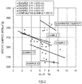
- FIG. 3 is a graph showing a correlation between the extraction flow rate F1 of the gas extracted from the crusher 2 and the fineness of the refined powder to be recovered.
- a vertical axis represents the specific surface area [cm 2 /g]
- a horizontal axis represents the 45 ⁇ R [%].
- Results of a fineness test of the refined powder obtained in Examples 1 to 4 and Comparative Example 1 are plotted in FIG. 3 .
- the specific surface area decreases as the 45 ⁇ R increases.
- the specific surface area decreases as the extraction flow rate F1 increases.
- the specific surface area is influenced by the fine powder in the refined powder. According to the above result in which when focusing on a certain value of the 45 ⁇ R, the specific surface area decreases as the extraction flow rate F1 increases, it is clear that: the fine powder decreases as the extraction flow rate F1 increases; and a fineness distribution is sharp, and the width of the distribution is narrow. In other words, the fineness (specific surface area) of the refined powder can be adjusted by adjusting the extraction flow rate F1.
- Examples 1 to 4 and Comparative Example 1 electric power consumption rates in the manufacture of the refined powder were measured. As the electric power consumption rates, electric power consumption rates of the mill motors 24 and 124 were measured. Most of the electric power consumption rate in the manufacture of the refined powder is the electric power consumption rate of the mill motor 24, 124.
- FIG. 4 is a graph showing a characteristic curve of the electric power consumption rate of the crusher 2 with respect to the extraction flow rate F1 of the gas extracted from the crusher 2 according to the manufacture of the refined powder in Examples 1 to 4 and Comparative Example 1.
- a vertical axis represents percentages of the electric power consumption rates [kWh/t(DB)] of Examples 1 to 4 when the electric power consumption rate [kWh/t(DB)] of Comparative Example 1 is regarded as 100%, and a vertical axis represents the extraction flow rate F1 [m 3 /min].
- Each of the electric power consumption rates of Examples 1 to 4 is lower than the electric power consumption rate of Comparative Example 1. Moreover, when the extraction flow rate F1 is less than about 4.5 m 3 /min, the electric power consumption rate gradually decreases as the extraction flow rate F1 increases. When the extraction flow rate F1 is about 4.5 m 3 /min or more, the electric power consumption rate gradually increases as the extraction flow rate F1 increases. Especially, when the extraction flow rate F1 falls within a range of about 2 to 6 m 3 /min, the electric power consumption rate is lower than that of Comparative Example by about 30%, and an electric power reduction effect is significant.
- the fineness of the refined powder is adjusted by utilizing the verified principle.
- the method of operating the crushing system 1 according to the present embodiment is a method of operating a crushing system including: the crusher 2 that crushes the crush raw meal; the crushed material circulating passage 30 through which the crushed material moves from the discharge port 28 of the crusher 2 to the supply port 26 of the crusher 2; the classifier 7 that is disposed at the crushed material circulating passage 30 and classifies the crushed material into the refined powder as the product and the coarse powder to be returned to the crusher 2; the collector 6 that recovers the refined powder; the extraction passage 40a connected to the upper portion of the crusher 2; the extraction fan 42 that extracts the gas from the crusher 2 to the extraction passage 40a at a set extraction flow rate; and the dust collector 41 that separates the fine powder from the gas extracted from the crusher 2 and supplies the fine powder to the crushed material circulating passage 30.
- the method includes: acquiring the correlation (see FIG. 3 ) between the extraction flow rate of the gas extracted from the crusher 2 and the fineness of the refined powder to be recovered; based on the correlation, estimating an extraction flow rate at which desired fineness is obtained; and setting the extraction flow rate F1 as the set extraction flow rate.
- the method of manufacturing the powder by using the crushing system 1 includes: crushing the crush raw meal by the crusher 2; extracting the gas from the crusher 2 at the set extraction flow rate to convey the fine powder of the crushed material by the flow of the gas; separating the fine powder from the gas extracted from the crusher 2 and conveying the fine powder to the classifier 7; conveying the residue of the crushed material from the crusher 2 to the classifier 7; classifying the crushed material into the refined powder and the coarse powder by the classifier 7 in accordance with the set particle diameter; recovering the refined powder as the product; and returning the coarse powder from the classifier 7 to the crusher 2 and crushing the coarse powder again.
- the method includes: acquiring the correlation (see FIG. 3 ) between the extraction flow rate of the gas extracted from the crusher 2 and the fineness of the refined powder to be recovered; based on the correlation, estimating the extraction flow rate at which desired fineness is obtained; and setting the extraction flow rate F1 as the set extraction flow rate.
- the refined powder (powder) having any fineness can be obtained by changing the set extraction flow rate.
- powder products corresponding to intended purposes can be obtained by changing the fineness of the refined powder to be obtained. With this, the quality of the powder product can be improved.
- each of the method of operating the crushing system 1 according to the present embodiment and the method of manufacturing the powder according to the present embodiment includes: acquiring the characteristic curve (see FIG. 4 ) of the electric power consumption rate of the crusher 2 with respect to the extraction flow rate; and based on the characteristic curve, setting as the set extraction flow rate the extraction flow rate at which the electric power consumption rate becomes minimum, among the extraction flow rates at which desired fineness is obtained.
- the crush raw meal is cement raw meal of a cement type containing a large amount of mixtures, such as limestone
- the limestone is softer than clinker, and therefore, the fine powder is easily generated.
- the specific surface area of the refined powder tends to be larger than a numerical range defined as the specific surface area of the cement raw meal.
- the specific surface area of the refined powder can be reduced to fall within the defined numerical range while maintaining the 45 ⁇ R of the refined powder at a predetermined value. With this, the quality of the cement raw meal can be improved.
- the specific surface area of the refined powder tends to be smaller than the numerical range defined as the specific surface area of the cement raw meal.
- the specific surface area of the refined powder can be increased to fall within the defined numerical range while maintaining the 45 ⁇ R of the refined powder at a predetermined value. With this, the quality of the cement raw meal can be improved.
- the extraction flow rate F1 at which the specific surface area of the refined powder falls within the defined numerical range has a range.
- the extraction flow rate F1 at which the electric power consumption rate becomes minimum is adopted from the extraction flow rates F1 at which the desired fineness is obtained, by utilizing the characteristic curve (see FIG. 4 ) of the electric power consumption rate with respect to the extraction flow rate F1, the reduction in the electric power consumption rate can be realized in addition to the improvement of the quality of the cement raw meal.
Landscapes
- Engineering & Computer Science (AREA)
- Food Science & Technology (AREA)
- Disintegrating Or Milling (AREA)
- Crushing And Grinding (AREA)
Abstract
Description
- The present invention relates to a method of manufacturing powder manufactured by crushing crush raw meal with a vertical crusher and a method of operating a crushing system used in this manufacturing method.
- A vertical crusher is conventionally known as one of crushers that dry and crush the crush raw meal. Examples of the crush raw meal include cement raw meal and calcium carbonate. Each of
PTLs -
PTL 1 discloses a closed circuit crushing type crushing system. The crushing system includes a vertical crusher in which a classifier is incorporated. When the crush raw meal is crushed by the crusher, crushed material containing coarse powder and fine powder is generated. The coarse powder is discharged from the crusher once, is supplied to the crusher again, and is crushed again. The fine powder passes through the classifier together with a gas flowing upward in the crusher and is classified by the classifier into refined powder and the other fine powder. The refined powder is discharged from the crusher together with the gas, is collected by a dust collector, and is recovered as a product. The gas separated from the refined powder by the dust collector is returned to the crusher. - The crushing system of
PTL 2 includes a classifier that is independent from the vertical crusher. The fine powder of the crushed material of the crusher is discharged from the crusher together with the gas extracted from the crusher and is separated from the gas by the dust collector. The gas separated from the fine powder by the dust collector is returned to the crusher, and the fine powder is conveyed to the classifier by a conveyor. The coarse powder of the crushed material of the crusher is conveyed to the classifier by the conveyor. The crushed material conveyed to the classifier is classified into the refined powder and the other material. The refined powder is recovered as a product by the dust collector disposed at a latter stage, and the other material is returned to the crusher. In the crushing system ofPTL 2, a circulation system of the crushed material of the crusher and a circulation system of the gas of the crusher are independent from each other. Therefore, an extraction flow rate of the gas extracted from the crusher and a classification flow rate of the classifier can be adjusted independently. -
- PTL 1:
Japanese Laid-Open Patent Application Publication No. 9-117685 - PTL 2:
Japanese Laid-Open Patent Application Publication No. 2018-202347 - The present invention was made by further developing the invention described in
PTL 2, and an object of the present invention is to provide a technique of manufacturing refined powder (powder) having arbitrarily adjusted fineness by using a closed circuit crushing system including a vertical crusher. - A method of operating a crushing system according to one aspect of the present invention is a method of operating a crushing system including: a vertical crusher that crushes crush raw meal; a crushed material circulating passage through which crushed material moves from a discharge port of the vertical crusher to a supply port of the vertical crusher; a classifier that is disposed at the crushed material circulating passage and classifies the crushed material into refined powder as a product and coarse powder to be returned to the vertical crusher; a collector that recovers the refined powder; an extraction passage connected to an upper portion of the vertical crusher; an extraction fan that extracts a gas from the vertical crusher to the extraction passage at a set extraction flow rate; and a dust collector that separates fine powder from the gas extracted from the vertical crusher and supplies the fine powder to the crushed material circulating passage. The method includes: acquiring a correlation between an extraction flow rate of the gas extracted from the vertical crusher and fineness of the refined powder to be recovered; based on the correlation, estimating an extraction flow rate at which desired fineness is obtained; and setting the extraction flow rate as the set extraction flow rate.
- Moreover, a method of manufacturing powder according to another aspect of the present invention includes: supplying crush raw meal to a vertical crusher and crushing the crush raw meal; extracting a gas from the vertical crusher at a set extraction flow rate to convey fine powder of crushed material by flow of the gas; separating the fine powder from the flow of the gas and conveying the fine powder to a classifier by a conveying device; conveying a residue of the crushed material to the classifier by the conveying device; classifying the crushed material into refined powder and coarse powder by the classifier in accordance with a set particle diameter; conveying the refined powder from the classifier to a collector by the flow of the gas and recovering the refined powder as a product by the collector; and returning the coarse powder from the classifier to the vertical crusher and crushing the coarse powder again. Then, the method includes: acquiring a correlation between an extraction flow rate of the gas extracted from the vertical crusher and fineness of the refined powder to be recovered; based on the correlation, estimating an extraction flow rate at which desired fineness is obtained; and setting the extraction flow rate as the set extraction flow rate.
- According to the method of operating the crushing system and the method of manufacturing the powder, the refined powder (powder) of any fineness can be obtained by changing the set extraction flow rate. To be specific, powder products corresponding to intended purposes can be obtained by changing the fineness of the refined powder to be obtained. With this, the quality of the powder product can be improved.
- The present invention can provide a technique of manufacturing refined powder (powder) having arbitrarily adjusted fineness by using a closed circuit crushing system including a vertical crusher.
-
-
FIG. 1 is a diagram showing an entire configuration of a crushing system according to one embodiment of the present invention. -
FIG. 2 is a diagram showing the configuration of a second experimental device that simulates a conventional crushing system. -
FIG. 3 is a graph showing a correlation between an extraction flow rate of a gas extracted from a vertical crusher and fineness of refined powder to be recovered. -
FIG. 4 is a graph showing a characteristic curve of an electric power consumption rate of the vertical crusher with respect to the extraction flow rate of the gas extracted from the vertical crusher. - Next, an embodiment of the present invention will be described with reference to the drawings.
FIG. 1 is a diagram showing an entire configuration of a crushingsystem 1 according to one embodiment of the present invention. - The closed-
circuit crushing system 1 shown inFIG. 1 includes: a vertical crusher 2 (hereinafter simply referred to as the "crusher 2"); a crushedmaterial circulation system 3 connected to thecrusher 2; and agas circulation system 4 connected to thecrusher 2. - The
crusher 2 includes ahousing 21 that forms acrush chamber 20 in which crush raw meal is crushed. A rotating table 22 andcrush rollers 23 are disposed in thehousing 21. The rotating table 22 rotates about a vertical rotation axis. Thecrush rollers 23 are brought into pressure contact with the rotating table 22 by a pressurizing unit (not shown) to be rotated. Amill motor 24 and areduction gear 25 are disposed under thehousing 21. Themill motor 24 is a rotation driving source of the rotating table 22. Thereduction gear 25 transmits the rotational power of themill motor 24 to the rotating table 22. Thecrusher 2 does not include a classifier. - A
supply port 26 is disposed at an upper portion of thehousing 21. The crush raw meal is introduced through thesupply port 26 onto an upper surface of the rotating table 22. Moreover, anextraction port 27 is disposed above the rotating table 22 and at the upper portion of thehousing 21. Fine powder generated by crushing the crush raw meal is discharged through theextraction port 27 by the flow of the gas blowing upward. Adischarge port 28 is disposed under the rotating table 22. Crushed material overflowing from an outer peripheral edge of the rotating table 22 is discharged through thedischarge port 28 to an outside of thecrusher 2. A hotgas blowing port 29 is disposed around an outer periphery of the rotating table 22. A hot gas blows upward from the hotgas blowing port 29 to an inside of thecrush chamber 20. - The crushed
material circulation system 3 separates refined powder as a product from the crushed material discharged from thedischarge port 28 of thecrusher 2 and returns the crushed material, from which the refined powder is separated, to thecrusher 2. The refined powder separated by the crushedmaterial circulation system 3 is recovered as the product. - The crushed
material circulation system 3 includes a crushedmaterial circulating passage 30 through which the crushed material discharged from thecrusher 2 moves from thedischarge port 28 of thecrusher 2 to thesupply port 26 of thecrusher 2. Aclassifier 7 is disposed at the crushedmaterial circulating passage 30. Moreover, in the present embodiment, since a crushedmaterial inlet 71 of theclassifier 7 is located higher than thedischarge port 28 of thecrusher 2, a conveyingdevice 31 that conveys the crushed material upward from thedischarge port 28 to the crushedmaterial inlet 71 is disposed at the crushedmaterial circulating passage 30. The conveyingdevice 31 according to the present embodiment is a bucket elevator including buckets (not shown). - The
discharge port 28 of thecrusher 2 is connected to afirst inlet 31a of the conveyingdevice 31 through apassage 30a. The conveyingdevice 31 conveys the crushed material, put into the conveyingdevice 31 through thefirst inlet 31a and a below-describedsecond inlet 31b, upward and discharges the crushed material from anoutlet 31c. Theoutlet 31c of the conveyingdevice 31 is connected to the crushedmaterial inlet 71 of theclassifier 7 through apassage 30b. A distribution damper (not shown) may be disposed at thepassage 30b connecting the conveyingdevice 31 and theclassifier 7. By the distribution damper, part of the crushed material may be directly conveyed to thesupply port 26 of thecrusher 2 without passing through theclassifier 7. - The
classifier 7 classifies the supplied crushed material into refined powder and coarse powder in accordance with a set particle diameter. The set particle diameter of the "refined powder" is determined in accordance with the particle diameter of the product to be recovered. Herein, the "coarse powder" denotes powder having particle diameters larger than the particle diameter of the refined powder in the crushed material supplied to theclassifier 7. In the present embodiment, a gas-flow classifier is adopted as theclassifier 7. Theclassifier 7 is not limited to the gas-flow classifier as long as theclassifier 7 can classify the crushed material into the refined powder and the other material in accordance with the particle diameter. - The crushed material classified by the
classifier 7 as the coarse powder is discharged from adischarge port 72. Thedischarge port 72 is connected to thesupply port 26 of thecrusher 2 through apassage 30c. - The crushed material classified by the
classifier 7 as the refined powder is discharged through anexhaust port 73 by the flow of the gas. Theexhaust port 73 is connected to an inlet of acollector 6 through apassage 64. Aclassification fan 66 is disposed at anexhaust passage 65 of thecollector 6. An exhaust flow rate of theclassification fan 66 is adjusted to a predetermined classification flow rate F2. - The
collector 6 collects the refined powder flowing together with the gas discharged from theclassifier 7 and separates the refined powder from the gas. In the present embodiment, a bug filter is adopted as thecollector 6. Thecollector 6 is not limited to the bug filter as long as thecollector 6 can collect the refined powder flowing together with the gas. - The
gas circulation system 4 separates the fine powder from an exhaust gas of thecrusher 2 and returns the gas, from which the fine powder is separated, to thecrusher 2 as the hot gas. - The
gas circulation system 4 includes agas circulating passage 40 through which the gas extracted from thecrusher 2 flows from theextraction port 27 of thecrusher 2 to ahot gas inlet 29a of thecrusher 2. Adust collector 41, anextraction fan 42, and a hotgas supply source 43 are disposed at thegas circulating passage 40. Thedust collector 41 separates the fine powder from the gas extracted from thecrusher 2. The hotgas supply source 43 supplies the hot gas to thegas circulating passage 40. The exhaust flow rate of theextraction fan 42 is adjusted to an extraction flow rate F1. - The
extraction port 27 of thecrusher 2 is connected to an inlet of thedust collector 41 through anextraction passage 40a. An outlet of thedust collector 41 is connected to thehot gas inlet 29a of thecrusher 2 through apassage 40b. The hotgas supply source 43 is connected to thepassage 40b. - The
dust collector 41 separates the fine powder from the gas (hereinafter referred to as a "mill exhaust gas") extracted from thecrusher 2. In the present embodiment, a cyclone dust collector that utilizes a suction action of theextraction fan 42 is adopted as thedust collector 41. Thedust collector 41 is not limited to the cyclone dust collector as long as thedust collector 41 can separate the fine powder from the mill exhaust gas. - A fine powder outlet of the
dust collector 41 is connected to thesecond inlet 31b of the conveyingdevice 31 through aconveyance passage 88 for the fine powder. The fine powder separated from the mill exhaust gas by thedust collector 41 is conveyed to the conveyingdevice 31 through theconveyance passage 88. - A
passage 84 through which the mill exhaust gas of thepassage 40b is supplied to theclassifier 7 is connected to a portion of thepassage 40b connected to an outlet of thedust collector 41, the portion being located downstream of theextraction fan 42 along the flow of the mill exhaust gas. Aflow rate adjuster 85 that adjusts the flow rate of the mill exhaust gas flowing to theclassifier 7 is disposed at thepassage 84. The flow rate of the mill exhaust gas flowing to theclassifier 7 can be adjusted by changing an opening degree of theflow rate adjuster 85. As a result, the flow rate of the mill exhaust gas returning to thecrusher 2 can be adjusted. Theflow rate adjuster 85 is not limited as long as theflow rate adjuster 85 adjusts the flow rate of the mill exhaust gas flowing to theclassifier 7. For example, theflow rate adjuster 85 may be at least one of a damper, a flow adjusting valve, and a fan. - The hot
gas supply source 43 may be, for example, a hot gas generating furnace that generates a hot gas having a desired temperature. The hot gas supplied from the hotgas supply source 43 to thegas circulating passage 40 is supplied to thehot gas inlet 29a of thecrusher 2 through thepassage 40b together with the mill exhaust gas. The hotgas supply source 43 is not limited to the hot gas generating furnace. For example, when a high-temperature gas generation source, such as a kiln (cement firing furnace), exists around thecrusher 2, the high-temperature gas generation source may be utilized as the hotgas supply source 43. - A method of operating the crushing
system 1 configured as above and a method of manufacturing the powder by using the crushingsystem 1 will be described. In thecrusher 2, the inside of thecrush chamber 20 including the rotating table 22 and thecrush rollers 23 is preheated by the hot gas blowing from the hotgas blowing port 29. Then, the rotating table 22 is rotated by themill motor 24, and thecrush rollers 23 are rotated since peripheral surfaces of thecrush rollers 23 are pressed against a crushing surface (upper surface) of the rotating table 22. The crush raw meal is supplied through thesupply port 26 onto the rotating table 22 that is rotating as above. The crush raw meal is crushed between the rotating table 22 and thecrush rollers 23. The coarse powder of the crushed material overflows from the peripheral edge of the rotating table 22 and is discharged through thedischarge port 28 to the outside of thecrusher 2. Moreover, the fine powder of the crushed material is discharged from theextraction port 27 by the flow of the gas blowing upward. - The mill exhaust gas flowing out from the
extraction port 27 of thecrusher 2 flows into thedust collector 41. In thedust collector 41, the fine powder flowing together with the mill exhaust gas is separated from the mill exhaust gas. The separated fine powder is conveyed through theconveyance passage 88 to thesecond inlet 31b of the conveyingdevice 31 and joins the flow of the crushed material of the crushedmaterial circulation system 3. - On the other hand, the mill exhaust gas from which the fine powder is separated by the
dust collector 41 flows out from thedust collector 41, is sucked into theextraction fan 42, and is supplied to thepassage 40b located at a further downstream side in thegas circulation system 4. At this time, the opening degree of theflow rate adjuster 85 is adjusted to adjust balance between the flow rate of the mill exhaust gas flowing into thepassage 40b by the suction action of theextraction fan 42 and the flow rate of the mill exhaust gas returning to thecrusher 2. The hot gas supplied from the hotgas supply source 43 to thepassage 40b flows into thecrusher 2 together with the mill exhaust gas and blows from the hotgas blowing port 29 into a mill. - The crushed material discharged from the
discharge port 28 of thecrusher 2 is conveyed upward by the conveyingdevice 31 and flows into theclassifier 7. In theclassifier 7, the crushed material is classified, and the refined powder is separated from the crushed material. The crushed material from which the refined powder is separated by theclassifier 7 is discharged from theclassifier 7, is supplied through thepassage 30c to thesupply port 26 of thecrusher 2, and is crushed again by thecrusher 2. The refined powder separated from the crushed material by theclassifier 7 is discharged from theexhaust port 73 of theclassifier 7 together with the gas and is conveyed through thepassage 64 to thecollector 6 by the flow of the gas. In thecollector 6, the refined powder is collected. The refined powder is recovered as the product and is, for example, bagged. On the other hand, the gas separated from the refined powder by thecollector 6 flows out to theexhaust passage 65 to be discharged to the atmosphere. - The fineness (degree of fineness of particles) of the refined powder recovered as the product as above is one of important factors that represent the quality of the refined powder. In the crushing
system 1 configured as above, the fineness of the refined powder to be obtained can be changed by adjusting the extraction flow rate F1. The following verification experiments were performed to verify that the fineness of the refined powder can be adjusted by adjusting the extraction flow rate F1. - In the verification experiment, a first experimental device that simulates the crushing
system 1 according to the present embodiment and a second experimental device 101 (seeFIG. 2 ) that simulates a conventional crushing system were used. - The first experimental device simulates the crushing
system 1 shown inFIG. 1 , and a detailed explanation thereof is omitted. Experiments of Examples 1 to 4 were performed by using the first experimental device. Experimental conditions in Examples 1 to 4 and Comparative Example 1 are shown in Table 1. In Examples 1 to 4, the classification flow rate F2 was maintained constant at 15 [m3/min]. The extraction flow rate F1 in Example 1 was 0 [m3/min], and the extraction flow rate F1 in Example 2 was 3 [m3/min]. The extraction flow rate F1 in Example 3 was 6 [m3/min], and the extraction flow rate F1 in Example 4 was 9 [m3/min]. The extraction flow rate F1 is the exhaust flow rate of theextraction fan 42, and the classification flow rate F2 is the exhaust flow rate of theclassification fan 66. -
FIG. 2 is a diagram showing the configuration of the secondexperimental device 101. The secondexperimental device 101 includes: avertical crusher 102; acollector 106 connected to anexhaust port 127 of thecrusher 102; and aclassification fan 166 that sucks an exhaust gas of thecrusher 102 into thecollector 106. Thecrusher 102 includes: ahousing 121 that forms acrush chamber 120; a rotating table 122 that rotates about a vertical rotation axis; crushrollers 123 that are brought into pressure contact with the rotating table 122 by a pressurizing unit (not shown) to be rotated; amill motor 124 that is a rotation driving source of the rotating table 122; areduction gear 125 that transmits the rotational power of themill motor 124 to the rotating table 122; and aclassifier 107 disposed in thehousing 121 so as to be located above thecrush rollers 123. - In the
crusher 102, the crush raw meal supplied onto the rotating table 122 that is rotating is crushed between the rotating table 22 and thecrush rollers 23 while being dried by the hot gas. The fine powder of the crushed material is carried to theclassifier 107 by the flow of the gas blowing upward from a lower side and is classified into the refined powder and the other fine powder by theclassifier 107. The refined powder is discharged from theexhaust port 127 by the flow of the gas and is recovered by thecollector 106. The other fine powder classified by theclassifier 107 as the fine powder other than the refined powder and the coarse powder having overflowed from the peripheral edge of the rotating table 122 are discharged to an outside of thecrusher 102 once and are supplied to thecrusher 102 again together with the new crush raw meal. - The experiment of Comparative Example 1 was performed by using the second
experimental device 101 configured as above. In Comparative Example 1, the classification flow rate F2 was maintained constant at 15 [m3/min]. The classification flow rate F2 is the flow rate of theclassification fan 166. According to the secondexperimental device 101, since the extraction flow rate of the gas (flow rate of the exhaust gas) extracted from thecrusher 102 is directly influenced by the classification flow rate F2, it is difficult to adjust only the extraction flow rate.Table 1 Experimental Conditions Example 1 Example 2 Example 3 Example 4 Comparative Example 1 Experimental Device First First First First Second Extraction Flow Rate F1 [m3/min] 0 3 6 9 - Classification Flow Rate F2 [m3/min] 15 15 15 15 15 - In the experiments of Examples 1 to 4 and Comparative Example 1, the crush raw meal was put into the mill of the experimental device, and the refined powder was recovered. To specify the fineness of the recovered refined powder samples, a specific surface area test and a net sieve test were performed based on JIS R 5201 (Physical testing methods for cement). In the specific surface area test, Blaine specific surface areas [cm2/g] of the samples were measured by using a specific surface area tester (Blaine air permeation measuring device). In the net sieve test, each sample was sifted by using a test sieve having a mesh size of 45 µm, and a residue on the sieve was measured. The residue [%] (hereinafter referred to as a content "45µR" of the particles having a particle diameter of 45 µm or more) on the net sieve in the sample was calculated.
-
FIG. 3 is a graph showing a correlation between the extraction flow rate F1 of the gas extracted from thecrusher 2 and the fineness of the refined powder to be recovered. In this graph, a vertical axis represents the specific surface area [cm2/g], and a horizontal axis represents the 45µR [%]. Results of a fineness test of the refined powder obtained in Examples 1 to 4 and Comparative Example 1 are plotted inFIG. 3 . In each of Examples 1 to 4 and Comparative Example 1, when the extraction flow rate F1 is constant, the specific surface area decreases as the 45µR increases. Moreover, when focusing on a certain value of the 45µR, the specific surface area decreases as the extraction flow rate F1 increases. - The specific surface area is influenced by the fine powder in the refined powder. According to the above result in which when focusing on a certain value of the 45µR, the specific surface area decreases as the extraction flow rate F1 increases, it is clear that: the fine powder decreases as the extraction flow rate F1 increases; and a fineness distribution is sharp, and the width of the distribution is narrow. In other words, the fineness (specific surface area) of the refined powder can be adjusted by adjusting the extraction flow rate F1.
- Moreover, in Examples 1 to 4 and Comparative Example 1, electric power consumption rates in the manufacture of the refined powder were measured. As the electric power consumption rates, electric power consumption rates of the
mill motors mill motor -
FIG. 4 is a graph showing a characteristic curve of the electric power consumption rate of thecrusher 2 with respect to the extraction flow rate F1 of the gas extracted from thecrusher 2 according to the manufacture of the refined powder in Examples 1 to 4 and Comparative Example 1. In this graph, a vertical axis represents percentages of the electric power consumption rates [kWh/t(DB)] of Examples 1 to 4 when the electric power consumption rate [kWh/t(DB)] of Comparative Example 1 is regarded as 100%, and a vertical axis represents the extraction flow rate F1 [m3/min]. - Each of the electric power consumption rates of Examples 1 to 4 is lower than the electric power consumption rate of Comparative Example 1. Moreover, when the extraction flow rate F1 is less than about 4.5 m3/min, the electric power consumption rate gradually decreases as the extraction flow rate F1 increases. When the extraction flow rate F1 is about 4.5 m3/min or more, the electric power consumption rate gradually increases as the extraction flow rate F1 increases. Especially, when the extraction flow rate F1 falls within a range of about 2 to 6 m3/min, the electric power consumption rate is lower than that of Comparative Example by about 30%, and an electric power reduction effect is significant. This is because it is assumed that by taking out the fine powder together with the extracted gas from an inside of the
crusher 2, excessive crushing is suppressed, and as a result, the electric power consumption rate decreases. From the viewpoint of such reduction in the electric power consumption rate, it is clear that there exists a preferable range as the extraction flow rate F1. - According to the above results of the verification experiments, it was verified that the fineness (specific surface area) of the refined powder can be adjusted by adjusting the extraction flow rate F1 of the gas extracted from the
crusher 2. Moreover, it was verified that the reduction in the electric power consumption rate of themill motor 24 by the prevention of the excessive crushing can be realized by adjusting the extraction flow rate F1 of the gas extracted from thecrusher 2. - In the method of operating the crushing
system 1 according to the present embodiment, the fineness of the refined powder is adjusted by utilizing the verified principle. To be specific, the method of operating the crushingsystem 1 according to the present embodiment is a method of operating a crushing system including: thecrusher 2 that crushes the crush raw meal; the crushedmaterial circulating passage 30 through which the crushed material moves from thedischarge port 28 of thecrusher 2 to thesupply port 26 of thecrusher 2; theclassifier 7 that is disposed at the crushedmaterial circulating passage 30 and classifies the crushed material into the refined powder as the product and the coarse powder to be returned to thecrusher 2; thecollector 6 that recovers the refined powder; theextraction passage 40a connected to the upper portion of thecrusher 2; theextraction fan 42 that extracts the gas from thecrusher 2 to theextraction passage 40a at a set extraction flow rate; and thedust collector 41 that separates the fine powder from the gas extracted from thecrusher 2 and supplies the fine powder to the crushedmaterial circulating passage 30. The method includes: acquiring the correlation (seeFIG. 3 ) between the extraction flow rate of the gas extracted from thecrusher 2 and the fineness of the refined powder to be recovered; based on the correlation, estimating an extraction flow rate at which desired fineness is obtained; and setting the extraction flow rate F1 as the set extraction flow rate. - Moreover, the method of manufacturing the powder by using the crushing
system 1 according to the present embodiment includes: crushing the crush raw meal by thecrusher 2; extracting the gas from thecrusher 2 at the set extraction flow rate to convey the fine powder of the crushed material by the flow of the gas; separating the fine powder from the gas extracted from thecrusher 2 and conveying the fine powder to theclassifier 7; conveying the residue of the crushed material from thecrusher 2 to theclassifier 7; classifying the crushed material into the refined powder and the coarse powder by theclassifier 7 in accordance with the set particle diameter; recovering the refined powder as the product; and returning the coarse powder from theclassifier 7 to thecrusher 2 and crushing the coarse powder again. The method includes: acquiring the correlation (seeFIG. 3 ) between the extraction flow rate of the gas extracted from thecrusher 2 and the fineness of the refined powder to be recovered; based on the correlation, estimating the extraction flow rate at which desired fineness is obtained; and setting the extraction flow rate F1 as the set extraction flow rate. - According to the above method of manufacturing the powder, the refined powder (powder) having any fineness can be obtained by changing the set extraction flow rate. To be specific, powder products corresponding to intended purposes can be obtained by changing the fineness of the refined powder to be obtained. With this, the quality of the powder product can be improved.
- Moreover, each of the method of operating the crushing
system 1 according to the present embodiment and the method of manufacturing the powder according to the present embodiment includes: acquiring the characteristic curve (seeFIG. 4 ) of the electric power consumption rate of thecrusher 2 with respect to the extraction flow rate; and based on the characteristic curve, setting as the set extraction flow rate the extraction flow rate at which the electric power consumption rate becomes minimum, among the extraction flow rates at which desired fineness is obtained. - With this, the reduction in the electric power consumption rate in the manufacture of the refined powder (powder) can be realized in addition to the improvement of the quality of the refined powder (powder).
- Hereinafter, an application example of the method of manufacturing the powder according to the present embodiment will be described.
- When the crush raw meal is cement raw meal of a cement type containing a large amount of mixtures, such as limestone, the limestone is softer than clinker, and therefore, the fine powder is easily generated. On this account, the specific surface area of the refined powder tends to be larger than a numerical range defined as the specific surface area of the cement raw meal. In this case, by increasing the extraction flow rate F1, the specific surface area of the refined powder can be reduced to fall within the defined numerical range while maintaining the 45µR of the refined powder at a predetermined value. With this, the quality of the cement raw meal can be improved.
- Moreover, when the crush raw meal is cement raw meal of a cement type (portland cement, for example) in which the amount of mixtures, such as limestone, is relatively small, the specific surface area of the refined powder tends to be smaller than the numerical range defined as the specific surface area of the cement raw meal. In this case, by reducing the extraction flow rate F1, the specific surface area of the refined powder can be increased to fall within the defined numerical range while maintaining the 45µR of the refined powder at a predetermined value. With this, the quality of the cement raw meal can be improved.
- In the foregoing, the extraction flow rate F1 at which the specific surface area of the refined powder falls within the defined numerical range has a range. When the extraction flow rate F1 at which the electric power consumption rate becomes minimum is adopted from the extraction flow rates F1 at which the desired fineness is obtained, by utilizing the characteristic curve (see
FIG. 4 ) of the electric power consumption rate with respect to the extraction flow rate F1, the reduction in the electric power consumption rate can be realized in addition to the improvement of the quality of the cement raw meal. -
- 1
- crushing system
- 2
- vertical crusher
- 3
- crushed material circulation system
- 4
- gas circulation system
- 6
- collector
- 7
- classifier
- 20
- crush chamber
- 21
- housing
- 22
- rotating table
- 23
- crush roller
- 24
- mill motor
- 25
- reduction gear
- 26
- supply port
- 27
- exhaust port
- 28
- discharge port
- 29
- hot gas blowing port
- 29a
- hot gas inlet
- 30
- crushed material circulating passage
- 30a, 30b, 30c
- passage
- 31
- conveying device
- 31a
- first inlet
- 31b
- second inlet
- 31c
- outlet
- 40
- gas circulating passage
- 40a
- extraction passage
- 40b
- passage
- 41
- dust collector
- 42
- fan
- 43
- hot gas supply source
- 64
- passage
- 65
- exhaust passage
- 66
- fan
- 71
- crushed material inlet
- 72
- discharge port
- 73
- exhaust port
- 84
- passage
- 85
- flow rate adjuster
- 88
- conveyance passage
- 101
- second experimental device
- 102
- vertical crusher
- 106
- collector
- 107
- classifier
- 120
- crush chamber
- 121
- housing
- 122
- rotating table
- 123
- crush roller
- 124
- mill motor
- 125
- reduction gear
- 127
- exhaust port
- 166
- fan
Claims (4)
- A method of operating a crushing system,
the crushing system including:a vertical crusher that crushes crush raw meal;a crushed material circulating passage through which crushed material moves from a discharge port of the vertical crusher to a supply port of the vertical crusher;a classifier that is disposed at the crushed material circulating passage and classifies the crushed material into refined powder as a product and coarse powder to be returned to the vertical crusher;a collector that recovers the refined powder;an extraction passage connected to an upper portion of the vertical crusher;an extraction fan that extracts a gas from the vertical crusher to the extraction passage at a set extraction flow rate; anda dust collector that separates fine powder from the gas extracted from the vertical crusher and supplies the fine powder to the crushed material circulating passage,the method comprising:acquiring a correlation between an extraction flow rate of the gas extracted from the vertical crusher and fineness of the refined powder to be recovered;based on the correlation, estimating an extraction flow rate at which desired fineness is obtained; andsetting the extraction flow rate as the set extraction flow rate. - The method according to claim 1, further comprising:acquiring a characteristic curve of an electric power consumption rate of the vertical crusher with respect to the extraction flow rate; andbased on the characteristic curve, setting as the set extraction flow rate an extraction flow rate at which the electric power consumption rate becomes minimum, among the extraction flow rates at which the desired fineness is obtained.
- A method of manufacturing powder,
the method comprising:crushing crush raw meal by a vertical crusher;extracting a gas from the vertical crusher at a set extraction flow rate to convey fine powder of crushed material by flow of the gas;separating the fine powder from the gas extracted from the vertical crusher and conveying the fine powder to a classifier;conveying a residue of the crushed material from the vertical crusher to the classifier;classifying the crushed material into refined powder and coarse powder by the classifier in accordance with a set particle diameter;recovering the refined powder as a product;returning the coarse powder from the classifier to the vertical crusher and crushing the coarse powder again;acquiring a correlation between an extraction flow rate of the gas extracted from the vertical crusher and fineness of the refined powder to be recovered;based on the correlation, estimating an extraction flow rate at which desired fineness is obtained; andsetting the extraction flow rate as the set extraction flow rate. - The method according to claim 3, further comprising:acquiring a characteristic curve of an electric power consumption rate of the vertical crusher with respect to the extraction flow rate; andbased on the characteristic curve, setting as the set extraction flow rate an extraction flow rate at which the electric power consumption rate becomes minimum, among the extraction flow rates at which the desired fineness is obtained.
Applications Claiming Priority (2)
| Application Number | Priority Date | Filing Date | Title |
|---|---|---|---|
| JP2019125831A JP7330786B2 (en) | 2019-07-05 | 2019-07-05 | Method for operating pulverization system and method for producing powder |
| PCT/JP2020/025852 WO2021006154A1 (en) | 2019-07-05 | 2020-07-01 | Method for operating pulverizing system, and method for manufacturing powder |
Publications (2)
| Publication Number | Publication Date |
|---|---|
| EP3995216A1 true EP3995216A1 (en) | 2022-05-11 |
| EP3995216A4 EP3995216A4 (en) | 2024-03-27 |
Family
ID=74114647
Family Applications (1)
| Application Number | Title | Priority Date | Filing Date |
|---|---|---|---|
| EP20837697.0A Pending EP3995216A4 (en) | 2019-07-05 | 2020-07-01 | METHOD FOR OPERATING A SPRAY SYSTEM, AND METHOD FOR MANUFACTURING POWDER |
Country Status (4)
| Country | Link |
|---|---|
| EP (1) | EP3995216A4 (en) |
| JP (1) | JP7330786B2 (en) |
| CN (1) | CN114007751B (en) |
| WO (1) | WO2021006154A1 (en) |
Families Citing this family (2)
| Publication number | Priority date | Publication date | Assignee | Title |
|---|---|---|---|---|
| JP7644652B2 (en) * | 2021-04-20 | 2025-03-12 | 川崎重工業株式会社 | Grinding System |
| CN113731561B (en) * | 2021-09-17 | 2023-01-24 | 湖南华杰机械设备有限公司 | Powder making process method and powder making system for desulfurized limestone |
Family Cites Families (22)
| Publication number | Priority date | Publication date | Assignee | Title |
|---|---|---|---|---|
| DE3424277A1 (en) * | 1984-07-02 | 1986-01-09 | Claudius Peters Ag, 2000 Hamburg | METHOD FOR REGULATING THE OUTPUT PERFORMANCE OF A GRINDING SYSTEM |
| JP2744019B2 (en) * | 1988-07-29 | 1998-04-28 | バブコツク日立株式会社 | Vertical mill control device |
| JP2719750B2 (en) * | 1993-11-13 | 1998-02-25 | 川崎重工業株式会社 | Particle size control device for vertical mill |
| JP2980833B2 (en) * | 1995-10-16 | 1999-11-22 | 日本製紙株式会社 | Production method of neutral newsprint paper |
| JPH09117691A (en) * | 1995-10-24 | 1997-05-06 | Nippon Cement Co Ltd | Crusher crushed material supply control method |
| JPH09117685A (en) | 1995-10-27 | 1997-05-06 | Ube Ind Ltd | Cement clinker crushing method and device |
| JPH09273713A (en) * | 1996-02-06 | 1997-10-21 | Mitsubishi Heavy Ind Ltd | Operating method of circulating fluidized bed reactor |
| JP2920876B2 (en) * | 1996-04-18 | 1999-07-19 | 川崎重工業株式会社 | Apparatus and method for crushing cement clinker by vertical roller mill |
| JPH10230119A (en) * | 1996-11-25 | 1998-09-02 | Abb Kk | Bag filter and manufacturing method thereof |
| JPH10230179A (en) * | 1997-02-18 | 1998-09-02 | Kawasaki Heavy Ind Ltd | Method and apparatus for pulverizing cement clinker by vertical roller mill |
| JP4269257B2 (en) | 2003-05-28 | 2009-05-27 | 宇部興産機械株式会社 | Grinding method |
| JP2006102691A (en) * | 2004-10-07 | 2006-04-20 | Ube Machinery Corporation Ltd | Vertical mill and crushing system for crushed sand production |
| CN201768603U (en) * | 2010-06-03 | 2011-03-23 | 南京旋立重型机械有限公司 | Semi-finished pre-grinding vertical mill and ball mill combined grinding device |
| CN202921397U (en) * | 2012-11-21 | 2013-05-08 | 秀山县嘉源矿业有限责任公司 | Efficient crushing system for vertical mill |
| JP5661151B2 (en) * | 2013-07-22 | 2015-01-28 | 太平洋セメント株式会社 | Cement kiln extraction gas processing method and processing system |
| CN105080698B (en) * | 2014-05-14 | 2018-10-12 | 天津水泥工业设计研究院有限公司 | Use the grinding process of vertical roller grinder system |
| CN206229449U (en) * | 2016-10-31 | 2017-06-09 | 江苏大中新材料科技有限公司 | A kind of production equipment of powdery paints |
| CN206404342U (en) * | 2017-01-04 | 2017-08-15 | 广州西克化工技术有限公司 | A kind of drying equipment of anion surfactant |
| JP6993795B2 (en) | 2017-06-07 | 2022-01-14 | 川崎重工業株式会社 | Crushing system |
| CN207357255U (en) * | 2017-09-05 | 2018-05-15 | 宣化燕北矿业有限责任公司 | A kind of pendulum type ring roll pulverizer tails over control mechanism |
| JP7039805B2 (en) * | 2017-10-03 | 2022-03-23 | 三菱重工業株式会社 | Solid fuel crusher |
| JP6982467B2 (en) | 2017-10-27 | 2021-12-17 | ホソカワミクロン株式会社 | Powder processing equipment |
-
2019
- 2019-07-05 JP JP2019125831A patent/JP7330786B2/en active Active
-
2020
- 2020-07-01 CN CN202080045585.2A patent/CN114007751B/en active Active
- 2020-07-01 WO PCT/JP2020/025852 patent/WO2021006154A1/en not_active Ceased
- 2020-07-01 EP EP20837697.0A patent/EP3995216A4/en active Pending
Also Published As
| Publication number | Publication date |
|---|---|
| JP7330786B2 (en) | 2023-08-22 |
| WO2021006154A1 (en) | 2021-01-14 |
| CN114007751A (en) | 2022-02-01 |
| JP2021010870A (en) | 2021-02-04 |
| CN114007751B (en) | 2023-12-05 |
| EP3995216A4 (en) | 2024-03-27 |
Similar Documents
| Publication | Publication Date | Title |
|---|---|---|
| US7300007B2 (en) | Circulating grinding plant comprising a mill and a sifter | |
| US6019299A (en) | Cement clinker grinding apparatus using vertical roller mill and its method | |
| US5531388A (en) | Air-swept mill | |
| US20160288135A1 (en) | Closed-circuit grinding plant having a pre-classifier and a ball mill | |
| EP3805411B1 (en) | Comminution process for iron ore or iron ore products at natural humidity | |
| CN114007751B (en) | Operation method of grinding system and manufacturing method of powder | |
| JP6993795B2 (en) | Crushing system | |
| EP3812046B1 (en) | Grinding system | |
| MXPA97002608A (en) | Efficient production of gypsum calcinated by collection and classification of fine and | |
| AU744945B2 (en) | Roller press grinding plant | |
| PL167400B1 (en) | Double separator for sorting shredded materials PL | |
| JP3216677B2 (en) | Crushing equipment | |
| JP2556414B2 (en) | Vertical roller mill | |
| JPH04135654A (en) | Grinder | |
| JPH075338B2 (en) | Cement production equipment with pre-grinding equipment | |
| JP2022165731A (en) | Pulverization system and pulverization method | |
| JPS63116751A (en) | Crusher | |
| JP2904371B2 (en) | Crushing equipment | |
| JP2006102691A (en) | Vertical mill and crushing system for crushed sand production | |
| JP3216678B2 (en) | Crushing equipment | |
| CN119034880A (en) | Crushing system of vertical mill | |
| JPH078819A (en) | Crushing equipment | |
| JPS61197053A (en) | Pressure collapsing type crushing and drying apparatus | |
| JPH0140664B2 (en) | ||
| JPH04258261A (en) | Production of glucomannan particles |
Legal Events
| Date | Code | Title | Description |
|---|---|---|---|
| STAA | Information on the status of an ep patent application or granted ep patent |
Free format text: STATUS: THE INTERNATIONAL PUBLICATION HAS BEEN MADE |
|
| PUAI | Public reference made under article 153(3) epc to a published international application that has entered the european phase |
Free format text: ORIGINAL CODE: 0009012 |
|
| STAA | Information on the status of an ep patent application or granted ep patent |
Free format text: STATUS: REQUEST FOR EXAMINATION WAS MADE |
|
| 17P | Request for examination filed |
Effective date: 20220126 |
|
| AK | Designated contracting states |
Kind code of ref document: A1 Designated state(s): AL AT BE BG CH CY CZ DE DK EE ES FI FR GB GR HR HU IE IS IT LI LT LU LV MC MK MT NL NO PL PT RO RS SE SI SK SM TR |
|
| DAV | Request for validation of the european patent (deleted) | ||
| DAX | Request for extension of the european patent (deleted) | ||
| A4 | Supplementary search report drawn up and despatched |
Effective date: 20240222 |
|
| RIC1 | Information provided on ipc code assigned before grant |
Ipc: B02C 15/00 20060101ALI20240216BHEP Ipc: B02C 23/34 20060101ALI20240216BHEP Ipc: B02C 23/12 20060101ALI20240216BHEP Ipc: B02C 25/00 20060101ALI20240216BHEP Ipc: B02C 15/04 20060101AFI20240216BHEP |