EP3995013A1 - Inhalateur d'arôme et élément de guidage d'insertion - Google Patents
Inhalateur d'arôme et élément de guidage d'insertion Download PDFInfo
- Publication number
- EP3995013A1 EP3995013A1 EP19936045.4A EP19936045A EP3995013A1 EP 3995013 A1 EP3995013 A1 EP 3995013A1 EP 19936045 A EP19936045 A EP 19936045A EP 3995013 A1 EP3995013 A1 EP 3995013A1
- Authority
- EP
- European Patent Office
- Prior art keywords
- generating article
- peripheral surface
- flavor
- flavor generating
- opening
- Prior art date
- Legal status (The legal status is an assumption and is not a legal conclusion. Google has not performed a legal analysis and makes no representation as to the accuracy of the status listed.)
- Pending
Links
Images


Classifications
-
- A—HUMAN NECESSITIES
- A24—TOBACCO; CIGARS; CIGARETTES; SIMULATED SMOKING DEVICES; SMOKERS' REQUISITES
- A24F—SMOKERS' REQUISITES; MATCH BOXES; SIMULATED SMOKING DEVICES
- A24F40/00—Electrically operated smoking devices; Component parts thereof; Manufacture thereof; Maintenance or testing thereof; Charging means specially adapted therefor
- A24F40/40—Constructional details, e.g. connection of cartridges and battery parts
-
- A—HUMAN NECESSITIES
- A24—TOBACCO; CIGARS; CIGARETTES; SIMULATED SMOKING DEVICES; SMOKERS' REQUISITES
- A24F—SMOKERS' REQUISITES; MATCH BOXES; SIMULATED SMOKING DEVICES
- A24F40/00—Electrically operated smoking devices; Component parts thereof; Manufacture thereof; Maintenance or testing thereof; Charging means specially adapted therefor
- A24F40/20—Devices using solid inhalable precursors
-
- A—HUMAN NECESSITIES
- A24—TOBACCO; CIGARS; CIGARETTES; SIMULATED SMOKING DEVICES; SMOKERS' REQUISITES
- A24F—SMOKERS' REQUISITES; MATCH BOXES; SIMULATED SMOKING DEVICES
- A24F40/00—Electrically operated smoking devices; Component parts thereof; Manufacture thereof; Maintenance or testing thereof; Charging means specially adapted therefor
- A24F40/40—Constructional details, e.g. connection of cartridges and battery parts
- A24F40/46—Shape or structure of electric heating means
Definitions
- the invention relates to flavor inhalers and insertion guide members.
- flavor inhalers used to inhale flavors without burning base material containing a flavor source.
- These well-known flavor inhalers include an electrical smoking system with a heating element that slidingly receives a cigarette inserted into a cigarette receiver (see Patent Literature 1, for example).
- An object of the invention is to provide a flavor inhaler and an insertion guide member which have novel structures.
- the flavor inhaler is used with a rod-like flavor generating article.
- the flavor inhaler comprises an insertion guide member including an opening in which the flavor generating article can be inserted, an inner peripheral surface enclosing an outer periphery of the flavor generating article inserted from the opening, and a ring-like protruding portion that protrudes from the inner peripheral surface to extend over an entire circumference of the inner peripheral surface and abuts on the flavor generating article over the entire circumference of an outer peripheral surface of the inserted flavor generating article.
- the protruding portion includes, in a circumferential direction of the inner peripheral surface, a portion that changes in a position in the longitudinal direction of the flavor generating article that abuts on the outer peripheral surface of the inserted flavor generating article.
- Another embodiment of the invention provides the above-mentioned flavor inhaler and an insertion guide member.
- a flavor inhaler according to the present embodiment is used with a rod-like flavor generating article.
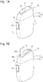
- Fig. 1A is a perspective overall view of the flavor inhaler according to the present embodiment.
- Fig. 1B is a perspective overall view of the flavor inhaler according to the embodiment which holds a flavor generating article.
- a flavor inhaler 10 according to the present embodiment is configured to generate aerosol containing a flavor, for example, by heating a flavor generating article 110 that includes a flavor source containing an aerosol source.
- the flavor inhaler 10 includes a top housing 11A, a bottom housing 11B, a cover 12, a switch 13, a lid portion 14, a first vent hole 15, and a cap 16.
- the top housing 11A and the bottom housing 11B are connected together to form an outer housing 11 located at an outermost side of the flavor inhaler 10.
- the outer housing 11 is of a size that fits in a user's hand. When using the flavor inhaler 10, the user can inhale a flavor while holding the flavor inhaler 10 in his or her hand.
- the top housing 11A includes an opening, not shown.
- the cover 12 is connected to the top housing 11A so as to close the opening.
- the cover 12 includes an opening 12a in which the flavor generating article 110 can be inserted.
- the lid portion 14 is configured to open/close the opening 12a of the cover 12.
- the lid portion 14 is mounted on the cover 12 and configured to be movable between a first position for closing the opening 12a and a second position for opening the opening 12a along a surface of the cover 12.
- the lid portion 14 thus allows or restricts access of the flavor generating article 110 to the inside of the flavor inhaler 10 (opening 61 of an insertion guide member 17 illustrated in Fig. 4 ).
- the switch 13 is used to switch between ON and OFF of actuation of the flavor inhaler 10. For example, if the user operates the switch 13 with the flavor generating article 110 inserted in the opening 12a as illustrated in Fig. 1B , electric power is supplied from a power source, not shown, to a heating member, not shown. The user thus can heat, instead of burning, the flavor generating article 110. When the flavor generating article 110 is heated, aerosol is vaporized from an aerosol source contained in the flavor generating article 110, and the flavor of the flavor source is captured in the aerosol. The user can inhale the aerosol containing the flavor by sucking a portion of the flavor generating article 110 which is protruding from the flavor inhaler 10 (portion illustrated in Fig. 1B ).
- the first vent hole 15 is a vent hole for introducing air into the inside of a heating assembly 41 (see Fig. 3 ) that is housed in an interior space of the outer housing 11.
- the cap 16 is attachable to and detachable from the bottom housing 11B.
- the cap 16 is mounted on the bottom housing 11B, to thereby form the first vent hole 15 between the bottom housing 11B and the cap 16.
- the cap 16 may include, for example, a through-hole, a notch or the like, not shown.
- a longitudinal direction of the flavor inhaler 10 refers to a direction the flavor generating article 110 is inserted into the opening 12a.
- a side into which air enters is an upstream side
- a side from which air exits is a downstream side.
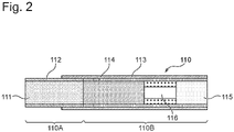
- Fig. 2 is a cross-section of the flavor generating article 110.
- the flavor generating article 110 comprises a base material portion 110A that includes a filler 111 and a first paper wrapper 112 for wrapping the filler 111, and a mouthpiece portion 110B that forms an end portion on an opposite side to the base material portion 110A.
- the base material portion 110A and the mouthpiece portion 110B are connected together by a second paper wrapper 113 that is another paper wrapper than the first paper wrapper 112.
- the second paper wrapper 113 may be omitted, and the first paper wrapper 112 may be used to connect the base material portion 110A and the mouthpiece portion 110B.
- the mouthpiece portion 110B illustrated in Fig. 2 includes a paper tube portion 114, a filter portion 115, and a hollow segment portion 116 disposed between the paper tube portion 114 and the filter portion 115.
- the hollow segment portion 116 comprises, for example, a filling layer including one or more hollow channels, and a plug wrapper that covers the filling layer.
- the filling layer has a high fiber packing density. During inhalation, therefore, air and aerosol flow only through the hollow channel or hollow channels and hardly flow through the filling layer.
- the mouthpiece portion 110B illustrated in Fig. 2 comprises three segments. According to the present embodiment, however, the mouthpiece portion 110B may comprise one or two segments or may comprise four or more segments. It is also possible, for example, to omit the hollow segment portion 116 and arrange the paper tube portion 114 and the filter portion 115 adjacent to each other to form the mouthpiece portion 110B.
- the flavor generating article 110 has a longitudinal length ranging preferably from 40 mm to 90 mm, more preferably from 50 mm to 75 mm, and still more preferably from 50 mm to 60 mm.
- the flavor generating article 110 has a circumference ranging preferably from 15 mm to 25 mm, more preferably from 17 mm to 24 mm, and still more preferably from 20 mm to 23 mm.
- the base material portion 110A of the flavor generating article 110 may have a length of 20 mm.
- the first paper wrapper 112 may have a length of 20 mm.
- the hollow segment portion 116 may have a length of 8 mm.
- the filter portion 115 may have a length of 7 mm. The length of each of the foregoing segments may be changed as necessary according to manufacturability, required quality, and the like.
- the filler 111 of the flavor generating article 110 may contain the aerosol source that is heated at predetermined temperature and generates aerosol.
- the aerosol source may be of any kind. Materials extracted from various natural products and/or components thereof may be selected according to the intended use.
- the aerosol source may be, for example, glycerin, propylene glycol, triacetin, 1, 3-butanediol or a mixture of these substances.
- An amount of the aerosol source contained in the filler 111 is not particularly limited. However, from a perspective of sufficient aerosol generation and addition of a favorable smoking flavor, the contained amount of the aerosol source is generally 5% by weight or more and preferably 10% by weight or more, and generally 50% by weight or less and preferably 20% by weight or less.
- the filler 111 of the flavor generating article 110 may contain shred tobacco as a flavor source.
- the shred tobacco may be made of any material including publicly-known materials, such as laminae and stems. If the flavor generating article 110 has a circumference of 22 mm and a length of 20 mm, the amount of the filler 111 contained in the flavor generating article 110 ranges, for example, from 200 mg to 400 mg and preferably from 250 mg to 320 mg.
- a moisture content of the filler 111 ranges, for example, from 8% by weight to 18% by weight and preferably from 10% by weight to 16% by weight.
- the moisture content in the above ranges suppresses the adhesion of a stain on the paper wrappers and improves a winding efficiency during manufacture of the base material portion 110A.
- size or preparation method for the shred tobacco used as the filler 111 may be prepared using dried tobacco leaves that are cut into pieces each having a width ranging from 0.8 mm to 1.2 mm.
- the dried tobacco leaves also may be pulverized into particles with an average particle diameter ranging from about 20 ⁇ m to about 200 ⁇ m to be equalized in size, processed into a sheet, and then shredded into pieces each having a width ranging from 0.8 mm to 1.2 mm.
- the dried tobacco leaves subjected to the above-described sheet processing may be gathered together, instead of being shredded, and used as the filler 111.
- the filler 111 may include one or more kinds of aroma chemicals.
- the aroma chemical may be of any kind but is preferably menthol from a perspective of addition of a favorable smoking flavor.
- the first and second paper wrappers 112 and 113 of the flavor generating article 110 may be made of base paper having a basis weight ranging, for example, from 20 gsm to 65 gsm, and preferably from 25 gsm to 45 gsm.
- the first paper wrapper 112 and the second paper wrapper 113 are not particularly limited in thickness. From a perspective of rigidity, air permeability, and adjustability during paper manufacturing, however, the thickness ranges from 10 ⁇ m to 100 ⁇ m, preferably from 20 ⁇ m to 75 ⁇ m, and more preferably from 30 ⁇ m to 50 ⁇ m.
- the first and second paper wrappers 112 and 113 of the flavor generating article 110 may contain a loading material.
- a contained amount of the loading material may range from 10% by weight to 60% by weight relative to total weight of the first and second paper wrappers 112 and 113, and preferably ranges from 15% by weight to 45% by weight.
- the loading material preferably ranges from 15% by weight to 45% by weight relative to the preferable range of basis weight (from 25 gsm to 45 gsm).
- the loading material may be, for example, calcium carbonate, titanium dioxide, kaolin or the like.
- the paper containing such a loading material shows a bright white color that is preferable in view of appearance of the paper used as paper wrapper for the flavor generating article 110, and can permanently maintain whiteness.
- the paper wrapper containing a large amount of such a loading material has, for example, an ISO brightness of 83% or more.
- the first and second paper wrappers 112 and 113 preferably have a tensile strength of 8 N/15 mm or higher.
- the tensile strength can be increased by reducing the contained amount of the loading material.
- the tensile strength can be increased by reducing the contained amount of the loading material to be lower than an upper limit of the contained amount of the loading material within each of the base weight ranges as exemplified above.
- Fig. 3 is a cross-section taken along and viewed in a direction of an arrow 3-3 line in Fig. 1A .
- the flavor inhaler 10 includes a power source portion 20, a circuit portion 30, and a heating portion 40 in an interior space of the outer housing 11 and of the inner housing 18.
- the top housing 11A and the bottom housing 11B which form the outer housing 11 enclose the inner housing 18 and thus house the inner housing 18 in interior spaces thereof.
- the circuit portion 30 includes a first circuit board 31, a second circuit board 32, and a third circuit board 33 which are electrically connected to one another.
- the first circuit board 31 is disposed, for example, adjacent to one surface of a rectangular power source 21 and extends in the longitudinal direction as illustrated in the drawing.
- a partition wall 34 which sections off at least a part of a region in which the power source portion 20 and the first circuit board 31 are housed.
- the partition wall 34 may be provided with a notch, a through-hole or the like for allowing fluid communication between a space on the power source portion 20 side and a space on the heating portion 40 side.
- the second circuit board 32 is disposed between the cover 12 and the power source portion 20 on an inner side of the top housing 11A and extends in a direction orthogonal to a direction the first circuit board 31 extends.
- the switch 13 is disposed adjacent to the second circuit board 32. When pushed down by the user, the switch 13 partially contacts the second circuit board 32.
- the third circuit board 33 is disposed to extend in the longitudinal direction in a space formed on an opposite side of the heating portion 40 from the opening 12a.
- the third circuit board 33 includes a main surface on which various kinds of electronic components are mounted.
- the third circuit board 33 may be disposed within the bottom housing 11B so that the main surface is inclined with respect to the longitudinal direction. This makes it possible to enlarge the main surface of the third circuit board 33, thereby making effective use of a space in the bottom housing 11B.
- the first circuit board 31, the second circuit board 32, and the third circuit board 33 each include, for example, a microprocessor and the like and are capable of controlling power supply from the power source portion 20 to the heating portion 40. This enables the first circuit board 31, the second circuit board 32, and the third circuit board 33 to control the heating of the flavor generating article 110 which is performed by the heating portion 40.
- the power source portion 20 includes the power source 21 that is electrically connected to the first circuit board 31, the second circuit board 32, and the third circuit board 33.
- the power source 21 may be, for example, a rechargeable or non-rechargeable battery.
- the power source 21 is electrically connected to the heating portion 40 through at least one of the first circuit board 31, the second circuit board 32, and the third circuit board 33.
- the power source 21 is thus capable of supplying electric power to the heating portion 40 so that the heating portion 40 may properly heat the flavor generating article 110.
- the power source 21 is disposed in parallel with the heating portion 40. If the power source 21 is increased in size, therefore, the flavor inhaler 10 does not have to be increased in longitudinal length.
- the flavor inhaler 10 includes a terminal 22 that is connectable to an external power source.
- the terminal 22 can be connected, for example, to a cable of a micro USB or the like. If the power source 21 is a rechargeable battery, current can be imparted from the external power source to the power source 21 to recharge the power source 21 by connecting the terminal 22 with an external power source.
- a data transmission cable of a micro USB or the like may be connected to the terminal 22 so that data relevant to the actuation of the flavor inhaler 10 may be transmitted to an external device.
- the heating portion 40 includes the heating assembly 41 extending in the longitudinal direction, a bottom cap 50 having a substantially L-shaped section, and the insertion guide member 17 having a substantially cylindrical shape, as illustrated in the drawing.
- the heating assembly 41 includes a plurality of cylindrical members and is formed into a cylindrical body as a whole.
- the heating assembly 41 is configured to be able to house a part of the flavor generating article 110 in the inside thereof.
- the heating assembly 41 functions to define a channel of air to be supplied to the flavor generating article 110 and also functions to heat the flavor generating article 110 from an outer periphery of the flavor generating article 110.
- the first vent hole 15 and a second vent hole 19 for introducing air into the heating assembly 41 are formed in the bottom housing 11B.
- the first vent hole 15 is in a fluid communication with an upstream end of a channel extending through the bottom cap 50 to the heating assembly 41.
- the first vent hole 15 comes into a fluid communication with an upstream end of the heating assembly 41 through a through-channel of the bottom cap 50.
- the second vent hole 19 is in a fluid communication with an upstream end of an air channel 19A formed between the outer housing 11 and the inner housing 18.
- the air channel 19A has a downstream end that is in a fluid communication with the upstream end of the channel extending through the bottom cap 50, so that the second vent hole 19, like the first vent hole 15, eventually comes into a fluid communication with the heating assembly 41.
- the heating assembly 41 has a downstream end that is in a fluid communication with an upstream end of a channel extending through the insertion guide member 17 to the opening 12a illustrated in Fig. 1B .
- the insertion guide member 17 is made, for example, of resin material.
- the insertion guide member 17 is a member placed between the cover 12 with the opening 12a and the downstream end of the heating assembly 41.
- the flavor generating article 110 is inserted from the opening 12a of the cover 12 into the flavor inhaler 10 as illustrated in Fig. 1B and passes through the insertion guide member 17. A part of the flavor generating article 110 is then disposed inside the heating assembly 41.
- the insertion guide member 17 is therefore preferably formed so that an opening on the cover 12 side is larger than an opening on the downstream side of the heating assembly 41. This facilitates the insertion of the flavor generating article 110 from the opening 12a into the insertion guide member 17.
- a side of the heating assembly 41 which is close to the first vent hole 15 and the second vent hole 19 (side close to the bottom cap 50) is an upstream side
- a side of the heating assembly 41 which is close to the opening 12a (side close to the insertion guide member 17) is a downstream side.
- Fig. 4 is a cross-section of the heating portion 40.
- the heating portion 40 includes the heating assembly 41, the bottom cap 50, and the insertion guide member 17.
- the heating assembly 41 includes a cup-like container 42 forming a chamber that houses the flavor generating article 110, a heating member 43, a heat-shrinkable tube 44, and a heat insulating member 45.
- the container 42 is provided at one end with a first opening 42a in which the flavor generating article 110 can be inserted and at the other end with a second opening 42b forming an air inlet, so that the container 42 is capable of housing the flavor generating article 110.
- the container 42 includes an inner wall configured to contact at least a part of an outer wall of the flavor generating article 110 inserted from the first opening 42a.
- the container 42 further includes a bottom wall 42d against which a tip end of the flavor generating article 110 inserted from the first opening 42a hits.
- the second opening 42b is a through-hole that is formed in the bottom wall 42d of the container 42.
- the second opening 42b is located on an upstream side of an air flow, and the first opening 42a is located on a downstream side of the air flow.
- a boss 42c is configured to press the outer wall of the inserted flavor generating article 110 radially inward.
- the heating member 43 may be a flexible film heater that comprises, for example, a heating resistor sandwiched between two films made of PI (polyimide) or the like.
- the heating member 43 is so disposed as to contact the container 42.
- the heating member 43 is disposed in an outer peripheral surface of the container 42, and an interior surface of the heating member 43 is in tight contact with an exterior surface of the container 42. Disposed along the outer peripheral surface of the container 42, the heating member 43 is deformed into a substantially cylindrical shape as a whole.
- the heat-shrinkable tube 44 has a cylindrical shape and keeps the heating member 43 in tight contact with the container 42.
- the heat-shrinkable tube 44 is thermally shrunk by being applied with heat in a position disposed on an outer peripheral side of the heating member 43.
- the heat-shrinkable tube 44 thus applies pressure to the heating member 43 so as to press the heating member 43 against the container 42.
- the heat-shrinkable tube 44 is thermally shrunk while covering a part of a downstream side of the bottom cap 50, bringing the container 42 and the bottom cap 50 into tight contact.
- the heat insulating member 45 is a cylindrical member having a double-tube structure.
- the heat insulating member 45 is disposed at predetermined distance from the heat-shrinkable tube 44 in a radially outward direction.
- the heat insulating member 45 includes an inner tubular member 45a, an outer tubular member 45b, a first ring-like member 45c, and a second ring-like member 45d.
- the inner tubular member 45a and the outer tubular member 45b are disposed side by side in a radial direction of the inserted flavor generating article 110.
- the first ring-like member 45c is disposed on a downstream side of the inner tubular member 45a and the outer tubular member 45b
- the second ring-like member 45d is disposed on an upstream side of the inner tubular member 45a and the outer tubular member 45b
- the heat insulating member 45 may be a vacuum heat insulating material having depressurized air or vacuum inside the double tube structure.
- the heat generated by the heating member 43 becomes less transmittable to the outside of the heating assembly 41 by depressurizing a space formed by the inner tubular member 45a, the outer tubular member 45b, the first ring-like member 45c, and the second ring-like member 45d.
- the heat insulating member 45 does not necessarily have to be configured as described above, and the heat insulating member 45 in the drawing may be omitted.
- the bottom cap 50 is a member forming a pipe that includes a downstream end 50a engaged with an upstream end of the container 42 (end portion on the second opening 42b side) and an upstream end 50b located on an opposite side to the downstream end 50a.
- the bottom cap 50 forms an inner channel that introduces air toward the second opening 42b of the container 42.
- the bottom cap 50 illustrated in Fig. 4 forms the inner channel that is bent into an L-like shape.
- the upstream end 50b of the bottom cap 50 is disposed close or adjacent to the first vent hole 15 and the air channel 19A which are illustrated in Fig. 3 .
- the insertion guide member 17 includes an upstream end (end portion on the first opening 42a side) that encloses an outer periphery of a downstream end of the container 42. There is a predetermined gap between the insertion guide member 17 and the container 42.
- the upstream end of the insertion guide member 17 has an inner diameter that is larger than an outer diameter of the downstream end of the container 42 and is therefore capable of enclosing the downstream end of the container 42.
- Fig. 5 is a cross-section of the insertion guide member 17.
- Fig. 6 is a perspective view of the insertion guide member 17.
- Figs. 7 and 8 are perspective cross-sections of the insertion guide member 17.
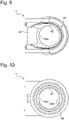
- Fig. 9 is a plan view of the insertion guide member.
- Fig. 10 is a bottom view of the insertion guide member.
- the insertion guide member 17 includes the opening 61, an inner peripheral surface 62, a protruding portion 63, a guide portion 64, a groove portion 65, and an enclosing portion 66.
- the opening 61 is in communication with the opening 12a of the cover 12 and so configured that the flavor generating article 110 can be inserted therein.
- the inner peripheral surface 62 encloses the outer periphery of the flavor generating article 110 inserted from the opening 61.
- the inner peripheral surface 62 includes non-protruding portions 62a that are formed adjacent to each other on the opening 61 side of the protruding portion 63 and on an opposite side from the opening 61.
- the non-protruding portions 62a include regions located away from an outer peripheral surface of the inserted flavor generating article 110.
- the protruding portion 63 has a ring-like shape and protrudes from the inner peripheral surface 62 to extend over an entire circumference of the inner peripheral surface 62.
- the protruding portion 63 is configured to abut on the flavor generating article 110 over an entire circumference of the outer peripheral surface of the inserted flavor generating article 110.
- the protruding portion 63 includes, in a circumferential direction of the inner peripheral surface 62, a portion that changes in a position in the longitudinal direction of the flavor generating article 110 that abuts on the inserted flavor generating article 110.
- the protruding portion 63 includes an inclined portion 63a, two convex portions 63b, and a pair of horizontal portions 63c.
- the inclined portion 63a extends at an angle to a longitudinal direction of the inserted flavor generating article 110.
- the convex portions 63b are provided at two places so as to protrude toward the opening 61.
- the two convex portions 63b are evenly spaced in the circumferential direction of the inner peripheral surface 62.
- the horizontal portions 63c extend perpendicularly to the longitudinal direction of the inserted flavor generating article 110 and face each other across a center axis of the inserted flavor generating article 110.
- the horizontal portions 63c form end portions of the protruding portion 63 on an opposite side from the opening 61 in the longitudinal direction of the inserted flavor generating article 110 (lower side on Fig. 5 ).
- the guide portion (second guide portion) 64 is provided in the inner peripheral surface 62 and extends from the horizontal portion 63c to an opposite side from the opening 61 (lower side on Fig. 5 ) along the longitudinal direction of the inserted flavor generating article 110.
- the guide portion 64 guides movement of the flavor generating article 110 relative to the inner peripheral surface 62.
- the guide portion 64 includes a guide surface 64a that is disposed to face the outer peripheral surface of the inserted flavor generating article 110.
- the guide surface 64a is located away from the outer peripheral surface of the inserted flavor generating article 110 and extends along the longitudinal direction of the inserted flavor generating article 110.
- the groove portion 65 is provided on the opening 61 side of the insertion guide member 17.
- the groove portion 65 forms a space that allows the lid portion 14 to move.
- the lid portion 14 is mounted on the cover 12 and opens/closes the opening 12a of the cover 12.
- the enclosing portion 66 is provided in the insertion guide member 17 to be located on the opposite side from the opening 61 (upstream end of the insertion guide member 17).
- the enclosing portion 66 encloses the outer periphery of the downstream end of the container 42.
- a region where the outer peripheral surface of the flavor generating article 110 is away from the inner peripheral surface 62, that is, a gap is formed at each of longitudinally located positions in the flavor generating article 110 in a region where the outer peripheral surface of the inserted flavor generating article 110 abuts on the protruding portion 63. Therefore, if the outer peripheral surface of the flavor generating article 110 receives pressure from the protruding portion 63 during the insertion and/or removal of the flavor generating article 110, at least part of the pressure is used for movement and/or deformation of the flavor generating article 110 in the gaps.
- a perpendicular reaction force that is actually applied to the outer peripheral surface of the flavor generating article 110 from the protruding portion 63 is smaller than the pressure in a case where the gaps are not formed. According to the above-described configuration, the perpendicular reaction force is small, which is applied to the outer peripheral surface of the flavor generating article 110 from the protruding portion 63. This reduces a frictional force acting on the flavor generating article 110 during the insertion and/or removal of the flavor generating article 110.
- the protruding portion 63 abuts on the flavor generating article 110 over the entire circumference of the outer peripheral surface of the inserted flavor generating article 110, which prevents thermal vapor generated in the heating portion 40 from leaking through the opening 61.
- the protruding portion 63 may be configured to abut on a part of each of longitudinally located portions of the inserted flavor generating article 110, which is easy to be elastically deformed by receiving a radially inward pressure.
- the protruding portion 63 may be configured to abut on the paper tube portion 114 in the flavor generating article 110 illustrated in Fig. 2 .
- the guide portion 64 includes the guide surface 64a disposed to face the outer peripheral surface of the inserted flavor generating article 110, the guide surface 64a prevents the inserted flavor generating article 110 from oscillating about the horizontal portion 63c serving as a fulcrum.
- the insertion guide member 17 may be formed by combining a plurality of members. This makes it easy to form the insertion guide member 17 having a complicated shape.
- the protruding portion 63 may be formed at a joint between the plurality of members. If the plurality of members are combined, it is necessary to eliminate a step created at the joint between the plurality of members. However, if the step is used as the protruding portion 63, the process of eliminating the step can be omitted.
- the non-protruding portion 62a may be formed only either on the opening 61 side of the protruding portion 63 or on the opposite side from the opening 61.
- the convex portions 63b do not necessarily have to be provided in two places and may be provided in three or more places as long as the convex portions 63b are disposed at regular intervals in the circumferential direction of the inner peripheral surface 62.
- the inner peripheral surface 62 may be provided with only one convex portion 63b.
- the guide portion (first guide portion) 64 may extend from the horizontal portion 63c toward the opening 61 (upper side on Fig. 5 ) along the longitudinal direction of the inserted flavor generating article 110.
- the guide portion 64 may extend only from either one of the horizontal portions 63c.
- Fig. 11 is a perspective view of a protruding portion according to Modification Example 1.
- Fig. 12 is a cross-section schematically showing an inner peripheral surface according to Modification Example 1.
- Fig. 13 is a cross-section schematically showing the inner peripheral surface according to Modification Example 1.
- Fig. 12 is a cross-section of an inner peripheral surface 62 taken along and viewed in a direction of an arrow 12-12 shown in Fig. 11.
- Fig. 13 is a cross-section of the inner peripheral surface 62 taken along and viewed in a direction of an arrow 13-13 shown in Fig. 11 .
- the protruding portion 63 is formed of an inclined portion 63a extending at an angle to a longitudinal direction of an inserted flavor generating article 110. According to the above-described configuration, a perpendicular reaction force that is applied to an outer peripheral surface of the flavor generating article 110 from the protruding portion 63 can be evenly dispersed in the longitudinal direction of the flavor generating article 110. There is one or two contact points between the protruding portion 63 and the flavor generating article 110 at each of longitudinally located positions in the flavor generating article 110 in a region where the outer peripheral surface of the inserted flavor generating article 110 abuts on the protruding portion 63. This enlarges a gap at each of the longitudinally located positions in the flavor generating article 110 and thus facilitates movement and/or deformation of the flavor generating article 110.
- Fig. 14 is a perspective view of a protruding portion according to Modification Example 2.
- Fig. 15 is a cross-section schematically showing an inner peripheral surface according to Modification Example 2.
- Fig. 16 is a cross-section schematically showing the inner peripheral surface according to Modification Example 2.
- Fig. 15 is a cross-section of an inner peripheral surface 62 taken along and viewed in a direction of an arrow 15-15 shown in Fig. 14.
- Fig. 16 is a cross-section of the inner peripheral surface 62 taken along and viewed in a direction of an arrow 16-16 shown in Fig. 14 .
- a protruding portion 63 is formed of an inclined portion 63a as in Modification Example 1.
- a guide portion (second guide portion) 64 extends from an opening 61-side (upper side on Fig. 14 ) end portion of the protruding portion 63 to an opposite side from the opening 61 (lower side on Fig. 14 ) along a longitudinal direction of an inserted flavor generating article 110.
- the guide portion 64 includes a guide surface 64a disposed to face an outer peripheral surface of the inserted flavor generating article 110.
- the guide surface 64a prevents oscillation of the inserted flavor generating article 110. Since the guide portion 64 extends from the opening 61-side (upper side on Fig. 14 ) end portion of the of the protruding portion 63 to the opposite side from the opening 61 (lower side on Fig. 14 ), the guide portion 64 is capable of guiding movement of the flavor generating article 110 to a large extent in the longitudinal direction of the flavor generating article 110.
- the guide portion 64 does not necessarily have to extend from the opening 61-side (upper side on Fig. 14 ) end portion of the protruding portion 63 and may extend from anywhere in the protruding portion 63.
- the guide portion (first guide portion) 64 may extend from the protruding portion 63 toward the opening 61 (upper side on Fig. 14 ) along the longitudinal direction of the inserted flavor generating article 110.
- Fig. 17 is a perspective view of a protruding portion according to Modification Example 3.
- Fig. 18 is a cross-section schematically showing an inner peripheral surface according to Modification Example 3.
- Fig. 19 is a cross-section schematically showing the inner peripheral surface according to Modification Example 3.
- Fig. 18 is a cross-section of an inner peripheral surface 62 taken along and viewed in a direction of an arrow 18-18 shown in Fig. 17.
- Fig. 19 is a cross-section of the inner peripheral surface 62 taken along and viewed in a direction of an arrow 19-19 shown in Fig. 17 .
- a protruding portion 63 includes an inclined portion 63a, two perpendicular portions 63d, and a horizontal portion 63c.
- the perpendicular portions 63d extend side by side along a longitudinal direction of an inserted flavor generating article 110.
- the horizontal portion (first horizontal portion) 63c extends perpendicularly to the longitudinal direction of the inserted flavor generating article 110 and forms an opening 61-side (upper side on Fig. 17 ) end portion of the protruding portion 63 in the longitudinal direction of the inserted flavor generating article 110.
- the perpendicular portions 63d extend from opening 61-side (upper side on Fig. 17 ) end portions of the inclined portion 63a toward the opening 61, and opening 61-side end portions of the perpendicular portions 63d are connected together via the horizontal portion 63c.
- the perpendicular portions 63d function as insertion guides for guiding movement of the flavor generating article 110 relative to the inner peripheral surface 62, which eliminates the necessity of the guide portion 64 illustrated, for example, in Fig. 14 and other drawings.
- the horizontal portion 63c functions as a bearing for positioning the inserted flavor generating article 110 in a radial direction.
- Fig. 20 is a perspective view of a protruding portion according to Modification Example 4.
- Fig. 21 is a cross-section schematically showing an inner peripheral surface according to Modification Example 4.
- Fig. 22 is a cross-section schematically showing the inner peripheral surface according to Modification Example 4.
- Fig. 21 is a cross-section of an inner peripheral surface 62 taken along and viewed in a direction of an arrow 21-21 shown in Fig. 20.
- Fig. 22 is a cross-section of the inner peripheral surface 62 taken along and viewed in a direction of an arrow 22-22 shown in Fig. 20 .
- the protruding portion 63 includes an inclined portion 63a, a pair of perpendicular portions 63d, and a horizontal portion 63c.
- the perpendicular portions 63d extend along a longitudinal direction of an inserted flavor generating article 110.
- the horizontal portion (first horizontal portion) 63c extends perpendicularly to the longitudinal direction of the inserted flavor generating article 110 to form an opening 61-side (upper side on Fig. 20 ) end portion of the protruding portion 63 in the longitudinal direction of the inserted flavor generating article 110.
- the perpendicular portions 63d are disposed to face each other across a center axis of the inserted flavor generating article 110 at a substantially middle position in a longitudinal direction of the inclined portion 63a.
- the horizontal portion 63c does not necessarily have to be provided.
- the perpendicular portions 63d function as insertion guides for guiding movement of the flavor generating article 110 relative to the inner peripheral surface 62, which eliminates the necessity of the guide portion 64 illustrated, for example, in Fig. 14 or other drawings.
- the horizontal portion 63c functions as a bearing for positioning the inserted flavor generating article 110 in a radial direction. Since the perpendicular portions 63d are disposed at the longitudinally middle position of the inclined portion 63a, end portions of the perpendicular portions 63d are prevented from getting caught on the flavor generating article 110 during insertion and/or removal of the flavor generating article 110.
- Fig. 23 is a perspective view of a protruding portion according to Modification Example 5.
- Fig. 24 is a cross-section schematically showing an inner peripheral surface according to Modification Example 5.
- Fig. 25 is a cross-section schematically showing the inner peripheral surface according to Modification Example 5.
- Fig. 24 is a cross-section of an inner peripheral surface 62 taken along and viewed in a direction of an arrow 24-24 shown in Fig. 23.
- Fig. 25 is a cross-section of the inner peripheral surface 62 taken along and viewed in a direction of an arrow 25-25 shown in Fig. 23 .
- the protruding portion 63 includes four perpendicular portions 63d and four horizontal portions 63c.
- the perpendicular portions 63d extend along a longitudinal direction of an inserted flavor generating article 110.
- the horizontal portion 63c extends perpendicularly to the longitudinal direction of the inserted flavor generating article 110 and connect every two adjacent end portions of the perpendicular portions 63d to one another.
- the horizontal portions (first horizontal portion, second horizontal portion) 63c form opening 61-side (upper side on Fig. 23 ) end portions of the protruding portion 63 in the longitudinal direction of the inserted flavor generating article 110 and further form end portions on an opposite side from the opening 61 (lower side on Fig. 23 ).
- the perpendicular portions 63d and the horizontal portion 63c form two convex portions 63b protruding toward the opening 61 (upper side on Fig. 23 ).
- the two convex portions (upwardly convex portions) 63b are disposed at regular intervals in a circumferential direction of the inner peripheral surface 62. Viewed from the horizontal portion 63c formed in an opening 61-side end portion of the protruding portion 63, it can be also said that the perpendicular portions 63d and the horizontal portion 63c form two convex portions (downwardly convex portions) protruding toward an opposite side from the opening 61 (lower side on Fig. 23 ).
- the perpendicular portions 63d function as insertion guides for guiding movement of the inserted flavor generating article 110 relative to the inner peripheral surface 62, which eliminates the necessity of the guide portion 64 illustrated, for example, in Fig. 14 and other drawings.
- the horizontal portion 63c functions as a bearing for positioning the inserted flavor generating article 110 in a radial direction. It is also possible to increase the entire length of the protruding portion 63, so that the function of the insertion guides can be effectively exerted.
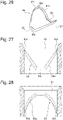
- Fig. 26 is a perspective view of a protruding portion according to Modification Example 6.
- Fig. 27 is a cross-section schematically showing an inner peripheral surface according to Modification Example 6.
- Fig. 28 is a cross-section schematically showing the inner peripheral surface according to Modification Example 6.
- Fig. 27 is a cross-section of an inner peripheral surface 62 taken along and viewed in a direction of an arrow 27-27 shown in Fig. 26.
- Fig. 28 is a cross-section of the inner peripheral surface 62 taken along and viewed in a direction of an arrow 28-28 shown in Fig. 26 .
- the protruding portion 63 includes an inclined portion 63a, two convex portions 63b, and four horizontal portions 63c.
- the convex portions 63b are provided in two places so as to protrude toward an opening 61 (upper side on Fig. 26 ).
- the two convex portions 63b are disposed at regular intervals in a circumferential direction of the inner peripheral surface 62.
- the horizontal portions 63c extend perpendicularly to a longitudinal direction of an inserted flavor generating article 110.
- the horizontal portions (first horizontal portion, second horizontal portion) 63c form opening 61-side (upper side on Fig.
- the horizontal portions 63c are configured as short in length as possible.
- the horizontal portions 63c are configured as short in length as possible, insertion friction that is caused during insertion and/or removal of the flavor generating article 110 can be reduced, and yet at the same time, the horizontal portions 63c still function as bearings for positioning the inserted flavor generating article 110 in a radial direction.
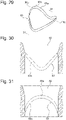
- Fig. 29 is a perspective view of a protruding portion according to Modification Example 7.
- Fig. 30 is a cross-section schematically showing an inner peripheral surface according to Modification Example 7.
- Fig. 31 is a cross-section schematically showing the inner peripheral surface according to Modification Example 7.
- Fig.30 is a cross-section of an inner peripheral surface 62 taken along and viewed in a direction of an arrow 30-30 shown in Fig. 29.
- Fig. 31 is a cross-section of the inner peripheral surface 62 taken along and viewed in a direction of an arrow 31-31 shown in Fig. 29 .
- a protruding portion 63 includes an inclined portion 63a and two convex portions 63b.
- the convex portions 63b are provided in two places so as to protrude toward an opening 61 (upper side on Fig. 29 ).
- the two convex portions 63b are disposed at regular intervals in a circumferential direction of the inner peripheral surface 62.
- a perpendicular portion extending along a longitudinal direction of an inserted flavor generating article 110 and a horizontal portion extending perpendicularly to the longitudinal direction of the inserted flavor generating article 110 are omitted. This prevents the flavor generating article 110 from getting stuck during insertion and/or removal of the flavor generating article 110.
- a first mode provides a flavor inhaler used with a rod-like flavor generating article.
- the flavor inhaler comprises an insertion guide member including an opening in which the flavor generating article can be inserted, an inner peripheral surface enclosing an outer periphery of the flavor generating article inserted from the opening, and a ring-like protruding portion that protrudes from the inner peripheral surface to extend over an entire circumference of the inner peripheral surface and abuts on the flavor generating article over the entire circumference of an outer peripheral surface of the inserted flavor generating article.
- the protruding portion includes, in a circumferential direction of the inner peripheral surface, a portion that changes in a position in the longitudinal direction of the flavor generating article that abuts on the outer peripheral surface of the inserted flavor generating article.
- the inner peripheral surface includes a non-protruding portion that is formed adjacent to at least either one of the opening side of the protruding portion and an opposite side from the opening and includes a region located away from the outer peripheral surface of the inserted flavor generating article.
- the protruding portion includes an inclined portion extending at an angle to a longitudinal direction of the inserted flavor generating article.
- the protruding portion includes a plurality of convex portions protruding toward the opening, and the plurality of convex portions are disposed at regular intervals in the circumferential direction of the inner peripheral surface.
- the protruding portion includes at least one horizontal portion extending perpendicularly to the longitudinal direction of the inserted generating article.
- the at least one horizontal portion includes a first horizontal portion that forms an opening-side end portion of the protruding portion in the longitudinal direction and/or a second horizontal portion that forms an end portion on an opposite side from the opening.
- the protruding portion includes a pair of horizontal portions extending perpendicularly to the longitudinal direction of the inserted flavor generating article and facing each other across a center axis of the inserted flavor generating article.
- the pair of horizontal portions forms end portions of the protruding portion on the opposite side from the opening in the longitudinal direction.
- the flavor inhaler includes at least one guide portion provided to the inner peripheral surface and configured to guide movement of the flavor generating article relative to the inner peripheral surface.
- the at least one guide portion includes a first guide portion extending from the protruding portion toward the opening along the longitudinal direction of the inserted flavor generating article and/or a second guide portion extending toward the opposite side from the opening.
- the guide portion includes a guide surface disposed to face the outer peripheral surface of the inserted flavor generating article.
- the guide surface is located away from the outer peripheral surface of the inserted flavor generating article and extends along the longitudinal direction.
- the protruding portion includes a pair of perpendicular portions extending side by side along the longitudinal direction of the inserted flavor generating article, and a horizontal portion extending perpendicularly to the longitudinal direction.
- the pair of perpendicular portions extends from an opening-side end portion of an inclined portion toward the opening-side, and opening-side end portions of the pair of perpendicular portions are connected together via the horizontal portion.
- the protruding portion includes a pair of perpendicular portions extending along the longitudinal direction of the inserted flavor generating article, and the pair of perpendicular portions is disposed to face each other across the longitudinal direction.
- the protruding portion includes a plurality of perpendicular portions extending along the longitudinal direction of the inserted flavor generating article, and a horizontal portion extending perpendicularly to the longitudinal direction and connecting every two adjacent end portions of the perpendicular portions.
- the perpendicular portions and the horizontal portion form an upwardly convex portion protruding toward the opening and/or a downwardly convex portion protruding toward an opposite side from the opening.
- the insertion guide member is formed by combining a plurality of members, and the protruding portion is formed at a joint between the plurality of members.
- a 14th mode provides an insertion guide member for a rod-like flavor generating article, comprising an opening in which a flavor generating article can be inserted, an inner peripheral surface enclosing an outer periphery of the flavor generating article inserted from the opening, and a ring-like protruding portion that protrudes from the inner peripheral surface to extend over an entire circumference of the inner peripheral surface and abuts on the flavor generating article over an entire circumference of the outer peripheral surface of the inserted flavor generating article.
- the protruding portion includes, in a circumferential direction of the inner peripheral surface, a portion that changes in a position in the longitudinal direction of the flavor generating article that abuts on the outer peripheral surface of the inserted flavor generating article.
Landscapes
- Cigarettes, Filters, And Manufacturing Of Filters (AREA)
- Disinfection, Sterilisation Or Deodorisation Of Air (AREA)
Applications Claiming Priority (1)
| Application Number | Priority Date | Filing Date | Title |
|---|---|---|---|
| PCT/JP2019/026175 WO2021001908A1 (fr) | 2019-07-01 | 2019-07-01 | Inhalateur d'arôme et élément de guidage d'insertion |
Publications (2)
| Publication Number | Publication Date |
|---|---|
| EP3995013A1 true EP3995013A1 (fr) | 2022-05-11 |
| EP3995013A4 EP3995013A4 (fr) | 2023-05-31 |
Family
ID=74100969
Family Applications (1)
| Application Number | Title | Priority Date | Filing Date |
|---|---|---|---|
| EP19936045.4A Pending EP3995013A4 (fr) | 2019-07-01 | 2019-07-01 | Inhalateur d'arôme et élément de guidage d'insertion |
Country Status (4)
| Country | Link |
|---|---|
| EP (1) | EP3995013A4 (fr) |
| JP (2) | JP7245331B2 (fr) |
| TW (1) | TW202102144A (fr) |
| WO (1) | WO2021001908A1 (fr) |
Family Cites Families (10)
| Publication number | Priority date | Publication date | Assignee | Title |
|---|---|---|---|---|
| US5388594A (en) * | 1991-03-11 | 1995-02-14 | Philip Morris Incorporated | Electrical smoking system for delivering flavors and method for making same |
| US5954979A (en) | 1997-10-16 | 1999-09-21 | Philip Morris Incorporated | Heater fixture of an electrical smoking system |
| GB2534213B (en) * | 2015-01-19 | 2018-02-21 | Ngip Res Ltd | Aerosol-generating device |
| TW201742556A (zh) * | 2016-05-13 | 2017-12-16 | British American Tobacco Investments Ltd | 用以加熱可吸菸材料之裝置(一) |
| US10881139B2 (en) * | 2016-07-07 | 2021-01-05 | Altria Client Services Llc | Non-combustible vaping element with tobacco insert |
| US11825881B2 (en) | 2016-09-15 | 2023-11-28 | Philip Morris Products S.A. | Aerosol-generating device providing secure retention for aerosol-generating articles |
| EP3515219B1 (fr) * | 2016-09-20 | 2022-11-16 | Nicoventures Trading Limited | Procédé de fabrication d'un appareil de fourniture d'aérosol et appareil de fourniture d'aérosol |
| CN106880086B (zh) | 2017-04-07 | 2023-07-25 | 云南中烟工业有限责任公司 | 一种电子烟与低温烤烟的混合烟 |
| WO2018190606A1 (fr) * | 2017-04-11 | 2018-10-18 | 주식회사 케이티앤지 | Dispositif de génération d'aérosol |
| GB201705888D0 (en) * | 2017-04-12 | 2017-05-24 | British American Tobacco Investments Ltd | Apparatus for volatilising smokable material and a smoking article |
-
2019
- 2019-07-01 JP JP2021529583A patent/JP7245331B2/ja active Active
- 2019-07-01 EP EP19936045.4A patent/EP3995013A4/fr active Pending
- 2019-07-01 WO PCT/JP2019/026175 patent/WO2021001908A1/fr unknown
- 2019-08-08 TW TW108128305A patent/TW202102144A/zh unknown
-
2023
- 2023-03-10 JP JP2023037158A patent/JP2023071995A/ja active Pending
Also Published As
| Publication number | Publication date |
|---|---|
| JPWO2021001908A1 (fr) | 2021-01-07 |
| EP3995013A4 (fr) | 2023-05-31 |
| JP2023071995A (ja) | 2023-05-23 |
| TW202102144A (zh) | 2021-01-16 |
| WO2021001908A1 (fr) | 2021-01-07 |
| JP7245331B2 (ja) | 2023-03-23 |
Similar Documents
| Publication | Publication Date | Title |
|---|---|---|
| CN106659248B (zh) | 用于气雾剂递送装置的具有电子器件隔室的匣体和相关组装方法 | |
| CN110494054B (zh) | 具备移动式加热器的气溶胶生成装置 | |
| CN113163865A (zh) | 具有改善的连接性、气流和气溶胶路径的气溶胶递送装置 | |
| WO2021171740A1 (fr) | Système à fumer | |
| CN109068751A (zh) | 电子烟 | |
| JPH0367577A (ja) | 喫煙品に対する添加物用容器 | |
| US20210235761A1 (en) | Housing and flavor aspirator provided with same | |
| EP3995015B1 (fr) | Ensemble chauffant et inhalateur d'arôme | |
| EP3995013A1 (fr) | Inhalateur d'arôme et élément de guidage d'insertion | |
| EP3995017A1 (fr) | Inhalateur d'arôme | |
| EP3995014A1 (fr) | Ensemble de chauffage et inhalateur d'arôme | |
| EP4094599A1 (fr) | Dispositif d'aspiration | |
| EP3995016A1 (fr) | Inhalateur d'arôme | |
| KR102306688B1 (ko) | 증발식 흡연장치용 흡연물품 | |
| EP3871533A1 (fr) | Appareil de chauffage et inhalateur d'arôme qui en est pourvu | |
| US20230309614A1 (en) | Cartomizer for an Aerosol Generating Device with Leakage Prevention | |
| US20230284692A1 (en) | Aerosol Generating Device with Lip Seal for Battery Degassing Mitigation | |
| CN212035997U (zh) | 一种口味雾化器 | |
| KR20220066103A (ko) | 에어로졸 제공 시스템들 | |
| CN110623304A (zh) | 一种口味雾化器 | |
| TW202042674A (zh) | 吸煙替代系統 | |
| KR20160002391U (ko) | 복수개의 니코틴액 카트리지가 장착될 수 있는 전자식 흡연장치 |
Legal Events
| Date | Code | Title | Description |
|---|---|---|---|
| STAA | Information on the status of an ep patent application or granted ep patent |
Free format text: STATUS: THE INTERNATIONAL PUBLICATION HAS BEEN MADE |
|
| PUAI | Public reference made under article 153(3) epc to a published international application that has entered the european phase |
Free format text: ORIGINAL CODE: 0009012 |
|
| STAA | Information on the status of an ep patent application or granted ep patent |
Free format text: STATUS: REQUEST FOR EXAMINATION WAS MADE |
|
| 17P | Request for examination filed |
Effective date: 20220128 |
|
| AK | Designated contracting states |
Kind code of ref document: A1 Designated state(s): AL AT BE BG CH CY CZ DE DK EE ES FI FR GB GR HR HU IE IS IT LI LT LU LV MC MK MT NL NO PL PT RO RS SE SI SK SM TR |
|
| DAV | Request for validation of the european patent (deleted) | ||
| DAX | Request for extension of the european patent (deleted) | ||
| REG | Reference to a national code |
Ref country code: DE Ref legal event code: R079 Free format text: PREVIOUS MAIN CLASS: A24F0047000000 Ipc: A24F0040400000 |
|
| A4 | Supplementary search report drawn up and despatched |
Effective date: 20230502 |
|
| RIC1 | Information provided on ipc code assigned before grant |
Ipc: A24F 40/46 20200101ALN20230424BHEP Ipc: A24F 40/20 20200101ALN20230424BHEP Ipc: A24F 40/40 20200101AFI20230424BHEP |