EP3995015B1 - Ensemble chauffant et inhalateur d'arôme - Google Patents
Ensemble chauffant et inhalateur d'arôme Download PDFInfo
- Publication number
- EP3995015B1 EP3995015B1 EP19936279.9A EP19936279A EP3995015B1 EP 3995015 B1 EP3995015 B1 EP 3995015B1 EP 19936279 A EP19936279 A EP 19936279A EP 3995015 B1 EP3995015 B1 EP 3995015B1
- Authority
- EP
- European Patent Office
- Prior art keywords
- heating
- heat
- region
- generating article
- flavor generating
- Prior art date
- Legal status (The legal status is an assumption and is not a legal conclusion. Google has not performed a legal analysis and makes no representation as to the accuracy of the status listed.)
- Active
Links
- 238000010438 heat treatment Methods 0.000 title claims description 171
- 239000000796 flavoring agent Substances 0.000 title claims description 150
- 235000019634 flavors Nutrition 0.000 title claims description 150
- 230000020169 heat generation Effects 0.000 claims description 32
- 230000002093 peripheral effect Effects 0.000 claims description 31
- 238000003780 insertion Methods 0.000 claims description 27
- 230000037431 insertion Effects 0.000 claims description 27
- 239000012530 fluid Substances 0.000 claims description 14
- 238000004891 communication Methods 0.000 claims description 12
- 239000000758 substrate Substances 0.000 claims description 7
- 239000000463 material Substances 0.000 description 21
- 239000000443 aerosol Substances 0.000 description 17
- 238000011144 upstream manufacturing Methods 0.000 description 16
- 239000000945 filler Substances 0.000 description 10
- 241000208125 Nicotiana Species 0.000 description 7
- 235000002637 Nicotiana tabacum Nutrition 0.000 description 7
- 229920001721 polyimide Polymers 0.000 description 5
- DNIAPMSPPWPWGF-UHFFFAOYSA-N Propylene glycol Chemical compound CC(O)CO DNIAPMSPPWPWGF-UHFFFAOYSA-N 0.000 description 3
- 230000005540 biological transmission Effects 0.000 description 3
- 239000007769 metal material Substances 0.000 description 3
- 230000000391 smoking effect Effects 0.000 description 3
- 239000000126 substance Substances 0.000 description 3
- PUPZLCDOIYMWBV-UHFFFAOYSA-N (+/-)-1,3-Butanediol Chemical compound CC(O)CCO PUPZLCDOIYMWBV-UHFFFAOYSA-N 0.000 description 2
- VTYYLEPIZMXCLO-UHFFFAOYSA-L Calcium carbonate Chemical compound [Ca+2].[O-]C([O-])=O VTYYLEPIZMXCLO-UHFFFAOYSA-L 0.000 description 2
- PEDCQBHIVMGVHV-UHFFFAOYSA-N Glycerine Chemical compound OCC(O)CO PEDCQBHIVMGVHV-UHFFFAOYSA-N 0.000 description 2
- 239000004642 Polyimide Substances 0.000 description 2
- 229910000831 Steel Inorganic materials 0.000 description 2
- GWEVSGVZZGPLCZ-UHFFFAOYSA-N Titan oxide Chemical compound O=[Ti]=O GWEVSGVZZGPLCZ-UHFFFAOYSA-N 0.000 description 2
- 235000019504 cigarettes Nutrition 0.000 description 2
- 238000004049 embossing Methods 0.000 description 2
- 230000002349 favourable effect Effects 0.000 description 2
- 238000004519 manufacturing process Methods 0.000 description 2
- 229910052751 metal Inorganic materials 0.000 description 2
- 239000002184 metal Substances 0.000 description 2
- 239000002245 particle Substances 0.000 description 2
- 238000005192 partition Methods 0.000 description 2
- 239000011347 resin Substances 0.000 description 2
- 229920005989 resin Polymers 0.000 description 2
- 239000010959 steel Substances 0.000 description 2
- URAYPUMNDPQOKB-UHFFFAOYSA-N triacetin Chemical compound CC(=O)OCC(OC(C)=O)COC(C)=O URAYPUMNDPQOKB-UHFFFAOYSA-N 0.000 description 2
- NOOLISFMXDJSKH-UTLUCORTSA-N (+)-Neomenthol Chemical group CC(C)[C@@H]1CC[C@@H](C)C[C@@H]1O NOOLISFMXDJSKH-UTLUCORTSA-N 0.000 description 1
- 239000005995 Aluminium silicate Substances 0.000 description 1
- NOOLISFMXDJSKH-UHFFFAOYSA-N DL-menthol Natural products CC(C)C1CCC(C)CC1O NOOLISFMXDJSKH-UHFFFAOYSA-N 0.000 description 1
- 241001085205 Prenanthella exigua Species 0.000 description 1
- 235000012211 aluminium silicate Nutrition 0.000 description 1
- 230000000712 assembly Effects 0.000 description 1
- 238000000429 assembly Methods 0.000 description 1
- 235000019437 butane-1,3-diol Nutrition 0.000 description 1
- 229910000019 calcium carbonate Inorganic materials 0.000 description 1
- 239000000470 constituent Substances 0.000 description 1
- 230000003247 decreasing effect Effects 0.000 description 1
- 239000000835 fiber Substances 0.000 description 1
- 238000001914 filtration Methods 0.000 description 1
- 235000011187 glycerol Nutrition 0.000 description 1
- 239000001087 glyceryl triacetate Substances 0.000 description 1
- 235000013773 glyceryl triacetate Nutrition 0.000 description 1
- 239000011810 insulating material Substances 0.000 description 1
- NLYAJNPCOHFWQQ-UHFFFAOYSA-N kaolin Chemical compound O.O.O=[Al]O[Si](=O)O[Si](=O)O[Al]=O NLYAJNPCOHFWQQ-UHFFFAOYSA-N 0.000 description 1
- 229940041616 menthol Drugs 0.000 description 1
- 239000000203 mixture Substances 0.000 description 1
- 229930014626 natural product Natural products 0.000 description 1
- 238000012856 packing Methods 0.000 description 1
- 230000035699 permeability Effects 0.000 description 1
- 238000002360 preparation method Methods 0.000 description 1
- 238000012545 processing Methods 0.000 description 1
- 235000013772 propylene glycol Nutrition 0.000 description 1
- 230000003252 repetitive effect Effects 0.000 description 1
- 229910001220 stainless steel Inorganic materials 0.000 description 1
- 239000010935 stainless steel Substances 0.000 description 1
- 239000004408 titanium dioxide Substances 0.000 description 1
- 229960002622 triacetin Drugs 0.000 description 1
- 238000004804 winding Methods 0.000 description 1
Images


Classifications
-
- A—HUMAN NECESSITIES
- A24—TOBACCO; CIGARS; CIGARETTES; SIMULATED SMOKING DEVICES; SMOKERS' REQUISITES
- A24F—SMOKERS' REQUISITES; MATCH BOXES; SIMULATED SMOKING DEVICES
- A24F40/00—Electrically operated smoking devices; Component parts thereof; Manufacture thereof; Maintenance or testing thereof; Charging means specially adapted therefor
- A24F40/40—Constructional details, e.g. connection of cartridges and battery parts
- A24F40/46—Shape or structure of electric heating means
-
- A—HUMAN NECESSITIES
- A24—TOBACCO; CIGARS; CIGARETTES; SIMULATED SMOKING DEVICES; SMOKERS' REQUISITES
- A24D—CIGARS; CIGARETTES; TOBACCO SMOKE FILTERS; MOUTHPIECES FOR CIGARS OR CIGARETTES; MANUFACTURE OF TOBACCO SMOKE FILTERS OR MOUTHPIECES
- A24D1/00—Cigars; Cigarettes
- A24D1/20—Cigarettes specially adapted for simulated smoking devices
Definitions
- the invention relates to heating assemblies and flavor inhalers.
- flavor inhalers used to inhale flavors without burning base material containing a flavor source.
- These well-known flavor inhalers include an electrical smoking system with a heating element that slidingly receives a cigarette inserted into a cigarette receiver (see Patent Literature 1, for example).
- An object of the invention is to provide a heating assembly and a flavor inhaler which have novel structures.
- the heating assembly according to the invention is set out in claim 1.
- Another embodiment of the invention provides a flavor inhaler comprising the above-described heating assembly.
- Fig. 1A is a perspective overall view of a flavor inhaler according to one embodiment.
- Fig. 1B is a perspective overall view of the flavor inhaler according to the one embodiment which holds a flavor generating article.
- a flavor inhaler 10 according to the present embodiment is configured to generate aerosol containing a flavor, for example, by heating a flavor generating article 110 including a flavor source containing an aerosol source.
- the flavor inhaler 10 includes a top housing 11A, a bottom housing 11B, a cover 12, a switch 13, a lid portion 14, a first vent hole 15, and a cap 16.
- the top housing 11A and the bottom housing 11B are connected together to form an outer housing 11 located at an outermost side of the flavor inhaler 10.
- the outer housing 11 is of a size that fits in a user's hand. When using the flavor inhaler 10, the user can inhale a flavor while holding the flavor inhaler 10 in his or her hand.
- the top housing 11A includes an opening, not shown.
- the cover 12 is connected to the top housing 11A so as to close the opening.
- the cover 12 includes an opening 12a in which the flavor generating article 110 can be inserted.
- the lid portion 14 is configured to open/close the opening 12a of the cover 12.
- the lid portion 14 is mounted on the cover 12 and configured to be movable between a first position for closing the opening 12a and a second position for opening the opening 12a along a surface of the cover 12.
- the lid portion 14 thus allows or restricts access of the flavor generating article 110 to the inside of the flavor inhaler 10 (opening 60b of an insertion guide member 60 illustrated in Fig. 4 ).
- the switch 13 is used to switch between ON and OFF of actuation of the flavor inhaler 10. For example, if the user operates the switch 13 with the flavor generating article 110 inserted in the opening 12a as illustrated in Fig. 1B , electric power is supplied from a power source, not shown, to a heating member, not shown. The user thus can heat the flavor generating article 110 without burning the flavor generating article 110. When the flavor generating article 110 is heated, aerosol is vaporized from an aerosol source contained in the flavor generating article 110, and the flavor in the flavor source is captured in the aerosol. The user can inhale the aerosol containing the flavor by sucking a portion of the flavor generating article 110 which is protruding from the flavor inhaler 10 (portion illustrated in Fig. 1B ).
- the first vent hole 15 is a vent hole for introducing air into a heating assembly 41 (see Fig. 3 ) that is housed in an interior space of the outer housing 11.
- the cap 16 is attachable to and detachable from the bottom housing 11B.
- the cap 16 is mounted on the bottom housing 11B, to thereby form the first vent hole 15 between the bottom housing 11B and the cap 16.
- the cap 16 may include, for example, a through-hole, a notch or the like, not shown.
- a longitudinal direction of the flavor inhaler 10 refers to a direction the flavor generating article 110 is inserted into the opening 12a.
- a side into which fluid, such as air, enters is an upstream side
- a side from which fluid exits is a downstream side.
- Fig. 2 is a cross-section of the flavor generating article 110.
- the flavor generating article 110 comprises a base material portion 110A that includes a filler 111 and a first paper wrapper 112 for wrapping the filler 111, and a mouthpiece portion 110B that forms an end portion on an opposite side from the base material portion 110A.
- the base material portion 110A and the mouthpiece portion 110B are connected together by a second paper wrapper 113 that is another paper wrapper than the first paper wrapper 112.
- the second paper wrapper 113 may be omitted, and the first paper wrapper 112 may be used to connect the base material portion 110A and the mouthpiece portion 110B.
- the mouthpiece portion 110B illustrated in Fig. 2 includes a paper tube portion 114, a filter portion 115, and a hollow segment portion 116 disposed between the paper tube portion 114 and the filter portion 115.
- the hollow segment portion 116 comprises, for example, a filling layer including one or more hollow channels, and a plug wrapper that covers the filling layer.
- the filling layer has a high fiber packing density. During inhalation, therefore, air and aerosol flow only through the hollow channel or hollow channels and hardly flow through the filling layer.
- the mouthpiece portion 110B illustrated in Fig. 2 comprises three segments. According to the present embodiment, however, the mouthpiece portion 110B may comprise one or two segments or may comprise four or more segments. It is also possible, for example, to omit the hollow segment portion 116 and arrange the paper tube portion 114 and the filter portion 115 adjacent to each other to form the mouthpiece portion 110B.
- the flavor generating article 110 has a longitudinal length ranging preferably from 40 mm to 90 mm, more preferably from 50 mm to 75 mm, and still more preferably from 50 mm to 60 mm.
- the flavor generating article 110 has a circumference ranging preferably from 15 mm to 25 mm, more preferably from 17 mm to 24 mm, and still more preferably from 20 mm to 23 mm.
- the base material portion 110A of the flavor generating article 110 may have a length of 20 mm.
- the first paper wrapper 112 may have a length of 20 mm.
- the hollow segment portion 116 may have a length of 8 mm.
- the filter portion 115 may have a length of 7 mm. The length of each of the foregoing segments may be changed as necessary according to manufacturability, required quality, and the like.
- the filler 111 of the flavor generating article 110 may contain the aerosol source that is heated at predetermined temperature and generates aerosol.
- the aerosol source may be of any kind, and materials extracted from various natural products and/or components thereof may be selected according to the intended use.
- the aerosol source may be, for example, glycerin, propylene glycol, triacetin, 1, 3-butanediol or a mixture of these substances.
- An amount of the aerosol source contained in the filler 111 is not particularly limited. However, from a perspective of sufficient aerosol generation and addition of a favorable smoking flavor, the contained amount of the aerosol source is generally 5% by weight or more and preferably 10% by weight or more, and generally 50% by weight or less and preferably 20% by weight or less.
- the filler 111 of the flavor generating article 110 may contain shred tobacco as a flavor source.
- the shred tobacco may be made of any material including publicly-known materials, such as laminae and stems. If the flavor generating article 110 has a circumference of 22 mm and a length of 20 mm, the amount of the filler 111 contained in the flavor generating article 110 ranges, for example, from 200 mg to 400 mg and preferably from 250 mg to 320 mg.
- a moisture content of the filler 111 ranges, for example, from 8% by weight to 18% by weight and preferably from 10% by weight to 16% by weight. The moisture content in the above ranges suppresses the adhesion of a stain on the paper wrappers and improves a winding efficiency during manufacture of the base material portion 110A.
- the shred tobacco used as the filler 111.
- the shred tobacco may be prepared using dried tobacco leaves that are cut into pieces each having a width ranging from 0.8 mm to 1.2 mm.
- the dried tobacco leaves also may be pulverized into particles with an average particle diameter ranging from about 20 ⁇ m to about 200 ⁇ m to be equalized in size, processed into a sheet, and then shredded into pieces each having a width ranging from 0.8 mm to 1.2 mm.
- the dried tobacco leaves subjected to the sheet processing may be gathered together, instead of being shredded, and used as the filler 111.
- the filler 111 may include one or more kinds of aroma chemicals.
- the aroma chemical may be of any kind but is preferably menthol from a perspective of addition of a favorable smoking flavor.
- the first and second paper wrappers 112 and 113 of the flavor generating article 110 may be made of base paper having a basis weight ranging, for example, from 20 gsm to 65 gsm, and preferably from 25 gsm to 45 gsm.
- the first paper wrapper 112 and the second paper wrapper 113 are not particularly limited in thickness. From a perspective of rigidity, air permeability, and adjustability during paper manufacturing, however, the thickness ranges from 10 ⁇ m to 100 ⁇ m, preferably from 20 ⁇ m to 75 ⁇ m, and more preferably from 30 ⁇ m to 50 ⁇ m.
- the first and second paper wrappers 112 and 113 of the flavor generating article 110 may contain a loading material.
- a contained amount of the loading material may range from 10% by weight to 60% by weight relative to total weight of the first and second paper wrappers 112 and 113, and preferably ranges from 15% by weight to 45% by weight.
- the loading material preferably ranges from 15% by weight to 45% by weight relative to the preferable basis weight range (from 25 gsm to 45 gsm).
- the loading material may be, for example, calcium carbonate, titanium dioxide, kaolin or the like.
- the paper containing such a loading material shows a bright white color that is preferable in view of appearance of the paper used as paper wrapper for the flavor generating article 110, and can permanently maintain whiteness.
- the paper wrapper containing a large amount of such a loading material has, for example, an ISO brightness of 83% or more.
- the first and second paper wrappers 112 and 113 preferably have a tensile strength of 8 N/15 mm or higher.
- the tensile strength can be increased by reducing the contained amount of the loading material.
- the tensile strength can be increased by setting the contained amount of the loading material to be lower than an upper limit of the contained amount of the loading material relative to each of the base weight ranges as exemplified above.
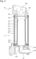
- Fig. 3 is a cross-section taken along and viewed in a direction of an arrow 3-3 line in Fig. 1A .
- the flavor inhaler 10 includes a power source portion 20, a circuit portion 30, and a heating portion 40 in an interior space of the outer housing 11 and of an inner housing 17.
- the top housing 11A and the bottom housing 11B which form the outer housing 11 enclose the inner housing 17 and thus house the inner housing 17 in interior spaces thereof.
- the circuit portion 30 includes a first circuit board 31, a second circuit board 32, and a third circuit board 33 which are electrically connected to one another.
- the first circuit board 31 is disposed, for example, adjacent to one surface of a rectangular power source 21 and extends in the longitudinal direction as illustrated in the drawing.
- a partition wall 34 Provided between the first circuit board 31 and the heating portion 40 is a partition wall 34, which sections off at least part of a region in which the power source portion 20 and the first circuit board 31 are housed.
- the partition wall 34 may be provided with a notch, a through-hole or the like for allowing a fluid communication between a space on the power source portion 20 side and a space on the heating portion 40 side.
- the second circuit board 32 is disposed between the cover 12 and the power source portion 20 on an inner side of the top housing 11A and extends in a direction orthogonal to a direction the first circuit board 31 extends.
- the switch 13 is disposed adjacent to the second circuit board 32. When pushed down by the user, the switch 13 partially contacts the second circuit board 32.
- the third circuit board 33 is disposed to extend in the longitudinal direction in a space formed on an opposite side of the heating portion 40 from the opening 12a (see Fig. 1B ).
- the third circuit board 33 includes a main surface on which various kinds of electronic components are mounted.
- the third circuit board 33 may be disposed within the bottom housing 11B so that the main surface is inclined with respect to the longitudinal direction. This makes it possible to enlarge the main surface of the third circuit board 33, thereby making effective use of a space in the bottom housing 11B.
- the first circuit board 31, the second circuit board 32, and the third circuit board 33 each include, for example, a microprocessor and the like and are capable of controlling power supply from the power source portion 20 to the heating portion 40. This enables the first circuit board 31, the second circuit board 32, and the third circuit board 33 to control the heating of the flavor generating article 110 which is performed by the heating portion 40.
- the power source portion 20 includes the power source 21 that is electrically connected to the first circuit board 31, the second circuit board 32, and the third circuit board 33.
- the power source 21 may be, for example, a rechargeable or non-rechargeable battery.
- the power source 21 is electrically connected to the heating portion 40 through at least one of the first circuit board 31, the second circuit board 32, and the third circuit board 33.
- the power source 21 is thus capable of supplying electric power to the heating portion 40 so that the flavor generating article 110 may be properly heated. As illustrated in the drawing, the power source 21 is disposed in parallel with the heating portion 40. If the power source 21 is increased in size, therefore, the flavor inhaler 10 does not have to be increased in longitudinal length.
- the flavor inhaler 10 includes a terminal 22 that is connectable to an external power source.
- the terminal 22 can be connected, for example, to a cable of a micro USB or the like. If the power source 21 is a rechargeable battery, current can be imparted from the external power source to the power source 21 to recharge the power source 21 by connecting the terminal 22 with an external power source.
- a data transmission cable of a micro USB or the like may be connected to the terminal 22 so that data relevant to the actuation of the flavor inhaler 10 may be transmitted to an external device.
- the heating portion 40 includes the heating assembly 41 extending in the longitudinal direction, an inlet pipe 50 having a substantially L-shaped section, and the insertion guide member 60 having a substantially cylindrical shape, as illustrated in the drawing.
- the heating assembly 41 includes a plurality of cylindrical members and is formed into a cylindrical body as a whole.
- the heating assembly 41 is configured to be able to house a part of the flavor generating article 110 in the inside thereof.
- the heating assembly 41 functions to define a channel of air to be supplied to the flavor generating article 110 and also functions to heat the flavor generating article 110 from an outer periphery of the flavor generating article 110.
- the first vent hole 15 and a second vent hole 18 for introducing air into the heating assembly 41 are formed in the bottom housing 11B.
- the first vent hole 15 is in a fluid communication with an upstream end of a channel extending through the inlet pipe 50 to the heating assembly 41.
- the first vent hole 15 comes into a fluid communication with an upstream end of the heating assembly 41 through a through-channel of the inlet pipe 50.
- the second vent hole 18 is in a fluid communication with an upstream end of an air channel 18A formed between the outer housing 11 and the inner housing 17.
- the air channel 18A has a downstream end that is in a fluid communication with the upstream end of the channel extending through the inlet pipe 50, so that the second vent hole 18, like the first vent hole 15, eventually comes into a fluid communication with the heating assembly 41.
- the heating assembly 41 has a downstream end that is in a fluid communication with an upstream end of a channel extending through the insertion guide member 60 to the opening 12a illustrated in Fig. 1B .
- the flavor generating article 110 is inserted from the opening 12a of the cover 12 into the flavor inhaler 10 as illustrated in Fig. 1B and passes through the insertion guide member 60. A part of the flavor generating article 110 is then disposed inside the heating assembly 41.
- the insertion guide member 60 is therefore preferably formed so that an opening on the cover 12 side is larger than an opening on the downstream side of the heating assembly 41. This facilitates the insertion of the flavor generating article 110 from the opening 12a into the insertion guide member 60.
- a side of the heating assembly 41 which is close to the first vent hole 15 and the second vent hole 18 (side close to the inlet pipe 50) is an upstream side
- a side of the heating assembly 41 which is close to the opening 12a (side close to the insertion guide member 60) is a downstream side.
- Fig. 4 is a cross-section of the heating portion 40.
- the heating portion 40 includes the heating assembly 41, the inlet pipe 50, and the insertion guide member 60.
- the heating assembly 41 includes a cup-like container (heat transmitting member) 42 forming a chamber that is capable of housing the flavor generating article 110, a heating member 43 configured to heat the flavor generating article 110, a heat shrinkable tube (fixing member) 44, and a heat insulating portion 45.
- the container 42 is provided at one end with a first opening 42a through which the flavor generating article 110 is inserted into the container 42, and at the other end with a second opening 42b that allows air supply to the flavor generating article 110.
- the container 42 is thus configured to be able to house the flavor generating article 110.
- the container 42 includes a second surface configured to face the flavor generating article 110 when the flavor generating article 110 is fitted in the heating member 43.
- the container 42 includes an inner peripheral surface (second surface) that encloses an outer periphery of the flavor generating article 110 inserted from the first opening 42a and contacts at least part of an outer peripheral surface of the flavor generating article 110.
- the container 42 has an inner diameter that is gradually increased in a direction from the second opening 42b side toward the first opening 42a side, that is, from an opposite side from the first opening 42a toward the first opening 42a, in the vicinity of the first opening 42a. This facilitates the insertion of the flavor generating article 110 from the first opening 42a into the container 42.
- the container 42 further includes a bottom wall 42d against which a tip end of the flavor generating article 110 inserted from the first opening 42a hits.
- the second opening 42b is a through-hole that is formed in the bottom wall 42d of the container 42.
- the second opening 42b is located on an upstream side of an air flow, and the first opening 42a is located on a downstream side of the air flow.
- Formed in an inner peripheral surface of the container 42 is a boss (protrusion) 42c.
- the boss 42c is configured to press the outer peripheral surface of the inserted flavor generating article 110 radially inward.
- the heating member 43 may be a flexible polyimide heater that comprises, for example, a heating resistor (heat generator) made of stainless steel or the like which is sandwiched between two films (substrates) made of PI (polyimide) or the like.
- the heating member 43 is so disposed as to contact the container 42.
- the heating member 43 is disposed in an outer peripheral surface (first surface) of the container 42, and an interior surface of the heating member 43 is in tight contact with an exterior surface of the container 42.
- the heating member 43 is disposed along the outer peripheral surface of the container 42 and is therefore deformed into a substantially cylindrical shape as a whole.
- the heating member 43 generates the heat to be applied to the flavor generating article 110.
- the container 42 is made of a highly heat-conductive metal material, such as steel use stainless. The heat generated in the heating member 43 is accordingly transmitted to the entire container 42, which heats the flavor generating article 110 inserted in the container 42.
- the heat shrinkable tube 44 has a cylindrical shape and keeps the heating member 43 in tight contact with the container 42.
- the heat shrinkable tube 44 is thermally shrunk by being applied with heat in a position disposed on an outer peripheral side of the heating member 43.
- the heat shrinkable tube 44 thus applies pressure to the heating member 43 so as to press the heating member 43 against the container 42.
- the heat shrinkable tube 44 is thermally shrunk while covering part of a downstream side of the inlet pipe 50.
- the heat shrinkable tube 44 thus brings the container 42 and the inlet pipe 50 into tight contact.
- the heat insulating portion 45 is a cylindrical member having a double-tube structure.
- the heat insulating portion 45 is disposed at predetermined distance from the heat shrinkable tube 44 in a radially (direction orthogonal to the longitudinal direction) outward direction.
- the heat insulating portion 45 is made of a metal material, such as steel use stainless, as with the container 42.
- the heat insulating portion 45 includes an inner tubular member 45a, an outer tubular member 45b, a first ring-like member 45c, and a second ring-like member 45d.
- the inner tubular member 45a and the outer tubular member 45b are disposed side by side in a radial direction of the inserted flavor generating article 110.
- the first ring-like member 45c is disposed on a downstream side of the inner tubular member 45a and the outer tubular member 45b
- the second ring-like member 45d is disposed on an upstream side of the inner tubular member 45a and the outer tubular member 45b
- the heat insulating portion 45 may be a vacuum insulating material having depressurized air or vacuum inside the double-tube structure.
- the heat generated from the heating member 43 becomes less transmittable to the outside of the heating assembly 41 by depressurizing a space formed by the inner tubular member 45a, the outer tubular member 45b, the first ring-like member 45c, and the second ring-like member 45d.
- the inlet pipe 50 is made, for example, of resin material.
- the inlet pipe 50 is in a fluid communication with the container 42 through the second opening 42b and introduces air into the container 42.
- the inlet pipe 50 is a member forming a pipe including a downstream end 50a engaged with an upstream end (second opening 42b-side end portion) of the container 42, and an upstream end 50b on an opposite side from the downstream end 50a.
- the inlet pipe 50 forms an inner channel that introduces air toward the second opening 42b of the container 42.
- the inlet pipe 50 illustrated in Fig. 4 forms the inner channel that is bent into an L-like shape.
- the upstream end 50b of the inlet pipe 50 is disposed close or adjacent to the first vent hole 15 and the air channel 18A which are illustrated in Fig. 3 .
- the insertion guide member 60 is made, for example, of resin material.
- the insertion guide member 60 is in a fluid communication with the container 42 through the first opening 42a.
- the insertion guide member 60 is provided between the cover 12 including the opening 12a (see Fig. 1B ) and a downstream end of the heating assembly 41 and guides the insertion of the flavor generating article 110 into the container 42.
- the insertion guide member 60 is a member including an upstream end 60a engaged with a downstream end (first opening 42a-side end portion) of the container 42, and an opening 60b on an opposite side from the upstream end 60a.
- the upstream end 60a (first opening 42a-side end portion) of the insertion guide member 60 encloses an outer periphery of the downstream end of the container 42.
- a predetermined gap is provided between the insertion guide member 60 and the container 42.
- the upstream end of the insertion guide member 60 has an inner diameter that is larger than an outer diameter of the downstream end of the container 42.
- the opening 60b is in a fluid communication with the opening 12a (see Fig. 1B ) of the cover 12 and so configured that the flavor generating article 110 can be inserted therein.
- Fig. 5 is a developed view of the heating member 43 disposed along an outer peripheral surface of the container 42.
- the heating member 43 includes a heating resistor 43a that generates heat, an insulating polyimide film 43b comprising two films between which the heating resistor 43a is sandwiched to be supported, and a wire portion 43c that is electrically connected to the power source 21 (see Fig. 3 ).
- the heating resistor 43a comprises three systems.
- the heating resistor 43a and the polyimide film 43b form a heat generation region 43d in which the heat resistor 43a is disposed, and a non-heat generation region 43e which is located adjacent to the heat generation region 43d and in which the heat resistor 43a is not disposed.
- Fig. 6 is an enlarged cross-section focusing on the container 42, the heating member 43, and a heat shrinkable tube 44.
- the heating member 43 is disposed in the outer peripheral surface of the container 42.
- the non-heat generation region 43e in which the heating resistor 43a is not disposed extends from the heat generation region 43d in which the heating resistor 43a is disposed toward the first opening 42a.
- the heat shrinkable tube 44 is disposed to enclose an outer periphery of the heating member 43.
- the boss 42c is provided in the inner peripheral surface of the container 42 so as to be located in a region that coincides with the non-heat generation region 43e of the heating member 43 which is disposed in the outer peripheral surface of the container 42. This means that the boss 42c is located away from the heat generation region 43d of the heating member 43.
- the boss 42c may be formed by embossing or formed of a convex member fixed on the inner peripheral surface of the container 42 as long as the boss 42c includes a spherical surface.
- the boss 42c may be made of either metallic or non-metallic material.
- a first opening 42a-side end portion of the heat shrinkable tube 44 is disposed to extend further than the boss 42c toward the first opening 42a in the longitudinal direction.
- the first opening 42a-side end portion of the heat insulating portion 45 is disposed to extend further than the boss 42c toward the first opening 42a in the longitudinal direction.
- the boss 42c is provided in the region that coincides with the non-heat generation region 43e of the heating member 43 which is disposed in the outer peripheral surface of the container 42, the flavor generating article 110 can be heated in an even manner. If a boss is formed by embossing in the inner peripheral surface of the container 42 which coincides with the heat generation region 43d of the heating member 43, a gap is formed on a back side of the boss, which makes uneven the heat transmission to the flavor generating article 110.
- a boss is formed by attaching a convex member onto the inner peripheral surface of the container 42 which coincides with the heat generation region 43d of the heating member 43, the container 42 becomes thicker by amount of thickness of the boss, which increases distance from the inner peripheral surface of the container 42 to the heating member 43. Accordingly, the heat transmission to the flavor generating article 110 becomes uneven. If the boss 42c is so formed as to avoid the heat generation region 43d, the flavor generating article 110 can be heated in the even manner.
- the boss 42c is provided in the region that coincides with the non-heat generation region 43e of the heating member 43 which is disposed in the outer peripheral surface of the container 42, it is possible to suppress a damage to the flavor generating article 110 and at the same time hold the flavor generating article 110 inserted in the container 42. If a boss is formed in the vicinity of the first opening 42a, a longitudinal wide area of the flavor generating article 110 comes into frictional contact with the boss during the insertion of the flavor generating article 110. The flavor generating article 110 is then likely to be damaged in an outer surface thereof.
- the boss 42c is formed in the region coinciding with the non-heat generation region 43e, so that the area where the flavor generating article 110 comes into frictional contact with the boss 42c is decreased. It is therefore possible to suppress a damage to the flavor generating article 110, and at the same time hold the flavor generating article 110 inserted in the container 42.
- the boss 42c is prevented from being degraded in ability of holding the flavor generating article 110 since metal has resistance to friction even if the insertion and removal of the flavor generating article 110 are repeated.
- Fig. 7 is an enlarged view focusing on the container 42 and the heating member 43.
- the heating member 43 is a sheet that is wrapped around the outer periphery of the container 42 over the entire circumference, and circumferential side end portions of the sheet meet each other (see a vertical line at the center of the heating member 43 in Fig. 7 ).
- a first band-like region 43f Formed in the non-heat generation region 43e of the heating member 43 is a first band-like region 43f extending along the circumferential direction of the outer peripheral surface of the container 42.
- the first band-like region 43f is formed in an end portion of the heating member 43 which is located on a side close to the first opening 42a of the container 42.
- the boss 42c is provided in a region that coincides with the first band-like region 43f of the heating member 43 which is disposed in the outer peripheral surface of the container 42.
- the boss 42c may comprise a plurality of bosses 42c provided along an extending direction of the first band-like region 43f.
- the flavor generating article 110 inserted in the container 42 can be held in a stable manner. If a boss is formed on the second opening 42b (see Fig. 4 ) side of the container 42, a portion close to the tip end of the flavor generating article 110 is held, and there is a possibility that the flavor generating article 110 oscillates around the boss.
- the flavor generating article 110 can be held in the stable manner by forming the boss 42c in the region coinciding with the first band-like region 43f.
- the flavor generating article 110 can be held in a more stable manner by providing the plurality of bosses 42c.
- Fig. 8 is another enlarged view focusing on the container and the heating member.
- the heating member 43 is a sheet that is wrapped around the outer periphery of the container 42 over the entire circumference, and circumferential side end portions of the sheet meet together (see a vertical line at the center of the heating member 43 in Fig. 8 ).
- the circumferential side end portions of the sheet may overlap each other at least in a partial manner.
- a second band-like region 43g is formed in the non-heat generation region 43e of the heating member 43.
- the second band-like region 43g extends along the longitudinal direction of the container 42.
- the second band-like region 43g is formed over both the side end portions of the sheet in a radial direction.
- the second band-like region 43g may be formed in a region where the side end portions of the sheet overlap each other at least in the partial manner.
- the boss 42c is provided in a region of the inner peripheral surface of the container 42 which coincides with the second band-like region 43g of the heating member 43 which is disposed in the outer peripheral surface of the container 42.
- the boss 42c may be provided within a range of the heat generation region 43d as viewed in an extending direction of the second band-like region 43g.
- the boss 42c may comprise a plurality of bosses 42c provided along the extending direction of the second band-like region 43g.
- the boss 42c may be provided not only in the region coinciding with the second band-like region 43g but also in the region coinciding with the first band-like region 43f illustrated in Fig. 7 .
- the boss 42c is provided in the region of the inner peripheral surface of the container 42 which coincides with the second band-like region 43g of the heating member 43 which is disposed in the outer peripheral surface of the container 42, and at the same time provided within a range of the heat generation region 43d as viewed in the extending direction of the second band-like region 43g, it is possible to reduce a damage to the flavor generating article 110 and hold the flavor generating article 110 inserted in the container 42.
- a frictional contact area of the flavor generating article 110 with respect to the boss 42c can be made narrower as compared to when the boss 42c is formed in a region coinciding with the first band-like region 43f, so that a damage to the flavor generating article 110 can be reduced.
- the flavor generating article 110 can be held in a more stable manner by providing the plurality of bosses 42c.
- a first mode provides a heating assembly comprising a heating member configured to heat a flavor generating article, and a heat transmitting member configured to transmit heat generated in the heating member to the flavor generating article.
- the heating member includes a heat generator configured to generate heat and an insulating substrate configured to support the heat generator.
- the heat generator and the substrate form a heat generation region in which the heat generator is disposed and a non-heat generation region which is located adjacent to the heat generation region and in which the heat generator is not disposed.
- the heat transmitting member includes a first surface in which the heating member is disposed, a second surface configured to face the flavor generating article when the flavor generating article is fitted in the heating member, and a protrusion that is provided in a region of the second surface which coincides with the non-heat generation region of the heating member disposed in the first surface, the protrusion being configured to press and hold the flavor generating article fitted in the heating member.
- the heat transmitting member forms a chamber that is capable of housing the flavor generating article, and the chamber includes outer and inner peripheral surfaces that respectively form first and second surfaces of the heat transmitting member.
- the non-heat generation region includes a first band-like region extending along a circumferential direction of the outer peripheral surface, and the protrusion is provided in a region of the inner peripheral surface which coincides with the first band-like region.
- the protrusion comprises a plurality of protrusions provided along an extending direction of the first band-like region.
- the chamber in the heating assembly of the third or fourth mode, includes a first opening for inserting the flavor generating article, and the first band-like region is formed in an end portion of the heating member which is located on a side close to the first opening of the heat transmitting member.
- the heating assembly further comprises a fixing member enclosing an outer periphery of the heating member and configured to fix the heating member to the heat transmitting member.
- An end portion of the fixing member which is located on a side close to the first opening of the heat transmitting member is disposed closer to the first opening of the heat transmitting member than the protrusion is as viewed in a longitudinal direction of the flavor generating article fitted in the heating member.
- the heating assembly further comprises a heat insulating portion that is disposed away from the heating member in a direction orthogonal to a longitudinal direction of the flavor generating article fitted in the heating member.
- An end portion of the heat insulating portion which is located on a side close to the first opening of the heat transmitting member is disposed closer to the first opening of the heat transmitting member than the protrusion is as viewed in the longitudinal direction.
- the heat transmitting member includes a portion having an inner diameter that is gradually increased in a direction from an opposite side from the first opening toward the first opening.
- the heat transmitting member is in a fluid communication with an insertion guide member configured to guide insertion of the flavor generating article into the heat transmitting member through the first opening.
- the insertion guide member has an inner diameter that is gradually increased with distance away from the first opening.
- the chamber in the heating assembly of any one of the second to 10th modes, includes a second opening that allows air supply to the flavor generating article.
- the non-heat generation region includes a second band-like region extending along a longitudinal direction of the flavor generating article fitted in the heating member, and the protrusion is provided in a region of the second surface which coincides with the second band-like region.
- the protrusion is provided within an extending range of the heat generation region as viewed in the extending direction of the second band-like region.
- the protrusion comprises a plurality of protrusions provided along the extending direction of the second band-like region.
- the heating member is a sheet that is wrapped around an outer periphery of the heat transmitting member, and the second band-like region is formed over both side end portions of the sheet in a direction orthogonal to the longitudinal direction of the flavor generating article fitted in the heating member.
- the second band-like region is a region in which the side end portions of the sheet meet each other at least in a partial manner.
- the heat generator is sandwiched between a pair of substrates.
- An 18th mode provides a flavor inhaler comprising the heating assembly of any one of the first to 17th modes.
Landscapes
- Packages (AREA)
- Disinfection, Sterilisation Or Deodorisation Of Air (AREA)
- Cookers (AREA)
Claims (18)
- Ensemble chauffant (41) comprenant :un élément chauffant (43) configuré pour chauffer un article de génération d'arôme (110), etun élément de transmission de chaleur (42) configuré pour transmettre la chaleur générée dans l'élément chauffant à l'article de génération d'arôme,dans lequel l'élément chauffant inclut :un générateur de chaleur (43a) configuré pour générer de la chaleur, etun substrat isolant (43b) configuré pour soutenir le générateur de chaleur,dans lequel le générateur de chaleur et le substrat forment une région de génération de chaleur (43d) dans laquelle le générateur de chaleur est disposé et une région de non-génération de chaleur (43e) qui est située de façon adjacente à la région de génération de chaleur et dans laquelle le générateur de chaleur n'est pas disposé,caractérisé en ce que l'élément de transmission de chaleur inclut :une première surface dans laquelle l'élément chauffant est disposé ;une seconde surface configurée pour être face à l'article de génération d'arôme lorsque l'article de génération d'arôme est installé dans l'élément chauffant, etune saillie (42c) qui est prévue dans une région de la seconde surface qui coïncide avec la région de non-génération de chaleur de l'élément chauffant disposée dans la première surface, la saillie étant configurée pour appuyer sur l'article de génération d'arôme installé dans l'élément chauffant et le maintenir.
- Ensemble chauffant selon la revendication 1,dans lequel l'élément de transmission de chaleur forme une chambre qui est apte à loger l'article de génération d'arôme, etdans lequel la chambre inclut des surfaces périphériques externe et interne qui forment respectivement les première et seconde surfaces de l'élément de transmission de chaleur.
- Ensemble chauffant selon la revendication 2,dans lequel la région de non-génération de chaleur inclut une première région de type bande s'étendant le long d'une direction circonférentielle de la surface périphérique externe, etdans lequel la saillie est prévue dans une région de la surface périphérique interne qui coïncide avec la première région de type bande.
- Ensemble chauffant selon la revendication 3,
dans lequel la saillie comprend une pluralité de saillies prévues le long d'une direction d'extension de la première région de type bande. - Ensemble chauffant selon la revendication 3 ou la revendication 4,dans lequel la chambre inclut une première ouverture pour l'insertion de l'article de génération d'arôme, etdans lequel la première région de type bande est formée dans une partie d'extrémité de l'élément chauffant qui est située sur un côté proche de la première ouverture de l'élément de transmission de chaleur.
- Ensemble chauffant selon la revendication 5, comprenant en outre :un élément de fixation entourant une périphérie externe de l'élément chauffant et configuré pour fixer l'élément chauffant à l'élément de transmission de chaleur,dans lequel une partie d'extrémité de l'élément de fixation qui est située sur un côté proche de la première ouverture de l'élément de transmission de chaleur est disposée plus proche de la première ouverture de l'élément de transmission de chaleur que ne l'est la saillie telle que vue dans une direction longitudinale de l'article de génération d'arôme installé dans l'élément chauffant.
- Ensemble chauffant selon la revendication 5 ou la revendication 6, comprenant en outre :une partie d'isolation thermique qui est disposée à l'opposé de l'élément chauffant dans une direction orthogonale à une direction longitudinale de l'article de génération d'arôme installé dans l'élément chauffant,dans lequel une partie d'extrémité de la partie d'isolation thermique qui est située sur un côté proche de la première ouverture de l'élément de transmission de chaleur est disposée plus proche de la première ouverture de l'élément de transmission de chaleur que ne l'est la saillie, telle que vue dans la direction longitudinale.
- Ensemble chauffant selon l'une quelconque des revendications 5 à 7,
dans lequel l'élément de transmission de chaleur inclut une partie présentant un diamètre interne qui est progressivement augmenté dans une direction d'un côté opposé à la première ouverture vers la première ouverture. - Ensemble chauffant selon l'une quelconque des revendications 5 à 8,
dans lequel l'élément de transmission de chaleur est en communication fluidique avec un élément de guidage d'insertion configuré pour guider l'insertion de l'article de génération d'arôme dans l'élément de transmission de chaleur à travers la première ouverture. - Ensemble chauffant selon la revendication 9,
dans lequel l'élément de guidage d'insertion présente un diamètre interne qui est progressivement augmenté avec une distance à l'opposé de la première ouverture. - Ensemble chauffant selon l'une quelconque des revendications 2 à 10,
dans lequel la chambre inclut une seconde ouverture qui permet une alimentation en air de l'article de génération d'arôme. - Ensemble chauffant selon l'une quelconque des revendications 1 à 11,dans lequel la région de non-génération de chaleur inclut une seconde région de type bande s'étendant le long d'une direction longitudinale de l'article de génération d'arôme installé dans l'élément chauffant, etdans lequel la saillie est prévue dans une région de la seconde surface qui coïncide avec la seconde région de type bande.
- Ensemble chauffant selon la revendication 12,
dans lequel la saillie est prévue à l'intérieur d'une plage d'extension de la région de génération de chaleur telle que vue dans la direction d'extension de la seconde région de type bande. - Ensemble chauffant selon la revendication 12 ou la revendication 13,
la saillie comprend une pluralité de saillies prévues le long de la direction d'extension de la seconde région de type bande. - Ensemble chauffant selon l'une quelconque des revendications 12 à 14,dans lequel l'élément chauffant est une feuille qui est enroulée autour d'une périphérie externe de l'élément de transmission de chaleur, etdans lequel la seconde région de type bande est formée sur les deux parties d'extrémité latérales de la feuille dans une direction orthogonale à la direction longitudinale de l'article de génération d'arôme installé dans l'élément chauffant.
- Ensemble chauffant selon la revendication 15,
dans lequel la seconde région de type bande est une région dans laquelle les parties d'extrémité latérales de la feuille se rejoignent au moins de manière partielle. - Ensemble chauffant selon l'une quelconque des revendications 1 à 16,
dans lequel le générateur de chaleur est pris en sandwich entre une paire de substrats. - Inhalateur d'arôme comprenant l'ensemble chauffant selon l'une quelconque des revendications 1 à 17.
Applications Claiming Priority (1)
| Application Number | Priority Date | Filing Date | Title |
|---|---|---|---|
| PCT/JP2019/026178 WO2021001910A1 (fr) | 2019-07-01 | 2019-07-01 | Ensemble chauffant et inhalateur d'arôme |
Publications (3)
| Publication Number | Publication Date |
|---|---|
| EP3995015A1 EP3995015A1 (fr) | 2022-05-11 |
| EP3995015A4 EP3995015A4 (fr) | 2023-03-15 |
| EP3995015B1 true EP3995015B1 (fr) | 2023-11-08 |
Family
ID=74100971
Family Applications (1)
| Application Number | Title | Priority Date | Filing Date |
|---|---|---|---|
| EP19936279.9A Active EP3995015B1 (fr) | 2019-07-01 | 2019-07-01 | Ensemble chauffant et inhalateur d'arôme |
Country Status (5)
| Country | Link |
|---|---|
| EP (1) | EP3995015B1 (fr) |
| JP (1) | JP7204918B2 (fr) |
| PL (1) | PL3995015T3 (fr) |
| TW (1) | TW202102143A (fr) |
| WO (1) | WO2021001910A1 (fr) |
Families Citing this family (1)
| Publication number | Priority date | Publication date | Assignee | Title |
|---|---|---|---|---|
| WO2022264312A1 (fr) * | 2021-06-16 | 2022-12-22 | 日本たばこ産業株式会社 | Système générant un aérosol |
Family Cites Families (5)
| Publication number | Priority date | Publication date | Assignee | Title |
|---|---|---|---|---|
| US5954979A (en) | 1997-10-16 | 1999-09-21 | Philip Morris Incorporated | Heater fixture of an electrical smoking system |
| US20170055580A1 (en) * | 2015-08-31 | 2017-03-02 | British American Tobacco (Investments) Limited | Apparatus for heating smokable material |
| RU2728255C2 (ru) * | 2016-04-27 | 2020-07-28 | Филип Моррис Продактс С.А. | Генерирующее аэрозоль устройство с фиксирующими средствами |
| TW201740827A (zh) | 2016-05-13 | 2017-12-01 | 英美煙草(投資)有限公司 | 用於加熱可吸菸材料的裝置及方法 |
| CN206776746U (zh) * | 2017-06-07 | 2017-12-22 | 常州市派腾电子技术服务有限公司 | 雾化装置及其电子烟 |
-
2019
- 2019-07-01 EP EP19936279.9A patent/EP3995015B1/fr active Active
- 2019-07-01 JP JP2021529585A patent/JP7204918B2/ja active Active
- 2019-07-01 WO PCT/JP2019/026178 patent/WO2021001910A1/fr unknown
- 2019-07-01 PL PL19936279.9T patent/PL3995015T3/pl unknown
- 2019-08-08 TW TW108128304A patent/TW202102143A/zh unknown
Also Published As
| Publication number | Publication date |
|---|---|
| EP3995015A4 (fr) | 2023-03-15 |
| EP3995015A1 (fr) | 2022-05-11 |
| WO2021001910A1 (fr) | 2021-01-07 |
| PL3995015T3 (pl) | 2024-03-04 |
| JP7204918B2 (ja) | 2023-01-16 |
| TW202102143A (zh) | 2021-01-16 |
| JPWO2021001910A1 (fr) | 2021-01-07 |
Similar Documents
| Publication | Publication Date | Title |
|---|---|---|
| JP7185796B2 (ja) | 喫煙システム | |
| KR102565579B1 (ko) | 적응성 있는 에어로졸 발생 시스템 | |
| US12059031B2 (en) | Housing and flavor aspirator provided with same | |
| EP3995015B1 (fr) | Ensemble chauffant et inhalateur d'arôme | |
| EP3995014A1 (fr) | Ensemble de chauffage et inhalateur d'arôme | |
| EP3995013A1 (fr) | Inhalateur d'arôme et élément de guidage d'insertion | |
| JP7267423B2 (ja) | 香味吸引器 | |
| JP7267422B2 (ja) | 香味吸引器 | |
| JP7296021B2 (ja) | 筐体およびこれを備えた香味吸引器 | |
| JP2023113897A (ja) | 筐体およびこれを備えた香味吸引器 | |
| WO2022224428A1 (fr) | Inhalateur d'arôme | |
| RU2774289C1 (ru) | Корпус и снабженное им устройство для вдыхания ароматизатора | |
| EP4094599A1 (fr) | Dispositif d'aspiration | |
| EP4245168A1 (fr) | Article de génération d'arôme | |
| CA3188844A1 (fr) | Cartomiseur pour un dispositif de generation d'aerosol avec prevention de fuite |
Legal Events
| Date | Code | Title | Description |
|---|---|---|---|
| STAA | Information on the status of an ep patent application or granted ep patent |
Free format text: STATUS: THE INTERNATIONAL PUBLICATION HAS BEEN MADE |
|
| PUAI | Public reference made under article 153(3) epc to a published international application that has entered the european phase |
Free format text: ORIGINAL CODE: 0009012 |
|
| STAA | Information on the status of an ep patent application or granted ep patent |
Free format text: STATUS: REQUEST FOR EXAMINATION WAS MADE |
|
| 17P | Request for examination filed |
Effective date: 20220128 |
|
| AK | Designated contracting states |
Kind code of ref document: A1 Designated state(s): AL AT BE BG CH CY CZ DE DK EE ES FI FR GB GR HR HU IE IS IT LI LT LU LV MC MK MT NL NO PL PT RO RS SE SI SK SM TR |
|
| DAV | Request for validation of the european patent (deleted) | ||
| DAX | Request for extension of the european patent (deleted) | ||
| REG | Reference to a national code |
Ref country code: DE Ref legal event code: R079 Ref document number: 602019041287 Country of ref document: DE Free format text: PREVIOUS MAIN CLASS: A24F0047000000 Ipc: A24F0040460000 Ref country code: DE Ref legal event code: R079 Free format text: PREVIOUS MAIN CLASS: A24F0047000000 Ipc: A24F0040460000 |
|
| A4 | Supplementary search report drawn up and despatched |
Effective date: 20230210 |
|
| RIC1 | Information provided on ipc code assigned before grant |
Ipc: A24F 40/20 20200101ALN20230206BHEP Ipc: A24F 40/46 20200101AFI20230206BHEP |
|
| GRAP | Despatch of communication of intention to grant a patent |
Free format text: ORIGINAL CODE: EPIDOSNIGR1 |
|
| STAA | Information on the status of an ep patent application or granted ep patent |
Free format text: STATUS: GRANT OF PATENT IS INTENDED |
|
| RIC1 | Information provided on ipc code assigned before grant |
Ipc: A24F 40/20 20200101ALN20230427BHEP Ipc: A24F 40/46 20200101AFI20230427BHEP |
|
| INTG | Intention to grant announced |
Effective date: 20230524 |
|
| GRAS | Grant fee paid |
Free format text: ORIGINAL CODE: EPIDOSNIGR3 |
|
| GRAA | (expected) grant |
Free format text: ORIGINAL CODE: 0009210 |
|
| STAA | Information on the status of an ep patent application or granted ep patent |
Free format text: STATUS: THE PATENT HAS BEEN GRANTED |
|
| P01 | Opt-out of the competence of the unified patent court (upc) registered |
Effective date: 20230925 |
|
| AK | Designated contracting states |
Kind code of ref document: B1 Designated state(s): AL AT BE BG CH CY CZ DE DK EE ES FI FR GB GR HR HU IE IS IT LI LT LU LV MC MK MT NL NO PL PT RO RS SE SI SK SM TR |
|
| REG | Reference to a national code |
Ref country code: GB Ref legal event code: FG4D |
|
| REG | Reference to a national code |
Ref country code: CH Ref legal event code: EP |
|
| REG | Reference to a national code |
Ref country code: DE Ref legal event code: R096 Ref document number: 602019041287 Country of ref document: DE |
|
| REG | Reference to a national code |
Ref country code: IE Ref legal event code: FG4D |
|
| REG | Reference to a national code |
Ref country code: GR Ref legal event code: EP Ref document number: 20230402371 Country of ref document: GR Effective date: 20240110 |
|
| REG | Reference to a national code |
Ref country code: LT Ref legal event code: MG9D |
|
| REG | Reference to a national code |
Ref country code: NL Ref legal event code: MP Effective date: 20231108 |
|
| PG25 | Lapsed in a contracting state [announced via postgrant information from national office to epo] |
Ref country code: IS Free format text: LAPSE BECAUSE OF FAILURE TO SUBMIT A TRANSLATION OF THE DESCRIPTION OR TO PAY THE FEE WITHIN THE PRESCRIBED TIME-LIMIT Effective date: 20240308 |
|
| PG25 | Lapsed in a contracting state [announced via postgrant information from national office to epo] |
Ref country code: LT Free format text: LAPSE BECAUSE OF FAILURE TO SUBMIT A TRANSLATION OF THE DESCRIPTION OR TO PAY THE FEE WITHIN THE PRESCRIBED TIME-LIMIT Effective date: 20231108 |
|
| REG | Reference to a national code |
Ref country code: AT Ref legal event code: MK05 Ref document number: 1628804 Country of ref document: AT Kind code of ref document: T Effective date: 20231108 |
|
| PG25 | Lapsed in a contracting state [announced via postgrant information from national office to epo] |
Ref country code: NL Free format text: LAPSE BECAUSE OF FAILURE TO SUBMIT A TRANSLATION OF THE DESCRIPTION OR TO PAY THE FEE WITHIN THE PRESCRIBED TIME-LIMIT Effective date: 20231108 |
|
| PG25 | Lapsed in a contracting state [announced via postgrant information from national office to epo] |
Ref country code: AT Free format text: LAPSE BECAUSE OF FAILURE TO SUBMIT A TRANSLATION OF THE DESCRIPTION OR TO PAY THE FEE WITHIN THE PRESCRIBED TIME-LIMIT Effective date: 20231108 |
|
| PG25 | Lapsed in a contracting state [announced via postgrant information from national office to epo] |
Ref country code: ES Free format text: LAPSE BECAUSE OF FAILURE TO SUBMIT A TRANSLATION OF THE DESCRIPTION OR TO PAY THE FEE WITHIN THE PRESCRIBED TIME-LIMIT Effective date: 20231108 |
|
| PG25 | Lapsed in a contracting state [announced via postgrant information from national office to epo] |
Ref country code: NL Free format text: LAPSE BECAUSE OF FAILURE TO SUBMIT A TRANSLATION OF THE DESCRIPTION OR TO PAY THE FEE WITHIN THE PRESCRIBED TIME-LIMIT Effective date: 20231108 Ref country code: LT Free format text: LAPSE BECAUSE OF FAILURE TO SUBMIT A TRANSLATION OF THE DESCRIPTION OR TO PAY THE FEE WITHIN THE PRESCRIBED TIME-LIMIT Effective date: 20231108 Ref country code: IS Free format text: LAPSE BECAUSE OF FAILURE TO SUBMIT A TRANSLATION OF THE DESCRIPTION OR TO PAY THE FEE WITHIN THE PRESCRIBED TIME-LIMIT Effective date: 20240308 Ref country code: ES Free format text: LAPSE BECAUSE OF FAILURE TO SUBMIT A TRANSLATION OF THE DESCRIPTION OR TO PAY THE FEE WITHIN THE PRESCRIBED TIME-LIMIT Effective date: 20231108 Ref country code: BG Free format text: LAPSE BECAUSE OF FAILURE TO SUBMIT A TRANSLATION OF THE DESCRIPTION OR TO PAY THE FEE WITHIN THE PRESCRIBED TIME-LIMIT Effective date: 20240208 Ref country code: AT Free format text: LAPSE BECAUSE OF FAILURE TO SUBMIT A TRANSLATION OF THE DESCRIPTION OR TO PAY THE FEE WITHIN THE PRESCRIBED TIME-LIMIT Effective date: 20231108 Ref country code: PT Free format text: LAPSE BECAUSE OF FAILURE TO SUBMIT A TRANSLATION OF THE DESCRIPTION OR TO PAY THE FEE WITHIN THE PRESCRIBED TIME-LIMIT Effective date: 20240308 |
|
| PG25 | Lapsed in a contracting state [announced via postgrant information from national office to epo] |
Ref country code: SE Free format text: LAPSE BECAUSE OF FAILURE TO SUBMIT A TRANSLATION OF THE DESCRIPTION OR TO PAY THE FEE WITHIN THE PRESCRIBED TIME-LIMIT Effective date: 20231108 Ref country code: RS Free format text: LAPSE BECAUSE OF FAILURE TO SUBMIT A TRANSLATION OF THE DESCRIPTION OR TO PAY THE FEE WITHIN THE PRESCRIBED TIME-LIMIT Effective date: 20231108 Ref country code: NO Free format text: LAPSE BECAUSE OF FAILURE TO SUBMIT A TRANSLATION OF THE DESCRIPTION OR TO PAY THE FEE WITHIN THE PRESCRIBED TIME-LIMIT Effective date: 20240208 Ref country code: LV Free format text: LAPSE BECAUSE OF FAILURE TO SUBMIT A TRANSLATION OF THE DESCRIPTION OR TO PAY THE FEE WITHIN THE PRESCRIBED TIME-LIMIT Effective date: 20231108 Ref country code: HR Free format text: LAPSE BECAUSE OF FAILURE TO SUBMIT A TRANSLATION OF THE DESCRIPTION OR TO PAY THE FEE WITHIN THE PRESCRIBED TIME-LIMIT Effective date: 20231108 |
|
| PG25 | Lapsed in a contracting state [announced via postgrant information from national office to epo] |
Ref country code: DK Free format text: LAPSE BECAUSE OF FAILURE TO SUBMIT A TRANSLATION OF THE DESCRIPTION OR TO PAY THE FEE WITHIN THE PRESCRIBED TIME-LIMIT Effective date: 20231108 |
|
| PGFP | Annual fee paid to national office [announced via postgrant information from national office to epo] |
Ref country code: CZ Payment date: 20240624 Year of fee payment: 6 |
|
| PG25 | Lapsed in a contracting state [announced via postgrant information from national office to epo] |
Ref country code: SK Free format text: LAPSE BECAUSE OF FAILURE TO SUBMIT A TRANSLATION OF THE DESCRIPTION OR TO PAY THE FEE WITHIN THE PRESCRIBED TIME-LIMIT Effective date: 20231108 |
|
| PG25 | Lapsed in a contracting state [announced via postgrant information from national office to epo] |
Ref country code: SM Free format text: LAPSE BECAUSE OF FAILURE TO SUBMIT A TRANSLATION OF THE DESCRIPTION OR TO PAY THE FEE WITHIN THE PRESCRIBED TIME-LIMIT Effective date: 20231108 Ref country code: SK Free format text: LAPSE BECAUSE OF FAILURE TO SUBMIT A TRANSLATION OF THE DESCRIPTION OR TO PAY THE FEE WITHIN THE PRESCRIBED TIME-LIMIT Effective date: 20231108 Ref country code: EE Free format text: LAPSE BECAUSE OF FAILURE TO SUBMIT A TRANSLATION OF THE DESCRIPTION OR TO PAY THE FEE WITHIN THE PRESCRIBED TIME-LIMIT Effective date: 20231108 Ref country code: DK Free format text: LAPSE BECAUSE OF FAILURE TO SUBMIT A TRANSLATION OF THE DESCRIPTION OR TO PAY THE FEE WITHIN THE PRESCRIBED TIME-LIMIT Effective date: 20231108 |
|
| PGFP | Annual fee paid to national office [announced via postgrant information from national office to epo] |
Ref country code: RO Payment date: 20240628 Year of fee payment: 6 |
|
| REG | Reference to a national code |
Ref country code: DE Ref legal event code: R097 Ref document number: 602019041287 Country of ref document: DE |
|
| PLBE | No opposition filed within time limit |
Free format text: ORIGINAL CODE: 0009261 |
|
| STAA | Information on the status of an ep patent application or granted ep patent |
Free format text: STATUS: NO OPPOSITION FILED WITHIN TIME LIMIT |
|
| PGFP | Annual fee paid to national office [announced via postgrant information from national office to epo] |
Ref country code: DE Payment date: 20240719 Year of fee payment: 6 |
|
| PGFP | Annual fee paid to national office [announced via postgrant information from national office to epo] |
Ref country code: GR Payment date: 20240723 Year of fee payment: 6 |
|
| PGFP | Annual fee paid to national office [announced via postgrant information from national office to epo] |
Ref country code: GB Payment date: 20240725 Year of fee payment: 6 |
|
| 26N | No opposition filed |
Effective date: 20240809 |
|
| PGFP | Annual fee paid to national office [announced via postgrant information from national office to epo] |
Ref country code: FR Payment date: 20240730 Year of fee payment: 6 |