EP3994014B1 - Pneu comprenant un dispositif de surveillance - Google Patents
Pneu comprenant un dispositif de surveillance Download PDFInfo
- Publication number
- EP3994014B1 EP3994014B1 EP20740425.2A EP20740425A EP3994014B1 EP 3994014 B1 EP3994014 B1 EP 3994014B1 EP 20740425 A EP20740425 A EP 20740425A EP 3994014 B1 EP3994014 B1 EP 3994014B1
- Authority
- EP
- European Patent Office
- Prior art keywords
- tyre
- accumulation device
- equal
- support
- monitoring device
- Prior art date
- Legal status (The legal status is an assumption and is not a legal conclusion. Google has not performed a legal analysis and makes no representation as to the accuracy of the status listed.)
- Active
Links
- 238000012806 monitoring device Methods 0.000 title claims description 61
- 238000009825 accumulation Methods 0.000 claims description 90
- 239000012790 adhesive layer Substances 0.000 claims description 31
- 230000001133 acceleration Effects 0.000 claims description 24
- 239000000853 adhesive Substances 0.000 claims description 19
- 230000001070 adhesive effect Effects 0.000 claims description 19
- 239000000463 material Substances 0.000 claims description 15
- 229920002943 EPDM rubber Polymers 0.000 claims description 8
- NIXOWILDQLNWCW-UHFFFAOYSA-N acrylic acid group Chemical group C(C=C)(=O)O NIXOWILDQLNWCW-UHFFFAOYSA-N 0.000 claims description 8
- 239000003522 acrylic cement Substances 0.000 claims description 8
- 239000002390 adhesive tape Substances 0.000 claims description 8
- 238000012545 processing Methods 0.000 claims description 8
- 239000000758 substrate Substances 0.000 claims description 8
- 229920002635 polyurethane Polymers 0.000 claims description 6
- 239000004814 polyurethane Substances 0.000 claims description 6
- 239000004677 Nylon Substances 0.000 claims description 4
- 239000006260 foam Substances 0.000 claims description 4
- 229920001778 nylon Polymers 0.000 claims description 4
- 229920000642 polymer Polymers 0.000 claims description 4
- 239000004642 Polyimide Substances 0.000 claims description 3
- 239000013536 elastomeric material Substances 0.000 claims description 3
- 229920000647 polyepoxide Polymers 0.000 claims description 3
- 229920001721 polyimide Polymers 0.000 claims description 3
- 239000004065 semiconductor Substances 0.000 claims description 3
- 150000001993 dienes Chemical class 0.000 claims description 2
- 239000003822 epoxy resin Substances 0.000 claims description 2
- 229920003207 poly(ethylene-2,6-naphthalate) Polymers 0.000 claims description 2
- 239000011112 polyethylene naphthalate Substances 0.000 claims description 2
- 229920000139 polyethylene terephthalate Polymers 0.000 claims description 2
- 239000005020 polyethylene terephthalate Substances 0.000 claims description 2
- 229920005749 polyurethane resin Polymers 0.000 claims description 2
- 229910052710 silicon Inorganic materials 0.000 claims description 2
- 239000010703 silicon Substances 0.000 claims description 2
- 239000012815 thermoplastic material Substances 0.000 claims description 2
- 239000010410 layer Substances 0.000 description 14
- 238000005096 rolling process Methods 0.000 description 9
- 238000005516 engineering process Methods 0.000 description 7
- 238000013021 overheating Methods 0.000 description 6
- 230000000694 effects Effects 0.000 description 5
- RYGMFSIKBFXOCR-UHFFFAOYSA-N Copper Chemical compound [Cu] RYGMFSIKBFXOCR-UHFFFAOYSA-N 0.000 description 3
- 239000003795 chemical substances by application Substances 0.000 description 3
- 229910052802 copper Inorganic materials 0.000 description 3
- 239000010949 copper Substances 0.000 description 3
- 230000008878 coupling Effects 0.000 description 3
- 238000010168 coupling process Methods 0.000 description 3
- 238000005859 coupling reaction Methods 0.000 description 3
- 238000004519 manufacturing process Methods 0.000 description 3
- 238000005259 measurement Methods 0.000 description 3
- 238000003466 welding Methods 0.000 description 3
- BQCADISMDOOEFD-UHFFFAOYSA-N Silver Chemical compound [Ag] BQCADISMDOOEFD-UHFFFAOYSA-N 0.000 description 2
- 230000000052 comparative effect Effects 0.000 description 2
- 239000002131 composite material Substances 0.000 description 2
- 150000001875 compounds Chemical class 0.000 description 2
- 125000004122 cyclic group Chemical group 0.000 description 2
- 238000000354 decomposition reaction Methods 0.000 description 2
- 239000008393 encapsulating agent Substances 0.000 description 2
- 230000009931 harmful effect Effects 0.000 description 2
- NUJOXMJBOLGQSY-UHFFFAOYSA-N manganese dioxide Chemical compound O=[Mn]=O NUJOXMJBOLGQSY-UHFFFAOYSA-N 0.000 description 2
- 229910052751 metal Inorganic materials 0.000 description 2
- 239000002184 metal Substances 0.000 description 2
- 238000000034 method Methods 0.000 description 2
- 239000002245 particle Substances 0.000 description 2
- 229920005862 polyol Polymers 0.000 description 2
- 150000003077 polyols Chemical class 0.000 description 2
- 230000001681 protective effect Effects 0.000 description 2
- 229910052709 silver Inorganic materials 0.000 description 2
- 239000004332 silver Substances 0.000 description 2
- OKTJSMMVPCPJKN-UHFFFAOYSA-N Carbon Chemical compound [C] OKTJSMMVPCPJKN-UHFFFAOYSA-N 0.000 description 1
- 102100029141 Cyclic nucleotide-gated cation channel beta-1 Human genes 0.000 description 1
- VGGSQFUCUMXWEO-UHFFFAOYSA-N Ethene Chemical compound C=C VGGSQFUCUMXWEO-UHFFFAOYSA-N 0.000 description 1
- JOYRKODLDBILNP-UHFFFAOYSA-N Ethyl urethane Chemical compound CCOC(N)=O JOYRKODLDBILNP-UHFFFAOYSA-N 0.000 description 1
- 239000005977 Ethylene Substances 0.000 description 1
- 101000771075 Homo sapiens Cyclic nucleotide-gated cation channel beta-1 Proteins 0.000 description 1
- 101000979098 Homo sapiens Serine/threonine-protein kinase MAK Proteins 0.000 description 1
- HBBGRARXTFLTSG-UHFFFAOYSA-N Lithium ion Chemical compound [Li+] HBBGRARXTFLTSG-UHFFFAOYSA-N 0.000 description 1
- 239000004721 Polyphenylene oxide Substances 0.000 description 1
- 101000678464 Saccharomyces cerevisiae (strain ATCC 204508 / S288c) 40S ribosomal protein S25-A Proteins 0.000 description 1
- 101000678986 Saccharomyces cerevisiae (strain ATCC 204508 / S288c) 40S ribosomal protein S25-B Proteins 0.000 description 1
- 101000592082 Saccharomyces cerevisiae (strain ATCC 204508 / S288c) 60S ribosomal protein L28 Proteins 0.000 description 1
- 102100023230 Serine/threonine-protein kinase MAK Human genes 0.000 description 1
- XUIMIQQOPSSXEZ-UHFFFAOYSA-N Silicon Chemical compound [Si] XUIMIQQOPSSXEZ-UHFFFAOYSA-N 0.000 description 1
- 239000004433 Thermoplastic polyurethane Substances 0.000 description 1
- ATJFFYVFTNAWJD-UHFFFAOYSA-N Tin Chemical compound [Sn] ATJFFYVFTNAWJD-UHFFFAOYSA-N 0.000 description 1
- 238000004026 adhesive bonding Methods 0.000 description 1
- 229910045601 alloy Inorganic materials 0.000 description 1
- 239000000956 alloy Substances 0.000 description 1
- 239000004411 aluminium Substances 0.000 description 1
- 229910052782 aluminium Inorganic materials 0.000 description 1
- XAGFODPZIPBFFR-UHFFFAOYSA-N aluminium Chemical compound [Al] XAGFODPZIPBFFR-UHFFFAOYSA-N 0.000 description 1
- 230000015572 biosynthetic process Effects 0.000 description 1
- JWVAUCBYEDDGAD-UHFFFAOYSA-N bismuth tin Chemical compound [Sn].[Bi] JWVAUCBYEDDGAD-UHFFFAOYSA-N 0.000 description 1
- 229910052799 carbon Inorganic materials 0.000 description 1
- 150000001735 carboxylic acids Chemical class 0.000 description 1
- 238000003486 chemical etching Methods 0.000 description 1
- 238000007334 copolymerization reaction Methods 0.000 description 1
- 230000032798 delamination Effects 0.000 description 1
- 230000002939 deleterious effect Effects 0.000 description 1
- 230000008021 deposition Effects 0.000 description 1
- 238000013461 design Methods 0.000 description 1
- 238000001514 detection method Methods 0.000 description 1
- 239000003989 dielectric material Substances 0.000 description 1
- 238000009826 distribution Methods 0.000 description 1
- 229920001971 elastomer Polymers 0.000 description 1
- 239000003792 electrolyte Substances 0.000 description 1
- 150000002118 epoxides Chemical class 0.000 description 1
- 239000011152 fibreglass Substances 0.000 description 1
- 239000012530 fluid Substances 0.000 description 1
- 239000003365 glass fiber Substances 0.000 description 1
- 229930195733 hydrocarbon Natural products 0.000 description 1
- 150000002430 hydrocarbons Chemical class 0.000 description 1
- 238000011065 in-situ storage Methods 0.000 description 1
- 238000009776 industrial production Methods 0.000 description 1
- 230000003993 interaction Effects 0.000 description 1
- 229910052744 lithium Inorganic materials 0.000 description 1
- 229910001416 lithium ion Inorganic materials 0.000 description 1
- 230000005923 long-lasting effect Effects 0.000 description 1
- 239000000203 mixture Substances 0.000 description 1
- 230000002093 peripheral effect Effects 0.000 description 1
- 238000006068 polycondensation reaction Methods 0.000 description 1
- 229920000728 polyester Polymers 0.000 description 1
- 229920005906 polyester polyol Polymers 0.000 description 1
- 229920000570 polyether Polymers 0.000 description 1
- 239000005056 polyisocyanate Substances 0.000 description 1
- 239000002952 polymeric resin Substances 0.000 description 1
- 238000006116 polymerization reaction Methods 0.000 description 1
- 238000007639 printing Methods 0.000 description 1
- QQONPFPTGQHPMA-UHFFFAOYSA-N propylene Natural products CC=C QQONPFPTGQHPMA-UHFFFAOYSA-N 0.000 description 1
- 125000004805 propylene group Chemical group [H]C([H])([H])C([H])([*:1])C([H])([H])[*:2] 0.000 description 1
- 239000005060 rubber Substances 0.000 description 1
- 238000007789 sealing Methods 0.000 description 1
- 238000003860 storage Methods 0.000 description 1
- 229920003051 synthetic elastomer Polymers 0.000 description 1
- 229920003002 synthetic resin Polymers 0.000 description 1
- 239000005061 synthetic rubber Substances 0.000 description 1
- 238000012360 testing method Methods 0.000 description 1
- 229920002803 thermoplastic polyurethane Polymers 0.000 description 1
Images


Classifications
-
- B—PERFORMING OPERATIONS; TRANSPORTING
- B60—VEHICLES IN GENERAL
- B60C—VEHICLE TYRES; TYRE INFLATION; TYRE CHANGING; CONNECTING VALVES TO INFLATABLE ELASTIC BODIES IN GENERAL; DEVICES OR ARRANGEMENTS RELATED TO TYRES
- B60C23/00—Devices for measuring, signalling, controlling, or distributing tyre pressure or temperature, specially adapted for mounting on vehicles; Arrangement of tyre inflating devices on vehicles, e.g. of pumps or of tanks; Tyre cooling arrangements
- B60C23/02—Signalling devices actuated by tyre pressure
- B60C23/04—Signalling devices actuated by tyre pressure mounted on the wheel or tyre
- B60C23/0408—Signalling devices actuated by tyre pressure mounted on the wheel or tyre transmitting the signals by non-mechanical means from the wheel or tyre to a vehicle body mounted receiver
- B60C23/041—Means for supplying power to the signal- transmitting means on the wheel
-
- B—PERFORMING OPERATIONS; TRANSPORTING
- B60—VEHICLES IN GENERAL
- B60C—VEHICLE TYRES; TYRE INFLATION; TYRE CHANGING; CONNECTING VALVES TO INFLATABLE ELASTIC BODIES IN GENERAL; DEVICES OR ARRANGEMENTS RELATED TO TYRES
- B60C23/00—Devices for measuring, signalling, controlling, or distributing tyre pressure or temperature, specially adapted for mounting on vehicles; Arrangement of tyre inflating devices on vehicles, e.g. of pumps or of tanks; Tyre cooling arrangements
- B60C23/02—Signalling devices actuated by tyre pressure
- B60C23/04—Signalling devices actuated by tyre pressure mounted on the wheel or tyre
- B60C23/0491—Constructional details of means for attaching the control device
- B60C23/0493—Constructional details of means for attaching the control device for attachment on the tyre
Definitions
- the present invention relates to a tyre comprising a monitoring device, for example suitable for detecting at least one physical quantity among temperature, pressure, deformation and acceleration.
- a tyre typically has a substantially toroidal structure around an rotation axis thereof during operation, and it has an equatorial plane perpendicular to the rotation axis, said equatorial plane being typically a plane of (substantial) geometric symmetry (e.g. ignoring any minor asymmetries, such as the tread design and/or the writing on the sides and/or structure or profile asymmetries).
- inner cavity it is meant the space delimited by the inner surface of tyre and by the surface of the rim which faces towards the inner surface of the tyre, when fitted.
- row portion it is meant the portion of tyre placed at the tread band.
- radial and axial are used with reference respectively to a perpendicular direction and to parallel direction to the rotation axis of the tyre.
- tangential is used with reference to a direction generally oriented according to the rolling direction of the tyre, perpendicular to both the radial direction and the axial direction.
- footprint it is meant the portion of outer surface of the tread band which, during the rolling of the tyre fitted and subjected to a load (for example due to effect of the fitting on a vehicle), is in contact at every moment with the rolling surface.
- the footprint typically has a substantially null curvature (or substantially infinite curvature radius), or in any case it substantially assumes the conformation of the rolling surface.
- the desired physical quantity in particular the temperature, the deformation or the acceleration
- the temperature for example near to the rim or the temperature of the fluid in the inner cavity can be very different from the temperature of the inner surface of the crown portion.
- the measured data is influenced by the temperature of the environment outside the wheel due to the heat conduction and/or to the presence of external heat sources such as air flows coming from the radiators or the brake discs.
- the acceleration or of the deformation it is preferable a direct measurement of at least one of the radial, tangential and axial components of the acceleration or of the deformation undergone by an arbitrary point located onto the inner surface of the crown which is subjected to stress and deformation due to the cycle of entry and exit from the footprint, or more generally from the interaction between the tyre and the rolling surface.
- the detected acceleration or deformation signal information about the status and/or instantaneous behaviour of the tyre during use (e.g. size of the footprint, wear, hydroplaning, slippage, etc.).
- the acceleration and/or deformation sensor, or sensors to a point close to where the greatest stresses are generated, i.e. close to the contact between the tyre and the rolling surface, such as typically a point on the inner surface of the crown portion for example placed at the central rib arranged in the axially central region of the tread, or in any case in a point on the inner surface of the crown portion corresponding to the most (both mechanically and thermally) stressed area of the tread during the tyre rolling.
- the rigid support comprises one or more layers of a base material, such as glass fibre, impregnated with a (e.g. epoxy) resin.
- an electric energy accumulator for example a coin cell battery, in which the material able to supply the electric energy is stored in (and protected by) a metal rigid casing with substantially cylindrical shape.
- Such batteries typically have, depending on the storage capacity (typically from about 50 mAh to about 600 mAh), a thickness (i.e. the height of the cylinder) which goes from 2,5 mm and above (up to 5 mm and more) and a diameter which goes from about 12 mm up to about 25 mm (for a plan surface in the range of about 120-500mm 2 ).
- the weight of these conventional batteries goes from a minimum of 0.8g for the smaller batteries up to 6g or 7g for those with bigger capacity. Therefore, the weight per unit of plan surface of these batteries goes from about 6*10 -3 g/mm 2 to about 15*10 -3 g/mm 2 .
- a coin cell battery of the CR2032HR type has an electric charge capacity of about 200-250 mAh, weight of about 3g concentrated in a circular area of about 20mm of diameter (for a weight per unitary plan surface of about 9.55*10 -3 g/mm 2 ), and thickness of about 3,2 mm;
- a coin cell battery of the CR 2450HR type has an electric charge capacity of 540mAh, weight of 6.8 g, and dimensions (diameter x thickness) 24,5x5mm (i.e. a weight per unitary plan surface of about 14,4*10 -3 g/mm 2 ).
- a used solution envisages to superimpose on each other, appropriately connected, a coin cell battery and the PCB with all the electronic components fixed on it, and to encapsulate the whole with an encapsulating material (e.g. polymeric resin), possibly inside a rigid containment body.
- an encapsulating material e.g. polymeric resin
- a housing can be provided (for example made of elastomeric material) to couple the device to the surface of the tyre. The coupling can be performed by an attachment patch to the surface of the tyre and/or one or more adhesives.
- the set of these structures takes to a total overall weight of the entire monitoring device which can reach 8-15g, almost all located in a small area, equal to the plan surface of the containment body (for example, inscribed in a circle with diameter of 18-30mm), as well as to a relatively high overall height (for example 12-15mm) of the device.
- the radial acceleration is greater than in the areas outside the footprint. From experimental measurements, carried out by the Applicant at different speeds, the maximum acceleration at the entry and exit of the footprint is about 1.5 times the radial acceleration outside the footprint. Moreover, in the footprint area, while the radial acceleration becomes zero, a tangential acceleration appears which follows, along the footprint, a trend similar to a sinusoid, whose amplitude has been experimentally determined by the Applicant to be equal to about the half of the radial acceleration at the footprint entry/exit.
- the acceleration with its rapid and intense variation at high-frequency cycles generates significant cyclic stresses, in radial direction (such as a 'hammering') and in tangential direction (shear), caused by the monitoring device on the tyre structures and/or vice-versa.
- these stresses have as direct consequence a significant and localized overheating of the monitoring device and/or of the tyre at the application point of the monitoring device. Said overheating can significantly distort the reading of the correct operating temperature of the tyre by the monitoring device.
- said overheating and said mechanical stress and/or the combination of the two effects can lead to a damaging of the monitoring device (or of its components, such as the accumulator), relatively to their structural and/or functional integrity, and/or to their coupling with the inner surface of the tyre (for example decomposition and/or detachment of the adhesive used for applying the device to the inner surface).
- said overheating and said mechanical stress and/or the combination of the two effects can lead to the loss of structural integrity of the crown portion of the tyre, even up to the formation of holes (so-called "blisters") at the tread band, caused by the localized decomposition of the tyre compound which subsequently is detached due to the rotational movement of the tyre and/or to the delamination of the tread.
- blisters holes
- the acceleration in particular the tangential one, in presence of the inertial mass placed at a distance from the surface of the tyre, can generate, under particular use conditions, further stresses on the device in terms of torques that act in particular on the attachment interface of the device to the surface of the tyre.
- These further stresses can contribute to the aforesaid overheating and/or to the aforesaid damage of the monitoring device and/or of the tyre, and/or of the coupling with the inner surface of the tyre.
- the Applicant has therefore faced the problem of realizing a monitoring device of at least one physical quantity (for example temperature, and/or pressure and/or acceleration and/or deformation) to be directly applied close to the inner surface of the crown portion of a tyre, capable of avoiding or limiting the localized overheating and the consequent risk of detecting an incorrect temperature value and/or of loss of structural or functional integrity of the tyre and/or of the monitoring device, also including its adhesion to the surface, even at very high rotation speeds of the tyre and/or in extreme use conditions, which are reached for example in the motor racing competitions.
- a monitoring device of at least one physical quantity for example temperature, and/or pressure and/or acceleration and/or deformation
- a larger and thinner accumulator than the conventional accumulators and which is interposed between the electronic unit and the inner surface can not only perform the conventional power supply function, but also a structural function in the whole of the monitoring device.
- such an accumulator can act as structural element that allows a stable and long-lasting fixing of the monitoring device to the inner surface, even in absence of the aforesaid further structures (containment body, encapsulant, housing).
- the consequent reduction of the overall mass of the monitoring device and/or of its height entails a reduction of the stresses above described and of the harmful effects that follow.
- the invention relates to a tyre comprising a monitoring device according to claim 1.
- 'accumulation device it is meant an electric power accumulator or a combination of electric power accumulators (for example one or more electrochemical accumulators), in which the electric power to be supplied is accumulated (for example pre-accumulated) in such a way that, once the device is connected to an external electric circuit, it is capable to supply electric power.
- electric power accumulator is an electric battery.
- 'plan surface' of an element it is meant the surface extension of the element in plan view (i.e. seen perpendicularly to the inner surface of the tyre), possibly excluding secondary projections such as the electric contacts of an accumulator.
- 'thickness' or equivalently 'height' of an element it is meant the length along a direction perpendicular to its plan surface (in other words perpendicular to the inner surface of the tyre when the element is fixed to the tyre itself).
- the plan surface of the accumulation device greater than about 500 mm 2 in synergy with the position of the accumulation device interposed between the electronic unit and the inner surface, ensures that the accumulation device can effectively contribute to the fixing of the electronic unit to the inner surface.
- the accumulation device offers two faces of relatively wide surface useful to the robust fixing of both, on one side, the electronic unit to the accumulation device (for example with the interposition of a support), and, on the other side, the accumulation device onto the inner surface (for example by gluing). In this way the containment body, the encapsulating material and the housing of the traditional devices are not necessary for the fixing the electronic unit to the inner surface of the tyre, with all the consequent advantages in terms of reduction of the overall weight and of its harmful effects described above.
- the relatively high attachment surface further contributes to reducing and/or distributing the stresses in radial and/or tangential direction, thereby reducing the deleterious effects described above relating to mechanical hammering and increasing the robustness and/or the duration of the fixing of the monitoring device to the inner surface of the tyre.
- it allows reducing the deformation stress transmitted to the electronic unit (and/or to a support of the electronic unit), as well as to obtain a better dissipation of the heat generated on the monitoring device by effect of the rolling.
- the reduced thickness of the accumulation device favours the above described fixing function of the electronic unit to the inner surface, since the electronic unit remains sufficiently close to the inner surface, with advantages in terms of detection of the physical quantity and/or of limitation of the inertial stresses described above.
- the above described tangential acceleration, together with the inertia of the electronic components can lead, in particular conditions, to the generation of torques which overall act on the monitoring device and/or on its components. These torques can cause damages to the components of the monitoring device and/or their detachments from the connection tracks and/or detachments between electronic unit and battery or between battery and inner surface.
- said accumulation device comprises, or consists of, one or more distinct accumulators.
- said accumulation device consists of one and only one accumulator.
- said accumulation device comprises, or consists of, a plurality of distinct accumulators, preferably two and not more than two distinct accumulators.
- said accumulators are connected to each other in parallel (to the purposes of summing the available electric capacity).
- Said accumulators can be arranged side by side on the inner surface and/or stacked along a direction perpendicular to said inner surface, to form a stack (or even more stacks placed side by side) of accumulators.
- the plan surface of the accumulation device corresponds to the plan surface of one accumulator (e.g. of the largest accumulator).
- a first accumulator in said stack of accumulators is (directly) fixed to said inner surface.
- said accumulation device (more preferably each accumulator) has a plan surface greater than or equal to about 600mm 2 , even more preferably greater than or equal to about 700mm 2 .
- said resistance and/or the duration of the attachment to the inner surface is further improved, and/or the radial and/or shear stresses are further reduced.
- said accumulation device (more preferably each accumulator) has a weight lower than or equal to about 3 g, more preferably lower than or equal to about 2 g.
- the weight per unit of plan surface of the accumulation device is preferably less than or equal to about 6 ⁇ 10 -3 g/mm 2 (compared to a weight per unit of plan surface of the conventional coin cell batteries typically always greater than or equal to 6 ⁇ 10 -3 g/mm 2 ).
- said monitoring device and/or said accumulation device has a weight per unit of plan surface lower than or equal to about 8 ⁇ 10 -3 g/mm 2 , more preferably lower than or equal to about 7 ⁇ 10 -3 g/mm 2 . From this it can be inferred that the present invention allows distributing the weight of the accumulator and/or the whole device over a relatively large area, with the abovesaid advantages.
- said accumulation device (more preferably each accumulator) has a thickness lower than or equal to about 1,5 mm, even more preferably lower than or equal to about 1,0 mm, for example lower than or equal to about 0,8 mm. In this way the aforesaid inertial pair stresses are reduced.
- the greater the volume of the accumulation device the greater the available electric charge/power.
- said accumulation device (more preferably each accumulator) has an electric charge capacity greater than or equal to about 20 mAh, more preferably greater than or equal to about 25 mAh.
- said accumulation device (more preferably each accumulator) has a length along a first plan direction greater than or equal to about 15 mm, more preferably greater than or equal to about 20 mm, and/or lower than or equal to about 40 mm.
- said accumulation device (more preferably each accumulator) has a width along a second plan direction perpendicular to the first direction greater than or equal to about 20 mm, more preferably greater than or equal to about 25 mm, and/or lower than or equal to about 60 mm.
- said accumulation device (more preferably each accumulator) is, more preferably plastically (i.e. not elastically), foldable. In this way the accumulator can, even instantly, adapt to the conformation of the inner surface of the tyre to which it is attached.
- foldable device it is generally meant a device able to conform - at room temperature - to a curved surface, and in particular to a cylindrical surface with radius lower than the normal curvature radius of a tyre inflated to its nominal pressure (for example a cylindrical surface with radius of 200 mm, preferably 100 mm), without losing functionality or with a functionality loss of no more than 10% (for example in terms of voltage supplied and/or of stored capacity), as well as maintaining the ability to return to assume substantially the original shape when subjected to a contrary force.
- the monitoring device comprises a support made in a single body, wherein said electronic unit is fixed to a first face of said support and said accumulation device is fixed to a second face of said support, opposite to the first face.
- said support is interposed between said electronic unit and said accumulation device, and said accumulation device is interposed between said support and said inner surface.
- said support is flexible.
- the use of a flexible support allows the overall mass of the monitoring device to be reduced, with respect to a rigid support provided with significant mass (such as the PCB, replaced by the flexible support).
- the flexible support can be better compatible with some manufacturing technologies of electronic devices such as those better specified below.
- flexible support it is generally meant a support made of a material (including a composite/layered material) which, if used for the making of a square-shaped sheet with side significantly greater than the circumferential extension of the area of entry or exit from the footprint area of a tyre (for example a sheet with surface of 120 mm ⁇ 120 mm) and with thickness equal to the support, allows this sheet to conform - at ambient temperature - to a cylindrical surface with radius lower than the normal curvature radius of a tyre inflated to its nominal pressure (for example a cylindrical surface with radius of 200 mm, preferably 100 mm, more preferably 50) without breaking or undergoing a permanent deformation.
- a material including a composite/layered material
- said flexible support is substantially inextensible. In this way the shear stresses are distributed and/or the stresses on the tracks of the connection circuit are limited.
- non extensible support it is generally meant a support with a thickness comprised between about 10 ⁇ m and about 400 ⁇ m, preferably between about 50 ⁇ m and about 200 ⁇ m, made with a material (including a composite/layered material) having tensile elastic modulus preferably higher than 0.1 GPa, more preferably 0.5 GPa, at 23°C.
- said flexible support is a film of an elastomeric or thermoplastic material selected in the following group: nylon, PET, PEN, polyimide, EPDM, diene polymers and polyurethane resins.
- Paper substrates can be also used, or thin sheets in epoxy resin (possibly reinforced, for example with fiberglass) or super-thin and therefore flexible silicon sheets (or another semiconductor).
- said support has a plan surface greater than or equal to 70% of said plan surface of the accumulation device, more preferably greater than or equal to 80% of said plan surface of the accumulation device.
- the support has an extension such as to allow a reduction of the stresses acting on the electronic unit (due to the masses of the electric and electronic components).
- the contact surface between support and accumulation device useful for the mutual fixing is relatively large.
- the support is 'concentrated', i.e. with a plan surface much smaller than the accumulation device, leaving the accumulation device the main burden of distributing the weight over a larger surface.
- said support has a plan surface greater than said plan surface of the accumulation device, more preferably greater than or equal to 110% of said plan surface of the accumulation device, and/or less than or equal to 150% of said plan surface of the accumulation device, more preferably less than or equal to 130% of said plan surface of the accumulation device.
- the support especially the flexible one, can completely overlap the accumulation device and also contribute to the fixing of the monitoring device to the inner surface.
- the support together with the inner surface and/or the first adhesive layer (of which below) seals the accumulation device within a casing which, in addition to improving the overall robustness of the device, protects the accumulation device from dirt and/or external agents.
- the monitoring device comprises an electric connection circuit for connecting the accumulation device to said electronic unit, wherein said electric connection circuit comprises at least two separate electric paths (one for the connection to the positive pole and one for the connection to the negative pole of the accumulation device or of the accumulators).
- the support is provided with one or more, typically two, through openings along a direction perpendicular to said inner surface, wherein the accumulation device is electrically connected to said electric connection circuit through said one or more through openings.
- a conductive adhesive pass through said one or more through openings to establish said electric connection. In this way the monitoring device remain compact and the electric connection is stable.
- the electric connection circuit is fixed onto (said first face of) said support, more preferably printed onto (said first face of) said (flexible) support with a conductive ink, even more preferably printed with serigraphic, lithographic, by ink jet, etc. technology.
- the electric connection circuit comprises copper conductive tracks, preferably obtained by chemical etching of a thin layer (e.g. few microns or few tens of microns) of copper.
- said accumulation device comprises at least one containment body in dielectric material
- said at least one sensor is suitable for detecting at least two of the following physical quantities: temperature, pressure, deformation, acceleration, for example temperature and pressure. Even more preferably said at least one sensor is suitable for detecting at least three of, or all four, said physical quantities. Preferably said at least one sensor is suitable for detecting at least said acceleration and/or said deformation, more preferably at least a radial component and/or a tangential component of said acceleration and/or of said deformation. In this way the monitoring device provides particularly useful data for obtaining the status and/or the operation of the tyre, and/or the behaviour of the vehicle on which it is fitted.
- one or more of said at least one sensor, said processing unit and said transceiver is a pre-fabricated electronic component.
- This pre-fabricated electronic component can be (directly) fixed, and electronically connected, to the electric connection circuit, for example by bonding with conductive adhesives and/or by welding.
- one or more of said at least one sensor, said processing unit and said transceiver is directly made in situ onto the flexible support (i.e. it is not pre-fabricated), for example by printing or deposition technologies.
- At least two among said sensor, said processing unit and said transceiver, more preferably all three, are arranged in a single assembly, preferably pre-fabricated (for example by means of a containment body which houses at least partially said at least two among said sensor, said processing unit and said transceiver).
- the making of the monitoring device is significantly simplified.
- the equatorial plane of the tyre intersects said monitoring device, more preferably intersects said electronic unit, for example at said sensor.
- the device preferably the sensor
- the device is applied in a portion of the tyre subject to the greatest stresses and - therefore - of greater interest in the case of (e.g. accelerometric) signal measurements by which detecting information on the status and/or on the instantaneous behaviour of the tyre during the use.
- first adhesive layer acts as a decoupling element between the accumulator and the inner surface of the tyre.
- This decoupling element is able to withstand, in particular, the composed dynamic shear stresses that are generated (in different directions) due to the cyclic deformation that the tyre undergoes at the footprint. In practice, it appears to act as a substrate that withstands these shear stresses so as to cyclically deform (e.g.
- Exemplarily said dynamic shear stress is calculated according to the standard ASTM D-1002.
- said dynamic shear stress is greater than 150 kPa, for example comprised between 50 and 3000 kPa.
- the first adhesive layer can be an acrylic double-sided tape comprising a viscoelastic acrylic foam with a thickness equal to or greater than about 0.4 mm.
- Useful examples are represented by the 3M TM VHB TM adhesive tapes of the 4941 family, of the 4956 family and of the 5952 family, or by the 3M TM adhesive tapes of the RP45 family and of the RP62 family, or by the Nitto Hyperjoint adhesive tapes of the H8004-H8008-H8012-H9004-H9008-H9012 family. These tapes consist of a conformable acrylic foam which is adhesive on both sides.
- a PSA acrylic adhesive for example, the 3M TM 9469, 3M TM 468, 3M TM 93430 or Nitto 5925 adhesives
- a PSA acrylic adhesive for example, the 3M TM 9469, 3M TM 468, 3M TM 93430 or Nitto 5925 adhesives
- the first adhesive layer may be an acrylic double-sided tape comprising a substrate of expanded polymeric material (or even in form of gel) with a thickness equal to or greater than about 0.4 mm, such as for example an expanded EPDM rubber or an expanded polyurethane, made double-sided by means of acrylic adhesive layers spread on both surfaces of the substrate.
- the expanded EPDM rubber derives from a family of synthetic rubbers obtained by copolymerization of ethylene and propylene in presence of an expanding agent, generally hydrocarbons, CO2 or other mixtures.
- the expanded polyurethane derives from a family of polymers characterized by the presence of urethane bonds (-N-CO-O-) and obtained by reacting in presence of an expanding agent of di-, tri-, poly-isocyanates with a polyol, typically a polyether polyol, obtained by polymerization of an epoxide, or a polyester polyol, obtained by polycondensation of multifunctional carboxylic acids and polyhydroxy compounds.
- a soft spongy material is obtained comprising closed or open cells inside characterized by a density comprised between 10 and 800 kg/m 3 , preferably between 20 and 700 kg/m 3 .
- Non-limiting examples of expanded EPDM rubber useful for the purposes of the present invention available on the market are represented by layers of expanded EPDM rubber produced by the company Tekspan Automotive, such as for example a layer of EPDM SE30 rubber (for example made double-sided by PSA acrylic adhesives arranged on both the surfaces of the layer).
- Non-limiting examples of expanded polyurethane useful to the objects of the present invention available on market are represented by layers of expanded polyurethane of the Cirene line produced by the company Cires SpA, such as for example the layers of expanded polyurethane Cirene 20, 25 and 30 (for example made double-sided adhesive by means of PSA acrylic adhesives arranged on both the surfaces of the layer), and by the 3M TM adhesive tapes of the "Double Coated Urethane Foam Tapes" 4004-4008-4016-4026-4032-4052-4056-4085 family.
- first adhesive layer is represented by an acrylic double-sided tape comprising at least one layer of acrylic adhesive layer with a thickness equal to or greater than about 0.4 mm such as, for example, the 3M TM adhesive tapes of the Extreme Sealing 4411 and 4412 family, made double-sided by a PSA acrylic adhesive (for example 3M TM 9469, 3M TM 468, 3M TM 93430 or Nitto 5925 adhesives).
- 3M TM adhesive tapes of the Extreme Sealing 4411 and 4412 family made double-sided by a PSA acrylic adhesive (for example 3M TM 9469, 3M TM 468, 3M TM 93430 or Nitto 5925 adhesives).
- the thickness of the first adhesive layer is preferably comprised between about 0.4 and 2.4 mm, more preferably between about 0.6 and 2.2 mm, even more preferably between about 0.8 and 2.0 mm, and advantageously between about 1.0 and 1.8 mm.
- the other dimensions of the first adhesive layer, length and width depend on the dimensions of the accumulation device.
- the length and width of the first adhesive layer are preferably at least equal to the length and width of the accumulation device, more preferably they are greater than, respectively, the length and/or the width of the accumulation device (and/or of the support of the electronic unit).
- the length and/or width of the first adhesive layer respectively exceed the length and width of the accumulation device (and/or of the support of the electronic unit) on both sides for an overall exceeding of at least about 0.5 mm, preferably of at least about 2 mm, and more preferably of an interval comprised between about 3 and 5 mm.
- any adhesive used for the first adhesive layer there are no particular limitations to the features of any adhesive used for the first adhesive layer, provided that it is resistant to the operating temperatures expected for the tyre, typically included within a wide range that can goes from about -40°C for winter uses up to about 150-160°C for sports use.
- the monitoring device comprises a second adhesive layer interposed between said support and said accumulation device to fix said support to said accumulation device.
- said second adhesive layer comprises (or consists of) a pressure-sensitive acrylic adhesive, or PSA (for example the 3M TM 9469, 3M TM 468, 3M TM 93430 o Nitto 5925 adhesives).
- PSA for example the 3M TM 9469, 3M TM 468, 3M TM 93430 o Nitto 5925 adhesives.
- the monitoring device comprises a respective further adhesive layer, preferably having the features of said second adhesive layer, interposed between each pair of accumulators adjacent to each other.
- the monitoring device comprises a protective film (for example a film of polymeric material) for covering and protecting the components of the device (electronic devices, conductive tracks, accumulator, etc.).
- a protective film for example a film of polymeric material for covering and protecting the components of the device (electronic devices, conductive tracks, accumulator, etc.).
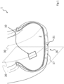
- FIG. 1 with reference number 1 it is shown a tyre (in partial perspective section) comprising a monitoring device 10 according to the present invention fixed onto the inner surface 2 of the tyre at a crown portion 16 of the tyre (i.e. the portion of the tyre at the tread band 17).
- the dashed line 30 schematically and arbitrarily indicates a boundaries line between the crown portion 16 and a sidewall of the tyre. All the figures are shown not in scale and with purely illustrative purpose.
- the monitoring device 10 comprises an electronic unit 11 comprising at least one sensor for detecting at least one of the following physical quantities: temperature, pressure, acceleration, deformation; a processing unit; a transceiver.
- the electronic unit 11 is only schematically shown in the figures.
- the monitoring device 10 comprises an accumulation device 12 electrically connected to the electronic unit to electrically supply the electronic unit, fixed to the inner surface 2 so that it is interposed between the inner surface 2 and the electronic unit 12.
- the accumulation device 12 consists of one and only one accumulator.
- the present invention also contemplates, not shown, embodiments in which the accumulation device comprises, or consists of, a plurality of distinct accumulators.
- the accumulators are placed side by side onto the inner surface and/or stacked along the direction perpendicular to the inner surface 2, to form one or more accumulator stacks.
- the plurality of accumulators comprises two and no more than two accumulators.
- the single accumulator is a primary (i.e. non-rechargeable) electric battery marketed by BrightVolt TM having a lithium metal anode, a manganese dioxide cathode and a polymeric electrolyte (classifiable among the so-called "lithium-ion polymer batteries"), with nominal voltage of 3V, a rectangular shaped plant and a maximum thickness h of about 0.5mm, according to the present invention.
- the battery has a casing made of two foldable aluminium sheets and is itself foldable without appreciable functionality loss.
- the monitoring device 10 comprises a support 14 made in a single body, wherein the electronic unit 11 is fixed to a first face 15 of the support 14 and the accumulation device 12 is fixed to a second face 18 of the support 14, opposite to the first face 15.
- the support 14 is a, flexible and inextensible, film of thickness equal to 127 ⁇ m made of polyimide (e.g. Kapton TM by DuPont ® ).
- polyester support of thickness of 125 ⁇ m are commercially available by Teijin ® with the trademark Teonex TM .
- Exemplarily the support 14, in the undeformed configuration i.e. stretched as exemplarily shown in continuous line in figures 2 and 3
- has rectangular plan shape wherein the length L3 and width L4 exceed respectively the length L1 and the width L2 of the accumulation device on both sides of about 3mm.
- the dashed lines show in a purely schematic way the peripheral portion of the support 14 folded up to the first adhesive layer 40, to wind the accumulation device 12.
- the excess of the length L3 and width L4 is such as to allow the support to completely wind also the first adhesive layer 40 and to contact the inner surface 2.
- the length L3 and width L4 of the support 14 are respectively shorter than the length L1 and the width L2 of the accumulation device on both sides (for example by about 3mm). In this way the support entirely rests on the accumulation device.
- the monitoring device 10 comprises an electric connection circuit 19 (only schematically shown in figures 2 and 3 ) for connecting the accumulation device 12 to the electronic unit 11, wherein the electric connection circuit 19 comprises at least two separate electric paths 21.
- the support 14 is provided with one or more, typically two, through openings 22 for the electric connection between the contact tabs 13 of the accumulation device 12 and the electric connection circuit 19.
- a conductive adhesive 23 e.g. Henkel 3104 WXL
- the tracks of the electric connection circuit 19 are made with a conductive ink (e.g. silver conductive ink DuPont ® 5025) directly printed on the first face 15 of the flexible substrate 14, for example with serigraphic technique.
- a conductive ink e.g. silver conductive ink DuPont ® 5025
- the electronic unit 11 comprises (not shown) at least one sensor for detecting at least one of the following physical quantities: temperature, pressure, acceleration; a processing unit and a transceiver.
- the electronic unit can comprise a pre-fabricated assembly model FXTH870911DT1 sold by NXP Semiconductors ® , comprising a processing unit and a plurality of sensors suitable for detecting all the three physical quantities: temperature, pressure and acceleration.
- This assembly also comprises an RF transceiver with transceiver frequency of 315-434 Mhz. In an exemplary embodiment, it can be used a further transceiver fixed to the flexible support separately from the aforementioned assembly, usable on a different frequency band (for example with Wifi or Bluetooth ® technology).
- the device 10 is applied onto the inner surface 2 of the tyre so that the equatorial plane 20 of the tyre intersects the monitoring device 10, more preferably intersects the electronic unit 11 (for example so that the sensor is at or near the central relief 21 of the tread 17).
- the tyre comprises a first adhesive layer 40 interposed between the accumulation device 12 and the inner surface 2 for fixing the accumulation device (and therefore the whole monitoring device) to the inner surface 2 of the tyre.
- the first adhesive layer 40 consists of a 3M TM VHB TM adhesive tape of the 4941 family, of the 4956 family or of the 5952 family.
- the monitoring device comprises a second adhesive layer 35 interposed between the support (at its second face 18) and the accumulation device 12 for fixing the support to the accumulation device.
- the second adhesive layer comprises (or consists of) a PSA acrylic adhesive (for example the 3M TM 9469, 3M TM 468, 3M TM 93430 or Nitto 5925 adhesives) or a structural adhesive (e.g. Cyberbond 2263, Henkel ® LOCTITE ® 312 TM ).
- the monitoring device comprises a protective film 36 as top layer, for example a covering nylon layer (e.g. Nylon cast film Domo TM Filmon TM CSX18), laminated with an acrylic adhesive, or a thermoplastic polyurethane layer (e.g. Covestro TM Platilon TM U 4201 U or 3M TM PPT TM 8734), thermally laminated.
- a covering nylon layer e.g. Nylon cast film Domo TM Filmon TM CSX18
- an acrylic adhesive e.g. Covestro TM Platilon TM U 4201 U or 3M TM PPT TM 8734
Landscapes
- Engineering & Computer Science (AREA)
- Mechanical Engineering (AREA)
- Measuring Fluid Pressure (AREA)
- Tires In General (AREA)
Claims (15)
- Pneumatique (1) comprenant un dispositif de surveillance (10) fixé sur une surface intérieure (2) dudit pneumatique (1) au niveau d'une partie de sommet (16) dudit pneumatique (1),dans lequel le dispositif de surveillance (10) comprend :- une unité électronique (11) comprenant au moins un capteur pour détecter au moins l'une des grandeurs physiques suivantes : la température, la pression, l'accélération, la déformation ; une unité de traitement ; un émetteur-récepteur ; et- un dispositif d'accumulation (12) relié électriquement à ladite unité électronique (11) pour alimenter électriquement ladite unité électronique (11),dans lequel ledit dispositif d'accumulation (12) est interposé entre ladite surface intérieure (2) et ladite unité électronique (11) et il est fixé à ladite surface intérieure (2),dans lequel la fixation dudit dispositif d'accumulation (12) à ladite surface intérieure (2) du pneumatique (1) s'effectue au moyen d'au moins une première couche adhésive (40) interposée entre ledit dispositif d'accumulation (12) et ladite surface intérieure (2),caractérisé en ce que ledit dispositif d'accumulation (12) a une surface plane supérieure ou égale à environ 500 mm2 et une épaisseur inférieure ou égale à environ 2,0 mm,et en ce que ladite première couche adhésive est un ruban adhésif double face comprenant (i) une mousse acrylique viscoélastique ou (ii) un substrat de matériau polymère expansé, tel que du caoutchouc EPDM ou du polyuréthane, ou (iii) au moins une couche adhésive de type acrylique d'une épaisseur égale ou supérieure à environ 0,4 mm ou (iv) leurs combinaisons, ledit ruban adhésif double face étant résistant à une contrainte de cisaillement dynamique supérieure à 50 kPa mesurée selon la norme ASTM D-1002.
- Pneumatique (1) selon la revendication 1, dans lequel ledit dispositif d'accumulation (12) a une surface plane supérieure ou égale à environ 600 mm2, dans lequel ledit dispositif d'accumulation (12) a un poids inférieur ou égal à environ 3 g, et dans lequel ledit dispositif de surveillance (10) et/ou ledit dispositif d'accumulation (12) a un poids par unité de surface plane inférieur ou égal à environ 8 × 10⁻³g/mm2.
- Pneumatique (1) selon la revendication 1 ou 2, dans lequel ledit dispositif d'accumulation (12) a une épaisseur inférieure ou égale à environ 1,0 mm.
- Pneumatique (1) selon l'une quelconque des revendications précédentes, dans lequel ledit dispositif d'accumulation (12) a une capacité de charge électrique supérieure ou égale à environ 20 mAh, dans lequel ledit dispositif d'accumulation (12) a une longueur (L1) le long d'une première direction plane supérieure ou égale à environ 15 mm, et/ou inférieure ou égale à environ 40 mm, dans lequel ledit dispositif d'accumulation (12) a une largeur (L2) le long d'une deuxième direction plane perpendiculaire à la première direction supérieure ou égale à environ 20 mm, et/ou inférieure ou égale à environ 60 mm.
- Pneumatique (1) selon l'une quelconque des revendications précédentes, dans lequel ledit dispositif d'accumulation (12) est pliable.
- Pneumatique (1) selon l'une quelconque des revendications précédentes, dans lequel ladite première couche adhésive (40) a une longueur et/ou une largeur supérieure à, respectivement, une longueur et/ou une largeur du dispositif d'accumulation (12) , dans lequel la longueur et/ou la largeur de la première couche adhésive (40) dépasse respectivement la longueur et/ou la largeur du dispositif d'accumulation (12) des deux côtés sur un dépassement global d'au moins environ 0,5 mm, et dans lequel la première couche adhésive (40) est résistante aux températures de fonctionnement allant d'environ -40°C jusqu'à environ 160°C.
- Pneumatique (1) selon l'une quelconque des revendications précédentes, dans lequel une épaisseur de la première couche adhésive (40), y compris toutes les couches adhésives déposées sur ses surfaces, est comprise entre environ 0,4 et environ 2,4 mm.
- Pneumatique (1) selon l'une quelconque des revendications précédentes, dans lequel le dispositif de surveillance (10) comprend un support (14) réalisé en un seul corps, dans lequel ladite unité électronique (11) est fixée sur une première face (15) dudit support (14) et ledit dispositif d'accumulation (12) est fixé sur une deuxième face (18) dudit support (14), opposée à la première face (15).
- Pneumatique (1) selon la revendication 8, dans lequel ledit support (14) est flexible, c'est-à-dire qu'il est réalisé en un matériau qui, s'il est utilisé pour la confection d'une feuille de forme carrée de côté sensiblement supérieur à une extension circonférentielle d'une surface d'entrée ou de sortie d'une zone d'empreinte dudit pneumatique (1) et d'épaisseur égale audit support (14), permet à la feuille de se conformer - à température ambiante - à une surface cylindrique de rayon inférieur au rayon de courbure normal dudit pneumatique (1) gonflé à sa pression nominale sans se casser ni subir de déformation permanente, dans lequel ledit support (14) est inextensible, c'est-à-dire qu'il a une épaisseur comprise entre environ 10 µm et environ 400 µm et est réalisé avec un matériau ayant un module d'élasticité en traction supérieur à 0,1 GPa à 23°C, dans lequel ledit support flexible (14) est un film d'un matériau élastomère ou thermoplastique choisi dans le groupe suivant : le nylon, le PET, le PEN, le polyimide, l'EPDM, les polymères diéniques et les résines de polyuréthane, ou il est un substrat en papier, ou une feuille mince en résine époxy ou en silicium ou en autre semi-conducteur.
- Pneumatique (1) selon la revendication 8 ou 9, dans lequel ledit support (14) présente une surface plane supérieure ou égale à 70% de ladite surface plane du dispositif d'accumulation (12).
- Pneumatique (1) selon l'une quelconque des revendications 8 à 10, dans lequel ledit support (14) présente une surface plane supérieure ou égale à 110 % de ladite surface plane du dispositif d'accumulation (12), et/ou inférieure ou égale à 150 % de ladite surface plane du dispositif d'accumulation (12).
- Pneumatique (1) selon l'une quelconque des revendications 8 à 11, dans lequel le dispositif de surveillance (10) comprend un circuit de connexion électrique (19) pour connecter le dispositif d'accumulation (12) à ladite unité électronique (11), dans lequel le circuit de connexion électrique (19) est fixé sur ladite première face (15) dudit support (14), dans lequel le circuit de connexion électrique (19) comprend au moins deux chemins électriques séparés (21), dans lequel le support (14) est pourvu d'une ou plusieurs ouvertures traversantes (22) le long d'une direction perpendiculaire à ladite surface intérieure (2), dans lequel des contacts électriques (13) du dispositif d'accumulation (12) sont connectés électriquement audit circuit de connexion électrique (19) à travers ladite une ou plusieurs ouvertures traversantes (22), et dans lequel un adhésif conducteur (23) passe à travers lesdites une ou plusieurs ouvertures traversantes (22) pour établir ladite connexion électrique.
- Pneumatique (1) selon la revendication 6 et l'une quelconque des revendications 8 à 12, dans lequel le dispositif de surveillance (10) comprend une deuxième couche adhésive (35) interposée entre ledit support (14) et ledit dispositif d'accumulation (12) pour fixer ledit support (14) audit dispositif d'accumulation (12), dans lequel ladite deuxième couche adhésive (35) comprend un adhésif acrylique sensible à la pression.
- Pneumatique (1) selon l'une quelconque des revendications précédentes, dans lequel ledit au moins un capteur est adapté pour détecter au moins deux des grandeurs physiques suivantes : la température, la pression, la déformation, l'accélération, et dans lequel un plan équatorial (20) du pneumatique (1) traverse ledit dispositif de surveillance (10).
- Pneumatique (1) selon l'une quelconque des revendications précédentes, dans lequel ledit dispositif d'accumulation (12) comprend, ou est constitué par, un ou plusieurs accumulateurs distincts, dans lequel ledit dispositif d'accumulation (12) est constitué par un et un seul accumulateur, ou dans lequel ledit dispositif d'accumulation (12) comprend, ou est constitué par, une pluralité d'accumulateurs distincts agencés côte à côte sur la surface intérieure et/ou empilés le long d'une direction perpendiculaire à ladite surface intérieure (2) pour former un ou plusieurs empilements d'accumulateurs.
Applications Claiming Priority (2)
| Application Number | Priority Date | Filing Date | Title |
|---|---|---|---|
| IT201900010899 | 2019-07-04 | ||
| PCT/IT2020/050156 WO2021001862A1 (fr) | 2019-07-04 | 2020-06-24 | Pneu comprenant un dispositif de surveillance |
Publications (3)
| Publication Number | Publication Date |
|---|---|
| EP3994014A1 EP3994014A1 (fr) | 2022-05-11 |
| EP3994014C0 EP3994014C0 (fr) | 2023-08-16 |
| EP3994014B1 true EP3994014B1 (fr) | 2023-08-16 |
Family
ID=68343360
Family Applications (1)
| Application Number | Title | Priority Date | Filing Date |
|---|---|---|---|
| EP20740425.2A Active EP3994014B1 (fr) | 2019-07-04 | 2020-06-24 | Pneu comprenant un dispositif de surveillance |
Country Status (3)
| Country | Link |
|---|---|
| EP (1) | EP3994014B1 (fr) |
| CN (1) | CN114072294A (fr) |
| WO (1) | WO2021001862A1 (fr) |
Family Cites Families (21)
| Publication number | Priority date | Publication date | Assignee | Title |
|---|---|---|---|---|
| US5971046A (en) * | 1997-09-17 | 1999-10-26 | Bridgestone/Firestone, Inc. | Method and apparatus for bonding an active tag to a patch and a tire |
| US6576365B1 (en) * | 1999-12-06 | 2003-06-10 | E.C.R. - Electro Chemical Research Ltd. | Ultra-thin electrochemical energy storage devices |
| ES2292984T3 (es) * | 2003-06-12 | 2008-03-16 | Pirelli Tyre S.P.A. | Neumatico equipado con un dispositivo de monitorizacion, y procedimiento para instalar el dispositivo sobre la superficie interior del neumatico. |
| US20050076982A1 (en) * | 2003-10-09 | 2005-04-14 | Metcalf Arthur Richard | Post patch assembly for mounting devices in a tire interior |
| JP2006015884A (ja) * | 2004-07-02 | 2006-01-19 | Yokohama Rubber Co Ltd:The | タイヤ情報送信装置、タイヤ情報取得システムおよびタイヤ・ホイール組立体 |
| JPWO2007072730A1 (ja) * | 2005-12-19 | 2009-05-28 | パナソニック株式会社 | 扁平形電池 |
| ATE450385T1 (de) * | 2006-07-28 | 2009-12-15 | Pirelli | Rad für fahrzeuge |
| DE102007014097A1 (de) * | 2007-03-21 | 2008-09-25 | Continental Teves Ag & Co. Ohg | Reifenmodul |
| JP5546808B2 (ja) * | 2009-07-03 | 2014-07-09 | 日立マクセル株式会社 | 扁平形電池の取付方法及び回転部分に取り付けられる装置 |
| BR112013016890A8 (pt) * | 2010-12-30 | 2018-01-02 | Michelin & Cie | Sistema a base de piezoeléctrico e método para determinação de carga de pneu |
| ITMI20112427A1 (it) * | 2011-12-29 | 2013-06-30 | Pirelli | Dispositivo di monitoraggio per pneumatici per ruote di veicoli, pneumatico per ruote di veicoli provvisto di detto dispositivo di monitoraggio, e metodo per installare un'unita' elettronica in detto pneumatico |
| ITMI20131335A1 (it) * | 2013-08-05 | 2015-02-06 | Pirelli | Dispositivo di monitoraggio per pneumatici per ruote di veicoli, pneumatico provvisto di detto dispositivo di monitoraggio e metodo per installare un' unita' elettronica in un pneumatico |
| BR112016022147A2 (pt) * | 2014-03-28 | 2017-08-15 | Pirelli | Dispositivo de sensor de pneu, e, pneu de veículo |
| HRP20221548T1 (hr) * | 2014-09-17 | 2023-03-03 | STE Industries s.r.l. | Uređaj za prijenos i postupak bežičnog prijenosa mjerenih parametara |
| WO2017155035A1 (fr) * | 2016-03-09 | 2017-09-14 | 日立マクセル株式会社 | Système de détection de pression de pneumatique |
| CN106080056A (zh) * | 2016-08-22 | 2016-11-09 | 万通智控科技股份有限公司 | 一种粘附外胎内壁的胎压监测装置 |
| CN109715417B (zh) * | 2016-10-04 | 2021-11-23 | 倍耐力轮胎股份公司 | 用于将电子单元固定到轮胎的装置和包括电子单元的轮胎 |
| CN106450366A (zh) * | 2016-10-19 | 2017-02-22 | 上海空间电源研究所 | 热电池用超薄型单体电池及其制备方法 |
| DE102017104732A1 (de) * | 2017-03-07 | 2018-09-13 | Infineon Technologies Ag | Reifensensorvorrichtung und Verfahren |
| DE102017110570A1 (de) * | 2017-04-28 | 2018-10-31 | Huf Hülsbeck & Fürst Gmbh & Co. Kg | Reifendrucküberwachungseinheit |
| CN108899986A (zh) * | 2018-09-03 | 2018-11-27 | 惠州赛尔雷新能源科技有限公司 | 一种无限容量超薄锂电池 |
-
2020
- 2020-06-24 WO PCT/IT2020/050156 patent/WO2021001862A1/fr unknown
- 2020-06-24 CN CN202080045436.6A patent/CN114072294A/zh active Pending
- 2020-06-24 EP EP20740425.2A patent/EP3994014B1/fr active Active
Also Published As
| Publication number | Publication date |
|---|---|
| EP3994014A1 (fr) | 2022-05-11 |
| WO2021001862A1 (fr) | 2021-01-07 |
| CN114072294A (zh) | 2022-02-18 |
| EP3994014C0 (fr) | 2023-08-16 |
Similar Documents
| Publication | Publication Date | Title |
|---|---|---|
| RU2762050C1 (ru) | Шина, содержащая устройство мониторинга | |
| JP4942984B2 (ja) | 回転するタイヤの機械エネルギーから電力を発生するシステム及び方法 | |
| KR101946001B1 (ko) | 타이어 공기압 모니터링 시스템 | |
| CN106427419A (zh) | 车辆轮胎内的电能产生 | |
| CN114761260B (zh) | 包括监测装置的摩托车轮胎 | |
| EP3898291B1 (fr) | Pneumatique avec dispositif de surveillance | |
| CN113165453A (zh) | 具有监测装置的轮胎 | |
| EP3994014B1 (fr) | Pneu comprenant un dispositif de surveillance | |
| JP2007163230A (ja) | タイヤ空気圧センサおよびタイヤ空気圧監視装置 | |
| RU2773058C1 (ru) | Шина, содержащая устройство мониторинга | |
| RU2801670C2 (ru) | Шина с устройством мониторинга | |
| CN114179570A (zh) | 压电轮胎 | |
| WO2023228224A1 (fr) | Pneumatique avec dispositif de contrôle | |
| LU501377B1 (en) | Compression Device for Accurate Compression Load Management in a Battery Pack | |
| WO2023110774A1 (fr) | Cellule de détection de pression pour une détection de pression précise dans un bloc-batterie |
Legal Events
| Date | Code | Title | Description |
|---|---|---|---|
| STAA | Information on the status of an ep patent application or granted ep patent |
Free format text: STATUS: UNKNOWN |
|
| STAA | Information on the status of an ep patent application or granted ep patent |
Free format text: STATUS: THE INTERNATIONAL PUBLICATION HAS BEEN MADE |
|
| PUAI | Public reference made under article 153(3) epc to a published international application that has entered the european phase |
Free format text: ORIGINAL CODE: 0009012 |
|
| STAA | Information on the status of an ep patent application or granted ep patent |
Free format text: STATUS: REQUEST FOR EXAMINATION WAS MADE |
|
| 17P | Request for examination filed |
Effective date: 20211227 |
|
| AK | Designated contracting states |
Kind code of ref document: A1 Designated state(s): AL AT BE BG CH CY CZ DE DK EE ES FI FR GB GR HR HU IE IS IT LI LT LU LV MC MK MT NL NO PL PT RO RS SE SI SK SM TR |
|
| DAV | Request for validation of the european patent (deleted) | ||
| DAX | Request for extension of the european patent (deleted) | ||
| GRAP | Despatch of communication of intention to grant a patent |
Free format text: ORIGINAL CODE: EPIDOSNIGR1 |
|
| STAA | Information on the status of an ep patent application or granted ep patent |
Free format text: STATUS: GRANT OF PATENT IS INTENDED |
|
| INTG | Intention to grant announced |
Effective date: 20230503 |
|
| GRAS | Grant fee paid |
Free format text: ORIGINAL CODE: EPIDOSNIGR3 |
|
| GRAA | (expected) grant |
Free format text: ORIGINAL CODE: 0009210 |
|
| STAA | Information on the status of an ep patent application or granted ep patent |
Free format text: STATUS: THE PATENT HAS BEEN GRANTED |
|
| AK | Designated contracting states |
Kind code of ref document: B1 Designated state(s): AL AT BE BG CH CY CZ DE DK EE ES FI FR GB GR HR HU IE IS IT LI LT LU LV MC MK MT NL NO PL PT RO RS SE SI SK SM TR |
|
| REG | Reference to a national code |
Ref country code: CH Ref legal event code: EP |
|
| REG | Reference to a national code |
Ref country code: DE Ref legal event code: R096 Ref document number: 602020015883 Country of ref document: DE |
|
| REG | Reference to a national code |
Ref country code: IE Ref legal event code: FG4D |
|
| U01 | Request for unitary effect filed |
Effective date: 20230816 |
|
| U07 | Unitary effect registered |
Designated state(s): AT BE BG DE DK EE FI FR IT LT LU LV MT NL PT SE SI Effective date: 20230822 |
|
| PG25 | Lapsed in a contracting state [announced via postgrant information from national office to epo] |
Ref country code: GR Free format text: LAPSE BECAUSE OF FAILURE TO SUBMIT A TRANSLATION OF THE DESCRIPTION OR TO PAY THE FEE WITHIN THE PRESCRIBED TIME-LIMIT Effective date: 20231117 |
|
| PG25 | Lapsed in a contracting state [announced via postgrant information from national office to epo] |
Ref country code: IS Free format text: LAPSE BECAUSE OF FAILURE TO SUBMIT A TRANSLATION OF THE DESCRIPTION OR TO PAY THE FEE WITHIN THE PRESCRIBED TIME-LIMIT Effective date: 20231216 |
|
| PG25 | Lapsed in a contracting state [announced via postgrant information from national office to epo] |
Ref country code: RS Free format text: LAPSE BECAUSE OF FAILURE TO SUBMIT A TRANSLATION OF THE DESCRIPTION OR TO PAY THE FEE WITHIN THE PRESCRIBED TIME-LIMIT Effective date: 20230816 Ref country code: NO Free format text: LAPSE BECAUSE OF FAILURE TO SUBMIT A TRANSLATION OF THE DESCRIPTION OR TO PAY THE FEE WITHIN THE PRESCRIBED TIME-LIMIT Effective date: 20231116 Ref country code: IS Free format text: LAPSE BECAUSE OF FAILURE TO SUBMIT A TRANSLATION OF THE DESCRIPTION OR TO PAY THE FEE WITHIN THE PRESCRIBED TIME-LIMIT Effective date: 20231216 Ref country code: HR Free format text: LAPSE BECAUSE OF FAILURE TO SUBMIT A TRANSLATION OF THE DESCRIPTION OR TO PAY THE FEE WITHIN THE PRESCRIBED TIME-LIMIT Effective date: 20230816 Ref country code: GR Free format text: LAPSE BECAUSE OF FAILURE TO SUBMIT A TRANSLATION OF THE DESCRIPTION OR TO PAY THE FEE WITHIN THE PRESCRIBED TIME-LIMIT Effective date: 20231117 |
|
| PG25 | Lapsed in a contracting state [announced via postgrant information from national office to epo] |
Ref country code: PL Free format text: LAPSE BECAUSE OF FAILURE TO SUBMIT A TRANSLATION OF THE DESCRIPTION OR TO PAY THE FEE WITHIN THE PRESCRIBED TIME-LIMIT Effective date: 20230816 |
|
| PG25 | Lapsed in a contracting state [announced via postgrant information from national office to epo] |
Ref country code: ES Free format text: LAPSE BECAUSE OF FAILURE TO SUBMIT A TRANSLATION OF THE DESCRIPTION OR TO PAY THE FEE WITHIN THE PRESCRIBED TIME-LIMIT Effective date: 20230816 |
|
| PG25 | Lapsed in a contracting state [announced via postgrant information from national office to epo] |
Ref country code: SM Free format text: LAPSE BECAUSE OF FAILURE TO SUBMIT A TRANSLATION OF THE DESCRIPTION OR TO PAY THE FEE WITHIN THE PRESCRIBED TIME-LIMIT Effective date: 20230816 Ref country code: RO Free format text: LAPSE BECAUSE OF FAILURE TO SUBMIT A TRANSLATION OF THE DESCRIPTION OR TO PAY THE FEE WITHIN THE PRESCRIBED TIME-LIMIT Effective date: 20230816 Ref country code: ES Free format text: LAPSE BECAUSE OF FAILURE TO SUBMIT A TRANSLATION OF THE DESCRIPTION OR TO PAY THE FEE WITHIN THE PRESCRIBED TIME-LIMIT Effective date: 20230816 Ref country code: CZ Free format text: LAPSE BECAUSE OF FAILURE TO SUBMIT A TRANSLATION OF THE DESCRIPTION OR TO PAY THE FEE WITHIN THE PRESCRIBED TIME-LIMIT Effective date: 20230816 Ref country code: SK Free format text: LAPSE BECAUSE OF FAILURE TO SUBMIT A TRANSLATION OF THE DESCRIPTION OR TO PAY THE FEE WITHIN THE PRESCRIBED TIME-LIMIT Effective date: 20230816 |