EP3992792A1 - Procédé d'attribution de ressources, dispositif de stockage et système de stockage - Google Patents
Procédé d'attribution de ressources, dispositif de stockage et système de stockage Download PDFInfo
- Publication number
- EP3992792A1 EP3992792A1 EP20840105.9A EP20840105A EP3992792A1 EP 3992792 A1 EP3992792 A1 EP 3992792A1 EP 20840105 A EP20840105 A EP 20840105A EP 3992792 A1 EP3992792 A1 EP 3992792A1
- Authority
- EP
- European Patent Office
- Prior art keywords
- address segment
- allocated
- segment set
- resources
- address
- Prior art date
- Legal status (The legal status is an assumption and is not a legal conclusion. Google has not performed a legal analysis and makes no representation as to the accuracy of the status listed.)
- Pending
Links
Images


Classifications
-
- G—PHYSICS
- G06—COMPUTING; CALCULATING OR COUNTING
- G06F—ELECTRIC DIGITAL DATA PROCESSING
- G06F3/00—Input arrangements for transferring data to be processed into a form capable of being handled by the computer; Output arrangements for transferring data from processing unit to output unit, e.g. interface arrangements
- G06F3/06—Digital input from, or digital output to, record carriers, e.g. RAID, emulated record carriers or networked record carriers
- G06F3/0601—Interfaces specially adapted for storage systems
- G06F3/0628—Interfaces specially adapted for storage systems making use of a particular technique
- G06F3/0638—Organizing or formatting or addressing of data
- G06F3/064—Management of blocks
-
- G—PHYSICS
- G06—COMPUTING; CALCULATING OR COUNTING
- G06F—ELECTRIC DIGITAL DATA PROCESSING
- G06F3/00—Input arrangements for transferring data to be processed into a form capable of being handled by the computer; Output arrangements for transferring data from processing unit to output unit, e.g. interface arrangements
- G06F3/06—Digital input from, or digital output to, record carriers, e.g. RAID, emulated record carriers or networked record carriers
- G06F3/0601—Interfaces specially adapted for storage systems
- G06F3/0668—Interfaces specially adapted for storage systems adopting a particular infrastructure
- G06F3/0671—In-line storage system
- G06F3/0683—Plurality of storage devices
-
- G—PHYSICS
- G06—COMPUTING; CALCULATING OR COUNTING
- G06F—ELECTRIC DIGITAL DATA PROCESSING
- G06F12/00—Accessing, addressing or allocating within memory systems or architectures
- G06F12/02—Addressing or allocation; Relocation
- G06F12/0223—User address space allocation, e.g. contiguous or non contiguous base addressing
- G06F12/0284—Multiple user address space allocation, e.g. using different base addresses
-
- G—PHYSICS
- G06—COMPUTING; CALCULATING OR COUNTING
- G06F—ELECTRIC DIGITAL DATA PROCESSING
- G06F3/00—Input arrangements for transferring data to be processed into a form capable of being handled by the computer; Output arrangements for transferring data from processing unit to output unit, e.g. interface arrangements
- G06F3/06—Digital input from, or digital output to, record carriers, e.g. RAID, emulated record carriers or networked record carriers
- G06F3/0601—Interfaces specially adapted for storage systems
- G06F3/0602—Interfaces specially adapted for storage systems specifically adapted to achieve a particular effect
- G06F3/0604—Improving or facilitating administration, e.g. storage management
-
- G—PHYSICS
- G06—COMPUTING; CALCULATING OR COUNTING
- G06F—ELECTRIC DIGITAL DATA PROCESSING
- G06F3/00—Input arrangements for transferring data to be processed into a form capable of being handled by the computer; Output arrangements for transferring data from processing unit to output unit, e.g. interface arrangements
- G06F3/06—Digital input from, or digital output to, record carriers, e.g. RAID, emulated record carriers or networked record carriers
- G06F3/0601—Interfaces specially adapted for storage systems
- G06F3/0602—Interfaces specially adapted for storage systems specifically adapted to achieve a particular effect
- G06F3/061—Improving I/O performance
-
- G—PHYSICS
- G06—COMPUTING; CALCULATING OR COUNTING
- G06F—ELECTRIC DIGITAL DATA PROCESSING
- G06F3/00—Input arrangements for transferring data to be processed into a form capable of being handled by the computer; Output arrangements for transferring data from processing unit to output unit, e.g. interface arrangements
- G06F3/06—Digital input from, or digital output to, record carriers, e.g. RAID, emulated record carriers or networked record carriers
- G06F3/0601—Interfaces specially adapted for storage systems
- G06F3/0628—Interfaces specially adapted for storage systems making use of a particular technique
- G06F3/0629—Configuration or reconfiguration of storage systems
- G06F3/0631—Configuration or reconfiguration of storage systems by allocating resources to storage systems
-
- G—PHYSICS
- G06—COMPUTING; CALCULATING OR COUNTING
- G06F—ELECTRIC DIGITAL DATA PROCESSING
- G06F3/00—Input arrangements for transferring data to be processed into a form capable of being handled by the computer; Output arrangements for transferring data from processing unit to output unit, e.g. interface arrangements
- G06F3/06—Digital input from, or digital output to, record carriers, e.g. RAID, emulated record carriers or networked record carriers
- G06F3/0601—Interfaces specially adapted for storage systems
- G06F3/0628—Interfaces specially adapted for storage systems making use of a particular technique
- G06F3/0638—Organizing or formatting or addressing of data
- G06F3/0644—Management of space entities, e.g. partitions, extents, pools
-
- G—PHYSICS
- G06—COMPUTING; CALCULATING OR COUNTING
- G06F—ELECTRIC DIGITAL DATA PROCESSING
- G06F3/00—Input arrangements for transferring data to be processed into a form capable of being handled by the computer; Output arrangements for transferring data from processing unit to output unit, e.g. interface arrangements
- G06F3/06—Digital input from, or digital output to, record carriers, e.g. RAID, emulated record carriers or networked record carriers
- G06F3/0601—Interfaces specially adapted for storage systems
- G06F3/0628—Interfaces specially adapted for storage systems making use of a particular technique
- G06F3/0655—Vertical data movement, i.e. input-output transfer; data movement between one or more hosts and one or more storage devices
- G06F3/0658—Controller construction arrangements
-
- G—PHYSICS
- G06—COMPUTING; CALCULATING OR COUNTING
- G06F—ELECTRIC DIGITAL DATA PROCESSING
- G06F3/00—Input arrangements for transferring data to be processed into a form capable of being handled by the computer; Output arrangements for transferring data from processing unit to output unit, e.g. interface arrangements
- G06F3/06—Digital input from, or digital output to, record carriers, e.g. RAID, emulated record carriers or networked record carriers
- G06F3/0601—Interfaces specially adapted for storage systems
- G06F3/0628—Interfaces specially adapted for storage systems making use of a particular technique
- G06F3/0662—Virtualisation aspects
- G06F3/0664—Virtualisation aspects at device level, e.g. emulation of a storage device or system
-
- G—PHYSICS
- G06—COMPUTING; CALCULATING OR COUNTING
- G06F—ELECTRIC DIGITAL DATA PROCESSING
- G06F3/00—Input arrangements for transferring data to be processed into a form capable of being handled by the computer; Output arrangements for transferring data from processing unit to output unit, e.g. interface arrangements
- G06F3/06—Digital input from, or digital output to, record carriers, e.g. RAID, emulated record carriers or networked record carriers
- G06F3/0601—Interfaces specially adapted for storage systems
- G06F3/0668—Interfaces specially adapted for storage systems adopting a particular infrastructure
- G06F3/067—Distributed or networked storage systems, e.g. storage area networks [SAN], network attached storage [NAS]
-
- G—PHYSICS
- G06—COMPUTING; CALCULATING OR COUNTING
- G06F—ELECTRIC DIGITAL DATA PROCESSING
- G06F9/00—Arrangements for program control, e.g. control units
- G06F9/06—Arrangements for program control, e.g. control units using stored programs, i.e. using an internal store of processing equipment to receive or retain programs
- G06F9/46—Multiprogramming arrangements
- G06F9/50—Allocation of resources, e.g. of the central processing unit [CPU]
- G06F9/5005—Allocation of resources, e.g. of the central processing unit [CPU] to service a request
- G06F9/5027—Allocation of resources, e.g. of the central processing unit [CPU] to service a request the resource being a machine, e.g. CPUs, Servers, Terminals
-
- G—PHYSICS
- G06—COMPUTING; CALCULATING OR COUNTING
- G06F—ELECTRIC DIGITAL DATA PROCESSING
- G06F9/00—Arrangements for program control, e.g. control units
- G06F9/06—Arrangements for program control, e.g. control units using stored programs, i.e. using an internal store of processing equipment to receive or retain programs
- G06F9/46—Multiprogramming arrangements
- G06F9/50—Allocation of resources, e.g. of the central processing unit [CPU]
- G06F9/5061—Partitioning or combining of resources
-
- G—PHYSICS
- G06—COMPUTING; CALCULATING OR COUNTING
- G06F—ELECTRIC DIGITAL DATA PROCESSING
- G06F2209/00—Indexing scheme relating to G06F9/00
- G06F2209/50—Indexing scheme relating to G06F9/50
- G06F2209/5011—Pool
Definitions
- This application relates to the storage field, and more specifically, to a resource allocation method, a storage device, and a storage system.
- a current storage node usually has a plurality of controllers, and each controller includes a plurality of processors.
- the plurality of processors When the storage node executes a service request, the plurality of processors usually need to process in parallel a plurality of sub-requests obtained by splitting the service request. Because these sub-requests are associated with each other, forwarding and data interaction of the sub-requests between the plurality of processors are involved, and bandwidth resources between the processors are occupied.
- This application mainly aims to resolve a problem of how to save bandwidth resources between processors.
- a storage device including a disk enclosure and a plurality of controllers.
- Each controller includes a plurality of processors, each processor includes a plurality of processor cores, the plurality of controllers are separately coupled to the disk enclosure, and the disk enclosure includes a plurality of hard disks.
- the plurality of processors are configured to provide computing resources.
- Computing resources allocated to different address segment sets are from different processors, or computing resources allocated to different address segment sets are from different processor cores.
- the LUNs are provided by the storage device for a user, and addresses corresponding to the LUNs are classified into several logical block address LBA intervals, each address segment is one LBA interval.
- computing resources used to process different address segment sets are from different processors. Because a data access request used to access an address segment is executed by an allocated processor, and different CPUs are allocated to different address segment sets, a data access request can be prevented from being forwarded between a plurality of processors, and fewer bandwidth resources between the processor need to be used. In the other implementation, computing resources used to process different address segment sets are from different processor cores.
- a data access request used to access an address segment is executed by an allocated processor core, compared with the foregoing implementation, data access requests for different address segment sets are isolated at a finer granularity, and the data access requests are executed in series by processor cores allocated to the data access requests, thereby reducing mutually exclusive operations, and implementing a lock-free design.
- each processor has a memory
- the computing resources further include a plurality of memories included in the plurality of processors, and one memory is allocated to one address segment set. Different memories are allocated to different address segment sets.
- a memory allocated to each address segment set is a local memory of a processor that is allocated to the address segment set.
- a processor has a memory, which is also referred to as a local memory of the processor.
- the local memory is usually integrated into a component together with the processor, or is directly or indirectly coupled to the processor.
- the local memory of the processor that is allocated to the address segment set may be preferentially allocated to the address segment set. Using the nearby local memory of the processor can avoid cross-CPU data transmission.
- the storage device further includes network resources, the network resources are provided by a plurality of connections between the plurality of controllers and the disk enclosure, and some of the network resources are allocated to each address segment set. Different connections are allocated to different address segment sets.
- the storage space includes a plurality of chunk groups, the plurality of chunk groups provide storage resources, and some of the storage resources are allocated to each address segment set. Different address segment sets are allocated to different chunk groups.
- the storage device further includes a front-end interface card, the plurality of controllers are separately coupled to the front-end interface card, the front-end interface card stores a mapping table, and the mapping table is used to indicate a mapping relationship between each address segment set and allocated computing resources.
- mapping table is further used to indicate a mapping relationship between each address segment set and allocated network resources.
- mapping table is further used to indicate a mapping relationship between each address segment set and allocated hard disk resources.
- mapping table records a mapping relationship between each virtual node and computing resources allocated to an address segment set to which the virtual node is mapped.
- the mapping table further records a mapping relationship between each virtual node and network resources allocated to an address segment set to which the virtual node is mapped.
- the mapping table further records a mapping relationship between each virtual node and hard disk resources allocated to an address segment set to which the virtual node is mapped.
- the storage device further includes a newly added controller, the newly added controller includes a processor, and the newly added controller is coupled to the disk enclosure.
- the newly added controller is configured to: use the processor included in the newly added controller as a computing resource, allocate the processor to a first address segment in an address segment set, and release an allocation relationship between the first address segment and computing resources allocated to the address segment set.
- this implementation can more slightly change a mapping relationship between an address segment and an original resource.
- a resource allocation method is provided. The method is applied to the storage device provided in any one of the implementations of the first aspect, and is used to implement functions of the storage device.
- a computer program product is provided.
- the storage device is enabled to perform the resource allocation method in the second aspect.
- a computer-readable storage medium stores an instruction, and when the instruction is run on a storage device, the storage device is enabled to perform the resource allocation method in the second aspect.
- a storage node includes a plurality of controllers.
- a plurality of virtual nodes are created in the storage node, computing resources are pre-allocated to the virtual nodes, and the computing resources are from a computing resource pool.
- Several data access requests received by the storage node are routed to the plurality of virtual nodes. Each data access request corresponds to one virtual node, and each data access request is executed by using a computing resource allocated to a corresponding virtual node.
- the plurality of controllers are configured to provide computing resources for the computing resource pool, and the computing resources are provided by a plurality of processors included in the plurality of controllers.
- One processor is allocated to one virtual node, and different processors are allocated to different virtual nodes.
- one processor is allocated to a plurality of virtual nodes, and different processor cores are allocated to different virtual nodes.
- each processor has a memory
- the computing resource pool further includes a plurality of memories included in the plurality of processors.
- One memory is allocated to one virtual node, and different memories are allocated to different virtual nodes.
- a memory allocated to each virtual node is a local memory of a processor that is allocated to the virtual node.
- the plurality of controllers are separately coupled to a disk enclosure, and the disk enclosure includes a plurality of hard disks.
- Network resources are further pre-allocated to the virtual nodes, the network resources are from a network resource pool, and the network resource pool is provided by connections between the plurality of controllers and the disk enclosure.
- Each virtual node corresponds to one or more connections, and different connections are allocated to different virtual nodes.
- hard disk resources are further pre-allocated to the virtual nodes, the hard disk resources are from a hard disk resource pool, and the hard disk resource pool is provided by the plurality of hard disks.
- Each virtual node corresponds to one or more chunk groups, and different chunk groups are allocated to different virtual nodes.
- the storage node further includes a front-end interface card, the front-end interface card is coupled to the plurality of controllers, and the front-end interface card stores a correspondence between each virtual node and allocated computing resources, and/or a correspondence between each virtual node and allocated network resources, and/or a correspondence between each virtual node and allocated hard disk resources.
- the front-end interface card is further configured to: receive a first data access request sent by a host, where the data access request includes a virtual address; determine, based on the virtual address, a first virtual node corresponding to the first data access request; determine, based on the stored correspondence, a first processor allocated to the first virtual node; and forward the first data access request to the first processor.
- the first processor is configured to process the first data access request.
- data or metadata used when the first data access request is processed is temporarily stored in a first memory corresponding to the first virtual node.
- the first processor is further configured to: send, to the disk enclosure through a first connection allocated to the first virtual node, data that the first data access request requests to write, so that the data is written into a first chunk group allocated to the first virtual node, or write, into the first memory through the first connection, data that the first data access request requests to read.
- another resource management method is provided.
- the method is applied to a storage node, the storage node includes a plurality of controllers, and each controller includes a plurality of processors.
- the method includes: creating a plurality of virtual nodes; and allocating computing resources to the virtual nodes.
- Several data access requests received by the storage node are routed to the plurality of virtual nodes, each data access request corresponds to one virtual node, and each data access request is executed by using a computing resource allocated to a corresponding virtual node.
- Each of the plurality of processors is allocate to one of the plurality of virtual nodes, and different processors are allocated to different nodes.
- the computing resources are from a computing resource pool, the computing resources in the computing resource pool are provided by the plurality of controllers, and the computing resource pool includes the plurality of processors.
- the creating a plurality of virtual nodes includes: creating the plurality of virtual nodes based on a quantity of processors included in the storage node.
- a quantity of the plurality of virtual nodes is less than or equal to a quantity of processors included in the plurality of storage nodes.
- a computer program product is provided.
- the controller is enabled to perform the resource allocation method in the sixth aspect.
- a computer-readable storage medium stores an instruction, and when the instruction is run on a controller of a storage node, the controller is enabled to perform the resource allocation method in the seventh aspect.
- a storage system including a host and a plurality of storage nodes.
- Storage space provided by the plurality of storage nodes is classified into several address segment sets, and each address segment set includes one or more address segments.
- the host is configured to: generate a data access request, where the data access request includes a virtual address; determine, based on the virtual address, an address segment set corresponding to the target data, where the address segment set indicates a target storage node that processes the data access request, and the target storage node is one of the plurality of storage nodes; and send the data access request to the target storage node, so that the target storage node processes the data access request by using a resource that is pre-allocated to the address segment set corresponding to the target data. Processing performed by the target storage node on the data access request is similar to that in the first aspect.
- a data processing method may be applied to the storage device provided in the first aspect, or may be applied to the storage node provided in the fifth aspect, or may be applied to the storage system.
- the method includes: receiving a data access request, where the request carries a virtual address; uniquely determining an address segment set or a virtual node based on the virtual address, where computing resources are allocated to the address segment set (or the virtual node); and processing the data access request by using the allocated computing resources.
- a network resource and a hard disk resource are further allocated to the address segment set (or the virtual node), and the method further includes: reading data from the hard disk resource by using the allocated network resource, or storing to-be-written data in the hard disk resource.
- different processors are allocated to data access requests for accessing different address segment sets, so that request or data forwarding between processors can be avoided to some extent, thereby saving bandwidth resources between the processors.
- different processor cores are allocated to data access requests for accessing different address segment sets, so that request or data forwarding between processor cores can be further avoided.
- resources allocated to data access requests for accessing different address segment sets are independent of each other, so that fewer mutually exclusive operations can be performed, and a lock-free design can be implemented.
- a capacity expansion method of a storage node includes a first controller, and the first controller includes a plurality of processors.
- a second controller is added to the storage node, a second virtual node set is created.
- the second controller includes a plurality of processors, and the second virtual node set includes a plurality of second virtual nodes.
- the first virtual node set includes a plurality of first virtual nodes, and several data access requests received by the storage node are routed to the plurality of first virtual nodes.
- the plurality of processors included in the second controller are added to a computing resource pool, and the computing resource pool includes the plurality of processors provided by the first controller.
- Computing resources are allocated to the plurality of second virtual nodes, and the allocated computing resources are from the computing resource pool.
- One processor is allocated to each second virtual node, and different processors are allocated to different second virtual nodes.
- a storage node configured to implement the method provided in the eleventh aspect.
- the capacity expansion method of the storage node provided in the eleventh aspect of this application and the storage node provided in the twelfth aspect of this application several virtual nodes are created, and resources are allocated to the virtual nodes.
- a quantity of computing resources of the storage node increases, a quantity of virtual nodes may correspondingly increase, newly added computing resources are allocated to newly added virtual nodes, and some of data access requests routed to the original virtual nodes may be reallocated to the newly added virtual nodes.
- a processing capability of the entire storage node also increases. Therefore, when a quantity of hardware resources increases, a processing capability of the storage node also linearly increases.
- This application mainly aims to resolve a problem of how to save bandwidth resources between processors.
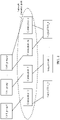
- FIG. 1 is a schematic diagram of a scenario to which technical solutions in embodiments of this application can be applied.
- a host 11 communicates with a storage system, and the storage system includes a plurality of storage nodes (or referred to as "nodes" for short) 100.
- Each storage node 100 is one storage engine (referred to as an engine for short), and each node 100 includes a plurality of controllers 103.
- Each controller 103 includes a plurality of processors, and each processor includes a plurality of processor cores.
- each node 100 has a front-end interface card 101 and a back-end interface card 102.
- the front-end interface card 101 is used for communication between the node 100 and the host 11, and the back-end interface card 102 is used for communication between the node 100 and a plurality of disk enclosures.
- Each disk enclosure includes a plurality of hard disks 107.
- the hard disk is configured to store data, and may be a disk or another type of storage medium, for example, a solid-state drive or a shingled magnetic recording hard disk.
- the front-end interface card 101 is directly connected to the plurality of controllers 103 included in each node through an internal network channel
- the back-end interface card 102 is also directly connected to the plurality of controllers 103 included in each node through an internal network channel ( FIG.
- each node 100 may be connected to the disk enclosure by using the back-end interface card 102, to implement data sharing between nodes.
- one or more storage nodes 100 and a disk enclosure may be collectively referred to as a storage device.
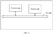
- the controller 103 is a computing device, for example, a server or a desktop computer. In terms of hardware, as shown in FIG. 2 , the controller 103 includes at least a processor 104, a memory 105, and a bus 106.
- the processor 104 is a central processing unit (English: central processing unit, CPU), and is configured to process an I/O request from the node 100 or a request generated in the controller 103.
- One controller 103 may include a plurality of processors 104, and each processor includes a plurality of processor cores (not shown in the figure).
- the memory 105 is configured to temporarily store data received from the host 11 or data read from the hard disk.
- the controller 103 may temporarily store data in the plurality of write requests in the memory 105.
- a capacity of the memory 105 reaches a specific threshold, the data stored in the memory 105 is sent to the hard disk for storage.
- the memory 105 includes a volatile memory, a non-volatile memory, or a combination thereof.
- the volatile memory is, for example, a random-access memory (English: random-access memory, RAM).
- the non-volatile memory is, for example, any machine readable medium that can store program code, such as a flash memory chip, a floppy disk, a hard disk, a solid state disk (solid state disk, SSD), or an optical disc.
- the memory 105 has a power-off protection function.
- the power-off protection function means that the data stored in the memory 105 is not lost when the system is powered off and then powered on again.
- the bus 106 is configured to implement communication between the components in the controller 103.
- Storage space provided by the controller 103 for the host 11 is from the plurality of hard disks 107, but an actual address of the storage space provided by the hard disks is not directly exposed to the controller 103 or the host 11.
- physical storage space is virtualized into several logical units (logical unit, LU), which are provided for the host 11, and each logical unit has a unique logical unit number (logical unit number, LUN). Because the host 11 can directly sense the logical unit number, a person skilled in the art usually directly refers to the LUN as the logical unit.
- Each LUN has a LUN ID, which is used to identify the LUN.
- a specific location of data in an LUN may be determined based on a start address and a length (length) of the data.
- a person skilled in the art usually refers to a start address as a logical block address (logical block address, LBA). It can be understood that three factors: an LUN ID, an LBA, and a length identify a specific address segment.
- the host 11 generates a data access request, and the data access request usually carries an LUN ID, an LBA, and a length.
- the LUN ID, the LBA, and the length are referred to as a virtual address.
- an LUN to be accessed by the request and a specific location of the LUN may be determined based on the virtual address.
- the controller 103 stores a correspondence between the virtual address and an address at which the data is stored in the hard disk. Therefore, after receiving the data access request, the controller 103 may determine a corresponding physical address based on the correspondence, and indicate the hard disk to read or write the data.
- a distributed hash table (Distributed Hash Table, DHT) manner is usually used for routing when a storage node is selected.
- DHT Distributed Hash Table
- a hash ring is evenly divided into several parts, each part is referred to as one partition, and one partition corresponds to one address segment described above. All data access requests sent by the host 11 to the storage system are located to one address segment. For example, data is read from the address segment, or data is written into the address segment.
- a CPU resource, a memory resource, and another resource in the storage system need to be used (the CPU resource and the memory resource are usually combined into a computing resource in the industry) to process these data access requests.
- the CPU resource and the memory resource are provided by the controller 103.
- the storage node usually has a plurality of controllers 103, and each controller 103 includes a plurality of processors.
- a plurality of processors When the storage node executes a service request, a plurality of processors usually need to process in parallel a plurality of sub-requests obtained by splitting the service request. Because these sub-requests are associated with each other, forwarding and data interaction of the sub-requests between the plurality of processors are involved, and bandwidth resources between the processors are occupied.
- one CPU or one or more CPU cores in one CPU are allocated to one address segment set.
- the address segment set includes one or more address segments, and the address segments may be consecutive or nonconsecutive. All data access requests for accessing these address segments are executed by the allocated CPU, or executed by the allocated one or more CPU cores. Different CPUs or different CPU cores in one CPU are allocated to different address segment sets.
- one memory is allocated to each address segment set, and data (including both service data and metadata) related to a data access request for accessing an address segment included in the address segment set is temporarily stored in the allocated memory.
- data including both service data and metadata
- one memory is allocated to one address segment set, and different memories are allocated to different address segment sets.
- the memory herein includes but is not limited to the memory 105 in FIG. 2 .
- a processor has a memory, which is also referred to as a local memory of the processor.
- the local memory is usually integrated into a component together with the processor, or is directly or indirectly coupled to the processor. In this case, during memory allocation, the local memory of the processor that is allocated to the address segment set may be preferentially allocated to the address segment set.
- no memory is pre-allocated to an address segment set, and a memory is selected from a plurality of memories included in the storage system when any data access request needs to use a memory.
- resources used to process a data access request may further include a network resource and a hard disk resource.
- both the network resource and the hard disk resource may be pre-allocated to different address segment sets.
- the new resource and an original resource may be integrated and then reallocated to the address segment sets.
- One implementation is to re-divide address segment sets, keep a quantity of address segments unchanged, increase a quantity of address segment sets, reduce a quantity of address segments included in each address segment set, and then reallocate resources of the storage system to the adjusted address segment sets.
- Another implementation is to maintain an allocation relationship between some address segments in each address segment set and original resources, and allocate newly added resources to the other address segments in the address segment set. This implementation can reduce a change of a mapping relationship between an address segment and an original resource.
- each virtual node is a minimum unit for resource allocation.
- Resources in the storage system may be classified into several equal parts, and each equal part corresponds to one virtual node.
- each virtual unit corresponds to some CPU resources, some memory resources, some network resources, and some hard disk resources. For example, if the storage system has four nodes 100, each node has four controllers 103, each controller has four CPUs, and each CPU has 48 CPU cores, one node 100 has 768 CPU cores in total. If the storage system includes four nodes, there are 3072 cores in total.
- each CPU corresponds to 256 GB memory
- one controller has 1 TB memory
- one node has 4 TB memory
- the storage system has 16 TB memory in total. If all hardware resources included in the storage system are classified into 256 equal parts, there are 256 virtual nodes, a CPU resource corresponding to each virtual node is 12 CPU cores, and a memory resource corresponding to each virtual node is 0.0625 TB.
- one partition corresponds to one address segment. After a virtual node is introduced, one partition set corresponds to one virtual node, and one partition set includes a plurality of partitions.
- one address segment set corresponds to one virtual node, and one address segment set includes a plurality of address segments.
- an address segment is used as an input, and after calculation is performed by using a preset algorithm, a partition can be uniquely determined, and a virtual node can be further uniquely determined.
- each virtual node corresponds to 32 partition sets, and each partition set includes 32 partitions.
- a quantity of partitions included in the storage system remains unchanged. Even if virtual nodes are added to or removed from the storage system, only the 1024 partitions are re-allocated in the virtual nodes that are added or removed.
- creating a virtual node is not the only manner for implementing resource isolation. If there is no virtual node, resources may be directly allocated to each address segment set according to the foregoing description.
- this embodiment For creation of a virtual node in the storage system, this embodiment provides at least two creation manners.
- the virtual node is automatically created during initialization of the storage system.
- a specific process is as follows:
- the virtual node may be created based on any one of (1) a quantity of storage nodes, (2) a quantity of controllers, and (3) a quantity of CPUs that are included in the system, and a combination thereof.
- a quantity of created virtual nodes is less than or equal to the quantity of CPUs included in the system.
- a resource is allocated to each virtual node, a mapping relationship between each virtual node and the allocated resource is created (for this part of content, refer to the following descriptions of FIG. 3 to FIG. 6 ), and the created mapping relationship is stored in the host 11 and the front-end interface card 101.
- management software of the storage system provides an interface for an administrator.
- the administrator selects a quantity of to-be-created virtual nodes in the interface.
- the storage system creates virtual nodes according to an instruction, allocates a resource to each virtual node, creates a mapping relationship between each virtual node and the allocated resource (for this part of content, refer to the following descriptions of FIG. 3 to FIG. 6 ), and stores the created mapping relationship in the host 11 and the front-end interface card 101.
- the administrator may select a quantity of virtual nodes based on any one of (1) a quantity of storage nodes, (2) a quantity of controllers, and (3) a quantity of CPUs, a combination thereof, or based on another factor.
- a quantity of virtual nodes may be adjusted during running of the storage system. For example, the quantity of virtual nodes may be increased when a controller is added to the storage system, or the quantity of virtual nodes may be reduced when a controller is removed from the storage system, or the quantity of virtual nodes may be increased when a disk enclosure is added to the storage system, or the quantity of virtual nodes may be reduced when a disk enclosure is removed from the storage system. Even if a quantity of resources does not change, the storage system can still adjust the quantity of virtual nodes as specified by the administrator.
- FIG. 3 is a schematic diagram of an allocation relationship between a virtual node, a CPU resource, and a memory resource according to an embodiment of this application.
- all CPUs and all memories in the storage system form a computing resource pool
- the CPU resources and the memory resources included in the computing resource pool are classified into several computing resource groups, and each computing resource group is allocated to one virtual node. Different virtual nodes occupy different computing resource groups.
- Each computing resource group may use one CPU, or a plurality of computing resource groups may share one CPU.
- a computing resource group 0 uses a CPU_0
- a computing resource group 1 uses a CPU_1
- a computing resource group m and a computing resource group m+1 share a CPU_m
- a computing resource group n uses a CPU_n, where both m and n are integers greater than 1, and n is greater than m. It may be understood that there is further one or more computing resource groups between the computing resource group n and the computing resource group m.
- each computing resource group When a plurality of computing resource groups share one CPU, because the CPU includes a plurality of CPU cores (for example, 48 CPU cores), the plurality of CPU cores included in the CPU may be classified into a plurality of core groups, and each core group (including one or more CPU cores) is allocated to one virtual node.
- each computing resource group further includes a memory resource, and the memory resource included in each computing resource group may be a local memory of a CPU included in the computing resource group.
- a data access request corresponding to a virtual node is run on an allocated CPU, and the virtual node may use a local memory resource of the nearby CPU.
- a local memory of a CPU is a memory that is located in the same node as the CPU.
- a memory resource used by the computing resource group 0 is a Mem_0, and the Mem_0 is a local memory of the CPU_0.
- a memory resource used by the computing resource group 1 is a Mem_1, and the Mem_1 is a local memory of the CPU_1.
- the computing resource group m and the computing resource group m+1 share a Mem m, and the Mem_m is a local memory of the CPU_m.
- a memory resource used by the computing resource group n is a Mem n, and the Mem_n is a local memory of the CPU_n.
- one computing resource group is allocated to each virtual node.
- each virtual node corresponds to one CPU, or a plurality of virtual nodes share one CPU. Therefore, a service request allocated to a virtual node is executed by a specified CPU, thereby reducing scheduling and forwarding between CPUs.
- computing resource pool is only an implementation provided in this embodiment, and this embodiment may further provide another implementation.
- some or all CPUs in the storage system form CPU resources, and some of the CPU resources are allocated to each virtual node.
- some or all memories in the storage system form memory resources, and some of the memory resources are allocated to each virtual node.
- the network resources in this embodiment of this application mainly include link resources between the controller 103 and the disk enclosure.
- a plurality of logical links may be created on each back-end interface card 102, a plurality of connections may be established on each logical link, and these connections form a network resource pool.
- FIG. 4 is a schematic diagram of an allocation relationship between a virtual node and a network resource according to this application. As shown in FIG. 4 , the connections included in the network resource pool are classified into several link groups, and each link group uses one or more connections. For example, a link group 0 uses a connection_0, and the connection_0 is established on a logical link 0. A connection group 1 uses a connection_1, and the connection 1 is established on a logical link_1.
- a connection group P uses all connections between a connection_m and a connection n, where both m and n are integers greater than 1, n is greater than m. There are one or more connections between the connection_m and the connection n, and these connections are established on a logical link n. Each link group is allocated to one virtual node. Because different virtual nodes use different connections, contention for network resources caused by exchange between the nodes in the system is avoided.
- network resource pool is only an implementation provided in this embodiment, and this embodiment may further provide another implementation.
- some or all of connections between the controller 103 and the disk enclosure form network resources, and some of the network resources are allocated to each virtual node.
- FIG. 5 is a schematic diagram of an allocation relationship between a virtual node and a hard disk resource according to an embodiment of this application.
- the disks are classified into several chunks (chunk) at a specified granularity. These chunks form a storage pool.
- a redundant array of independent disks Redundant Array of Independent Disks, RAID
- a specific quantity of chunks are selected from different disks to form a chunk group (chunk group, CKG).
- a chunk group 0 includes a chunk 0, a chunk m, and a chunk_n.
- the chunk_0 is from a hard disk_0
- the chunk_m is from a hard disk_1
- the chunk_n is from a hard disk n.
- Each virtual node corresponds to one or more chunk groups. Because different virtual nodes use different CKGs, back-end hard disk resources are isolated.
- the foregoing storage pool is only an implementation provided in this embodiment, and this embodiment may further provide another implementation.
- some or all hard disks included in the storage system form hard disk resources, and some of the hard disk resources are allocated to each virtual node.
- each virtual node includes a CPU resource, a memory resource, a network resource, and a hard disk resource that are needed for processing a service.
- computing resources allocated to a virtual node 0 are the computing resource group 0
- hard disk resources allocated to the virtual node 0 are a chunk group 1 and a chunk group 2
- network resources allocated to the virtual node 0 are a link group m and a link group n.
- Resources allocated to virtual nodes are independent of each other. As a quantity of CPUs and a quantity of CPU cores increase linearly, as long as performance of a single virtual node keeps consistent by correspondingly increasing a quantity of virtual nodes, performance can be linearly expanded as a quantity of physical resources increases. This technology described in this embodiment is referred to as a CoreFarm in the industry.
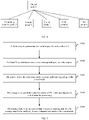
- FIG. 7 is a schematic flowchart of write request processing according to an embodiment. As shown in FIG. 7 , the following steps are included.
- a client triggers generation of a write request by using a host 11, where the write request carries to-be-written data and a virtual address of the data, and the virtual address is an LUN ID, an LBA, and a length.
- the host 11 determines a virtual node corresponding to the write request.
- the host 11 performs hash calculation on the virtual address, to obtain a hash value.
- the hash value corresponds to a specific partition, and then an identifier of the partition is mapped to a specific virtual node (referred to as a target virtual node) in a plurality of virtual nodes according to a specific rule.
- the rule includes but is not limited to a sequential algorithm, a random algorithm, and the like.
- the target virtual node is the virtual node 0 in FIG. 5 is used in this embodiment.
- hardware resources allocated to the virtual node 0 include the computing resource group 0, the chunk group 1, the chunk group 2, the link group m, and the link group n.
- the host 11 sends the write request to a storage node corresponding to the virtual node. Specifically, the host 11 stores a mapping table of a resource allocation status of each virtual node. The mapping table records a correspondence between each virtual node and each resource allocated to the virtual node (as shown in Table 1).
- Table 1 Virtual node Computing resource group Chunk group Link group Virtual node 0 Computing resource group 0 Chunk group 1 and chunk group 2 Link group m and link group n Virtual node 1 Computing resource group 1 Chunk group 0 Link group 1 ... ... ... ... Virtual node p Computing resource group p Chunk group p Link group p
- the host 11 determines, based on a computing resource that corresponds to the virtual node 0 and that is recorded in Table 1, a storage node in which the computing resource is located. It can be learned from the description in FIG. 5 that a CPU corresponding to the virtual node 0 is located in the computing resource group 0. Further, it can be learned from FIG. 2 that the computing resource group 0 includes the CPU_0 and the Mem_0. Therefore, the host 11 sends the write request to a storage node (for example, the storage node 0) in which the CPU_0 is located.
- a storage node for example, the storage node 0
- the write request may be sent to another storage node through a link between the host 11 and the another storage node, and then the another storage node forwards the write request to the storage node 0. If there is one link between the host 11 and the storage node 0, the write request is directly sent to the storage node 0 through the link. If there are a plurality of links between the host 11 and the storage node 0, one link may be selected from the plurality of links in a polling manner or another manner, and the write request is sent to the storage node 0 through the selected link.
- a front-end interface card 101 of the storage node stores a mapping table (as shown in Table 1) of a resource allocation status of each virtual node.
- the front-end interface card 101 may determine a corresponding target virtual node based on the virtual address carried in the write request, to further determine a CPU corresponding to the target virtual node.
- a CPU corresponding to the virtual node 0 is the CPU_0. Therefore, the front-end interface card 101 sends the write request to the CPU_0.
- the CPU may perform corresponding processing on the data in the write request. Data before processing and data after processing need to be temporarily stored in a memory. It can be learned from FIG. 2 that a memory resource included in the computing resource group 0 is the Mem_0. Therefore, the data may be stored in memory space indicated by the Mem_0.
- the storage node sends processed data to a corresponding hard disk for storage through a back-end physical channel that matches the virtual node. Specifically, when data stored in the memory Mem 0 reaches a specific watermark, the data stored in the memory Mem_0 needs to be written into the hard disk for persistent storage.
- the storage node may search the mapping table for a chunk group corresponding to the target virtual node, and write the to-be-written data into the chunk group corresponding to the target virtual node. For example, it can be learned from FIG. 5 and Table 1 that chunk groups corresponding to the virtual node 0 are the chunk group 1 and the chunk group 2. It indicates that the virtual node 0 may use a hard disk resource of the chunk group 1 or a hard disk resource of the chunk group 2.
- the chunk group 0 includes the chunk 0, the chunk m, and the chunk_n.
- the chunk_0 is located in the hard disk_0
- the chunk_m is located in the hard disk_1
- the chunk_n is located in the hard disk_n.
- the storage node 0 may divide the to-be-written data into two data slices, obtain a check slice of the two data slices through calculation, and then send the two data slices and the check slice to the hard disk_0, the hard disk_1, and the hard disk n respectively through the back-end interface card 102.
- the storage node 0 needs to use network resources in a network resource pool to send the data slices and the check slice.
- network resources corresponding to the virtual node 0 include the link group m and the link group n. Therefore, the back-end interface card 102 may send the data slices and the check slice in parallel to a corresponding hard disk by using a plurality of connections included in the link group m and/or the link group n.
- the host 11 first determines the virtual node corresponding to the write request, and then processes the request by using the hardware resources pre-allocated to the virtual node. Because resources allocated to virtual nodes are independent of each other, when the host 11 processes a plurality of data processing requests in parallel, the plurality of data processing requests do not interfere with each other.
- FIG. 7 Processing the write request is used as an example for description in FIG. 7 .
- a storage system further processes another service request such as data exchange, protocol parsing, and data flushing.
- these service requests are usually executed by a plurality of CPUs or a plurality of CPU cores in one CPU in series.
- a key to affecting linearity is overheads caused by cross-CPU and cross-CPU-core processing and serial execution in the storage system.
- a CPU packet scheduling method is provided to resolve the problem.
- FIG. 8 is a schematic diagram of packet scheduling of a CPU core in a virtual node.
- a virtual node corresponds to one CPU, and correspondingly, it means that one virtual node uses one CPU, or a plurality of virtual nodes share one CPU. In this way, it is ensured that service requests for a same virtual node are processed by a same CPU. Therefore, service scheduling remains independent between virtual nodes.
- a plurality of CPU cores included in the CPU corresponding to the virtual node are classified into several service processing groups based on service logic, and each service processing group includes one or more CPU cores.
- a first service processing group is specially used for I/O read and write
- a second service processing group is specially used for data exchange
- a third service processing group is used for protocol parsing
- a fourth service processing group is used for data flushing.
- CPU cores included in the third service processing group and the fourth service processing group may be shared. Specifically, for example, one CPU includes 48 CPU cores. It is assumed that 12 CPU cores are allocated to the first service processing group, 12 CPU cores are allocated to the second service processing group, and 24 CPU cores are allocated to both the third service processing group and the fourth service processing group.
- Different service requests are isolated in such a manner.
- service requests are executed in series on a CPU core allocated to the service processing group, so as to prevent the service request from contending for resources with other service requests to some extent, thereby reducing mutually exclusive operations and implementing a lock-free design.
- a processing capability of the CPU can also be linearly expanded.
- the service requests are grouped, there is less service code than that before the grouping, and the service code occupies less memory space accordingly. When a total amount of memory space remains unchanged, more space can be spared in the memory to store service data, so as to increase a memory hit rate of the data.
- the host 11 may determine, based on a virtual address of to-be-read data carried in the read request, a virtual node corresponding to the request, and further determine a storage node corresponding to the virtual node (similar to S103). The host 11 sends the read request to the storage node corresponding to the virtual node. After receiving the read request, the storage node sends the read request to a CPU corresponding to the virtual node for processing (similar to S104).
- the CPU corresponding to the virtual node may further determine a network resource and a hard disk resource that correspond to the virtual node, and then send the request to a corresponding hard disk by using the corresponding network resource, to read the to-be-read data.
- the cost of improving a capability of the storage system by improving a single-core capability is increasing.
- a plurality of nodes are used in the industry, and each node has a plurality of CPU cores.
- a processing capability of the storage system is improved.
- a quantity of cores in the storage system increases from 48 to 768
- a hardware capability of the storage system improves.
- how to enable a service processing capability of the storage system to be linearly expanded as a quantity of CPU cores and a quantity of resources such as memory resources increase is a problem that all storage device vendors need to resolve.
- the service processing capability of the storage system can be linearly expanded as a quantity of hardware resources increases. The following describes a node capacity expansion process. The process is described with reference to FIG. 3 to FIG. 6 .
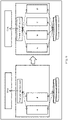
- FIG. 9 is a schematic diagram of a type of capacity expansion of a storage system according to an embodiment of this application
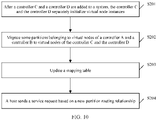
- FIG. 10 is a schematic flowchart of a capacity expansion method according to an embodiment of this application.
- This embodiment is described by using an example in which a quantity of controllers is expanded in a node. It is assumed that the node includes two controllers before expansion: a controller A and a controller B. After two controllers (a controller C and a controller D) are added, the node includes four controllers. A front-end interface card 101 and a back-end interface card 102 are shared by the controllers before and after the expansion.
- the expansion method includes the following steps.
- the controller C and the controller D separately initialize virtual node instances. It may be understood that, when a quantity of controllers increases, CPU resources and memory resources that can be provided by the entire node increase accordingly. Therefore, as long as a quantity of virtual nodes increases, a processing capability of the entire node can be improved by allocating a newly added CPU resource and a newly added memory resource to a newly added virtual node.
- the controller C is used as an example.
- the controller C creates a plurality of virtual nodes based on a quantity of CPUs included in the controller C. Because one CPU is allocated to one virtual node in this embodiment, a quantity of virtual nodes may be less than or equal to the quantity of CPUs included in the controller C. For example, if the controller C includes eight CPUs, the controller C may create a maximum of eight virtual nodes. After the quantity of virtual nodes is determined, a mapping relationship between a newly added virtual node and a CPU and a mapping relationship between a newly added virtual node and a memory are further determined.
- a virtual node x corresponds to a CPU_x (x represents a positive integer), and a memory resource needed by the virtual node x may be a local memory (for example, a Mem_x) of the CPU_x. Therefore, the CPU x and the Mem_x form a computing resource group, which is allocated to the virtual node x.
- a virtual node x+1 corresponds to a CPU_x+1, and a memory resource needed by the virtual node x+1 may be a local memory (for example, a Mem_x+1) of the CPU_x+1. Therefore, the CPU_x+1 and the Mem_x+1 form another computing resource group, which is allocated to the virtual node x+1.
- a manner of creating a virtual node by the controller D is similar to that of creating the virtual node by the controller C.
- the controller C and the controller D establish physical links with the back-end interface card 102.
- a plurality of logical links are created on these physical links, and a plurality of connections may be established on each logical link.
- These connections are added to the network resource pool shown in FIG. 4 , to expand network resources in the network resource pool.
- These newly added network resources may be classified into several link groups, and each link group includes one or more connections. Then, each link group is allocated to one newly added virtual node.
- the virtual node x corresponds to a link group x (x represents a positive integer)
- the virtual node x+1 corresponds to a link group x+1.
- S202 Migrate some partitions belonging to virtual nodes of the controller A and the controller B to virtual nodes of the controller C and the controller D. It can be learned from the foregoing description that a service request from a host 11 is routed to a virtual node based on a partition corresponding to a virtual address. When a total quantity of partitions included in the storage system remains unchanged, to enable newly created virtual nodes to bear the service request, some partitions belonging to original virtual nodes need to be migrated to the newly created virtual nodes. For example, before capacity expansion, one virtual node corresponds to one partition set, and one partition set includes 32 partitions. After capacity expansion, one virtual node corresponds to 24 partitions.
- One implementation is to re-establish a mapping relationship between all partitions in the storage system and all virtual nodes (including both the original virtual nodes and the newly added virtual nodes), and the other implementation is to migrate some partitions in an original partition set to the newly added virtual nodes, and retain a correspondence between the remaining partitions and the original virtual nodes.
- eight partitions in the original partition set need to be migrated to the newly added virtual nodes.
- a quantity of to-be-migrated partitions depends on a proportion of a quantity of newly added virtual nodes in a quantity of virtual nodes included in the entire node.
- a migration algorithm is not limited in this embodiment, provided that partitions are evenly distributed in all virtual nodes.
- mapping table includes both a mapping table stored in the host 11 and a mapping table in the front-end interface card 101.
- CPU resources, memory resources, and network resources are allocated to the newly added virtual nodes. These newly added allocation relationships need to be recorded in the mapping table for processing service requests. Because there is no hard disk in the controller C and the controller D, hard disk resources needed by the newly added virtual nodes are still from the storage pool shown in FIG. 5 . Specifically, chunk groups belonging to the original virtual nodes may be migrated to the newly added virtual nodes.
- a migration algorithm is not limited in this embodiment, provided that chunk groups allocated to all virtual nodes are approximately equal.
- Table 2 Virtual node Computing resource group Chunk group Link group Virtual node 0 Computing resource group 0 Chunk group 1 and chunk group 2 Link group m and link group n Virtual node 1 Computing resource group 1 Chunk group 0 Link group 1 ... ... ... ... Virtual node p Computing resource group p Chunk group p Link group p ... ... ... ... Virtual node x Computing resource group x Chunk group p+1 Link group x Virtual node x+1 Computing resource group x+1 Chunk group p+2 Link group x+1 ... ... ... ... ...
- the host 11 sends the service request based on a new partition routing relationship.
- For a manner of processing the service request refer to the schematic flowchart of processing a write request shown in FIG. 6 . Details are not described herein again.
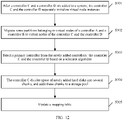
- FIG. 11 is a schematic diagram of another type of capacity expansion of a storage system according to an embodiment of this application
- FIG. 12 is a schematic flowchart of another expansion method according to an embodiment of this application.
- the node includes two controllers: a controller A and a controller B before capacity expansion. After two controllers (a controller C and a controller D) are added, the node includes four controllers.
- a front-end interface card 101 and a back-end interface card 102 are shared by the controllers before and after the expansion.
- the method includes the following steps.
- the controller C divides space of newly added hard disks into several chunks, and adds these chunks to a storage pool.
- the controller C or the controller D receives a write request, the write request corresponds to newly added virtual nodes, and chunks from different hard disks form a chunk group to accommodate data carried in the write request. It can be learned that a plurality of newly added chunk groups in the storage pool may be allocated to the newly added virtual nods. Each virtual node uses one or more chunk groups.
- S305 Update a mapping table, where the mapping table includes both a mapping table stored in a host and a mapping table in the front-end interface card 101.
- S203 shown in FIG. 9 .
- a quantity of hard disk resources does not increase, and therefore chunk groups corresponding to the newly added virtual nodes are obtained by migrating chunk groups of original virtual nodes in the system.
- the chunk groups corresponding to the newly added virtual nodes are from the newly added hard disk resources.
- newly added hard disk resources are allocated to newly added virtual nodes, and data carried in the write request corresponding to the newly added virtual nodes may be written into the newly added hard disks.
- a large amount of old data is still stored in original hard disks.
- one manner is to migrate some old data to the new hard disks for storage, and another manner is not to actively migrate the old data, but migrate valid data (data that is not modified) in the old data to the newly added hard disks when garbage collection is performed on the old data.
- an increasing amount of junk data is generated. After several garbage collection operations, the data can be evenly distributed.
- An advantage of this manner is that because the data is not actively migrated, bandwidth overheads between nodes or between controllers can be reduced.
- All or some of the foregoing embodiments may be implemented by using software, hardware, firmware, or any combination thereof.
- the embodiments may be implemented completely or partially in a form of a computer program product.
- the computer program product includes one or more computer instructions.
- the computer program instructions When the computer program instructions are loaded or executed on a computer, the procedure or functions according to the embodiments of the present invention are all or partially generated.
- the computer may be a general-purpose computer, a dedicated computer, a computer network, or another programmable apparatus.
- the computer instructions may be stored in a computer-readable storage medium or may be transmitted from a computer-readable storage medium to another computer-readable storage medium.
- the computer instructions may be transmitted from a website, computer, server, or data center to another website, computer, server, or data center in a wired (for example, a coaxial cable, an optical fiber, or a digital subscriber line (DSL)) or wireless (for example, infrared, radio, or microwave) manner.
- the computer-readable storage medium may be any usable medium accessible by the computer, or a data storage device, such as a server or a data center, integrating one or more usable media.
- the usable medium may be a magnetic medium (for example, a floppy disk, a hard disk, or a magnetic tape), an optical medium (for example, a DVD), a semiconductor medium (for example, a solid state disk (Solid State Disk (SSD)), or the like.
- a magnetic medium for example, a floppy disk, a hard disk, or a magnetic tape
- an optical medium for example, a DVD
- a semiconductor medium for example, a solid state disk (Solid State Disk (SSD)
- the disclosed system, apparatus, and method may be implemented in other manners.
- the described apparatus embodiment is merely an example.
- the unit division is merely logical function division and may be other division in actual implementation.
- a plurality of units or components may be combined or integrated into another system, or some features may be ignored or not performed.
- the displayed or discussed mutual couplings or direct couplings or communication connections may be implemented by using some interfaces.
- the indirect couplings or communication connections between the apparatuses or units may be implemented in electronic, mechanical, or other forms.
- the units described as separate parts may or may not be physically separate, and parts displayed as units may or may not be physical units, may be located in one position, or may be distributed on a plurality of network units. Some or all of the units may be selected based on actual requirements to achieve the objectives of the solutions of the embodiments.
- the functions When the functions are implemented in the form of a software functional unit and sold or used as an independent product, the functions may be stored in a computer-readable storage medium. Based on such an understanding, the technical solutions of this application essentially, or the part contributing to the prior art, or some of the technical solutions may be implemented in a form of a software product.
- the software product is stored in a storage medium, and includes several instructions for instructing a computer device (which may be a personal computer, a storage node, or a network device) to perform all or some of the steps of the methods described in the embodiments of this application.
- the foregoing storage medium includes: any medium that can store program code, such as a USB flash drive, a removable hard disk, a read-only memory (Read-Only Memory, ROM), a random access memory (Random Access Memory, RAM), a magnetic disk, or an optical disc.
- program code such as a USB flash drive, a removable hard disk, a read-only memory (Read-Only Memory, ROM), a random access memory (Random Access Memory, RAM), a magnetic disk, or an optical disc.
Landscapes
- Engineering & Computer Science (AREA)
- Theoretical Computer Science (AREA)
- Physics & Mathematics (AREA)
- General Engineering & Computer Science (AREA)
- General Physics & Mathematics (AREA)
- Human Computer Interaction (AREA)
- Software Systems (AREA)
- Information Retrieval, Db Structures And Fs Structures Therefor (AREA)
Applications Claiming Priority (3)
| Application Number | Priority Date | Filing Date | Title |
|---|---|---|---|
| CN201910646566 | 2019-07-17 | ||
| CN201910955603.XA CN112241320B (zh) | 2019-07-17 | 2019-10-09 | 资源分配方法、存储设备和存储系统 |
| PCT/CN2020/088784 WO2021008197A1 (fr) | 2019-07-17 | 2020-05-06 | Procédé d'attribution de ressources, dispositif de stockage et système de stockage |
Publications (2)
| Publication Number | Publication Date |
|---|---|
| EP3992792A1 true EP3992792A1 (fr) | 2022-05-04 |
| EP3992792A4 EP3992792A4 (fr) | 2022-08-17 |
Family
ID=74168311
Family Applications (1)
| Application Number | Title | Priority Date | Filing Date |
|---|---|---|---|
| EP20840105.9A Pending EP3992792A4 (fr) | 2019-07-17 | 2020-05-06 | Procédé d'attribution de ressources, dispositif de stockage et système de stockage |
Country Status (5)
| Country | Link |
|---|---|
| US (2) | US11861196B2 (fr) |
| EP (1) | EP3992792A4 (fr) |
| JP (1) | JP7467593B2 (fr) |
| CN (1) | CN112241320B (fr) |
| WO (1) | WO2021008197A1 (fr) |
Families Citing this family (5)
| Publication number | Priority date | Publication date | Assignee | Title |
|---|---|---|---|---|
| US11451456B2 (en) * | 2019-04-19 | 2022-09-20 | Cisco Technology, Inc. | Learning stable representations of devices for clustering-based device classification systems |
| JP2024509954A (ja) * | 2021-03-12 | 2024-03-05 | 華為技術有限公司 | メモリ共有制御方法及びデバイス、コンピュータデバイス、並びにシステム |
| CN113485789B (zh) * | 2021-06-30 | 2023-03-21 | 海光信息技术股份有限公司 | 资源配置方法、装置及计算机架构 |
| CN113849317B (zh) * | 2021-11-29 | 2022-03-22 | 苏州浪潮智能科技有限公司 | 一种内存池资源使用方法及相关装置 |
| CN115865803B (zh) * | 2023-03-03 | 2023-08-22 | 浪潮电子信息产业股份有限公司 | 一种io请求处理方法、装置、设备及可读存储介质 |
Family Cites Families (19)
| Publication number | Priority date | Publication date | Assignee | Title |
|---|---|---|---|---|
| US6578128B1 (en) * | 2001-03-29 | 2003-06-10 | Emc Corporation | Address management for a shared memory region on a multi-processor controller board |
| US6643722B1 (en) * | 2001-03-29 | 2003-11-04 | Emc Corporation | Data storage system having director boards with plural processors |
| US7277897B2 (en) * | 2003-08-01 | 2007-10-02 | Oracle International Corporation | Dynamic reassignment of data ownership |
| JP4859471B2 (ja) * | 2006-02-02 | 2012-01-25 | 株式会社日立製作所 | ストレージシステム及びストレージコントローラ |
| JP4680851B2 (ja) * | 2006-08-18 | 2011-05-11 | 富士通株式会社 | システムコントローラ,同一アドレスリクエストキューイング防止方法および情報処理装置 |
| JP4932390B2 (ja) * | 2006-08-31 | 2012-05-16 | 株式会社日立製作所 | 仮想化システム及び領域割当て制御方法 |
| JP2008134775A (ja) * | 2006-11-28 | 2008-06-12 | Hitachi Ltd | 記憶サブシステム及びこれを利用したリモートコピーシステム |
| US7987352B2 (en) * | 2007-11-30 | 2011-07-26 | Intel Corporation | Booting with sub socket partitioning |
| CN102446159B (zh) * | 2010-10-12 | 2013-09-18 | 无锡江南计算技术研究所 | 多核处理器的数据管理方法及装置 |
| CN102033768B (zh) * | 2010-12-10 | 2013-10-30 | 杭州海康威视数字技术股份有限公司 | 多cpu系统的启动方法及多cpu系统 |
| US20140101394A1 (en) | 2012-10-04 | 2014-04-10 | Hitachi, Ltd. | Computer system and volume management method for the computer system |
| US9740404B2 (en) | 2013-05-31 | 2017-08-22 | Hitachi, Ltd. | Control apparatus and control method |
| CN104995603A (zh) * | 2013-11-14 | 2015-10-21 | 联发科技股份有限公司 | 至少部分基于共享相同数据及/或存取相同存储地址的任务分布的任务调度方法以及多核处理器系统中用于分配任务的相关非暂时性计算机可读介质 |
| CN109101286A (zh) * | 2014-07-08 | 2018-12-28 | 北京航空航天大学 | 一种基于多核处理器架构的机器人混合系统应用框架 |
| WO2016121066A1 (fr) * | 2015-01-29 | 2016-08-04 | 株式会社日立製作所 | Système de stockage |
| CN105677580B (zh) * | 2015-12-30 | 2019-04-12 | 杭州华为数字技术有限公司 | 访问缓存的方法和装置 |
| WO2019071595A1 (fr) * | 2017-10-13 | 2019-04-18 | 华为技术有限公司 | Procédé et dispositif de stockage de données dans un système de stockage de blocs distribué et support de stockage lisible par ordinateur |
| CN109407975B (zh) * | 2018-09-19 | 2020-08-25 | 华为技术有限公司 | 写数据方法与计算节点以及分布式存储系统 |
| US11520674B2 (en) * | 2019-09-13 | 2022-12-06 | EMC IP Holding Company LLC | Managing containers on a data storage system |
-
2019
- 2019-10-09 CN CN201910955603.XA patent/CN112241320B/zh active Active
-
2020
- 2020-05-06 WO PCT/CN2020/088784 patent/WO2021008197A1/fr unknown
- 2020-05-06 JP JP2022502969A patent/JP7467593B2/ja active Active
- 2020-05-06 EP EP20840105.9A patent/EP3992792A4/fr active Pending
-
2022
- 2022-01-14 US US17/575,795 patent/US11861196B2/en active Active
-
2023
- 2023-11-29 US US18/523,798 patent/US20240094933A1/en active Pending
Also Published As
| Publication number | Publication date |
|---|---|
| US20240094933A1 (en) | 2024-03-21 |
| JP2022541261A (ja) | 2022-09-22 |
| WO2021008197A1 (fr) | 2021-01-21 |
| JP7467593B2 (ja) | 2024-04-15 |
| US20220137819A1 (en) | 2022-05-05 |
| EP3992792A4 (fr) | 2022-08-17 |
| US11861196B2 (en) | 2024-01-02 |
| CN112241320A (zh) | 2021-01-19 |
| CN112241320B (zh) | 2023-11-10 |
Similar Documents
| Publication | Publication Date | Title |
|---|---|---|
| EP3992792A1 (fr) | Procédé d'attribution de ressources, dispositif de stockage et système de stockage | |
| US11082206B2 (en) | Layout-independent cryptographic stamp of a distributed dataset | |
| US11237746B2 (en) | Storage system and node management method | |
| JP5510556B2 (ja) | 仮想マシンのストレージスペースおよび物理ホストを管理するための方法およびシステム | |
| US8447943B2 (en) | Reduction of I/O latency for writable copy-on-write snapshot function | |
| US11693789B2 (en) | System and method for mapping objects to regions | |
| US20190163395A1 (en) | Storage system and control method thereof | |
| EP2254036A2 (fr) | Appareil de stockage et procédé de copie de données | |
| US11262916B2 (en) | Distributed storage system, data processing method, and storage node | |
| US11899533B2 (en) | Stripe reassembling method in storage system and stripe server | |
| US20210278983A1 (en) | Node Capacity Expansion Method in Storage System and Storage System | |
| US7669031B2 (en) | Computer system, storage area allocation method, and management computer | |
| US11675545B2 (en) | Distributed storage system and storage control method | |
| JP2022034455A (ja) | 計算機システムおよび管理方法 | |
| CN113805789A (zh) | 存储设备中的元数据处理方法及相关设备 | |
| US11593182B2 (en) | Storage system | |
| CN117389485B (zh) | 存储性能优化方法、装置、存储系统、电子设备和介质 | |
| EP4152163A1 (fr) | Procédé de traitement de métadonnées dans un dispositif de stockage et dispositif associé | |
| US20230021806A1 (en) | Distributed storage system and volume management method | |
| JP6657990B2 (ja) | ストレージ装置、仮想ボリューム制御システム、仮想ボリューム制御方法および仮想ボリューム制御プログラム |
Legal Events
| Date | Code | Title | Description |
|---|---|---|---|
| STAA | Information on the status of an ep patent application or granted ep patent |
Free format text: STATUS: THE INTERNATIONAL PUBLICATION HAS BEEN MADE |
|
| PUAI | Public reference made under article 153(3) epc to a published international application that has entered the european phase |
Free format text: ORIGINAL CODE: 0009012 |
|
| STAA | Information on the status of an ep patent application or granted ep patent |
Free format text: STATUS: REQUEST FOR EXAMINATION WAS MADE |
|
| 17P | Request for examination filed |
Effective date: 20220128 |
|
| AK | Designated contracting states |
Kind code of ref document: A1 Designated state(s): AL AT BE BG CH CY CZ DE DK EE ES FI FR GB GR HR HU IE IS IT LI LT LU LV MC MK MT NL NO PL PT RO RS SE SI SK SM TR |
|
| A4 | Supplementary search report drawn up and despatched |
Effective date: 20220718 |
|
| RIC1 | Information provided on ipc code assigned before grant |
Ipc: G06F 9/50 20060101AFI20220712BHEP |
|
| DAV | Request for validation of the european patent (deleted) | ||
| DAX | Request for extension of the european patent (deleted) |