EP3992522A1 - Elektrisches modul zum anschluss an eine tragschiene - Google Patents
Elektrisches modul zum anschluss an eine tragschiene Download PDFInfo
- Publication number
- EP3992522A1 EP3992522A1 EP21204894.6A EP21204894A EP3992522A1 EP 3992522 A1 EP3992522 A1 EP 3992522A1 EP 21204894 A EP21204894 A EP 21204894A EP 3992522 A1 EP3992522 A1 EP 3992522A1
- Authority
- EP
- European Patent Office
- Prior art keywords
- electrical module
- contacting
- actuating arm
- mounting rail
- seal
- Prior art date
- Legal status (The legal status is an assumption and is not a legal conclusion. Google has not performed a legal analysis and makes no representation as to the accuracy of the status listed.)
- Granted
Links
Images


Classifications
-
- F—MECHANICAL ENGINEERING; LIGHTING; HEATING; WEAPONS; BLASTING
- F21—LIGHTING
- F21V—FUNCTIONAL FEATURES OR DETAILS OF LIGHTING DEVICES OR SYSTEMS THEREOF; STRUCTURAL COMBINATIONS OF LIGHTING DEVICES WITH OTHER ARTICLES, NOT OTHERWISE PROVIDED FOR
- F21V21/00—Supporting, suspending, or attaching arrangements for lighting devices; Hand grips
- F21V21/34—Supporting elements displaceable along a guiding element
- F21V21/35—Supporting elements displaceable along a guiding element with direct electrical contact between the supporting element and electric conductors running along the guiding element
-
- F—MECHANICAL ENGINEERING; LIGHTING; HEATING; WEAPONS; BLASTING
- F21—LIGHTING
- F21V—FUNCTIONAL FEATURES OR DETAILS OF LIGHTING DEVICES OR SYSTEMS THEREOF; STRUCTURAL COMBINATIONS OF LIGHTING DEVICES WITH OTHER ARTICLES, NOT OTHERWISE PROVIDED FOR
- F21V31/00—Gas-tight or water-tight arrangements
- F21V31/005—Sealing arrangements therefor
-
- F—MECHANICAL ENGINEERING; LIGHTING; HEATING; WEAPONS; BLASTING
- F21—LIGHTING
- F21Y—INDEXING SCHEME ASSOCIATED WITH SUBCLASSES F21K, F21L, F21S and F21V, RELATING TO THE FORM OR THE KIND OF THE LIGHT SOURCES OR OF THE COLOUR OF THE LIGHT EMITTED
- F21Y2115/00—Light-generating elements of semiconductor light sources
- F21Y2115/10—Light-emitting diodes [LED]
-
- H—ELECTRICITY
- H01—ELECTRIC ELEMENTS
- H01R—ELECTRICALLY-CONDUCTIVE CONNECTIONS; STRUCTURAL ASSOCIATIONS OF A PLURALITY OF MUTUALLY-INSULATED ELECTRICAL CONNECTING ELEMENTS; COUPLING DEVICES; CURRENT COLLECTORS
- H01R13/00—Details of coupling devices of the kinds covered by groups H01R12/70 or H01R24/00 - H01R33/00
- H01R13/46—Bases; Cases
- H01R13/52—Dustproof, splashproof, drip-proof, waterproof, or flameproof cases
-
- H—ELECTRICITY
- H01—ELECTRIC ELEMENTS
- H01R—ELECTRICALLY-CONDUCTIVE CONNECTIONS; STRUCTURAL ASSOCIATIONS OF A PLURALITY OF MUTUALLY-INSULATED ELECTRICAL CONNECTING ELEMENTS; COUPLING DEVICES; CURRENT COLLECTORS
- H01R25/00—Coupling parts adapted for simultaneous co-operation with two or more identical counterparts, e.g. for distributing energy to two or more circuits
- H01R25/14—Rails or bus-bars constructed so that the counterparts can be connected thereto at any point along their length
- H01R25/142—Their counterparts
-
- H—ELECTRICITY
- H01—ELECTRIC ELEMENTS
- H01R—ELECTRICALLY-CONDUCTIVE CONNECTIONS; STRUCTURAL ASSOCIATIONS OF A PLURALITY OF MUTUALLY-INSULATED ELECTRICAL CONNECTING ELEMENTS; COUPLING DEVICES; CURRENT COLLECTORS
- H01R25/00—Coupling parts adapted for simultaneous co-operation with two or more identical counterparts, e.g. for distributing energy to two or more circuits
- H01R25/16—Rails or bus-bars provided with a plurality of discrete connecting locations for counterparts
- H01R25/161—Details
-
- H—ELECTRICITY
- H01—ELECTRIC ELEMENTS
- H01R—ELECTRICALLY-CONDUCTIVE CONNECTIONS; STRUCTURAL ASSOCIATIONS OF A PLURALITY OF MUTUALLY-INSULATED ELECTRICAL CONNECTING ELEMENTS; COUPLING DEVICES; CURRENT COLLECTORS
- H01R31/00—Coupling parts supported only by co-operation with counterpart
- H01R31/06—Intermediate parts for linking two coupling parts, e.g. adapter
-
- H—ELECTRICITY
- H02—GENERATION; CONVERSION OR DISTRIBUTION OF ELECTRIC POWER
- H02G—INSTALLATION OF ELECTRIC CABLES OR LINES, OR OF COMBINED OPTICAL AND ELECTRIC CABLES OR LINES
- H02G3/00—Installations of electric cables or lines or protective tubing therefor in or on buildings, equivalent structures or vehicles
- H02G3/02—Details
- H02G3/08—Distribution boxes; Connection or junction boxes
- H02G3/088—Dustproof, splashproof, drip-proof, waterproof, or flameproof casings or inlets
Definitions
- the present invention relates to an electrical module which is designed in particular as a light and/or as a camera and/or as a sensor unit and can be coupled to a mounting rail, the mounting rail having a mounting rail profile with two side walls and at least one conductor rail arranged in the mounting rail profile has contactable lines.
- Support rails with a support rail profile and a busbar held in the support rail profile are known from the prior art and are used, for example, to implement elongated so-called continuous lighting systems.
- a well-known light line system is sold by the applicant under the name "TECTON" and is characterized in that lights or other electrical loads can be flexibly positioned on the mounting rail over the entire length of the system. This is made possible by the fact that due to a special mounting of the lines of the busbar, these are accessible to consumers over essentially the entire length of the continuous lighting system, so that the lines can be contacted not only at fixed positions, but at any point.
- the WO 2001/091250 A1 such a lighting system.
- two conductor rails are arranged opposite one another on the two side walls of a U-shaped carrier rail profile that is open at the bottom.
- the lines of the busbars are then contacted by the lamp or consumer having a rotatable contacting element, which is inserted into the mounting rail from the underside and then rotated by approximately 45°.
- Contacts arranged on the contacting element are designed in such a way that they are pivoted out to the side as a result of the twisting and ultimately contact the lines of the busbars in the twisted state.
- a carrier element is coupled to the contacting element, on which in turn the lighting means are attached.
- the present invention is therefore based on the task of specifying an improved adjustment system for the contacting element of the electrical module.
- an electrical module for connection to a mounting rail, which has a mounting rail profile with two side walls and at least one busbar, which is arranged on one of the two inner sides of the side walls of the mounting rail profile and has lines that can be electrically contacted.
- the electrical module has a contacting element which can be inserted into the mounting rail profile and has connection contacts which are intended to come into contact with lines of the busbar when the contacting element is inserted into the mounting rail profile.
- the contacting element is rotatably mounted about an axis of rotation relative to a carrier element of the electrical module between an open position, in which the contacting element can be inserted and removed from the mounting rail profile, and a contacting position, in which the connection contacts contact lines of the busbar.
- the carrier element has two side walls running parallel to one another, the contacting element being arranged between the two side walls running parallel to one another, and the contacting element being coupled to an actuating arm which is designed to move the contacting element from the open position to when actuated to move the contacting position and vice versa.
- the actuating arm is guided through a recess in one of the two side walls running parallel to one another, such that the actuating arm can be actuated from an outside of the electrical module.
- the actuating arm has a seal which is designed to seal off the recess in the contacting position of the contacting element.
- An electrical module for connection to a mounting rail is thus described, which can be coupled to the mounting rail by rotating the contacting element of the electrical module.
- the adjustment process can be operated conveniently and easily from the outside for a user by means of an outwardly guided actuating arm, the recess in a side wall of the electrical module also being sealed in the installed state, ie in the contacting position.
- the electrical module of this type can thus be installed simply by operating the actuating arm, as was previously the case, although not only is electrical and mechanical coupling to the mounting rail achieved by actuating the actuating arm, but the carrier element of the electrical module is also sealed at the recess.
- An adjustment system or an adjustment mechanism is thus specified which combines several application steps into a simple operation of the actuating arm.
- the seal does not seal the recess in the open position.
- the installation process ie the transition of the contacting element from the open position to the contacting position, can be carried out easily, with as little frictional resistance as possible arising from the seal.
- An embodiment is thus created in which the seal is preferably firmly connected to the actuating arm, so that the recess is only completely sealed in the contacting position. A particularly high degree of tightness can be achieved here.
- the seal itself thus counteracts inadvertent adjustment of the actuating arm in the contacting position.
- the seal at least partially encloses the recess.
- the seal has at least one sealing element, the sealing element preferably being a sealing lamella.
- the seal allows it to protect the recess more effectively against external influences such as dust, moisture and liquids, with the at least one sealing element, in particular the at least one sealing lamella, shielding the external influences.
- the seal particularly preferably has a plurality of sealing lamellae, with each individual sealing lamella being connected to the side wall, respectively cooperates with the walls of the recess, so as to seal the carrier element from the outside. With an increasing number of lamellae, a kind of labyrinth is created, which weakens the external influencing factors, so that the recess of the carrier element is sealed more tightly.
- the contacting element is coupled to a rotary element, with the rotary element preferably being connected to the actuating arm via a joint in such a way that the actuating arm can be moved in a straight line.
- the actuating arm can thus be operated particularly intuitively by a user. Furthermore, such an embodiment has a particularly advantageous effect on the adjustment process, with the seal being inserted in a straight line into the recess, so that the seal rests against the recess in a sealing manner as possible. As a result, the actuating arm can also be manufactured in a particularly space-saving and stable manner, since a force always acts from the same direction when the actuating arm is actuated.
- the movement of the actuating arm is preferably such that the actuating arm is moved perpendicularly to a longitudinal direction of the carrier element, so that the adjustment process of the contacting element takes place by pressing in or by pulling out the actuating arm.
- the joint is preferably designed in such a way that a linear movement of the actuating arm results in a rotary movement of the rotary element and of the contacting element coupled thereto.
- This configuration ensures that the rotational movement generated is only indirectly influenced by the user, which is particularly advantageous for the reliability of the adjustment mechanism.
- the operation by the user is also simplified.
- the rotating element has a latching element, with the latching element particularly preferably being arranged on a projection region of the rotating element.
- Such a configuration is particularly advantageous with regard to the functional reliability of the electrical module, since a specific position of the rotary element, and thus also of the contacting element, can be set by means of the latching element. can be locked.
- the open position and/or the contacting position can particularly preferably be fixed with such a latching element, so that the coupling of the electrical module to the mounting rail is particularly secure and simple.
- a linear movement of the actuating arm particularly preferably results in a circular movement of the latching element.
- the adjustment and latching of the rotary element is further simplified by the latching element, with the user being able to move the latching element with little effort by simply linearly moving the actuating arm.
- the locking element is designed in such a way that in the contacting position it presses the seal into the recess due to the coupling of the rotary element to the actuating arm.
- the latching element is preferably arranged opposite the actuating arm with respect to the axis of rotation.
- the adjusting mechanism can thus be arranged in a particularly compact and efficient manner in the interior of the carrier element, and operation of the actuating arm is also made easier for a user since, in conjunction with the joint, less effort is required to adjust the rotary element and thus the latching element.
- the carrier element preferably has a resistance element which is designed to lock the contacting element in the contacting position, wherein the resistance element can in particular be formed integrally with the carrier element or can be a spring element or a rubber nub.
- the operational and operational safety of the electrical module is improved because the Contacting position can not easily, so without force, get back to the open position.
- the latching element is designed to interact with the resistance element, with the latching element preferably inhibiting a fixing movement of the contacting element from the open position into the contacting position until it reaches an apex of the resistance element, and with the fixing movement from the point at which the apex of the resistance element is reached the latching element supports the fixing movement, with the latching element preferably inhibiting a release movement of the contacting element from the contacting position into the open position until it reaches an apex of the resistance element, and with the latching element supporting the release movement once the apex of the resistance element has been reached.
- the operability of the electrical module and in particular the operability of the adjustment mechanism, is considerably simplified and additionally secured. Furthermore, with the initial inhibition of the release movement, the seal is not released from the recess without a significant expenditure of force, so that the seal of the carrier element is further protected from the outside. In addition, the correct installation of the electrical module, and in particular the fixing movement, is supported by this embodiment.
- the recess sealed by the seal in the contacting position preferably meets protection class IP54, particularly preferably protection class IP64.
- the electrical module is particularly suitable for use both inside and outside. In particular, it is ensured that the module connected to the overall system does not impair the sealing of the system, so that the DIN rail system as a whole can meet the requirements of protection class IP54 or even IP64.
- the electrical module is a light, the carrier element preferably having at least one light source, particularly preferably an LED, and the light in particular having a translucent cover and/or an optical element.
- the light can also be used, for example, as a moisture-proof light, with outdoor applications also being conceivable. It is also conceivable to use lights for accent lighting or emergency lighting in addition to a light for useful lighting.
- the lamp is a rescue or safety lamp, such as an EXIT lamp for emergency exit instructions.
- the carrier element can be used together with the mounting rail in a simple and quick manner as a lamp, in particular in a ceiling and/or wall lamp.
- the electrical module is a sensor unit, with the sensor unit including, in particular, brightness sensors or other sensors.
- the electrical module created in this way can serve as a sensor unit due to the seal in indoor and outdoor applications, with the electrical module being able to have motion sensors, brightness sensors, temperature sensors and/or other sensors, for example.
- the electrical module is a camera unit, and in which the camera unit has in particular a camera for room surveillance or a thermal imaging camera.
- a camera unit can thus be installed and used both inside closed rooms and outside with the electrical module of this type, and the electrical module of this type can also be integrated into a surveillance system.
- the electrical module includes a conventional camera and/or night vision camera or an infrared camera and/or a thermal imaging camera.
- provision can be made for equipping an individual electrical module with lights, cameras and/or sensors.
- an electrical module which can be used particularly flexibly, with the recess of the carrier element always being sealed off by the seal in the assembled state.
- the contacting element enables the electrical connections of the electrical module to be coupled to the lines of the mounting rail, regardless of the application of the electrical module, so that in addition to a pure power supply, data communication via these lines is also conceivable.
- the contacting element is moved from the open position into the contacting position by simply actuating the actuating arm, with both an electrical coupling and a mechanical coupling of the electrical module to the mounting rail being achieved.
- the electrical module also has mechanisms for preventing unintentional displacement of the actuating arm, with the tightness of the support element also being improved.
- a mounting rail system having at least one mounting rail, which has a mounting rail profile with two side walls and at least one conductor rail, which is arranged on one of the two inner sides of the side walls of the mounting rail profile and has lines that can be electrically contacted; and at least one electrical module according to one of the embodiments presented above, wherein the at least one electrical module is coupled to the at least one mounting rail.
- a mounting rail system that can be used particularly flexibly is thus described, which can be adapted to individual requirements in a simple and rapid manner. Furthermore, it is preferably provided that in a mounting rail system there are several mounting rails which are coupled to one another. In a preferred embodiment, several electrical modules can be installed on a mounting rail.
- An electrical module is thus described which can be used particularly flexibly, is easy, safe and intuitive to assemble and is sealed by a seal against external influences such as dust, moisture and moisture. Furthermore, a mounting rail system with at least one electrical module and at least one mounting rail is specified.
- an electrical module 1 which for connection to a (not shown in the figures) mounting rail is provided, has a contacting element 40 and a carrier element 50, wherein the contacting element 40 is designed to couple the electrical module 1 both electrically and mechanically to the mounting rail, wherein the contacting element 40 can be inserted into the mounting rail profile and has connection contacts .
- the mounting rail has a mounting rail profile with two side walls and at least one busbar, which is arranged on one of the two inner sides of the side walls of the mounting rail profile and has lines that can be electrically contacted.
- the connection contacts of the contacting element 40 and the complete mounting rail are not shown in the figures.
- connection contacts are intended to come into contact with lines of the busbar when the contacting element 40 is inserted into the carrier rail profile. Furthermore, the contacting element 40 can be rotated relative to the carrier element 50 of the electrical module 1 between an open position, in which insertion and removal of the contacting element 40 from the mounting rail profile is possible, and a contacting position, in which the connection contacts contact lines of the busbar, about an axis of rotation D is stored.
- the contacting element 40 is also coupled to the carrier element 50 .
- the carrier element 50 is preferably elongate and has two side walls 51, 52 running parallel to one another, the contacting element 40 being arranged between the two side walls 51, 52 running parallel to one another.
- One of the two parallel side walls 51, 52 has a recess 53, which allows an actuating arm 10 to be guided through on the corresponding side from an inner side I of the electrical module 1 to an outer side A of the electrical module 1, so that the actuating arm 10 is externally accessible to a user and can be operated.
- the contacting element 40 is coupled to the actuating arm 10, which is designed to move the contacting element 40 from the open position into the contacting position when it is actuated.
- the actuating arm 10 is designed to move the contacting element 40 from the open position into the contacting position. Through the recess 53, a user can operate the actuating arm 10 conveniently and intuitively from the outside A, with the contacting element 40 being moved on the inside 1/, i.e. in the interior of the electrical module 1, since the actuating arm 10 is guided through the recess 53.
- the contacting element 40 is preferably designed not only for the electrical coupling with the mounting rail but also for a mechanical coupling of the electrical Module 1 received with the mounting rail, so that a stable and easy installation of the electrical module 1 is possible.
- the contacting element 40 preferably has engagement elements 41, which engage in the contacting position in corresponding configurations of the mounting rail, wherein in the open position the electrical module 1 together with the contacting element 40 can be easily and securely inserted into the mounting rail.
- a first side wall 51 has the recess 53, the second side wall 52 preferably having no recess.
- a seal 12 is introduced into the recess 53 and seals the recess 53 from the outside.
- the seal 12 is preferably coupled to the actuating arm 10, it being possible in particular for the actuating arm 10 to be rigidly connected to the seal 12, with the space between the seal 12 and the actuating arm 10 being particularly well sealed.
- the seal 12 is inserted into the recess 53, in a preferred embodiment the seal 12 is not inserted into the recess 53 in the open position. This leads to a particularly tight seal.
- the actuating arm 10 also preferably has a handle 11, the handle 11 facilitating the condition of the actuating arm 10 and also shielding splashing water hitting the actuating arm 10 frontally, which leads to a reduced stress on the seal 12.
- the actuating arm 10 is coupled to a joint 20 , the operation of the actuating arm 10 being passed on to the contacting element 40 via the joint 20 .
- the construction of the electrical module 1 can be designed to be more compressed by the joint 20 , with the area of the carrier element 50 being used more efficiently in particular.
- the joint 20 is preferably provided with a rotary element 30 (not in Figure 1A shown) coupled via an articulated arm 21, whereby the rotational movement of the adjustment process of the contacting element 40 from contacting position to open position (and vice versa) is designed more efficiently.
- the coupling can be implemented via a gear, or by means of gears.
- the Figure 1B shows the in the Figure 1A shown embodiment of an electrical module 1 according to the invention from a further side view.
- the seal 12 is now shown more clearly in the contacting position, it being shown that the seal 12 is not only in contact with the outside A of the first side wall 52, but is also formed on the inside I of the first side wall 51 and inside the electrical module 1 is, so that a comprehensive seal of the recess 53 is present.
- the engagement elements 41 protrude over the two side walls 51, 52 running parallel to one another, so that the electrical module 1 can be held effectively and stably when it is inserted into the mounting rail.
- the actuating arm 10 In the contacting position, the actuating arm 10 is sunk or inserted far into the interior of the electrical module 1 .
- the joint 20 is thus pressed in the direction of the second side wall 52, so that the rotating element 30 or the contacting element 40 is rotated into the contacting position.
- the Figure 1C shows the in the Figures 1A and 1B shown embodiment of an electrical module 1 according to the invention in turn from a different side view, wherein the electrical module 1 is now shown in the open position.
- the seal 12 in a preferred embodiment has at least one sealing element, the sealing element preferably being a sealing lamella. In this way, the recess 53 can be sealed particularly well.
- the two parallel side walls 51, 52 are not overlapped by the engagement elements 41, so that the electrical module 1 can be easily inserted into a mounting rail and installed or removed from the mounting rail.
- the actuating arm 10 thus makes it possible to change the position of the contacting element 40 on the inside I of the electrical module by simply actuating it on the outside A of the electrical module 1, with the electrical module 1 being simultaneously moved to the contacting position at the recess 53 by the Gasket 12 is sealed.
- the actuating arm 10 is actuated in a linear movement such that the actuating arm 10 is guided into the electrical module 1 or pulled out, depending on the adjustment process.
- the actuating arm 10 is preferably designed in such a way that simply actuating the actuating arm 10 in a straight line causes a rotary movement of the rotary element 30 or of the contacting element 40 coupled to the rotary element 30 . This provides a user with a particularly intuitive and safe operating method.
- the embodiments of the electrical module 1 according to the invention shown in the figures always show a section of the preferably elongated support element 50, it also being possible for a support element 50 to have a plurality of contacting elements 40 or rotary elements 30 and thus also a plurality of actuating arms 10, with this can be provided in particular for particularly long carrier elements.
- the length of the carrier element 50 (and thus the length of the electrical module 1) is preferably always less than or equal to the length of the mounting rail, it also being possible for a plurality of electrical modules 1 to be arranged on a mounting rail.
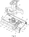
- the figure 2 shows an exploded view of an embodiment of an electrical module 1 according to the invention in the contacting position.
- the contacting element 40 is shown lifted from the rotating element 30, which the dashed line indicates.
- the dashed line also represents the axis of rotation D.
- the rotary element 30 is arranged on the carrier element 50 , the articulated arm 21 being coupled to the rotary element 30 , the articulated arm 21 being formed in particular integrally by the rotary element 30 which is coupled to the actuating arm 10 via the articulated joint 20 .
- the rotating element 30 is coupled to a protruding portion 31 which, in particular, is formed integrally with the rotating element 30 .
- the projection area 31 in this case has a latching element 32 which is formed in particular as a latching lug.
- the latching element 32 is arranged opposite the actuating arm 10 with respect to the axis of rotation D. Furthermore, in the embodiment shown, the latching element 32 is arranged in such a way that a linear movement of the actuating arm 10 results in a circular movement of the latching element 32 .
- the residual element 32 is designed in such a way that in the contacting position it presses the seal 12 into the recess 53 due to the coupling of the rotary element 30 to the actuating arm 10 .
- the carrier element 50 has a resistance element 54 , the latching element 32 interacting with the resistance element 54 .
- the resistance element 54 is in turn designed to lock the contacting element 40 or the rotating element 30 in the contacting position, wherein the resistance element 54 can in particular be designed integrally with the carrier element 50 or can be a spring element or a rubber knob.
- the resistance element 54 is arranged in such a way that during the adjustment process from the open position to the contacting position, ie during the fixing movement, the latching element 32 must pass the resistance element 54 in order to reach the contacting position.
- the resistance element 54 inhibits this first the movement, so that an unintentional adjustment and fixing starting from the open position is prevented.
- the fixing movement is inhibited until a peak or dead center of resistance element 54 is reached, with resistance element 54 supporting the fixing movement once this peak is reached, in particular in such a way that resistance element 54 pushes latching element 32 away, with the rotary movement of the Rotating element 30 is supported.
- the resistance element 54 initially has an inhibiting effect, so that an unintentional adjustment of the contacting element 40 and thus a detachment of the coupling of the electrical module 1 to the mounting rail is prevented. After the apex has been exceeded, the interaction between the latching element 32 and the resistance element 54 promotes the adjustment process, so that the electrical module 1 can be released and removed safely.
- the resistance element 54 is a spring element or a rubber nub.
- the rotating element 30 in FIG figure 2 illustrated embodiment two projections 33, which are arranged in relation to the axis of rotation D opposite to each other.
- the projections 33 are in the open position (not in figure 2 shown) arranged in the groove 55, wherein the projections 33 are designed to hold the rotary element 30 in the open position, so that an unintentional adjustment of the rotary element 30 is prevented.
- the projections 33 are designed to bend slightly when a corresponding amount of force is applied during the fixing movement, so that the fixing movement is made possible, with the respective projections 33 interacting with the respective side wall of the two side walls 51, 52 running parallel to one another, so that the fixing movement friction is inhibited.
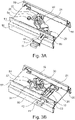
- FIG. 3 shows a side view of an exemplary embodiment of an electrical module 1 according to the invention without Representation of the contacting element 40 in the open position ( Figure 3A ) and in contacting position ( Figure 3B ).
- This shows how the components are adjusted and interact with each other during an adjustment process, with it being shown in particular that actuating the actuating arm 10 by pressing lowers the actuating arm 10 into the electrical module 1, so that the seal 12 is pressed into the recess 53 and this tightly closed.
- the joint 20 is pressed in the direction of the second side wall 52, so that a rotary movement about the axis of rotation D of the rotary element 30 results, with the locking element 32 thereby completing a circular movement and interacting with the resistance element 54, with the rotary element 30 ( and thus also the contacting element 40, not shown, is locked.
- FIGS. 3A and 3B show the projections 33, which cannot be seen in the open position, which are each arranged within the groove 55 of the respective side wall 51, 52 of the electrical module.
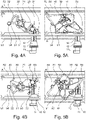
- Figures 4A, 4B, 5A and 5B each show a plan view of an exemplary embodiment of an electrical module 1 according to the invention with ( Figures 5A and 5B ) or without ( Figures 4A and 4B ) Representation of the contacting element 40 both in the open position ( Figures 4A and 5A ) and in contacting position ( Figures 4B and 5B ).
- FIG 6 a further exemplary embodiment of an electrical module 1 according to the invention is shown.
- the carrier element 50 has no resistance element 54 .
- the electrical module 1 designed in this way is also sealed by the seal 12 .
- the projections 33 prevent an unintentional displacement of the rotary element 30 from the open position.
- the set contacting position is fixed by the inserted actuating arm 10 and the joint 20 , with the seal 12 also counteracting a loosening movement of the contacting element 40 or the rotary element 30 by frictional force at the recess 53 .
- the electrical module 1 can serve various and different functions.
- an exemplary embodiment of the electrical module 1 is shown as a lamp, not all components of the electrical module 1 being shown.
- the electrical module 1 is a lamp for room lighting, with the carrier element 50 preferably having at least one light source 55, particularly preferably an LED, and with the lamp in particular having a translucent cover 56 and/or an optical element 57 .
- the individual components are connected to the carrier element 50 without using a separate fixing element, such as a screw or an adhesive, with the individual components being coupled to the carrier element 50 by snap-in connections.
- the translucent cover 59 has a mount for an optical element 57, with the translucent cover 59 also having a carrier plate 56, which can in particular be a circuit board, coupled to the carrier element 50 pressing against the carrier element 50.
- this coupling is preferably formed by a latching connection of the optical element 59 with side walls of the elongate support element 50 that run downward.
- the electrical module 1 can also be designed as a sensor unit or as a camera unit.
- the sensor unit preferably comprises at least one brightness sensor and/or a motion sensor and/or a temperature sensor and/or other sensors.
- the camera unit preferably comprises a camera for room surveillance and/or a conventional camera and/or a night vision camera and/or an infrared camera and/or thermal imaging camera.
- the electrical module 1 can thus be equipped and used in an application-specific manner, with the electrical module 1 being particularly flexibly adaptable to the needs of the user and being used in a variety of ways.
- the electrical module 1 of this type can also be used under adverse conditions such as dust, moisture and moisture, since the seal 12 seals the recess 53 from the outside.
- a mounting rail system can be provided which includes at least one mounting rail and at least one electrical module 1 . It is particularly conceivable that different embodiments of the electrical module 1 are coupled to a mounting rail, so that the mounting rail system can be flexibly and easily adapted to user-specific requirements. Furthermore, such a design of a mounting rail system with the use of at least one electrical module 1 facilitates the assembly of the system and also makes it safer, since the electrical module 1 with the seal 12 enables the system to be operated even under suboptimal conditions, depending on the embodiment a simple, flexible and secure assembly method and simple operation through the joint 20 and/or the latching element 32 and/or the resistance element 54 and/or the projections 33 and/or the engaging elements 41 is achieved.
- an electrical module 1 which is characterized by its simple and safe operation, the recess 53 required for simple and safe operation, through which the actuating arm 10 is guided, through the seal 12 in the mounted state, i.e. in the contacting position, is sealed.
- the concept according to the invention can be used not only for lights, but in principle for all loads or units that are to be connected to corresponding mounting rails.
Landscapes
- Engineering & Computer Science (AREA)
- General Engineering & Computer Science (AREA)
- Connector Housings Or Holding Contact Members (AREA)
Abstract
Description
- Die vorliegende Erfindung betrifft ein elektrisches Modul, welches insbesondere als Leuchte und/oder als Kamera und/oder als Sensoreinheit ausgebildet ist, und mit einer Tragschiene gekoppelt werden kann, wobei die Tragschiene ein Tragschienenprofil mit zwei Seitenwänden sowie mindestens eine in dem Tragschienenprofil angeordnete Stromschiene mit kontaktierbaren Leitungen aufweist.
- Tragschienen mit einem Tragschienenprofil sowie einer in dem Tragschienenprofil gehaltenen Stromschiene sind aus dem Stand der Technik bekannt und werden beispielsweise zum Realisieren länglicher sog. Lichtbandsysteme genutzt. Ein bekanntes Lichtbandsystem wird von der Anmelderin unter der Bezeichnung "TECTON" vertrieben und zeichnet sich dadurch aus, dass Leuchten oder andere elektrische Verbraucher flexibel über die gesamte Länge des Systems hinweg an der Tragschiene positioniert werden können. Ermöglicht wird dies dadurch, dass aufgrund einer speziellen Lagerung der Leitungen der Stromschiene diese über die im Wesentlichen gesamte Länge des Lichtbandsystems hinweg für die Verbraucher zugänglich sind, sodass ein Kontaktieren der Leitungen nicht nur an fest vorgegebenen Positionen, sondern an beliebiger Stelle erfolgen kann. Beispielsweise zeigt die
WO 2001/091250 A1 ein derartiges Lichtbandsystem. - Bei dem oben angesprochenen System "TECTON" sind zwei Stromschienen einander gegenüberliegend an den beiden Seitenwänden eines nach unten offenen, U-förmigen Tragschienenprofils angeordnet. Das Kontaktieren der Leitungen der Stromschienen erfolgt dann dadurch, dass die Leuchte oder der Verbraucher ein drehbares Kontaktierungselement aufweist, welches von der Unterseite her in die Tragschiene eingeführt und anschließend um etwa 45° verdreht wird. An dem Kontaktierungselement angeordnete Kontakte sind hierbei derart ausgeführt, dass sie durch das Verdrehen seitlich ausgeschwenkt werden und letztendlich im verdrehten Zustand die Leitungen der Stromschienen kontaktieren. Mit dem Kontaktierungselement ist weiterhin ein Trägerelement gekoppelt, an welchem wiederum die Leuchtmittel angebracht sind.
- Eine bspw. in der
EP 3 006 819 B1 beschriebene Lösung, sieht hierbei vor, dass das drehbare Kontaktierungselement mit einem Hebel ausgeführt ist, der seitlich durch einen Schlitz des Trägerelements der Leuchte nach außen hervorragt. - Mit den bisher bekannten Realisierungen eines derartigen Tragschienensystems mit einem nach außen geführten Hebel zur Bedienung eines Kontaktierungselements konnte allerdings das Trägerelement der Leuchte oder des Verbrauchers nach außen hin nicht zuverlässig abgedichtet werden, wobei der bisherige nach außen geführte Hebel weiterhin anfällig für ein unbeabsichtigtes Verstellen war.
- Der vorliegenden Erfindung liegt deshalb die Aufgabenstellung zugrunde, ein verbessertes Verstellsystem für das Kontaktierungselement des elektrischen Moduls anzugeben.
- Diese Aufgabe wird durch ein elektrisches Modul mit den Merkmalen des unabhängigen Anspruchs 1 gelöst. Vorteilhafte Weiterbildungen und besondere Ausführungsarten der Erfindung sind in den abhängigen Ansprüchen angegeben.
- Gemäß der Erfindung ist ein elektrisches Modul zum Anschließen an eine Tragschiene, welche ein Tragschienenprofil mit zwei Seitenwänden sowie mindestens eine Stromschiene aufweist, welche an einer der beiden Innenseiten der Seitenwände des Tragschienenprofils angeordnet ist und elektrisch kontaktierbare Leitungen aufweist, vorgesehen. Hierbei weist das elektrische Modul ein Kontaktierungselement auf, welches in das Tragschienenprofil einführbar ist und Anschlusskontakte aufweist, die dazu vorgesehen sind, in einem in das Tragschienenprofil eingesetzten Zustand des Kontaktierungselements in Anlage gegen Leitungen der Stromschiene zu gelangen. Das Kontaktierungselement ist hierbei gegenüber einem Trägerelement des elektrischen Moduls zwischen einer Offenposition, in welcher ein Einführen und Entnehmen des Kontaktierungselements aus dem Tragschienenprofil ermöglicht ist, und einer Kontaktierungsposition, in welcher die Anschlusskontakte Leitungen der Stromschiene kontaktieren, um eine Drehachse drehbar gelagert. Erfindungsgemäß ist zudem vorgesehen, dass das Trägerelement zwei parallel zueinander verlaufende Seitenwände aufweist, wobei das Kontaktierungselement zwischen den beiden parallel zueinander verlaufenden Seitenwänden angeordnet ist, und wobei das Kontaktierungselement mit einem Betätigungsarm gekoppelt ist, welcher dazu ausgebildet ist bei Betätigung das Kontaktierungselement von der Offenposition in die Kontaktierungsposition zu bewegen und vice versa. Weiterhin ist der Betätigungsarm durch eine Ausnehmung in einer der beiden parallel zueinander verlaufenden Seitenwände geführt, derart dass der Betätigungsarm von einer Außenseite des elektrischen Moduls betätigt werden kann. Hierbei weist der Betätigungsarm eine Dichtung auf, welche dazu ausgebildet ist, die Ausnehmung in der Kontaktierungsposition des Kontaktierungselements abzudichten.
- Somit ist ein elektrisches Modul zum Anschluss an eine Tragschiene beschrieben, welches durch Verdrehen des Kontaktierungselements des elektrischen Moduls mit der Tragschiene gekoppelt werden kann. Hierbei ist der Verstellvorgang durch einen nach außen geführten Betätigungsarm komfortabel und einfach von außen für einen Benutzer zu bedienen, wobei zudem im installierten Zustand, also in der Kontaktierungsposition, die Ausnehmung in einer Seitenwand des elektrischen Moduls abgedichtet ist. Dadurch ist ein elektrisches Modul geschaffen, welches auch an feuchten, nassen und/oder staubigen Orten platziert und verwendet werden kann. Das derartige elektrische Modul ist somit wie auch bislang einfach durch Bedienung des Betätigungsarms installierbar, wobei weiterhin allerdings nicht nur eine elektrische und mechanische Kopplung mit der Tragschiene durch die Betätigung des Betätigungsarms erreicht wird, sondern zudem das Trägerelement des elektrischen Moduls an der Ausnehmung abgedichtet ist. Somit ist ein Verstellsystem, bzw. ein Verstellmechanismus angegeben, welcher mehrere Anwendungsschritte in ein simples Bedienen des Betätigungsarms zusammenfasst.
- In einer bevorzugten Ausführungsform dichtet die Dichtung in der Offenposition nicht die Ausnehmung ab.
- Mit einer derartigen Ausführung wird bewerkstelligt, dass der Installationsvorgang, also der Übergang des Kontaktierungselements von der Offenposition in die Kontaktierungsposition, einfach durchführbar ist, wobei möglichst wenig Reibungswiderstand durch die Dichtung entsteht. Somit ist eine Ausführungsform geschaffen, in welcher die Dichtung vorzugsweise fest mit dem Betätigungsarm verbunden ist, sodass die Ausnehmung lediglich in der Kontaktierungsposition vollständig abgedichtet ist. Hierbei lässt sich ein besonders hoher Grad an Dichtigkeit realisieren. Die Dichtung selbst wirkt somit in der Kontaktierungsposition einem versehentlichen Verstellen des Betätigungsarms entgegen. Insbesondere kann vorgesehen sein, dass die Dichtung die Ausnehmung zumindest teilweise umschließt.
- Gemäß einer weiteren Ausführung weist die Dichtung zumindest ein Dichtungselement auf, wobei das Dichtungselement bevorzugt eine Dichtungslamelle ist.
- Eine derartige Ausgestaltung der Dichtung lässt diese die Ausnehmung effektiver vor äußeren Einflüssen wie Staub, Feuchtigkeit und Flüssigkeiten schützen, wobei das zumindest eine Dichtungselement, insbesondere die zumindest eine Dichtungslamelle, die äußeren Einflüsse abschirmt. Besonders bevorzugt weist die Dichtung mehrere Dichtungslamellen auf, wobei jede einzelne Dichtungslamelle mit der Seitenwand, respektive mit den Wänden der Ausnehmung zusammenwirkt, um so das Trägerelement von außen abdichten. Mit zunehmender Anzahl an Lamellen wird hierbei eine Art Labyrinth geschaffen, welches die äußeren Einflussfaktoren abschwächt, sodass die Ausnehmung des Trägerelements stärker abgedichtet ist.
- In einer besonders vorteilhaften Ausführung ist das Kontaktierungselement mit einem Drehelement gekoppelt, wobei das Drehelement bevorzugt über ein Gelenk mit dem Betätigungsarm verbunden ist, derart, dass der Betätigungsarm in einer geradlinigen Bewegung bewegbar ist.
- Hierdurch wird eine besonders einfache und leichtgängige Bedienung des Betätigungsarms ermöglicht, wobei zudem ein versehentliches Verstellen des Betätigungsarms verhindert wird. Der Betätigungsarm kann somit besonders intuitiv durch einen Benutzer bedient werden. Weiterhin wirkt sich eine derartige Ausführung besonders vorteilhaft auf den Verstellvorgang aus, wobei die Dichtung geradlinig in die Ausnehmung eingeführt wird, sodass die Dichtung möglichst dichtend an der Ausnehmung anliegt. Der Betätigungsarm kann dadurch weiterhin besonders platzsparend und stabil gefertigt sein, da beim Betätigen des Betätigungsarms stets aus derselben Richtung eine Kraft wirkt. Die Bewegung des Betätigungsarms ist hierbei bevorzugt derart, dass der Betätigungsarm senkrecht zu einer Längsrichtung des Trägerelements bewegt wird, sodass der Verstellvorgang des Kontaktierungselements durch Hineindrücken bzw. durch Herausziehen des Betätigungsarms erfolgt.
- Weiterhin bevorzugt ist das Gelenk derart ausgebildet, dass eine geradlinige Bewegung des Betätigungsarms in einer Drehbewegung des Drehelements, und des damit gekoppelten Kontaktierungselements, resultiert.
- Mit dieser Ausgestaltung wird bewerkstelligt, dass die erzeugte Drehbewegung nur indirekt durch den Benutzer beeinflusst wird, wobei dies besonders vorteilhaft für die Zuverlässigkeit des Verstellmechanismus ist. Der Bedienung durch den Benutzer ist zudem vereinfacht.
- In einer weiteren Ausführung weist das Drehelement ein Rastelement auf, wobei besonders bevorzugt das Rastelement an einem Vorsprungbereich des Drehelements angeordnet ist.
- Eine derartige Ausgestaltung ist besonders vorteilhaft hinsichtlich der Funktionssicherheit des elektrischen Moduls, da mittels des Rastelements eine bestimmte Stellung des Drehelements, und somit auch des Kontaktierungselements, eingerastet werden kann. Besonders bevorzugt kann mit einem solchen Rastelement die Offenposition und/oder die Kontaktierungsposition fixiert werden, sodass die Kopplung des elektrischen Moduls mit der Tragschiene besonders sicher und einfach ist.
- Besonders bevorzugt resultiert eine geradlinige Bewegung des Betätigungsarms in einer kreisbahnförmigen Bewegung des Rastelements.
- Hierbei wird das Verstellen und Verrasten des Drehelements durch das Rastelement weiter vereinfacht, wobei insbesondere der Benutzer mit geringem Kraftaufwand durch simple lineare Bewegung des Betätigungsarms das Rastelement bewegen kann.
- Gemäß einer weiter bevorzugten Ausführungsform ist das Rastelement derart ausgebildet, dass es in der Kontaktierungsposition durch die Kopplung des Drehelements mit dem Betätigungsarm die Dichtung in die Ausnehmung drückt.
- Hierdurch wird bewerkstelligt, dass in der Kontaktierungsposition durch das Rastelement Kraft auf die Dichtung ausgeübt wird, wobei durch diese Kraft die Dichtung stärker an die Außenwände der Ausnehmung gedrückt wird, sodass effizienter abgedichtet wird.
- Vorzugsweise ist das Rastelement mit Bezug auf die Drehachse dem Betätigungsarm gegenüberliegend angeordnet.
- Somit ist der Verstellmechanismus, besonders kompakt und effizient im Innenraum des Trägerelements anordbar, wobei weiterhin die Bedienung des Betätigungsarms für einen Benutzer erleichtert ist, da im Zusammenspiel mit dem Gelenk ein verringerter Kraftaufwand zum Verstellen des Drehelements und somit des Rastelements benötigt ist.
- Weiterhin bevorzugt weist das Trägerelement ein Widerstandselement auf, welches dazu ausgebildet ist, das Kontaktierungselement in der Kontaktierungsposition zu arretieren, wobei das Widerstandselement insbesondere integral mit dem Trägerelement ausgebildet sein kann oder ein Federelement oder eine Gumminoppe sein kann.
- Es kann also vorgesehen sein, dass das Widerstandselement durch Verformung des Trägerelements gebildet ist. Durch das Widerstandselement wird die Betriebs- und Bedienungssicherheit des elektrischen Moduls verbessert, da die Kontaktierungsposition nicht ohne weiteres, also ohne Krafteinwirkung, zurück in die Offenposition gelangen kann.
- In einer besonders vorteilhaften Ausführung ist das Rastelement dazu ausgebildet, mit dem Widerstandselement zu interagieren, wobei das Rastelement vorzugsweise eine Fixierbewegung des Kontaktierungselements von der Offenposition in die Kontaktierungsposition bis zum Erreichen eines Scheitelpunkts des Widerstandselement die Fixierbewegung hemmt, und wobei ab Erreichen des Scheitelpunkts des Widerstandselements das Rastelement die Fixierbewegung unterstützt, wobei bevorzugt das Rastelement eine Lösebewegung des Kontaktierungselements von der Kontaktierungsposition in die Offenposition bis zum Erreichen eines Scheitelpunkts des Widerstandselements die Lösebewegung hemmt, und wobei ab Erreichen des Scheitelpunkts des Widerstandselements das Rastelement die Lösebewegung unterstützt.
- Somit wird die Bedienbarkeit des elektrischen Moduls, und insbesondere die Bedienbarkeit des Verstellmechanismus, erheblich vereinfacht und zusätzlich gesichert. Weiterhin wird mit dem anfänglichen Hemmen der Lösebewegung erreicht, dass die Dichtung nicht ohne signifikanten Kraftaufwand von der Ausnehmung gelöst wird, sodass die Dichtung des Trägerelements nach außen hin weiter geschützt ist. Zudem wird durch diese Ausführungsform die ordnungsgemäße Installation des elektrischen Moduls, und insbesondere die Fixierbewegung, unterstützt.
- Weiterhin bevorzugt erfüllt die durch die Dichtung abgedichtete Ausnehmung in der Kontaktierungsposition die Schutzklasse IP54, besonders bevorzugt die Schutzklasse IP64.
- Durch Erfüllung dieser Schutzklasse ist das elektrische Modul besonders dafür geeignet, sowohl innerhalb wie auch außerhalb verwendet zu werden. Insbesondere ist gewährleistet, dass das an das Gesamtsystem angeschlossene Modul die Abdichtung des Systems nicht beeinträchtigt, so dass das Tragschienensystem insgesamt die Anforderungen der Schutzklasse IP54 oder sogar IP64 erfüllen kann.
- In einer bevorzugten Ausführung ist das elektrische Modul eine Leuchte ist, wobei bevorzugt das Trägerelement zumindest ein Leuchtmittel, besonders bevorzugt eine LED, aufweist, und wobei insbesondere die Leuchte eine lichtdurchlässige Abdeckung und/oder ein optisches Element aufweist.
- Aufgrund der in der Kontaktierungsposition abgedichteten Ausnehmung kann die Leuchte beispielsweise auch als Feuchtraumleuchte verwendet werden, wobei auch Outdoor-Anwendungen denkbar sind. Weiterhin ist es denkbar neben einer Leuchte zur Nutzbeleuchtung auch Leuchten zur Akzentbeleuchtung, oder Notbeleuchtung einzusetzen. Zudem kann vorgesehen sein, dass die Leuchte eine Rettungs- oder Sicherheitsleuchte, wie beispielsweise eine EXIT-Leuchte zur Notausgangsweisung, ist. Mit einem als Leuchte ausgeführten elektrischen Modul, lässt sich das Trägerelement zusammen mit der Tragschiene in einfacher und schneller Weise als eine Lampe, insbesondere in eine Decken- und/oder Wandlampe, verwenden.
- Gemäß einer weiteren Ausführungsform ist das elektrische Modul eine Sensoreinheit, wobei die Sensoreinheit insbesondere Helligkeitssensoren oder andere Sensoren umfasst.
- Das so beschaffene elektrische Modul kann hierbei durch die Dichtung in Indoor- und Outdoor-Anwendungen als Sensoreinheit dienen, wobei das elektrische Modul beispielsweise Bewegungssensoren, Helligkeitssensoren, Temperatursensoren und/oder andere Sensoren aufweisen kann. Weiterhin kann eine weitere Ausführungsform vorgesehen sein, wobei das elektrische Modul eine Kameraeinheit ist, und wobei die Kameraeinheit insbesondere eine Kamera zur Raumüberwachung oder eine Wärmebildkamera aufweist.
- Somit kann mit dem so beschaffenen elektrischen Modul eine Kameraeinheit sowohl innerhalb geschlossener Räume wie auch außerhalb installiert und verwendet werden, wobei das so beschaffene elektrische Modul auch in ein Überwachungssystem eingebunden werden kann. Insbesondere ist es denkbar, dass das elektrische Modul eine herkömmliche Kamera, und/oder Nachtbildkamera, bzw. eine Infrarotkamera, und/oder eine Wärmebildkamera umfasst.
- Weiterhin kann vorgesehen sein, ein einzelnes elektrisches Modul mit Leuchten, Kameras und/oder Sensoren auszustatten.
- Somit ist ein elektrisches Modul beschrieben, welches besonders flexibel einsetzbar ist, wobei durch die Dichtung die Ausnehmung des Trägerelements im montierten Zustand stets abgedichtet ist. Insbesondere ermöglicht das Kontaktierungselement, dass unabhängig von der Anwendung des elektrischen Moduls die elektrischen Anschlüsse des elektrischen Moduls mit den Leitungen der Tragschiene gekoppelt werden, sodass neben einer reinen Stromversorgung auch eine Datenkommunikation über diese Leitungen denkbar ist. Weiterhin ist unabhängig von der gewählten Ausführung des elektrischen Moduls mit dem Betätigungsarm eine besonders einfache und sichere Montage bzw. Installation des elektrischen Moduls geschaffen. Hierbei wird durch einfaches Betätigen des Betätigungsarms das Kontaktierungselement von der Offenposition in die Kontaktierungsposition bewegt, wobei sowohl eine elektrische Kopplung als auch eine mechanische Kopplung des elektrischen Moduls mit der Tragschiene erzielt wird. In einer bevorzugten Ausführungsform weist das elektrische Modul weiterhin Mechanismen zur Vermeidung eines unabsichtlichen Verstellens des Betätigungsarms auf, wobei zudem die Dichtigkeit des Trägerelements verbessert ist.
- In einer besonders bevorzugten Ausführungsform ist ein Tragschienensystem vorgesehen, wobei das Tragschienensystem zumindest eine Tragschiene, welche ein Tragschienenprofil mit zwei Seitenwänden sowie mindestens eine Stromschiene aufweist, welche an einer der beiden Innenseiten der Seitenwände des Tragschienenprofils angeordnet ist und elektrisch kontaktierbare Leitungen aufweist; sowie zumindest ein elektrisches Modul gemäß einer der zuvor dargelegten Ausführungsformen, umfasst, wobei das zumindest eine elektrische Modul mit der zumindest einen Tragschiene gekoppelt ist.
- Es ist also ein besonders flexibel einsetzbares Tragschienensystem beschrieben, welches in einfacher und schneller Weise an individuelle Anforderungen angepasst werden kann. Weiterhin ist bevorzugt vorgesehen, dass in einem Tragschienensystem mehrere Tragschienen vorhanden sind, welche miteinander gekoppelt sind. In einer bevorzugten Ausführungsform können an einer Tragschiene mehrere elektrische Module installiert werden.
- Somit ist ein elektrisches Modul beschrieben, welches besonders flexibel einsetzbar, leicht, sicher und intuitiv montierbar, und gegen äußere Einflüsse, wie beispielsweise Staub, Feuchtigkeit und Nässe durch eine Dichtung abgedichtet ist. Weiterhin ist ein Tragschienensystem mit zumindest einem elektrischen Modul und zumindest einer Tragschiene angegeben.
- Die Erfindung wird im Folgenden anhand von Ausführungsbeispielen und mit Bezug auf die Zeichnung näher erläutert. Es zeigen:
- Figur 1A
- eine Seitenansicht einer beispielhaften Ausführungsform eines erfindungsgemäßen elektrischen Moduls in Kontaktierungsposition;
- Figur 1B
- eine weitere Seitenansicht einer beispielhaften Ausführungsform eines erfindungsgemäßen elektrischen Moduls in Kontaktierungsposition;
- Figur 1C
- eine Seitenansicht einer beispielhaften Ausführungsform eines erfindungsgemäßen elektrischen Moduls in Offenposition;
- Figur 2
- eine seitliche Explosionsdarstellung einer beispielhaften Ausführungsform eines erfindungsgemäßen elektrischen Moduls in Kontaktierungsposition;
- Figur 3A
- eine Seitenansicht einer beispielhaften Ausfiihrungsform eines erfindungsgemäßen elektrischen Moduls ohne Darstellung des Kontaktierungselements in Offenposition;
- Figur 3B
- eine Seitenansicht einer beispielhaften Ausführungsform eines erfindungsgemäßen elektrischen Moduls ohne Darstellung des Kontaktierungselements in Kontaktierungsposition;
- Figur 4A
- eine Draufsicht auf eine beispielhaften Ausführungsform eines erfindungsgemäßen elektrischen Moduls ohne Darstellung des Kontaktierungselements in Offenposition;
- Figur 4B
- eine Draufsicht auf eine beispielhaften Ausführungsform eines erfindungsgemäßen elektrischen Moduls ohne Darstellung des Kontaktierungselements in Kontaktierungsposition;
- Figur 5A
- eine Draufsicht auf eine beispielhaften Ausführungsform eines erfindungsgemäßen elektrischen Moduls in Offenposition;
- Figur 5B
- eine Draufsicht auf eine beispielhaften Ausführungsform eines erfindungsgemäßen elektrischen Moduls in Kontaktierungsposition;
- Figur 6
- eine Seitenansicht einer weiteren beispielhaften Ausführungsform eines erfindungsgemäßen elektrischen Moduls ohne Darstellung des Kontaktierungselements in Kontaktierungsposition;
- Figur 7
- eine Skizze eines Querschnitts normal zu der Längsachse des Trägerelements einer Ausführungsform eines elektrischen Moduls, wobei das elektrische Modul eine Leuchte ist.
- Die in
Figur 1A gezeigte Ausführungsform eines erfindungsgemäßen elektrischen Moduls 1, welches zum Anschluss an eine (in den Figuren nicht näher dargestellte) Tragschiene vorgesehen ist, weist ein Kontaktierungselement 40 und ein Trägerelement 50 auf, wobei das Kontaktierungselements 40 dazu ausgebildet ist, das elektrische Modul 1 sowohl elektrisch als auch eine mechanisch mit der Tragschiene zu koppeln, wobei das Kontaktierungselement 40 in das Tragschienenprofil einführbar ist und Anschlusskontakte aufweist. Die Tragschiene weist hierbei ein Tragschienenprofil mit zwei Seitenwänden sowie mindestens eine Stromschiene auf, welche an einer der beiden Innenseiten der Seitenwände des Tragschienenprofils angeordnet ist und elektrisch kontaktierbare Leitungen aufweist. Die Anschlusskontakte des Kontaktierungselements 40 sowie die komplette Tragschiene sind nicht in den Figuren dargestellt. Die Anschlusskontakte sind dazu vorgesehen, in einem in das Tragschienenprofil eingesetzten Zustand des Kontaktierungselements 40 in Anlage gegen Leitungen der Stromschiene zu gelangen. Weiterhin ist das Kontaktierungselement 40 gegenüber dem Trägerelement 50 des elektrischen Moduls 1 zwischen einer Offenposition, in welcher ein Einführen und Entnehmen des Kontaktierungselements 40 aus dem Tragschienenprofil ermöglicht ist, und einer Kontaktierungsposition, in welcher die Anschlusskontakte Leitungen der Stromschiene kontaktieren, um eine Drehachse D drehbar gelagert ist. - Das Kontaktierungselement 40 ist zudem mit dem Trägerelement 50 gekoppelt. Das Trägerelement 50 ist bevorzugt länglich ausgebildet, und weist zwei parallel zueinander verlaufende Seitenwände 51, 52 auf, wobei das Kontaktierungselement 40 zwischen den beiden parallel zueinander verlaufenden Seitenwände 51, 52 angeordnet ist. Eine der beiden parallel zueinander verlaufende Seitenwände 51, 52 weist eine Ausnehmung 53 auf, welche es ermöglicht, an der entsprechenden Seite einen Betätigungsarm 10 von einer Innenseite I des elektrischen Moduls 1 zu einer Außenseite A des elektrischen Moduls 1 durchzuführen, sodass der Betätigungsarm 10 von außen für einen Benutzer zugänglich ist und bedient werden kann. Das Kontaktierungselement 40 ist mit dem Betätigungsarm 10 gekoppelt, welcher dazu ausgebildet ist bei Betätigung das Kontaktierungselement 40 von der Offenposition in die Kontaktierungsposition zu bewegen. Ebenso ist der Betätigungsarm 10 dazu ausgebildet das Kontaktierungselement 40 von der Offenposition in die Kontaktierungsposition zu bewegen. Durch die Ausnehmung 53 kann ein Benutzer den Betätigungsarm 10 bequem und intuitiv von der Außenseite A her bedienen, wobei auf der Innenseite /, also im Innenraum des elektrischen Moduls 1 das Kontaktierungselement 40 bewegt wird, da der Betätigungsarm 10 durch die Ausnehmung 53 geführt ist.
- Das Kontaktierungselement 40 ist bevorzugt neben der elektrischen Kopplung mit der Tragschiene auch dazu ausgebildet eine mechanische Kopplung des elektrischen Moduls 1 mit der Tragschiene einzugehen, sodass eine stabile und einfache Montage des elektrischen Moduls 1 ermöglicht ist. Hierbei weist das Kontaktierungselement 40 bevorzugt Eingreifelemente 41 auf, welche in der Kontaktierungsposition in entsprechende Ausbildungen der Tragschiene eingreifen, wobei in der Offenposition das elektrische Modul 1 mitsamt des Kontaktierungselements 40 in einfacher sicherer Weise in die Tragschiene eingeführt werden kann.
- In der in
Figur 1A dargestellten Ausführungsform weist eine erste Seitenwand 51 die Ausnehmung 53 auf, wobei bevorzugt die zweite Seitenwand 52 keine Ausnehmung aufweist. - In die Ausnehmung 53 ist eine Dichtung 12 eingeführt, welche die Ausnehmung 53 von außen her abdichtet. Die Dichtung 12 ist hierbei bevorzugt mit dem Betätigungsarm 10 gekoppelt, wobei insbesondere vorgesehen sein kann, dass der Betätigungsarm 10 starr mit der Dichtung 12 verbunden ist, wobei der Raum zwischen Dichtung 12 und Betätigungsarm 10 besonders gut abgedichtet ist. In der dargestellten Kontaktierungsposition ist die Dichtung 12 in die Ausnehmung 53 eingeführt, wobei in einer bevorzugten Ausführung die Dichtung 12 in der Offenposition nicht in die Ausnehmung 53 eingeführt ist. Dies führt zu einer besonders dichten Abdichtung.
- Der Betätigungsarm 10 weist weiterhin bevorzugt einen Griff 11 auf, wobei der Griff 11 die Bedingung des Betätigungsarms 10 erleichtert und zudem frontal auf den Betätigungsarm 10 auftreffendes Spritzwasser abschirmt, was zu einer verringerten Belastung der Dichtung 12 führt.
- In der dargestellten besonders bevorzugten Ausführung ist der Betätigungsarm 10 mit einem Gelenk 20 gekoppelt, wobei die Bedienung des Betätigungsarms 10 über das Gelenk 20 an das Kontaktierungselement 40 weitergegeben wird. Durch das Gelenk 20 kann die Bauweise des elektrischen Moduls 1 komprimierter gestaltet sein, wobei insbesondere die Fläche des Trägerelements 50 effizienter genutzt wird. Das Gelenk 20 ist hierbei bevorzugt mit einem Drehelement 30 (nicht in
Figur 1A gezeigt) über einen Gelenkarm 21 gekoppelt, wodurch die Drehbewegung des Verstellvorgangs des Kontaktierungselements 40 von Kontaktierungsposition zu Offenposition (und vice versa) effizienter gestaltet ist. - In einer anderen Ausführungsform kann weiterhin auch vorgesehen sein, dass der Betätigungsarm 10 in anderer Weise mit dem Drehelement 30, respektive mit dem Kontaktierungselement 40 gekoppelt ist. Insbesondere kann die Kopplung über ein Getriebe, respektive mittels Zahnräder, implementiert sein.
- Weiterhin kann vorgesehen sein, dass das Trägerelement 50 jeweils an den beiden parallel zueinander verlaufende Seitenwänden 51, 52 eine Nut 55 aufweist, wobei diese Nut 55, respektive Einbuchtung, jeweils dazu ausgebildet sein kann, mit dem Kontaktierungselement 40 und/oder mit dem Drehelement 30 zu interagieren, wobei insbesondere die Kopplung des Kontaktierungselements 40 mit dem Trägerelement 50 verstärkt ist.
- Die
Figur 1B zeigt die in derFigur 1A gezeigte Ausführungsform eines erfindungsgemäßen elektrischen Moduls 1 aus einer weiteren Seitenansicht. Die Dichtung 12 wird nun klarer ersichtlich in der Kontaktierungsposition gezeigt, wobei gezeigt ist, dass die Dichtung 12 nicht nur an der Außenseite A der ersten Seitenwand 52 anliegt, sondern auch auf der Innenseite I der ersten Seitenwand 51 und im Inneren des elektrischen Moduls 1 ausgebildet ist, sodass eine umfassende Dichtung der Ausnehmung 53 vorliegt. - Weiterhin ist ersichtlich, dass in der gezeigten Ausführungsform in der Kontaktierungsposition die Eingreifelemente 41 über den beiden parallel zueinander verlaufende Seitenwänden 51, 52 hervorstehen, sodass im in die Tragschiene eingeführten Zustand eine effektive und stabile Halterung des elektrischen Moduls 1 ermöglicht ist.
- Der Betätigungsarm 10 ist in der Kontaktierungsposition weit in das Innere des elektrischen Moduls 1 versenkt bzw. eingeführt. Somit ist das Gelenk 20 in Richtung der zweiten Seitenwand 52 gedrückt, sodass das Drehelement 30 bzw. das Kontaktierungselement 40 in die Kontaktierungsposition gedreht ist.
- Die
Figur 1C zeigt die in denFiguren 1A und 1B gezeigte Ausführungsform eines erfindungsgemäßen elektrischen Moduls 1 wiederum aus einer anderen Seitenansicht, wobei das elektrische Modul 1 nun in der Offenposition dargestellt ist. - Klar ersichtlich ist, dass in der Offenposition die Dichtung 12 nicht in die Ausnehmung 53 eingeführt ist, wobei die Dichtung 12 mit dem Betätigungsarm 10 gekoppelt ist. Der Betätigungsarm 10 ist nun nur noch minimal im Inneren des elektrischen Moduls 1 vorhanden, sodass das Gelenk 20 maximal in Richtung der ersten Seitenwand 51 gezogen ist und das Drehelement 30 bzw. das Kontaktierungselement 40 in die Offenposition gedreht ist.
- Wie in der
Figur 1C angedeutet ist, weist die Dichtung 12 in einer bevorzugten Ausführungsform zumindest ein Dichtungselement auf, wobei das Dichtungselement bevorzugt eine Dichtungslamelle ist. Hierdurch lässt sich die Ausnehmung 53 besonders gut abdichten. - In der gezeigten Offenposition werden zudem die beiden parallel zueinander verlaufende Seitenwänden 51, 52 nicht durch die Eingreifelemente 41 überlappt, sodass das elektrische Modul 1 in einfacher Weise in eine Tragschiene eingeführt und montiert bzw. aus der Tragschiene entnommen werden kann.
- Der Betätigungsarm 10 ermöglicht es also durch simples Betätigen auf der Außenseite A des elektrischen Moduls 1 die Position des Kontaktierungselements 40 auf der Innenseite I des elektrischen Moduls zu verändern, wobei gleichzeitig durch einen Verstellvorgang hin zur Kontaktierungsposition das elektrische Modul 1 an der Ausnehmung 53 durch die Dichtung 12 abgedichtet wird. In einer bevorzugten Ausführungsform wird der Betätigungsarm 10 in einer geradlinigen Bewegung betätigt, derart dass der Betätigungsarm 10 je nach Verstellvorgang in das elektrische Modul 1 hineingeführt wird, oder herausgezogen wird.
- Hierbei ist der Betätigungsarm 10 bevorzugt derart beschaffen, dass das simple geradlinige Betätigen des Betätigungsarms 10 eine Drehbewegung des Drehelements 30 bzw. des mit dem Drehelement 30 gekoppelten Kontaktierungselement 40 bewirkt. Hierdurch wird einem Benutzer eine besonders intuitive und sichere Bedienmethode zur Verfügung gestellt.
- Die in den Figuren gezeigten Ausführungen des erfindungsgemäßen elektrischen Moduls 1 zeigen stets einen Ausschnitt des bevorzugt länglichen Trägerelements 50, wobei weiterhin auch vorgesehen sein kann, dass ein Trägerelement 50 mehrere Kontaktierungselemente 40, bzw. Drehelemente 30 und somit auch mehrere Betätigungsarme 10 aufweist, wobei dies insbesondere für besonders lange Trägerelemente vorgesehen sein kann. Insbesondere ist die Länge des Trägerelements 50 (und somit die Länge des elektrischen Moduls 1) bevorzugt stets kleiner gleich der Länge der Tragschiene, wobei auch mehrere elektrische Module 1 an einer Tragschiene angeordnet sein können.
- Die
Figur 2 zeigt eine Explosionsdarstellung einer Ausführungsform eines erfindungsgemäßen elektrischen Moduls 1 in Kontaktierungsposition. Hierbei wird das Kontaktierungselement 40 vom Drehelement 30 abgehoben dargestellt, was die gestrichelte Linie verdeutlicht. Insbesondere stellt die gestrichelte Linie auch die Drehachse D dar. - In dieser Darstellung ist die Anordnung auf der Innenseite I des elektrischen Moduls verdeutlicht dargestellt, wobei ersichtlich ist, dass das Kontaktierungselement 40 auf dem Drehelement 30 aufgesteckt gekoppelt ist. Allerdings ist es auch denkbar, dass anstatt der Rastverbindung zwischen dem Kontaktierungselement 40 und dem Drehelement 30 auch eine andersartige Kopplung besteht. Zudem sind in der
Figur 2 die Komponenten, welche unter dem Kontaktierungselement 40 angeordnet sind, dargestellt. - Auf dem Trägerelement 50 ist hierbei das Drehelement 30 angeordnet, wobei mit dem Drehelement 30 der Gelenkarm 21 gekoppelt ist, wobei der Gelenkarm 21 insbesondere integral durch das Drehelement 30 gebildet ist, welcher mit dem Betätigungsarm 10 über das Gelenk 20 gekoppelt ist.
- Weiterhin ist das Drehelement 30 an einen Vorsprungbereich 31 gekoppelt, welcher insbesondere integral mit dem Drehelement 30 ausgebildet ist. Der Vorsprungbereich 31 weist hierbei ein Rastelement 32 auf, welches insbesondere als Rastnase gebildet ist. In der gezeigten Ausführungsform ist das Rastelement 32 mit Bezug auf die Drehachse D dem Betätigungsarm 10 gegenüberliegend angeordnet ist. Weiterhin ist das Rastelement 32 in der gezeigten Ausführung derart angeordnet, dass eine geradlinige Bewegung des Betätigungsarms 10 in einer kreisbahnförmigen Bewegung des Rastelements 32 resultiert.
- Das Restelement 32 ist derart ausgebildet, dass es in der Kontaktierungsposition durch die Kopplung des Drehelements 30 mit dem Betätigungsarm 10 die Dichtung 12 in die Ausnehmung 53 drückt. In der gezeigten Ausführungsform weist hierbei das Trägerelement 50 ein Widerstandselement 54 auf, wobei das Rastelement 32 mit dem Widerstandselement 54 interagiert. Das Widerstandselement 54 ist wiederum dazu ausgebildet, das Kontaktierungselement 40 bzw. das Drehelement 30 in der Kontaktierungsposition zu arretieren, wobei das Widerstandselement 54 insbesondere integral mit dem Trägerelement 50 ausgebildet sein kann oder ein Federelement oder eine Gumminoppe sein kann.
- In der gezeigten Ausführung ist das Widerstandselement 54 derart angeordnet, dass beim Verstellvorgang von Offenposition zu Kontaktierungsposition, also bei der Fixierbewegung das Rastelement 32 das Widerstandselement 54 passieren muss, um die Kontaktierungsposition zu erreichen. Hierbei hemmt das Widerstandselement 54 zunächst die Bewegung, sodass ein unbeabsichtigtes Verstellen und Fixieren ausgehend von der Offenposition verhindert wird. Die Fixierbewegung wird hierbei bis zum Erreichen eines Scheitelpunkts, bzw. eines Totpunkts des Widerstandselements 54 gehemmt, wobei ab Erreichen dieses Scheitelpunkts das Widerstandselement 54 die Fixierbewegung unterstützt, insbesondere derart, dass das Widerstandselement 54 das Rastelement 32 von sich wegdrückt, wobei auch die Drehbewegung des Drehelements 30 unterstützt wird. Hierdurch wird bewerkstelligt, dass der über das Gelenk 20 mit dem Drehelement 30 verbundene Betätigungsarm 10 in das elektrische Modul 1 hereingezogen wird und somit auch die Dichtung 12 in die Ausnehmung 53 gezogen bzw. gedrückt wird, wodurch eine besonders effektive und beständige Dichtung der Ausnehmung 53 realisiert ist.
- Beim Verstellvorgang von Kontaktierungsposition zu Offenposition, also bei der Lösebewegung, wirkt das Widerstandselement 54 zunächst hemmend, sodass ein unbeabsichtigtes Verstellen des Kontaktierungselements 40 und somit ein Lösen der Kopplung des elektrischen Moduls 1 mit der Tragschiene verhindert wird. Nach Überschreitung des Scheitelpunkts wiederum begünstigt das Zusammenspiel aus Rastelement 32 und Widerstandselement 54 den Verstellvorgang, sodass ein gesichertes Lösen und Herausnehmen des elektrischen Moduls 1 bewerkstelligt ist.
- Neben der Ausführung des Widerstandselements 54 als integraler Bestandteil des Trägerelements 50, beispielsweise erzeugt durch Verformen des Trägerelements 50, ist es ebenso denkbar, dass das Widerstandselement 54 ein Federelement oder eine Gumminoppe ist.
- Zudem weist das Drehelement 30 in der in
Figur 2 dargestellten Ausführung zwei Vorsprünge 33 auf, welche in Bezug zur Drehachse D gegenüberliegend zueinander angeordnet sind. Die Vorsprünge 33 sind hierbei in der Offenposition (nicht inFigur 2 dargestellt) in der Nut 55 angeordnet, wobei die Vorsprünge 33 dazu ausgebildet sind das Drehelement 30 in der Offenposition zu halten, sodass ein unbeabsichtigtes Verstellen des Drehelements 30 verhindert wird. Weiterhin sind die Vorsprünge 33 dazu ausgebildet ab einem entsprechenden Kraftaufwand bei der Fixierbewegung sich geringfügig zu verbiegen, sodass die Fixierbewegung ermöglicht ist, wobei die jeweiligen Vorsprünge 33 mit der jeweiligen Seitenwand der beiden parallel zueinander verlaufende Seitenwänden 51, 52 zu interagieren, sodass die Fixierbewegung durch Reibung gehemmt wird. - Die
Figur 3 , bestehend ausFigur 3A und 3B , zeigt eine Seitenansicht einer beispielhaften Ausführungsform eines erfindungsgemäßen elektrischen Moduls 1 ohne Darstellung des Kontaktierungselements 40 in Offenposition (Figur 3A ) und in Kontaktierungsposition (Figur 3B ). Hierbei wird ersichtlich wie die Komponenten während eines Verstellvorgangs verstellt werden und miteinander interagieren, wobei insbesondere dargestellt ist, dass ein Betätigen des Betätigungsarms 10 mittels Drücken den Betätigungsarm 10 in das elektrische Modul 1 versenkt, sodass die Dichtung 12 in die Ausnehmung 53 gedrückt wird und diese dicht verschließt. Weiterhin wird das Gelenk 20 in Richtung der zweiten Seitenwand 52 gedrückt, sodass eine Drehbewegung um die Drehachse D des Drehelements 30 resultiert, wobei hierdurch das Rastelement 32 eine kreisförmige Bewegung vollzeiht und mit dem Widerstandselement 54 interagiert, wobei bei Erreichen der Kontaktierungsposition das Drehelement 30 (und somit auch das nicht gezeigte Kontaktierungselement 40) arretiert ist. - Zudem zeigen die Bilder 3A und 3B die in der Offenposition nicht ersichtlichen Vorsprünge 33, welche jeweils innerhalb der Nut 55 der jeweiligen Seitenwand 51, 52 des elektrischen Moduls angeordnet sind.
- Die
Figuren 4A, 4B, 5A und 5B zeigen jeweils eine Draufsicht auf eine beispielhafte Ausführungsform eines erfindungsgemäßen elektrischen Moduls 1 mit (Figuren 5A und 5B ) bzw. ohne (Figuren 4A und 4B ) Darstellung des Kontaktierungselements 40 sowohl in Offenposition (Figuren 4A und 5A ) sowie in Kontaktierungsposition (Figuren 4B und 5B ). - In den dargestellten Ausführungen wird das Zusammenspiel der Komponenten im Verstellvorgang weiter verdeutlicht. Hierbei ist auch das Abdichten der Ausnehmung 53 durch die Dichtung 12 durch Betätigung des Betätigungsarms 10 dargestellt, wobei ersichtlich ist, dass durch Interaktion des Widerstandselements 54 mit dem Rastelement 32, welches insbesondere mit dem Vorsprungbereich 31 gekoppelt ist, die Position des Drehelements 30, respektive des Kontaktierungselements 40 feststellt und über das Gelenk 20 die Position des Betätigungsarms 10 und somit die Position der Dichtung 12 arretiert ist, derart, dass das elektrische Modul 1 zur Außenseite A hin abgedichtet ist, und insbesondere ein Eintreten von Nässe, Feuchtigkeit und Staub zur Innenseite I hin verhindert wird. In einer bevorzugten Ausführung wird hierbei erreicht, dass diese Abdichtung den Anforderungen der Schutzklasse IP54 genügt, besonders bevorzugt der Schutzklasse IP64.
- Zudem ist die Bewegung der Vorsprünge 33 und der Eingreifelemente 41 durch die
Figuren 4A bis 5B dargestellt. - In der
Figur 6 ist eine weitere beispielhaften Ausführungsform eines erfindungsgemäßen elektrischen Moduls 1 gezeigt. Hierbei weist das Trägerelement 50 kein Widerstandselement 54 auf. Das derartig ausgebildete elektrische Modul 1 ist allerdings ebenfalls durch die Dichtung 12 abgedichtet. Die Vorsprünge 33 verhindern ein unbeabsichtigtes Verstellen des Drehelements 30 aus der Offenposition. Die eingestellte Kontaktierungsposition wird durch den eingeführten Betätigungsarm 10 und das Gelenk 20 fixiert, wobei zudem die Dichtung 12 durch Reibungskraft an der Ausnehmung 53 einer Lösungsbewegung des Kontaktierungselements 40 respektive des Drehelements 30 entgegenwirkt. - Das elektrische Modul 1 kann hierbei verschiedene und unterschiedliche Funktionen bedienen. In der
Figur 7 ist eine beispielhafte Ausführung des elektrischen Moduls 1 als Leuchte gezeigt, wobei nicht alle Komponenten des elektrischen Moduls 1 gezeigt sind. Insbesondere kann vorgesehen sein, dass das elektrische Modul 1 eine Leuchte zur Raumbeleuchtung ist, wobei bevorzugt das Trägerelement 50 zumindest ein Leuchtmittel 55, besonders bevorzugt eine LED, aufweist, und wobei insbesondere die Leuchte eine lichtdurchlässige Abdeckung 56 und/oder ein optisches Element 57 aufweist. Hierbei kann insbesondere vorgesehen sein, dass die einzelnen Komponenten ohne Verwendung eines eigenständigen Fixierelements, wie beispielsweise einer Schraube oder einer Verklebung, mit dem Trägerelement 50 verbunden werden, wobei die einzelnen Komponenten durch Rastverbindungen mit dem Trägerelement 50 gekoppelt sind. Insbesondere kann vorgesehen sein, dass die lichtdurchlässige Abdeckung 59 eine Fassung für ein optisches Element 57 aufweist, wobei zudem die lichtdurchlässige Abdeckung 59 eine Trägerplatte 56, welche insbesondere eine Platine sein kann, gegen das Trägerelement 50 drückend mit dem Trägerelement 50 gekoppelt ist. Diese Kopplung ist hierbei bevorzugt durch eine einrastende Verbindung des optischen Elements 59 mit nach unten geführten Seitenwänden des länglichen Trägerelements 50 gebildet. - Weiterhin kann das elektrische Modul 1 auch als Sensoreinheit oder als Kameraeinheit ausgebildet sein. In der Ausführungsform des elektrischen Moduls 1 als Sensoreinheit, umfasst die Sensoreinheit bevorzugt zumindest einen Helligkeitssensoren und/oder einen Bewegungssensor und/oder einen Temperatursensoren und/oder andere Sensoren. In der Ausführungsform des elektrischen Moduls 1 als Kameraeinheit, umfasst die Kameraeinheit bevorzugt eine Kamera zur Raumüberwachung und/oder eine herkömmliche Kamera und/oder eine Nachtbildkamera und/oder eine Infrarotkamera und/oder Wärmebildkamera.
- Somit kann das elektrische Modul 1 anwendungsspezifisch ausgestattet und eingesetzt werden, wobei das elektrische Modul 1 besonders flexibel an die Bedürfnisse des Benutzers anpassbar ist und vielseitig verwendet werden kann. Insbesondere kann das derartige elektrische Modul 1 auch unter widrigen Bedingungen wie beispielsweise Staub, Feuchtigkeit und Nässe eingesetzt werden, da die Dichtung 12 die Ausnehmung 53 nach außen hin abdichtet.
- Weiterhin kann ein Tragschienensystem vorgesehen sein, welches zumindest eine Tragschiene, sowie zumindest ein elektrisches Modul 1 umfasst. Hierbei ist insbesondere denkbar, dass verschiedene Ausführungsformen des elektrischen Moduls 1 mit einer Tragschiene gekoppelt werden, sodass das Tragschienensystem an benutzerspezifische Anforderungen flexibel und einfach anpassbar ist. Weiterhin wird durch eine derartige Ausgestaltung eines Tragschienensystems mit der Verwendung zumindest eines elektrischen Moduls 1 die Montage des Systems erleichtert und zudem sicherer gemacht, da das elektrische Modul 1 mit der Dichtung 12 den Betrieb des Systems auch unter suboptimalen Bedingungen ermöglicht, wobei zudem je nach Ausführungsform ein einfaches, flexibles und sicheres Montageverfahren und eine einfache Bedienung durch das Gelenk 20 und/oder das Rastelement 32 und/oder das Widerstandselement 54 und/oder die Vorsprünge 33 und/oder die Eingreifelemente 41 erzielt ist.
- Letztendlich wird also durch die erfindungsgemäße Lösung eine sehr einfach zu handhabende, äußerst komfortable und sichere Möglichkeit geschaffen, das Kontaktierungselement eines elektrischen Moduls 1 eines Tragschienensystems zu betätigen. Somit ist ein elektrisches Modul 1 beschrieben, welches sich durch seine einfache und sichere Bedienbarkeit auszeichnet, wobei die zur einfachen und sicheren Bedienung benötigte Ausnehmung 53, durch welche der Betätigungsarm 10 geführt ist, durch die Dichtung 12 im montierten Zustand, also in der Kontaktierungsposition, abgedichtet ist.
- Wie bereits erwähnt kann das erfindungsgemäße Konzept nicht nur bei Leuchten zum Einsatz kommen, sondern grundsätzlich bei allen Verbrauchern oder Einheiten, die an entsprechende Tragschienen anzuschließen sind.
Claims (15)
- Elektrisches Modul (1) zum Anschließen an eine Tragschiene, welche ein Tragschienenprofil mit zwei Seitenwänden sowie mindestens eine Stromschiene aufweist, welche an einer der beiden Innenseiten der Seitenwände des Tragschienenprofils angeordnet ist und elektrisch kontaktierbare Leitungen aufweist, wobei das elektrische Modul (1) ein Kontaktierungselement (40) aufweist, welches in das Tragschienenprofil einführbar ist und Anschlusskontakte aufweist, die dazu vorgesehen sind, in einem in das Tragschienenprofil eingesetzten Zustand des Kontaktierungselements (40) in Anlage gegen Leitungen der Stromschiene zu gelangen,und wobei das Kontaktierungselement (40) gegenüber einem Trägerelement (50) des elektrischen Moduls (1) zwischen einer Offenposition, in welcher ein Einführen und Entnehmen des Kontaktierungselements (40) aus dem Tragschienenprofil ermöglicht ist, und einer Kontaktierungsposition, in welcher die Anschlusskontakte Leitungen der Stromschiene kontaktieren, um eine Drehachse (D) drehbar gelagert ist,wobei das Trägerelement (50) zwei parallel zueinander verlaufenden Seitenwände (51, 52) aufweist, wobei das Kontaktierungselement (40) zwischen den beiden parallel zueinander verlaufenden Seitenwänden (51, 52) angeordnet ist, undwobei das Kontaktierungselement (40) mit einem Betätigungsarm (10) gekoppelt ist, welcher dazu ausgebildet ist bei Betätigung das Kontaktierungselement (40) von der Offenposition in die Kontaktierungsposition zu bewegen und vice versa, undwobei der Betätigungsarm (10) durch eine Ausnehmung (53) in einer der beiden parallel zueinander verlaufenden Seitenwände (51, 52) geführt ist, derart dass der Betätigungsarm (10) von einer Außenseite (A) des elektrischen Moduls (1) betätigt werden kann,dadurch gekennzeichnet,dass der Betätigungsarm (10) eine Dichtung (12) aufweist, welche dazu ausgebildet ist, die Ausnehmung (53) in der Kontaktierungsposition des Kontaktierungselements (40) abzudichten.
- Elektrisches Modul nach Anspruch 1,dadurch gekennzeichnet,dass die Dichtung (12) in der Offenposition nicht die Ausnehmung (53) abdichtet.
- Elektrisches Modul nach einem der Ansprüche 1 oder 2,dadurch gekennzeichnet,dass die Dichtung (12) zumindest ein Dichtungselement aufweist, wobei das Dichtungselement bevorzugt eine Dichtungslamelle ist.
- Elektrisches Modul nach einem der vorherigen Ansprüche,dadurch gekennzeichnet,dass das Kontaktierungselement (40) mit einem Drehelement (30) gekoppelt ist, wobei das Drehelement (30) bevorzugt über ein Gelenk (20) mit dem Betätigungsarm (10) verbunden ist, derart, dass der Betätigungsarm (10) in einer geradlinigen Bewegung bewegbar ist.
- Elektrisches Modul nach Anspruch 4,dadurch gekennzeichnet,dass das Gelenk (20) derart ausgebildet ist, dass eine geradlinige Bewegung des Betätigungsarms (10) in einer Drehbewegung des Drehelements (30), und des damit gekoppelten Kontaktierungselements (40), resultiert.
- Elektrisches Modul nach Anspruch 4 oder 5,dadurch gekennzeichnet,dass das Drehelement (30) ein Rastelement (32) aufweist, wobei besonders bevorzugt das Rastelement (32) an einem Vorsprungbereich (31) des Drehelements (30) angeordnet ist.
- Elektrisches Modul nach einem der Ansprüche Anspruch 4 bis 6,dadurch gekennzeichnet,dass eine geradlinige Bewegung des Betätigungsarms (10) in einer kreisbahnförmigen Bewegung des Rastelements (32) resultiert.
- Elektrisches Modul nach einem der Ansprüche 6 oder 7,dadurch gekennzeichnet,dass das Rastelement (32) derart ausgebildet ist, dass es in der Kontaktierungsposition durch die Kopplung des Drehelements (30) mit dem Betätigungsarm (10) die Dichtung (12) in die Ausnehmung (53) drückt.
- Elektrisches Modul nach einem der Ansprüche 6 bis 8,dadurch gekennzeichnet,dass das Rastelement (32) mit Bezug auf die Drehachse (D) dem Betätigungsarm (10) gegenüberliegend angeordnet ist.
- Elektrisches Modul nach einem der vorherigen Ansprüche,dadurch gekennzeichnet,dass das Trägerelement (50) ein Widerstandselement (54) aufweist, welches dazu ausgebildet ist, das Kontaktierungselement (40) in der Kontaktierungsposition zu arretieren, wobei das Widerstandselement (54) insbesondere integral mit dem Trägerelement (50) ausgebildet sein kann oder ein Federelement oder eine Gumminoppe sein kann.
- Elektrisches Modul nach Anspruch 10,dadurch gekennzeichnet,dass das Rastelement (32) dazu ausgebildet ist, mit dem Widerstandselement (54) zu interagieren,wobei das Rastelement (32) vorzugsweise eine Fixierbewegung des Kontaktierungselements (40) von der Offenposition in die Kontaktierungsposition bis zum Erreichen eines Scheitelpunkts des Widerstandselement (54) die Fixierbewegung hemmt, und wobei ab Erreichen des Scheitelpunkts des Widerstandselements (54) das Rastelement (32) die Fixierbewegung unterstützt,wobei bevorzugt das Rastelement (32) eine Lösebewegung des Kontaktierungselements (40) von der Kontaktierungsposition in die Offenposition bis zum Erreichen eines Scheitelpunkts des Widerstandselements (54) die Lösebewegung hemmt, und wobei ab Erreichen des Scheitelpunkts des Widerstandselements (54) das Rastelement (32) die Lösebewegung unterstützt.
- Elektrisches Modul nach einem der vorherigen Ansprüche,dadurch gekennzeichnet,dass in der Kontaktierungsposition die Abdichtung der Ausnehmung (53) die Schutzklasse IP54, bevorzugt die Schutzklasse IP64 erfüllt.
- Elektrisches Modul nach einem der vorherigen Ansprüche,dadurch gekennzeichnet,dass das elektrische Modul (1) eine Leuchte ist, wobei bevorzugt das Trägerelement (50) zumindest ein Leuchtmittel (55), besonders bevorzugt eine LED, aufweist, und wobei insbesondere die Leuchte eine lichtdurchlässige Abdeckung (56) und/oder ein optisches Element (57) aufweist.
- Elektrisches Modul nach einem der Ansprüche 1 bis 12,dadurch gekennzeichnet,dass das elektrische Modul (1) eine Sensoreinheit ist, wobei die Sensoreinheit insbesondere Helligkeitssensoren oder andere Sensoren umfasst, oderdass das elektrische Modul (1) eine Kameraeinheit ist, wobei die Kameraeinheit insbesondere eine Kamera zur Raumüberwachung oder eine Wärmebildkamera aufweist.
- Tragschienensystem umfassend:- zumindest eine Tragschiene, welche ein Tragschienenprofil mit zwei Seitenwänden sowie mindestens eine Stromschiene aufweist, welche an einer der beiden Innenseiten der Seitenwände des Tragschienenprofils angeordnet ist und elektrisch kontaktierbare Leitungen aufweist; sowie- zumindest ein elektrisches Modul (1) gemäß einem der vorherigen Ansprüche, wobei das zumindest eine elektrische Modul (1) mit der zumindest einen Tragschiene gekoppelt ist.
Applications Claiming Priority (1)
| Application Number | Priority Date | Filing Date | Title |
|---|---|---|---|
| DE102020128275.3A DE102020128275A1 (de) | 2020-10-28 | 2020-10-28 | Elektrisches modul zum anschluss an eine tragschiene |
Publications (2)
| Publication Number | Publication Date |
|---|---|
| EP3992522A1 true EP3992522A1 (de) | 2022-05-04 |
| EP3992522B1 EP3992522B1 (de) | 2022-11-23 |
Family
ID=78413741
Family Applications (1)
| Application Number | Title | Priority Date | Filing Date |
|---|---|---|---|
| EP21204894.6A Active EP3992522B1 (de) | 2020-10-28 | 2021-10-27 | Elektrisches modul zum anschluss an eine tragschiene |
Country Status (3)
| Country | Link |
|---|---|
| EP (1) | EP3992522B1 (de) |
| AT (1) | AT17878U1 (de) |
| DE (1) | DE102020128275A1 (de) |
Cited By (1)
| Publication number | Priority date | Publication date | Assignee | Title |
|---|---|---|---|---|
| DE202022103438U1 (de) | 2022-06-21 | 2023-09-22 | Zumtobel Lighting Gmbh | Elektrisches Modul zum Anschließen an eine Tragschiene und Kontaktierungselement hierfür |
Families Citing this family (5)
| Publication number | Priority date | Publication date | Assignee | Title |
|---|---|---|---|---|
| DE102022204265A1 (de) | 2022-04-29 | 2023-11-02 | H4X E.U. | Adapter zur Verwendung in einem Schienenleuchtensystem, sowie Beleuchtungsanordnung |
| DE102022123241A1 (de) * | 2022-09-13 | 2024-03-14 | Zumtobel Lighting Gmbh | Anschlussstecker für Leuchtentragschienensystem |
| DE102023110848A1 (de) * | 2023-04-27 | 2024-10-31 | Zumtobel Lighting Gmbh | Pendelleuchte |
| WO2025180774A1 (de) * | 2024-03-01 | 2025-09-04 | Zumtobel Lighting Gmbh | Drehbarer halteadapter zur lösbaren elektrischen verbindung und mechanischen halterung in einer dc-stromschiene |
| EP4611191A1 (de) * | 2024-03-01 | 2025-09-03 | Zumtobel Lighting GmbH | Rehbarer halteadapter zur lösbaren elektrischen verbindung und mechanischen halterung in einer dc-stromschiene |
Citations (5)
| Publication number | Priority date | Publication date | Assignee | Title |
|---|---|---|---|---|
| WO2001091250A1 (de) | 2000-05-24 | 2001-11-29 | Zumtobel Staff Gmbh | Stromschienensystem |
| EP2375128A2 (de) * | 2010-04-09 | 2011-10-12 | Zumtobel Lighting GmbH | Leuchte mit LEDs und den LEDs zugeordneten Linsen |
| DE202012100629U1 (de) * | 2012-02-24 | 2013-05-27 | Zumtobel Lighting Gmbh | Balkenleuchte zum mechanischen und elektrischen Anschluss an eine Tragschiene |
| DE202014104800U1 (de) * | 2014-10-07 | 2016-01-11 | Zumtobel Lighting Gmbh | LED-Leuchte mit verstellbarem Halteelement sowie Anordnung zur Lichtabgabe mit einer solchen LED-Leuchte |
| EP3109544A1 (de) * | 2015-06-22 | 2016-12-28 | Siteco Beleuchtungstechnik GmbH | Leuchteneinsatz mit drehriegel |
Family Cites Families (3)
| Publication number | Priority date | Publication date | Assignee | Title |
|---|---|---|---|---|
| FI821643L (fi) * | 1982-05-10 | 1983-11-11 | Nokia Oy Ab | Baer- och stroemmatningsanordning foer lysroersarmatur |
| US10690329B2 (en) * | 2017-01-05 | 2020-06-23 | Modulex Inc. | Power supply box device |
| CN206647872U (zh) * | 2017-04-27 | 2017-11-17 | 宁波港普光电科技有限公司 | 高光效轨道支架灯 |
-
2020
- 2020-10-28 DE DE102020128275.3A patent/DE102020128275A1/de active Pending
-
2021
- 2021-04-23 AT ATGM50085/2021U patent/AT17878U1/de not_active IP Right Cessation
- 2021-10-27 EP EP21204894.6A patent/EP3992522B1/de active Active
Patent Citations (6)
| Publication number | Priority date | Publication date | Assignee | Title |
|---|---|---|---|---|
| WO2001091250A1 (de) | 2000-05-24 | 2001-11-29 | Zumtobel Staff Gmbh | Stromschienensystem |
| EP2375128A2 (de) * | 2010-04-09 | 2011-10-12 | Zumtobel Lighting GmbH | Leuchte mit LEDs und den LEDs zugeordneten Linsen |
| DE202012100629U1 (de) * | 2012-02-24 | 2013-05-27 | Zumtobel Lighting Gmbh | Balkenleuchte zum mechanischen und elektrischen Anschluss an eine Tragschiene |
| DE202014104800U1 (de) * | 2014-10-07 | 2016-01-11 | Zumtobel Lighting Gmbh | LED-Leuchte mit verstellbarem Halteelement sowie Anordnung zur Lichtabgabe mit einer solchen LED-Leuchte |
| EP3006819A1 (de) | 2014-10-07 | 2016-04-13 | Zumtobel Lighting GmbH | Led-leuchte mit verstellbarem halteelement sowie anordnung zur lichtabgabe mit einer solchen led-leuchte |
| EP3109544A1 (de) * | 2015-06-22 | 2016-12-28 | Siteco Beleuchtungstechnik GmbH | Leuchteneinsatz mit drehriegel |
Cited By (1)
| Publication number | Priority date | Publication date | Assignee | Title |
|---|---|---|---|---|
| DE202022103438U1 (de) | 2022-06-21 | 2023-09-22 | Zumtobel Lighting Gmbh | Elektrisches Modul zum Anschließen an eine Tragschiene und Kontaktierungselement hierfür |
Also Published As
| Publication number | Publication date |
|---|---|
| AT17878U1 (de) | 2023-06-15 |
| DE102020128275A1 (de) | 2022-04-28 |
| EP3992522B1 (de) | 2022-11-23 |
Similar Documents
| Publication | Publication Date | Title |
|---|---|---|
| EP3992522B1 (de) | Elektrisches modul zum anschluss an eine tragschiene | |
| EP1646118A2 (de) | Gehäuseanordnung mit mindestens zwei Verbindungsdosen | |
| DE10013111A1 (de) | Adapterplatte und System zur Anbringung eines Bauelementes auf eine Montageunterlage | |
| DE3214528C2 (de) | Vorrichtung zur Festlegung von Instrumentengehäusen in einer Trägerplatte | |
| EP3139454B1 (de) | Elektrisches gerät für die montage im innern eines schaltschranks | |
| WO2021069361A1 (de) | Leuchte oder elektrische einheit zum anschluss an eine tragschiene | |
| EP0686225B1 (de) | Gehäuse zum aufnehmen von elektrischen antrieben | |
| DE20205823U1 (de) | Kupplungsdose | |
| AT18590U1 (de) | Elektrisches Modul zum Anschließen an eine Tragschiene und Kontaktierungselement hierfür | |
| EP1039578A2 (de) | Schalter | |
| DE29806869U1 (de) | Elektrisches Anschlußelement | |
| EP1401070A2 (de) | Einrichtung zur Befestigung eines Installationsgerätes auf einer Tragschiene | |
| DE1901074C3 (de) | Elektrisches Schaltgerät oder Relais | |
| EP2002177B1 (de) | Leuchtenanordnung | |
| EP0735614B1 (de) | Schraubklemme für elektrische Leiter | |
| AT18667U1 (de) | Elektrisches Modul zum Anschließen an eine Tragschiene und Kontaktierungselement hierfür | |
| DE29606735U1 (de) | Verriegelungs- und Entriegelungsvorrichtung für ein Gehäuse | |
| EP4337888B1 (de) | Elektrisches modul zum anschliessen an eine tragschiene | |
| DE102005019245B3 (de) | Optimierte Anschließbarkeit durch axiales Rasten von elektrischen Steckvorrichtungen | |
| BE1032147B1 (de) | Sensor-Aktor-Verteiler | |
| DE10355192B4 (de) | Anschlusselement | |
| EP3879168B1 (de) | Modulares leuchtenset | |
| EP2095383A1 (de) | Staubschutzeinrichtung für ein melde- und/oder befehlsgerät | |
| WO2021160339A1 (de) | Elektrogerät, insbesondere umrichter oder umrichtermotor, mit einem deckelteil und signalelektronik | |
| DE202024100272U1 (de) | Elektrisches Modul zum Anschließen an eine Tragschiene mit einem Tragschienenprofil |
Legal Events
| Date | Code | Title | Description |
|---|---|---|---|
| PUAI | Public reference made under article 153(3) epc to a published international application that has entered the european phase |
Free format text: ORIGINAL CODE: 0009012 |
|
| STAA | Information on the status of an ep patent application or granted ep patent |
Free format text: STATUS: THE APPLICATION HAS BEEN PUBLISHED |
|
| AK | Designated contracting states |
Kind code of ref document: A1 Designated state(s): AL AT BE BG CH CY CZ DE DK EE ES FI FR GB GR HR HU IE IS IT LI LT LU LV MC MK MT NL NO PL PT RO RS SE SI SK SM TR |
|
| STAA | Information on the status of an ep patent application or granted ep patent |
Free format text: STATUS: REQUEST FOR EXAMINATION WAS MADE |
|
| 17P | Request for examination filed |
Effective date: 20220503 |
|
| RBV | Designated contracting states (corrected) |
Designated state(s): AL AT BE BG CH CY CZ DE DK EE ES FI FR GB GR HR HU IE IS IT LI LT LU LV MC MK MT NL NO PL PT RO RS SE SI SK SM TR |
|
| REG | Reference to a national code |
Ref country code: DE Ref legal event code: R079 Ref document number: 502021000266 Country of ref document: DE Free format text: PREVIOUS MAIN CLASS: F21S0004280000 Ipc: F21V0021350000 |
|
| GRAP | Despatch of communication of intention to grant a patent |
Free format text: ORIGINAL CODE: EPIDOSNIGR1 |
|
| STAA | Information on the status of an ep patent application or granted ep patent |
Free format text: STATUS: GRANT OF PATENT IS INTENDED |
|
| RIC1 | Information provided on ipc code assigned before grant |
Ipc: H01R 25/16 20060101ALN20220826BHEP Ipc: H01R 13/52 20060101ALN20220826BHEP Ipc: H02G 3/08 20060101ALI20220826BHEP Ipc: F21Y 115/10 20160101ALI20220826BHEP Ipc: F21V 21/35 20060101AFI20220826BHEP |
|
| GRAS | Grant fee paid |
Free format text: ORIGINAL CODE: EPIDOSNIGR3 |
|
| INTG | Intention to grant announced |
Effective date: 20220922 |
|
| GRAA | (expected) grant |
Free format text: ORIGINAL CODE: 0009210 |
|
| STAA | Information on the status of an ep patent application or granted ep patent |
Free format text: STATUS: THE PATENT HAS BEEN GRANTED |
|
| AK | Designated contracting states |
Kind code of ref document: B1 Designated state(s): AL AT BE BG CH CY CZ DE DK EE ES FI FR GB GR HR HU IE IS IT LI LT LU LV MC MK MT NL NO PL PT RO RS SE SI SK SM TR |
|
| REG | Reference to a national code |
Ref country code: GB Ref legal event code: FG4D Free format text: NOT ENGLISH |
|
| REG | Reference to a national code |
Ref country code: CH Ref legal event code: EP |
|
| REG | Reference to a national code |
Ref country code: DE Ref legal event code: R096 Ref document number: 502021000266 Country of ref document: DE |
|
| REG | Reference to a national code |
Ref country code: AT Ref legal event code: REF Ref document number: 1533335 Country of ref document: AT Kind code of ref document: T Effective date: 20221215 |
|
| REG | Reference to a national code |
Ref country code: IE Ref legal event code: FG4D Free format text: LANGUAGE OF EP DOCUMENT: GERMAN |
|
| REG | Reference to a national code |
Ref country code: LT Ref legal event code: MG9D |
|
| REG | Reference to a national code |
Ref country code: NL Ref legal event code: MP Effective date: 20221123 |
|
| PG25 | Lapsed in a contracting state [announced via postgrant information from national office to epo] |
Ref country code: SE Free format text: LAPSE BECAUSE OF FAILURE TO SUBMIT A TRANSLATION OF THE DESCRIPTION OR TO PAY THE FEE WITHIN THE PRESCRIBED TIME-LIMIT Effective date: 20221123 Ref country code: PT Free format text: LAPSE BECAUSE OF FAILURE TO SUBMIT A TRANSLATION OF THE DESCRIPTION OR TO PAY THE FEE WITHIN THE PRESCRIBED TIME-LIMIT Effective date: 20230323 Ref country code: NO Free format text: LAPSE BECAUSE OF FAILURE TO SUBMIT A TRANSLATION OF THE DESCRIPTION OR TO PAY THE FEE WITHIN THE PRESCRIBED TIME-LIMIT Effective date: 20230223 Ref country code: LT Free format text: LAPSE BECAUSE OF FAILURE TO SUBMIT A TRANSLATION OF THE DESCRIPTION OR TO PAY THE FEE WITHIN THE PRESCRIBED TIME-LIMIT Effective date: 20221123 Ref country code: FI Free format text: LAPSE BECAUSE OF FAILURE TO SUBMIT A TRANSLATION OF THE DESCRIPTION OR TO PAY THE FEE WITHIN THE PRESCRIBED TIME-LIMIT Effective date: 20221123 Ref country code: ES Free format text: LAPSE BECAUSE OF FAILURE TO SUBMIT A TRANSLATION OF THE DESCRIPTION OR TO PAY THE FEE WITHIN THE PRESCRIBED TIME-LIMIT Effective date: 20221123 |
|
| PG25 | Lapsed in a contracting state [announced via postgrant information from national office to epo] |
Ref country code: RS Free format text: LAPSE BECAUSE OF FAILURE TO SUBMIT A TRANSLATION OF THE DESCRIPTION OR TO PAY THE FEE WITHIN THE PRESCRIBED TIME-LIMIT Effective date: 20221123 Ref country code: PL Free format text: LAPSE BECAUSE OF FAILURE TO SUBMIT A TRANSLATION OF THE DESCRIPTION OR TO PAY THE FEE WITHIN THE PRESCRIBED TIME-LIMIT Effective date: 20221123 Ref country code: LV Free format text: LAPSE BECAUSE OF FAILURE TO SUBMIT A TRANSLATION OF THE DESCRIPTION OR TO PAY THE FEE WITHIN THE PRESCRIBED TIME-LIMIT Effective date: 20221123 Ref country code: IS Free format text: LAPSE BECAUSE OF FAILURE TO SUBMIT A TRANSLATION OF THE DESCRIPTION OR TO PAY THE FEE WITHIN THE PRESCRIBED TIME-LIMIT Effective date: 20230323 Ref country code: HR Free format text: LAPSE BECAUSE OF FAILURE TO SUBMIT A TRANSLATION OF THE DESCRIPTION OR TO PAY THE FEE WITHIN THE PRESCRIBED TIME-LIMIT Effective date: 20221123 Ref country code: GR Free format text: LAPSE BECAUSE OF FAILURE TO SUBMIT A TRANSLATION OF THE DESCRIPTION OR TO PAY THE FEE WITHIN THE PRESCRIBED TIME-LIMIT Effective date: 20230224 |
|
| PG25 | Lapsed in a contracting state [announced via postgrant information from national office to epo] |
Ref country code: NL Free format text: LAPSE BECAUSE OF FAILURE TO SUBMIT A TRANSLATION OF THE DESCRIPTION OR TO PAY THE FEE WITHIN THE PRESCRIBED TIME-LIMIT Effective date: 20221123 |
|
| P01 | Opt-out of the competence of the unified patent court (upc) registered |
Effective date: 20230530 |
|
| PG25 | Lapsed in a contracting state [announced via postgrant information from national office to epo] |
Ref country code: SM Free format text: LAPSE BECAUSE OF FAILURE TO SUBMIT A TRANSLATION OF THE DESCRIPTION OR TO PAY THE FEE WITHIN THE PRESCRIBED TIME-LIMIT Effective date: 20221123 Ref country code: RO Free format text: LAPSE BECAUSE OF FAILURE TO SUBMIT A TRANSLATION OF THE DESCRIPTION OR TO PAY THE FEE WITHIN THE PRESCRIBED TIME-LIMIT Effective date: 20221123 Ref country code: EE Free format text: LAPSE BECAUSE OF FAILURE TO SUBMIT A TRANSLATION OF THE DESCRIPTION OR TO PAY THE FEE WITHIN THE PRESCRIBED TIME-LIMIT Effective date: 20221123 Ref country code: DK Free format text: LAPSE BECAUSE OF FAILURE TO SUBMIT A TRANSLATION OF THE DESCRIPTION OR TO PAY THE FEE WITHIN THE PRESCRIBED TIME-LIMIT Effective date: 20221123 Ref country code: CZ Free format text: LAPSE BECAUSE OF FAILURE TO SUBMIT A TRANSLATION OF THE DESCRIPTION OR TO PAY THE FEE WITHIN THE PRESCRIBED TIME-LIMIT Effective date: 20221123 |
|
| REG | Reference to a national code |
Ref country code: DE Ref legal event code: R097 Ref document number: 502021000266 Country of ref document: DE |
|
| PG25 | Lapsed in a contracting state [announced via postgrant information from national office to epo] |
Ref country code: SK Free format text: LAPSE BECAUSE OF FAILURE TO SUBMIT A TRANSLATION OF THE DESCRIPTION OR TO PAY THE FEE WITHIN THE PRESCRIBED TIME-LIMIT Effective date: 20221123 Ref country code: AL Free format text: LAPSE BECAUSE OF FAILURE TO SUBMIT A TRANSLATION OF THE DESCRIPTION OR TO PAY THE FEE WITHIN THE PRESCRIBED TIME-LIMIT Effective date: 20221123 |
|
| PLBE | No opposition filed within time limit |
Free format text: ORIGINAL CODE: 0009261 |
|
| STAA | Information on the status of an ep patent application or granted ep patent |
Free format text: STATUS: NO OPPOSITION FILED WITHIN TIME LIMIT |
|
| 26N | No opposition filed |
Effective date: 20230824 |
|
| PG25 | Lapsed in a contracting state [announced via postgrant information from national office to epo] |
Ref country code: SI Free format text: LAPSE BECAUSE OF FAILURE TO SUBMIT A TRANSLATION OF THE DESCRIPTION OR TO PAY THE FEE WITHIN THE PRESCRIBED TIME-LIMIT Effective date: 20221123 |
|
| PG25 | Lapsed in a contracting state [announced via postgrant information from national office to epo] |
Ref country code: IT Free format text: LAPSE BECAUSE OF FAILURE TO SUBMIT A TRANSLATION OF THE DESCRIPTION OR TO PAY THE FEE WITHIN THE PRESCRIBED TIME-LIMIT Effective date: 20221123 Ref country code: MC Free format text: LAPSE BECAUSE OF FAILURE TO SUBMIT A TRANSLATION OF THE DESCRIPTION OR TO PAY THE FEE WITHIN THE PRESCRIBED TIME-LIMIT Effective date: 20221123 |
|
| REG | Reference to a national code |
Ref country code: BE Ref legal event code: MM Effective date: 20231031 |
|
| PG25 | Lapsed in a contracting state [announced via postgrant information from national office to epo] |
Ref country code: LU Free format text: LAPSE BECAUSE OF NON-PAYMENT OF DUE FEES Effective date: 20231027 |
|
| PG25 | Lapsed in a contracting state [announced via postgrant information from national office to epo] |
Ref country code: LU Free format text: LAPSE BECAUSE OF NON-PAYMENT OF DUE FEES Effective date: 20231027 |
|
| PG25 | Lapsed in a contracting state [announced via postgrant information from national office to epo] |
Ref country code: BE Free format text: LAPSE BECAUSE OF NON-PAYMENT OF DUE FEES Effective date: 20231031 |
|
| PG25 | Lapsed in a contracting state [announced via postgrant information from national office to epo] |
Ref country code: IE Free format text: LAPSE BECAUSE OF NON-PAYMENT OF DUE FEES Effective date: 20231027 |
|
| PG25 | Lapsed in a contracting state [announced via postgrant information from national office to epo] |
Ref country code: IE Free format text: LAPSE BECAUSE OF NON-PAYMENT OF DUE FEES Effective date: 20231027 |
|
| PG25 | Lapsed in a contracting state [announced via postgrant information from national office to epo] |
Ref country code: BG Free format text: LAPSE BECAUSE OF FAILURE TO SUBMIT A TRANSLATION OF THE DESCRIPTION OR TO PAY THE FEE WITHIN THE PRESCRIBED TIME-LIMIT Effective date: 20221123 |
|
| PG25 | Lapsed in a contracting state [announced via postgrant information from national office to epo] |
Ref country code: BG Free format text: LAPSE BECAUSE OF FAILURE TO SUBMIT A TRANSLATION OF THE DESCRIPTION OR TO PAY THE FEE WITHIN THE PRESCRIBED TIME-LIMIT Effective date: 20221123 |
|
| PG25 | Lapsed in a contracting state [announced via postgrant information from national office to epo] |
Ref country code: CY Free format text: LAPSE BECAUSE OF FAILURE TO SUBMIT A TRANSLATION OF THE DESCRIPTION OR TO PAY THE FEE WITHIN THE PRESCRIBED TIME-LIMIT; INVALID AB INITIO Effective date: 20211027 |
|
| REG | Reference to a national code |
Ref country code: CH Ref legal event code: U11 Free format text: ST27 STATUS EVENT CODE: U-0-0-U10-U11 (AS PROVIDED BY THE NATIONAL OFFICE) Effective date: 20251101 |
|
| PG25 | Lapsed in a contracting state [announced via postgrant information from national office to epo] |
Ref country code: TR Free format text: LAPSE BECAUSE OF FAILURE TO SUBMIT A TRANSLATION OF THE DESCRIPTION OR TO PAY THE FEE WITHIN THE PRESCRIBED TIME-LIMIT Effective date: 20221123 |
|
| PGFP | Annual fee paid to national office [announced via postgrant information from national office to epo] |
Ref country code: DE Payment date: 20251028 Year of fee payment: 5 |
|
| PGFP | Annual fee paid to national office [announced via postgrant information from national office to epo] |
Ref country code: GB Payment date: 20251023 Year of fee payment: 5 |
|
| PGFP | Annual fee paid to national office [announced via postgrant information from national office to epo] |
Ref country code: AT Payment date: 20260113 Year of fee payment: 5 |
|
| PGFP | Annual fee paid to national office [announced via postgrant information from national office to epo] |
Ref country code: FR Payment date: 20251027 Year of fee payment: 5 |
|
| PGFP | Annual fee paid to national office [announced via postgrant information from national office to epo] |
Ref country code: CH Payment date: 20251101 Year of fee payment: 5 |
|
| PG25 | Lapsed in a contracting state [announced via postgrant information from national office to epo] |
Ref country code: HU Free format text: LAPSE BECAUSE OF FAILURE TO SUBMIT A TRANSLATION OF THE DESCRIPTION OR TO PAY THE FEE WITHIN THE PRESCRIBED TIME-LIMIT; INVALID AB INITIO Effective date: 20211027 |