EP3990331B1 - Parkverhalten für autonome fahrzeuge - Google Patents
Parkverhalten für autonome fahrzeuge Download PDFInfo
- Publication number
- EP3990331B1 EP3990331B1 EP20851761.5A EP20851761A EP3990331B1 EP 3990331 B1 EP3990331 B1 EP 3990331B1 EP 20851761 A EP20851761 A EP 20851761A EP 3990331 B1 EP3990331 B1 EP 3990331B1
- Authority
- EP
- European Patent Office
- Prior art keywords
- vehicle
- passenger
- reverse
- maneuvering
- determining
- Prior art date
- Legal status (The legal status is an assumption and is not a legal conclusion. Google has not performed a legal analysis and makes no representation as to the accuracy of the status listed.)
- Active
Links
Images





Classifications
-
- G—PHYSICS
- G05—CONTROLLING; REGULATING
- G05D—SYSTEMS FOR CONTROLLING OR REGULATING NON-ELECTRIC VARIABLES
- G05D1/00—Control of position, course, altitude or attitude of land, water, air or space vehicles, e.g. using automatic pilots
- G05D1/0088—Control of position, course, altitude or attitude of land, water, air or space vehicles, e.g. using automatic pilots characterized by the autonomous decision making process, e.g. artificial intelligence, predefined behaviours
-
- B—PERFORMING OPERATIONS; TRANSPORTING
- B60—VEHICLES IN GENERAL
- B60W—CONJOINT CONTROL OF VEHICLE SUB-UNITS OF DIFFERENT TYPE OR DIFFERENT FUNCTION; CONTROL SYSTEMS SPECIALLY ADAPTED FOR HYBRID VEHICLES; ROAD VEHICLE DRIVE CONTROL SYSTEMS FOR PURPOSES NOT RELATED TO THE CONTROL OF A PARTICULAR SUB-UNIT
- B60W60/00—Drive control systems specially adapted for autonomous road vehicles
- B60W60/001—Planning or execution of driving tasks
- B60W60/0025—Planning or execution of driving tasks specially adapted for specific operations
-
- B—PERFORMING OPERATIONS; TRANSPORTING
- B60—VEHICLES IN GENERAL
- B60W—CONJOINT CONTROL OF VEHICLE SUB-UNITS OF DIFFERENT TYPE OR DIFFERENT FUNCTION; CONTROL SYSTEMS SPECIALLY ADAPTED FOR HYBRID VEHICLES; ROAD VEHICLE DRIVE CONTROL SYSTEMS FOR PURPOSES NOT RELATED TO THE CONTROL OF A PARTICULAR SUB-UNIT
- B60W30/00—Purposes of road vehicle drive control systems not related to the control of a particular sub-unit, e.g. of systems using conjoint control of vehicle sub-units
- B60W30/06—Automatic manoeuvring for parking
-
- B—PERFORMING OPERATIONS; TRANSPORTING
- B60—VEHICLES IN GENERAL
- B60W—CONJOINT CONTROL OF VEHICLE SUB-UNITS OF DIFFERENT TYPE OR DIFFERENT FUNCTION; CONTROL SYSTEMS SPECIALLY ADAPTED FOR HYBRID VEHICLES; ROAD VEHICLE DRIVE CONTROL SYSTEMS FOR PURPOSES NOT RELATED TO THE CONTROL OF A PARTICULAR SUB-UNIT
- B60W30/00—Purposes of road vehicle drive control systems not related to the control of a particular sub-unit, e.g. of systems using conjoint control of vehicle sub-units
- B60W30/18—Propelling the vehicle
- B60W30/18009—Propelling the vehicle related to particular drive situations
- B60W30/18036—Reversing
-
- B—PERFORMING OPERATIONS; TRANSPORTING
- B60—VEHICLES IN GENERAL
- B60W—CONJOINT CONTROL OF VEHICLE SUB-UNITS OF DIFFERENT TYPE OR DIFFERENT FUNCTION; CONTROL SYSTEMS SPECIALLY ADAPTED FOR HYBRID VEHICLES; ROAD VEHICLE DRIVE CONTROL SYSTEMS FOR PURPOSES NOT RELATED TO THE CONTROL OF A PARTICULAR SUB-UNIT
- B60W60/00—Drive control systems specially adapted for autonomous road vehicles
-
- B—PERFORMING OPERATIONS; TRANSPORTING
- B60—VEHICLES IN GENERAL
- B60W—CONJOINT CONTROL OF VEHICLE SUB-UNITS OF DIFFERENT TYPE OR DIFFERENT FUNCTION; CONTROL SYSTEMS SPECIALLY ADAPTED FOR HYBRID VEHICLES; ROAD VEHICLE DRIVE CONTROL SYSTEMS FOR PURPOSES NOT RELATED TO THE CONTROL OF A PARTICULAR SUB-UNIT
- B60W60/00—Drive control systems specially adapted for autonomous road vehicles
- B60W60/001—Planning or execution of driving tasks
- B60W60/0025—Planning or execution of driving tasks specially adapted for specific operations
- B60W60/00253—Taxi operations
-
- B—PERFORMING OPERATIONS; TRANSPORTING
- B62—LAND VEHICLES FOR TRAVELLING OTHERWISE THAN ON RAILS
- B62D—MOTOR VEHICLES; TRAILERS
- B62D15/00—Steering not otherwise provided for
- B62D15/02—Steering position indicators ; Steering position determination; Steering aids
-
- B—PERFORMING OPERATIONS; TRANSPORTING
- B62—LAND VEHICLES FOR TRAVELLING OTHERWISE THAN ON RAILS
- B62D—MOTOR VEHICLES; TRAILERS
- B62D15/00—Steering not otherwise provided for
- B62D15/02—Steering position indicators ; Steering position determination; Steering aids
- B62D15/027—Parking aids, e.g. instruction means
- B62D15/0285—Parking performed automatically
-
- B—PERFORMING OPERATIONS; TRANSPORTING
- B62—LAND VEHICLES FOR TRAVELLING OTHERWISE THAN ON RAILS
- B62D—MOTOR VEHICLES; TRAILERS
- B62D6/00—Arrangements for automatically controlling steering depending on driving conditions sensed and responded to, e.g. control circuits
-
- G—PHYSICS
- G05—CONTROLLING; REGULATING
- G05D—SYSTEMS FOR CONTROLLING OR REGULATING NON-ELECTRIC VARIABLES
- G05D1/00—Control of position, course, altitude or attitude of land, water, air or space vehicles, e.g. using automatic pilots
- G05D1/02—Control of position or course in two dimensions
- G05D1/021—Control of position or course in two dimensions specially adapted to land vehicles
-
- G—PHYSICS
- G08—SIGNALLING
- G08G—TRAFFIC CONTROL SYSTEMS
- G08G1/00—Traffic control systems for road vehicles
- G08G1/16—Anti-collision systems
-
- B—PERFORMING OPERATIONS; TRANSPORTING
- B60—VEHICLES IN GENERAL
- B60W—CONJOINT CONTROL OF VEHICLE SUB-UNITS OF DIFFERENT TYPE OR DIFFERENT FUNCTION; CONTROL SYSTEMS SPECIALLY ADAPTED FOR HYBRID VEHICLES; ROAD VEHICLE DRIVE CONTROL SYSTEMS FOR PURPOSES NOT RELATED TO THE CONTROL OF A PARTICULAR SUB-UNIT
- B60W50/00—Details of control systems for road vehicle drive control not related to the control of a particular sub-unit, e.g. process diagnostic or vehicle driver interfaces
- B60W2050/0062—Adapting control system settings
- B60W2050/0075—Automatic parameter input, automatic initialising or calibrating means
-
- B—PERFORMING OPERATIONS; TRANSPORTING
- B60—VEHICLES IN GENERAL
- B60W—CONJOINT CONTROL OF VEHICLE SUB-UNITS OF DIFFERENT TYPE OR DIFFERENT FUNCTION; CONTROL SYSTEMS SPECIALLY ADAPTED FOR HYBRID VEHICLES; ROAD VEHICLE DRIVE CONTROL SYSTEMS FOR PURPOSES NOT RELATED TO THE CONTROL OF A PARTICULAR SUB-UNIT
- B60W2540/00—Input parameters relating to occupants
- B60W2540/041—Potential occupants
-
- B—PERFORMING OPERATIONS; TRANSPORTING
- B60—VEHICLES IN GENERAL
- B60W—CONJOINT CONTROL OF VEHICLE SUB-UNITS OF DIFFERENT TYPE OR DIFFERENT FUNCTION; CONTROL SYSTEMS SPECIALLY ADAPTED FOR HYBRID VEHICLES; ROAD VEHICLE DRIVE CONTROL SYSTEMS FOR PURPOSES NOT RELATED TO THE CONTROL OF A PARTICULAR SUB-UNIT
- B60W2556/00—Input parameters relating to data
- B60W2556/10—Historical data
Definitions
- Autonomous vehicles such as vehicles which do not require a human driver when operating in an autonomous driving mode, may be used to aid in the transport of passengers or items from one location to another.
- an autonomous vehicle which may not have a driver, is preparing to pull over in order to pick up a passenger certain parking maneuvers, such as parallel parking (involving pulling alongside of a parking spot and reversing into that parking spot) can be difficult and sometimes dangerous maneuvers. For example, it can take quite a long time to complete a parallel parking maneuver, during which a passenger may unknowingly attempt to enter the vehicle before the vehicle is fully parked creating a possibly uncomfortable situation.
- the vehicle's computing devices may not be able to pick up on social cues from drivers of other nearby vehicles who may pull very close behind the vehicle or who may try to pull into the same spot without reversing. In some instances, this can be avoided by always attempting to find very long pullover locations from which the vehicle never has to use a parallel parking maneuver or to reverse in order to pull out. Of course, this may not always be possible and may result in a vehicle making one or more loops "around the block" before being able to pull over and wait for a passenger.
- US2019/66003 A1 discloses systems and methods for confirming the identity of a passenger and changing destination of a vehicle. This may include receiving dispatching instructions to pick up a first passenger at a pickup location and to drop off the first passenger at a first destination as well as authentication information for authenticating a first client computing device of the first passenger. Once the client device is authenticated and a second passenger enters the vehicle, the vehicle is maneuvered towards the first destination. While doing so, a location of the vehicle is compared to location information received from the client computing devices. A notification is sent to a dispatching server based on the comparison and a second destination location is received in response. The vehicle is then maneuvered towards the second destination instead of the first destination.
- CN 109455180 A discloses a method and device for controlling an unmanned vehicle.
- the method particularly comprises the steps that in response to determining that a pedestrian exists in a first target area, behavior prompt information prompting the pedestrian to perform a corresponding behavior is sent; according to the acquired behavior information of the pedestrian, it is determined whether or not the behavior information meets a deceleration condition matched with the prompt information; in response to determining that the deceleration condition is met and determining that the speed of the unmanned vehicle is greater than a preset deceleration threshold, control information used for reducing the moving speed of the unmanned vehicle is transmitted.
- the method achieves the deceleration control of the unmanned vehicle in response to the pedestrian's response to the behavioral prompt information.
- One aspect provides a method of maneuvering a vehicle having an autonomous driving mode.
- the method includes identifying, by one or more processors, a pullover location for the vehicle to stop and wait for a passenger; maneuvering, by the one or more processors, the vehicle in the autonomous driving mode in order to pull over by pulling forward into the pullover location; determining, by the one or more processors, whether to maneuver the vehicle in reverse in the pullover location before or after the passenger enters the vehicle based on context for the pull over with respect to the passenger; and maneuvering, by the one or more processors, the vehicle in the autonomous driving mode in reverse based on the determination of whether to maneuver the vehicle in reverse in the pullover location before or after the passenger enters the vehicle.
- the method also includes, when maneuvering the vehicle in order to pull over by pulling forward into the pullover location, adjusting a minimum distance for the vehicle with respect to other objects in order to maneuver the vehicle within the adjusted minimum distance of another object in front of the vehicle.
- the method also includes the context by determining that a pedestrian is within a predetermined threshold distance of the pullover location, and wherein maneuvering the vehicle in reverse includes maneuvering the vehicle in reverse after the passenger enters the vehicle.
- the method also includes determining the context by determining that no pedestrian is within a predetermined threshold distance of the pullover location, and wherein maneuvering the vehicle in reverse includes maneuvering the vehicle in reverse before the passenger enters the vehicle.
- the method also includes determining the context by determining an expected amount of time for the passenger to reach the vehicle once the vehicle is ready to be maneuvered in reverse in the pullover location, and comparing the expected amount of time to a threshold value.
- the determination of whether to maneuver the vehicle in reverse in the pullover location before or after the passenger enters the vehicle is further based on the comparison.
- maneuvering the vehicle in reverse includes maneuvering the vehicle in reverse before the passenger enters the vehicle when the comparison indicates that the expected amount of time is greater than the threshold value.
- maneuvering the vehicle in reverse includes maneuvering the vehicle in reverse after the passenger enters the vehicle when the comparison indicates that the expected amount of time is less than the threshold value.
- determining the expected amount of time is based on location information for a client computing device associated with the passenger. In this example, determining the expected amount of time is further based on a predetermined walking speed for pedestrians. In addition or alternatively, determining the expected amount of time is based on historical data indicating how long it has taken the passenger to reach one or more vehicles for a pick up in the past. In addition or alternatively, determining the expected amount of time is based on historical data indicating an expected amount of time for passengers to reach one or more vehicles for a pick up. In addition or alternatively, determining the expected amount of time is based on historical data indicating an expected amount of time for passengers to reach one or more vehicles for a pick up at a predetermined time of day.
- determining the expected amount of time is based on historical data indicating an expected amount of time for passengers to reach one or more vehicles for a pick up on a predetermined day of the week. In addition or alternatively, determining the expected amount of time is based on historical data indicating an expected amount of time for passengers to reach one or more vehicles for a pick up at the pullover location. In addition or alternatively, determining the expected amount of time is based on historical data indicating an expected amount of time for passengers to reach one or more vehicles for a pick up at a geographic region including the pullover location and one or more additional pullover locations.
- the method also includes determining the context by determining that a pedestrian who is making progress towards the vehicle is within a predetermined distance of the pullover location, and wherein maneuvering the vehicle in reverse includes maneuvering the vehicle in reverse after the passenger enters the vehicle.
- the method also includes determining the context by determining that no pedestrian who is making progress towards the vehicle is within a predetermined distance of the pullover location, and wherein maneuvering the vehicle in reverse includes maneuvering the vehicle in reverse after the passenger enters the vehicle.
- the method also includes determining the context by determining that a communication link has been established between one or more computing devices of the vehicle and a client computing device associated with the passenger, and wherein maneuvering the vehicle in reverse includes maneuvering the vehicle in reverse after the passenger enters the vehicle.
- the method also includes determining the context by determining that no communication link has been established between one or more computing devices of the vehicle and a client computing device associated with the passenger, and wherein maneuvering the vehicle in reverse includes maneuvering the vehicle in reverse before the passenger enters the vehicle.
- the method also includes determining the context by determining that location information for a client computing device associated with the passenger is within a predetermined threshold distance of the vehicle, and wherein maneuvering the vehicle in reverse includes maneuvering the vehicle in reverse after the passenger enters the vehicle.
- the method also includes determining the context by determining that location information for a client computing device associated with the passenger is not within a predetermined threshold distance of the vehicle, and wherein maneuvering the vehicle in reverse includes maneuvering the vehicle in reverse before the passenger enters the vehicle.
- the method also includes maneuvering the vehicle in reverse includes maneuvering the vehicle in reverse before the passenger enters the vehicle, and the method further comprises providing a notification to indicate to the passenger that the passenger should wait for the vehicle to complete a reversing maneuver before attempting entering the vehicle.
- the technology relates to parking behaviors for autonomous vehicles. For instance, when an autonomous vehicle, which may not have a driver, is preparing to pull over in order to pick up a passenger certain parking maneuvers, such as parallel parking (involving pulling alongside of a parking spot and reversing into that parking spot) can be difficult and sometimes dangerous maneuvers. For example, it can take quite a long time to complete a parallel parking maneuver, during which a passenger may unknowingly attempt to enter the vehicle before the vehicle is fully parked creating a possibly uncomfortable situation.
- the vehicle's computing devices may not be able to pick up on social cues from drivers of other nearby vehicles who may pull very close behind the vehicle or who may try to pull into the same spot without reversing.
- this can be avoided by always attempting to find very long pullover locations from which the vehicle never has to use a parallel parking maneuver or to reverse in order to pull out.
- this may not always be possible and may result in a vehicle making one or more loops "around the block" before being able to pull over and wait for a passenger.
- other driving behaviors may be implemented.
- the vehicle's computing devices may first identify a place to pull over. This may include identifying an area where the vehicle is permitted to park, for instance by identifying a set of predetermined pullover locations in pre-stored map information or by identifying a possible spot by searching for an area on a side of a road long enough for the vehicle to pull forward into and stop. Of these set of predetermined pullover locations and/or possible pullover locations, the vehicle's computing devices may select an available pullover location.
- the vehicle's planning system may implement pull over behavior. This may involve pulling forward into the identified pullover location and stopping the vehicle. In some instances, this may require that the vehicle reverse (i.e. back up) before being able to pull out of the identified pullover location.
- the vehicle's computing devices may determine whether the vehicle should immediately reverse in order to create a gap between the vehicle and another object.
- the vehicle's computing devices may determine context for the pull over with respect to the passenger for the vehicle. For instance, this context may indicate, among other things, whether the actual passenger (i.e. an assigned passenger) or a potential passenger (i.e. a pedestrian who may be the passenger) is nearby. Based on this context, the vehicle's computing devices should wait for the passenger to enter the vehicle before maneuvering the vehicle in reverse. If the context indicates that the actual passenger or a potential passenger is not nearby the vehicle, the vehicle's computing devices may maneuver the vehicle in reverse before the passenger enters the vehicle. This may include reversing away from an object in front of the vehicle.
- determining the context may include determining an expected amount of time for the passenger to reach or arrive at the vehicle. In addition or alternatively, determining the context may include determining whether there are any pedestrians nearby. In addition or alternatively, determining the context may include determining whether there are any pedestrians who are actively making progress towards the vehicle. In addition or alternatively, determining the context may include determining whether the vehicle's computing devices have established communications with and/or authenticated a client computing device associated with the passenger. In addition or alternatively, determining the context may include determining whether location information for a client computing device of the passenger indicates that the passenger is nearby the vehicle.
- the features described herein may enable an autonomous vehicle to implement specific parking behaviors. As noted above, these parking behaviors may improve the ability for the computing devices of a vehicle having an autonomous driving mode to find available pullover locations while doing so safely and avoiding parallel parking maneuvers. In other words, because the vehicle is able to find smaller parking locations (for instance, a 5.1-5.2 meter long van may be able to pull over in an 8 to 10 meter pullover location as opposed to a 15 or more meter pullover location), the vehicle may be more likely to find a pullover location to wait for a passenger and less likely to have to loop around one or more times before doing so.
- these parking behaviors may improve the ability for the computing devices of a vehicle having an autonomous driving mode to find available pullover locations while doing so safely and avoiding parallel parking maneuvers.
- the vehicle may be more likely to find a pullover location to wait for a passenger and less likely to have to loop around one or more times before doing so.
- timing of when a vehicle reverses in a pullover location is dependent upon the context for the pull over with respect to a potential or actual passenger for the vehicle, this may avoid situations in which the vehicle stops and an unknowing passenger attempts to enter the vehicle just before or while the vehicle is reversing, which again can be dangerous for the passenger.
- a vehicle 100 in accordance with one aspect of the disclosure includes various components. While certain aspects of the disclosure are particularly useful in connection with specific types of vehicles, the vehicle may be any type of vehicle including, but not limited to, cars, trucks, motorcycles, buses, recreational vehicles, etc.
- the vehicle may have one or more computing devices, such as computing device 110 containing one or more processors 120, memory 130 and other components typically present in general purpose computing devices.
- the memory 130 stores information accessible by the one or more processors 120, including instructions 134 and data 132 that may be executed or otherwise used by the processor 120.
- the memory 130 may be of any type capable of storing information accessible by the processor, including a computing device-readable medium, or other medium that stores data that may be read with the aid of an electronic device, such as a hard-drive, memory card, ROM, RAM, DVD or other optical disks, as well as other write-capable and read-only memories.
- Systems and methods may include different combinations of the foregoing, whereby different portions of the instructions and data are stored on different types of media.
- the instructions 134 may be any set of instructions to be executed directly (such as machine code) or indirectly (such as scripts) by the processor.
- the instructions may be stored as computing device code on the computing device-readable medium.
- the terms "instructions” and “programs” may be used interchangeably herein.
- the instructions may be stored in object code format for direct processing by the processor, or in any other computing device language including scripts or collections of independent source code modules that are interpreted on demand or compiled in advance. Functions, methods and routines of the instructions are explained in more detail below.
- the data 132 may be retrieved, stored or modified by processor 120 in accordance with the instructions 134.
- the data may be stored in computing device registers, in a relational database as a table having a plurality of different fields and records, XML documents or flat files.
- the data may also be formatted in any computing device-readable format.
- the one or more processor 120 may be any conventional processors, such as commercially available CPUs or GPUs. Alternatively, the one or more processors may be a dedicated device such as an ASIC or other hardware-based processor.
- FIGURE 1 functionally illustrates the processor, memory, and other elements of computing device 110 as being within the same block, it will be understood by those of ordinary skill in the art that the processor, computing device, or memory may actually include multiple processors, computing devices, or memories that may or may not be stored within the same physical housing.
- memory may be a hard drive or other storage media located in a housing different from that of computing device 110. Accordingly, references to a processor or computing device will be understood to include references to a collection of processors or computing devices or memories that may or may not operate in parallel.
- the computing devices 110 may be part of an autonomous control system capable of communicating with various components of the vehicle in order to control the vehicle in an autonomous driving mode.
- the computing devices 110 may be in communication with various systems of vehicle 100, such as deceleration system 160, acceleration system 162, steering system 164, routing system 166, planning system 168, positioning system 170, and perception system 172 in order to control the movement, speed, etc. of vehicle 100 in accordance with the instructions 134 of memory 130 in the autonomous driving mode.
- computing devices 110 may interact with deceleration system 160 and acceleration system 162 in order to control the speed of the vehicle.
- steering system 164 may be used by computing devices 110 in order to control the direction of vehicle 100.
- vehicle 100 is configured for use on a road, such as a car or truck, the steering system may include components to control the angle of wheels to turn the vehicle.
- Routing system 166 may be used by the computing devices 110 in order to generate a route to a destination.
- planning system 168 may be used by computing device 110 in order to follow the route.
- the planning system 168 and/or routing system 166 may store detailed map information, e.g., highly detailed maps identifying the shape and elevation of roadways, lane lines, intersections, crosswalks, speed limits, traffic signals, buildings, signs, real time traffic information, pull over spots vegetation, or other such objects and information.
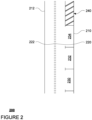
- FIGURE 2 is an example of map information 200 for a section of roadway including.
- the map information 200 may be a local version of the map information stored in the memory 130 of the computing devices 110.
- the map information 200 includes information identifying the shape, location, and other characteristics of curbs 210, 212, lane lines 220, 222, parking spots 230, 232, 234, as well as loading zone 240. Only a few such features are depicted in FIGURE 2 , however, the map information 200 may include significantly more features and details in order to enable the vehicle 100 to be controlled in the autonomous driving mode.
- the map information is depicted herein as an image-based map, the map information need not be entirely image based (for example, raster).
- the map information may include one or more roadgraphs or graph networks of information such as roads, lanes, intersections, and the connections between these features which may be represented by road segments.
- Each feature may be stored as graph data and may be associated with information such as a geographic location and whether or not it is linked to other related features, for example, a stop sign may be linked to a road and an intersection, etc.
- the associated data may include grid-based indices of a roadgraph to allow for efficient lookup of certain roadgraph features.
- Positioning system 170 may be used by computing devices 110 in order to determine the vehicle's relative or absolute position on a map or on the earth.
- the position system 170 may include a GPS receiver to determine the device's latitude, longitude and/or altitude position.
- Other location systems such as laser-based localization systems, inertial-aided GPS, or camera-based localization may also be used to identify the location of the vehicle.
- the location of the vehicle may include an absolute geographical location, such as latitude, longitude, and altitude as well as relative location information, such as location relative to other cars immediately around it which can often be determined with less noise that absolute geographical location.
- the positioning system 170 may also include other devices in communication with the computing devices of the computing devices 110, such as an accelerometer, gyroscope or another direction/speed detection device to determine the direction and speed of the vehicle or changes thereto.
- an acceleration device may determine its pitch, yaw or roll (or changes thereto) relative to the direction of gravity or a plane perpendicular thereto.
- the device may also track increases or decreases in speed and the direction of such changes.
- the device's provision of location and orientation data as set forth herein may be provided automatically to the computing device 110, other computing devices and combinations of the foregoing.
- the perception system 172 also includes one or more components for detecting objects external to the vehicle such as other vehicles, obstacles in the roadway, traffic signals, signs, trees, etc.
- the perception system 172 may include lasers, sonar, radar, cameras and/or any other detection devices that record data which may be processed by the computing devices of the computing devices 110.
- the minivan may include a laser or other sensors mounted on the roof or other convenient location.
- FIGURE 3 is an example external view of vehicle 100.
- roof-top housing 310 and dome housing 312 may include a LIDAR sensor as well as various cameras and radar units.
- housing 320 located at the front end of vehicle 100 and housings 330, 332 on the driver's and passenger's sides of the vehicle may each store a LIDAR sensor.
- housing 330 is located in front of driver door 360.
- Vehicle 100 also includes housings 340, 342 for radar units and/or cameras also located on the roof of vehicle 100. Additional radar units and cameras (not shown) may be located at the front and rear ends of vehicle 100 and/or on other positions along the roof or roof-top housing 310.
- FIGURE 3 also depicts left and right turn signals 112, 114. In this example, front left turn signal 112A, rear left turn signal 112B, and front right turn signal 114A are depicted, but a right rear turn signal is not visible from the perspective of FIGURE 3 .
- the computing devices 110 may be capable of communicating with various components of the vehicle in order to control the movement of vehicle 100 according to primary vehicle control code of memory of the computing devices 110.
- the computing devices 110 may include various computing devices in communication with various systems of vehicle 100, such as deceleration system 160, acceleration system 162, steering system 164, routing system 166, planning system 168, positioning system 170, perception system 172, and power system 174 (i.e. the vehicle's engine or motor) in order to control the movement, speed, etc. of vehicle 100 in accordance with the instructions 134 of memory 130.
- the various systems of the vehicle may function using autonomous vehicle control software in order to determine how to and to control the vehicle.
- a perception system software module of the perception system 172 may use sensor data generated by one or more sensors of an autonomous vehicle, such as cameras, LIDAR sensors, radar units, sonar units, etc., to detect and identify objects and their characteristics. These characteristics may include location, type, heading, orientation, speed, acceleration, change in acceleration, size, shape, etc. In some instances, characteristics may be input into a behavior prediction system software module which uses various behavior models based on object type to output a predicted future behavior for a detected object.
- the characteristics may be put into one or more detection system software modules, such as a traffic light detection system software module configured to detect the states of known traffic signals, construction zone detection system software module configured to detect construction zones from sensor data generated by the one or more sensors of the vehicle as well as an emergency vehicle detection system configured to detect emergency vehicles from sensor data generated by sensors of the vehicle.
- detection system software modules may uses various models to output a likelihood of a construction zone or an object being an emergency vehicle.
- Detected objects, predicted future behaviors, various likelihoods from detection system software modules, the map information identifying the vehicle's environment, position information from the positioning system 170 identifying the location and orientation of the vehicle, a destination for the vehicle as well as feedback from various other systems of the vehicle may be input into a planning system software module of the planning system 168.
- the planning system may use this input to generate trajectories for the vehicle to follow for some brief period of time into the future based on a route generated by a routing module of the routing system 166.
- a control system software module of the computing devices 110 may be configured to control movement of the vehicle, for instance by controlling braking, acceleration and steering of the vehicle, in order to follow a trajectory.
- the computing devices 110 may control the vehicle in an autonomous driving mode by controlling various components. For instance, by way of example, the computing devices 110 may navigate the vehicle to a destination location completely autonomously using data from the detailed map information and planning system 168. The computing devices 110 may use the positioning system 170 to determine the vehicle's location and perception system 172 to detect and respond to objects when needed to reach the location safely.
- computing device 110 may generate trajectories and cause the vehicle to follow these trajectories, for instance, by causing the vehicle to accelerate (e.g., by supplying fuel or other energy to the engine or power system 174 by acceleration system 162), decelerate (e.g., by decreasing the fuel supplied to the engine or power system 174, changing gears, and/or by applying brakes by deceleration system 160), change direction (e.g., by turning the front or rear wheels of vehicle 100 by steering system 164), and signal such changes (e.g., by lighting turn signals 112 or 114 of the signaling system).
- accelerate e.g., by supplying fuel or other energy to the engine or power system 174 by acceleration system 162
- decelerate e.g., by decreasing the fuel supplied to the engine or power system 174, changing gears, and/or by applying brakes by deceleration system 160
- change direction e.g., by turning the front or rear wheels of vehicle 100 by steering system 164
- acceleration system 162 and deceleration system 160 may be a part of a drivetrain that includes various components between an engine of the vehicle and the wheels of the vehicle. Again, by controlling these systems, computing devices 110 may also control the drivetrain of the vehicle in order to maneuver the vehicle autonomously.
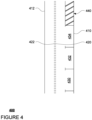
- FIGURE 4 is an example representation of a section of roadway 400 corresponding to the map information 200.
- the shape, location, and other characteristics of curbs 410, 412 may correspond to curbs 210, 212
- lane lines 420, 422 may correspond to lane lines 220, 222
- parking spots 430, 432, 434 may correspond to parking spots 230, 232, 234, and loading zone 440 may correspond to loading zone 240.
- FIGURE 5 is an example representation of vehicle 100 on the section of roadway 400 approaching a pickup location represented by the location marker 510.
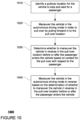
- FIGURE 10 is an example flow diagram 1000 in accordance with aspects of the disclosure which may be performed by one or more processors of one or more computing devices, such as processors 120 of computing devices 110, in order to maneuver a vehicle having an autonomous driving mode.
- a pullover location for the vehicle to stop and wait for a passenger is identified.
- the computing devices 110 may first identify a place for vehicle 100 to pull over.
- This may include identifying an area where the vehicle is permitted to park, for instance by identifying a set of predetermined pullover locations in the map information 200, such as parking spots 230, 232, 234 of FIGURE 2 , or by identifying a possible pullover location by searching for an area on a side of a road long enough for the vehicle to pull forward into and stop.
- the computing devices 110 may also identify loading zone 240 as a possible pullover location either based on the map information 200 or by determining that the area of the loading zone 440 is large enough for vehicle 100 to safely park.
- the computing devices 110 may identify or select an available pullover location where the pullover location is available and still wide enough (i.e. not partially occupied) such that the vehicle is able to pull into the pullover location. For instance, returning to FIGURE 5 , the computing devices may determine that parking spots 430 and 434 (or parking spots 230 and 234) are occupied, here by vehicles 520 and 530, respectively. In this regard, the computing devices 110 may identify parking spot 230 (or parking spot 232) and in some instances, loading zone 440 (or loading zone 240) as available. The computing devices 110 may then select from loading zone 440 and parking spot 430. In this example, it may be preferable to identify or select parking spot 430 as the vehicle 100 may be able to wait longer for a passenger in parking spot 430 than in loading zone 440, even though the loading zone 440 is closed to the location of the location marker 510.
- the vehicle is maneuvered in the autonomous driving mode in order to pull over and pull forward into the pullover location.
- the vehicle's planning system may implement pull over behavior. This may involve the computing devices 110 maneuvering vehicle 100 autonomously in order to cause the vehicle to pull forward into the identified pullover location and stopping the vehicle 100. For instance, turning to FIGURE 6 , the computing devices 110 may use the planning system 168 to generate trajectory 610. Thereafter, the computing devices 110 may control the vehicle 100 in order to follow the trajectory 610 as described above.
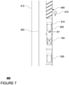
- FIGURE 7 represents the vehicle 100 after it has pulled into the identified pullover location (here parking spot 432).
- the computing devices 110 may always attempt to maintain a minimum distance between the vehicle 100 and other road users. For example, when coming to a stop at a traffic intersection, the vehicle 100 may always stop at least 2 meters or more or less behind another stopped vehicle. However, when pulling into an identified pullover location, the pull over behavior may cause this minimum distance to be adjusted, for instance decreased to a much smaller distance such as .15 meters (approximately 6 inches) or more or less. For instance, as shown in FIGURE 7 , the distance between vehicle 100 and vehicle 520, here D1, may be just a few inches or more or less. By allowing a vehicle to pull so close to another object, this may also require the vehicle to reverse before being able to pull out of the identified pullover location.
- whether to maneuver the vehicle in reverse in the pullover location before or after the passenger enters the vehicle based on context for the pull over with respect to the passenger is determined.
- the computing devices 110 may determine whether the vehicle should immediately reverse in order to create a gap between the vehicle and another object (such as another parked vehicle). In some cases, reversing may not be required, such as where there is no pullover location in front of the vehicle 100 (i.e. no parking in front of the vehicle); however, in many cases, it may be useful to reverse in order to prepare the vehicle 100 to pull out of the identified pullover location.
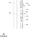
- the planning system 168 may generate a trajectory 810 for the vehicle 100 to follow in order to reverse in the pullover location (here parking spot 432) to make a gap between vehicle 100 and vehicle 520.
- the computing devices 110 must determine when the vehicle 100 should reverse along trajectory 810 before or after the passenger has entered the vehicle 100.
- the computing devices 110 may determine context for the pull over with respect to the passenger for the vehicle. For instance, if the context indicates that the actual passenger or a potential passenger (i.e. a pedestrian who may be the passenger) is nearby, the computing devices 110 should wait for the passenger to enter the vehicle 100 (and also close the door and/or buckle a seatbelt or other restraint device) before maneuvering the vehicle in reverse. If the context indicates that the actual passenger or a potential passenger is not nearby the vehicle, the computing devices 110 may maneuver the vehicle 100 in reverse before the passenger enters the vehicle. This may include reversing away from an object, such as vehicle 520, in front of the vehicle 100.
- an object such as vehicle 520
- the computing devices 110 may still determine that reversing before the passenger enters the vehicle, is in fact prudent in order to prevent the vehicle 100 from being "boxed in" by one or more other vehicles. This may be the case, for instance because another vehicle may be approaching the vehicle 100 from behind and appears to be pulling behind the vehicle 100 or because another vehicle behind the vehicle 100 is pulling out of a pullover location behind the vehicle 100 (such as, for example, vehicle 530 in parking spot 430). This may also be the case in high traffic areas where historically vehicles are attempting to locate and pull into parking spots and other pullover locations at the same or similar times (i.e.
- the computing devices 110 may have access to historical information about the volume of traffic in certain areas and/or the number of vehicles that were parked in a pullover location in the past. In those cases, it may be prudent to reverse in order to preserve space for the vehicle 100 to be able to pull out.
- the computing devices 110 may estimate a time to complete a maneuver, such as pulling into a pullover location, reversing and/or pulling the vehicle forward. For example, the estimated time to pull into a pullover location and reverse exceeds an estimate of how much time before the passenger is likely to arrive at the vehicle 100 (discussed further below), the computing devices 110 may determine that the vehicle should abandon the maneuver altogether (e.g. double park or simply stop and wait). As another example, if the vehicle is already located within the pullover location and the estimated time to pull forward and then reverse exceeds an estimate of how much time before the passenger is likely to arrive at the vehicle 110, the computing devices 110 may control the vehicle to pull into the pullover location forward (without reversing), wait for the passenger to board the vehicle, and thereafter reverse.
- the computing devices 110 may estimate a time to complete a maneuver, such as pulling into a pullover location, reversing and/or pulling the vehicle forward. For example, the estimated time to pull into a pullover location and reverse exceeds an estimate of how much time before the passenger
- the computing devices 110 may determine to maneuver the vehicle 110 forward in the pullover location and wait for the passenger to board, and thereafter reverse.
- This estimate of how soon another vehicle is likely to arrive at the vehicle 110 may be based on historical data for the pullover location or area around the pullover location and/or observations of the number of vehicles pulling into nearby pullover locations, the current volume of traffic, time of day, day of the week, day of the year, etc.
- the computing devices 110 may actually pull the vehicle forward, rather than reversing despite the context indicating that the passenger is likely to be nearby, the computing devices may actually pull the vehicle forward in order to preserve space. For example, if certain signals are observed by the perception system such as a person entering the other vehicle, a turn signal being activated, exhaust appearing from the other vehicle, etc., the computing devices 110 may determine that the other vehicle is likely to be pulling out of a pullover location. Again, in such cases, the computing devices may actually pull the vehicle forward in order to preserve space.
- the computing devices 110 may communicate a message to the passenger via external tertiary communications systems (for example audio via a speaker, displaying on a display screen, etc.) or by sending a message (for example, via network 460), to the passengers client computing device, to indicate to the passenger that the passenger should wait for the vehicle to complete a reversing maneuver before attempting entering the vehicle.
- external tertiary communications systems for example audio via a speaker, displaying on a display screen, etc.
- a message for example, via network 460
- determining the context may include determining how much time before the passenger is likely to arrive at the vehicle 100. This determination may be made for instance, based on location information for a client computing device associated with the passenger. For example, the computing devices 110may periodically receive location information (such as GPS coordinates) generated by the passenger's client computing device (e.g. mobile phone). This location information may be received from a server computing device of a dispatching system for the vehicle 100 and/or directly from the client computing device. The computing devices 110may determine if this location information indicates that the passenger is likely to reach the vehicle 100's current location within a predetermined threshold period of time assuming a normal walking speed, such as 2 meters per second.
- location information such as GPS coordinates
- This location information may be received from a server computing device of a dispatching system for the vehicle 100 and/or directly from the client computing device.
- the computing devices 110 may determine if this location information indicates that the passenger is likely to reach the vehicle 100's current location within a predetermined threshold period of time assuming a normal walking speed, such
- the computing devices 110 should wait for the passenger to enter the vehicle 100 before maneuvering the vehicle in reverse. If not, the computing devices 110 may maneuver the vehicle 100 in reverse before the passenger enters the vehicle.
- the computing devices 110 may determine how much time before the passenger is likely to arrive at the vehicle 100 based on historical data for the passenger and/or other passengers.
- the historical data may include aggregated statistics about how long on average this passenger and/or other passengers take to reach a vehicle once a vehicle is stopped to pick up such passengers at the identified pullover locations, nearby pullover locations (e.g. no more than 50 meters in walking distance or straight line distance away or more or less), or other similar locations (such as similarly sized or situated parking lots or similar types of stores) .
- the historical data may also be "sliced" that is segmented for different predetermined times of day and/or days of the week. This historical data may be embedded in map information and associated with geographic regions including a plurality of pullover locations and/or with specific pullover locations. From this historical data, the computing devices 110 may determine an expected amount of time for the passenger to reach the vehicle 100.
- the computing devices 110 may then determine if this expected amount of time indicates that the passenger is likely to reach the vehicle 100's current location within a predetermined threshold period of time assuming a normal walking speed (which may be 2 meters per second or more or less). If so, this may indicate that the actual passenger is nearby the vehicle 100, and in such circumstances, the computing devices 110 should wait for the passenger to enter the vehicle before maneuvering the vehicle in reverse. If not, the computing devices 110 may maneuver the vehicle 100 in reverse before the passenger enters the vehicle.
- a normal walking speed which may be 2 meters per second or more or less
- determining the context may include determining whether there are any pedestrians nearby of the vehicle 100.
- the computing devices 110 may use sensor data from the vehicle 100's perception system to identify or detect pedestrians within a predetermined threshold distance of the vehicle 100, for example within 100 meters or more or less. This may indicate that a potential passenger is nearby the vehicle 100 and possibly ready to approach the vehicle, and in such circumstances, the computing devices 110 should wait for the passenger to enter the vehicle before maneuvering the vehicle in reverse. If not, the computing devices 110 may maneuver the vehicle 100 in reverse before the passenger enters the vehicle.
- determining the context may include determining whether there are any pedestrians who are actively making progress towards the vehicle 100.
- the computing devices 110 may predict a future trajectory for the object and if it overlaps with the location of the vehicle 100, this may indicate that the pedestrian is actively making progress towards the vehicle. Again, this may indicate that a potential passenger is nearby the vehicle 100 and possibly approaching the vehicle, and in such circumstances, the computing devices 110 should wait for the passenger to enter the vehicle before maneuvering the vehicle in reverse. If not, the computing devices 110 may maneuver the vehicle 100 in reverse before the passenger enters the vehicle.
- determining the context may include determining whether the computing devices 110 have established a communications link with and/or authenticated a client computing device associated with the passenger (whether or not a pedestrian is detected nearby the vehicle 100). For example, once within a certain distance or time, such as 50 meters or more or less or 25 seconds or more or less, of a pickup location for the passenger, the computing devices 110 may attempt to establish a Bluetooth (R) communication link between the passenger's client computing device (e.g. mobile phone) and the computing devices 110. Once this has occurred, because Bluetooth (R) connections are generally made over fairly short distances, this may indicate that the actual passenger is nearby the vehicle 100, and in such circumstances, the computing devices 110 should wait for the passenger to enter the vehicle 100 before maneuvering the vehicle in reverse. If not, the computing devices 110 may maneuver the vehicle 100 in reverse before the passenger enters the vehicle.
- a Bluetooth (R) communication link between the passenger's client computing device (e.g. mobile phone) and the computing devices 110.
- determining the context may include determining whether location information for a client computing device of the passenger indicates that the passenger is nearby the vehicle 100.
- the computing devices 110 may periodically receive location information (such as GPS coordinates) generated by the passenger's client computing device (e.g. mobile phone). This location information may be received from a server computing device of a dispatching system for the vehicle 100 and/or directly from the client computing device.
- the computing devices 110 may determine if this location information indicates that the passenger is within a predetermined threshold distance, such as 100 meters or more or less, of the current location of the vehicle 100. If so, this may indicate that the actual passenger is nearby the vehicle 100, and in such circumstances, the computing devices 110 should wait for the passenger to enter the vehicle before maneuvering the vehicle in reverse. If not, the computing devices 110 may maneuver the vehicle 100 in reverse before the passenger enters the vehicle.
- the vehicle is maneuvered in the autonomous driving mode in reverse based on the determination of whether to maneuver the vehicle in reverse in the pullover location before or after the passenger enters the vehicle. For instance, based on the examples above, if any of the context indicates that the vehicle 100 should wait for the passenger to enter the vehicle 100, then the computing devices 110 may wait for a passenger to enter a vehicle, for instance in the location depicted in FIGURE 7 , before following trajectory 810 in order to reverse. Again, the vehicle 100 may be maneuvered in the autonomous driving mode towards vehicle 520, and the distance between vehicle 100 and vehicle 520, here D2 in FIGURE 9 may be on the order of a few inches or more or less.
- the computing devices 110 may then wait for the passenger to enter the vehicle. This may be confirmed, for instance by the door of the vehicle being opened and closed and/or a passenger initiating a ride, for example, by pressing a button within the vehicle or by speaking a command for the ride to start which may also cause the computing devices 110 to automatically close the doors of the vehicle.
- the planning system 168 may also generate trajectory 910 in order to enable the vehicle 100 to pull out of the pullover location (here parking spot 432).
- the computing devices 110 may also control the vehicle in the autonomous driving mode in order to follow trajectory 910.
- the computing devices 110 may control the vehicle to follow trajectory 810 as depicted in FIGURE 9 before waiting for the passenger to enter the vehicle.
- the vehicle 100 may be maneuvered in the autonomous driving mode towards vehicle 520, and the distance between vehicle 100 and vehicle 520, here D2 in FIGURE 9 may be on the order of a few inches or more or less.
- the planning system 168 may generate trajectory 910 in order to enable the vehicle 100 to pull out of the pullover location (here parking spot 432).
- the computing devices 110 may also control the vehicle in the autonomous driving mode in order to follow trajectory 910.
- the features described herein may enable an autonomous vehicle to implement specific parking behaviors. As noted above, these parking behaviors may improve the ability for the computing devices of a vehicle having an autonomous driving mode to find available pullover locations while doing so safely and avoiding parallel parking maneuvers. In other words, because the vehicle is able to find smaller parking locations (for instance, a 5.1-5.2 meter long van may be able to pull over in an 8 to 10 meter pullover location as opposed to a 15 or more meter pullover location), the vehicle may be more likely to find a pullover location to wait for a passenger and less likely to have to loop around one or more times before doing so.
- these parking behaviors may improve the ability for the computing devices of a vehicle having an autonomous driving mode to find available pullover locations while doing so safely and avoiding parallel parking maneuvers.
- the vehicle may be more likely to find a pullover location to wait for a passenger and less likely to have to loop around one or more times before doing so.
- timing of when a vehicle reverses in a pullover location is dependent upon the context for the pull over with respect to a potential or actual passenger for the vehicle, this may avoid situations in which the vehicle stops and an unknowing passenger attempts to enter the vehicle just before or while the vehicle is reversing, which again can be dangerous for the passenger.
Landscapes
- Engineering & Computer Science (AREA)
- Transportation (AREA)
- Mechanical Engineering (AREA)
- Automation & Control Theory (AREA)
- Chemical & Material Sciences (AREA)
- Combustion & Propulsion (AREA)
- Human Computer Interaction (AREA)
- Physics & Mathematics (AREA)
- General Physics & Mathematics (AREA)
- Radar, Positioning & Navigation (AREA)
- Remote Sensing (AREA)
- Aviation & Aerospace Engineering (AREA)
- Business, Economics & Management (AREA)
- Health & Medical Sciences (AREA)
- Artificial Intelligence (AREA)
- Evolutionary Computation (AREA)
- Game Theory and Decision Science (AREA)
- Medical Informatics (AREA)
- Traffic Control Systems (AREA)
- Control Of Driving Devices And Active Controlling Of Vehicle (AREA)
Claims (14)
- Verfahren für das Manövrieren eines Fahrzeugs (100) mit einem autonomen Fahrmodus, das Verfahren umfassend:Identifizieren (1010), durch einen oder mehrere Prozessoren, eines Haltestandorts (432), an dem das Fahrzeug anhält und auf einen Fahrgast wartet;Manövrieren (1020), durch den einen oder die mehreren Prozessoren, des Fahrzeugs in dem autonomen Fahrmodus, um am Straßenrand anzuhalten, indem es in dem Haltestandort vorfährt;Ermitteln (1030), durch den einen oder die mehreren Prozessoren, ob das Fahrzeug vor oder nach dem Einsteigen des Fahrgasts in das Fahrzeug in dem Haltestandort zurück zu manövrieren ist, basierend auf dem Kontext für das Anhalten am Straßenrand in Bezug auf den Fahrgast; undZurückmanövrieren (1040), durch den einen oder die mehreren Prozessoren, des Fahrzeugs in dem autonomen Fahrmodus basierend auf dem Ermitteln, ob das Fahrzeug vor oder nach dem Einsteigen des Fahrgasts in das Fahrzeug in dem Haltestandort zurück zu manövrieren ist, wobei die Ermittlung, ob das Fahrzeug vor oder nach dem Einsteigen des Fahrgasts in das Fahrzeug in dem Haltestandort zurückmanövriert wird, auf Folgendem basiert:Ermitteln des Kontexts durch Ermitteln einer erwarteten Zeitdauer, bis der Fahrgast das Fahrzeug erreicht, sobald das Fahrzeug bereit ist, in dem Haltestandort zurückmanövriert zu werden; undVergleichen der erwarteten Zeitdauer mit einem Schwellenwert.
- Verfahren nach Anspruch 1, ferner umfassend, wenn das Fahrzeug manövriert wird, um am Straßenrand anzuhalten, indem es in dem Haltestandort vorfährt, Einstellen eines minimalen Abstands für das Fahrzeug in Bezug auf andere Objekte, um das Fahrzeug in den eingestellten minimalen Abstand zu einem anderen Objekt vor dem Fahrzeug zu manövrieren.
- Verfahren nach Anspruch 1 oder Anspruch 2, ferner umfassend das Ermitteln des Kontexts durch das Ermitteln, dass ein Fußgänger sich innerhalb eines vorbestimmten Schwellenabstands des Haltestandorts befindet, und wobei das Zurückmanövrieren des Fahrzeugs das Zurückmanövrieren des Fahrzeugs nach dem Einsteigen des Fahrgasts in das Fahrzeug beinhaltet.
- Verfahren nach einem der Ansprüche 1 bis 3, ferner umfassend das Ermitteln des Kontexts durch das Ermitteln, dass ein Fußgänger sich nicht innerhalb eines vorbestimmten Schwellenabstands des Haltestandorts befindet, und wobei das Zurückmanövrieren des Fahrzeugs das Zurückmanövrieren des Fahrzeugs, vor dem Einsteigen des Fahrgasts in das Fahrzeug beinhaltet.
- Verfahren nach einem der Ansprüche 1 bis 4, wobei das Zurückmanövrieren des Fahrzeugs Folgendes beinhaltet:Zurückmanövrieren des Fahrzeugs vor dem Einsteigen des Fahrgasts in das Fahrzeug, wenn der Vergleich anzeigt, dass die erwartete Zeitdauer größer als der Schwellenwert ist; oderZurückmanövrieren des Fahrzeugs nach dem Einsteigen des Fahrgasts in das Fahrzeug, wenn der Vergleich anzeigt, dass die erwartete Zeitdauer kleiner als der Schwellenwert ist.
- Verfahren nach einem der Ansprüche 1 bis 5, wobei das Ermitteln der erwarteten Zeitdauer auf einer Standortinformation für ein mit dem Fahrgast assoziierten Client-Computergerät basiert.
- Verfahren nach Anspruch 6, wobei das Ermitteln der erwarteten Zeitdauer ferner auf einer vorbestimmten Gehgeschwindigkeit für Fußgänger basiert.
- Verfahren nach einem der Ansprüche 1 bis 7, wobei das Ermitteln der erwarteten Zeitdauer auf Folgendem basiert:historischen Daten, die angeben, wie lange der Fahrgast benötigt hat, um in der Vergangenheit ein oder mehrere Fahrzeuge für ein Abholen zu erreichen; und/oderhistorischen Daten, die eine erwartete Zeitdauer angeben, in der Fahrgäste ein oder mehrere Fahrzeuge für ein Abholen erreichen; und/oderhistorischen Daten, die eine erwartete Zeitdauer angeben, in der Fahrgäste ein oder mehrere Fahrzeuge für ein Abholen zu einer vorbestimmten Tageszeit erreichen; und/oderhistorischen Daten, die eine erwartete Zeitdauer angeben, in der Fahrgäste ein oder mehrere Fahrzeuge für ein Abholen an einem vorbestimmten Wochentag erreichen; und/oderhistorischen Daten, die eine erwartete Zeitdauer angeben, in der Fahrgäste ein oder mehrere Fahrzeuge für ein Abholen an dem Haltestandort erreichen; und/oderhistorischen Daten, die eine erwartete Zeitdauer angeben, in der Fahrgäste ein oder mehrere Fahrzeuge für ein Abholen in einer geografischen Region, einschließlich des Haltestandorts und einer oder mehrerer zusätzlicher Haltestandorte erreichen.
- Verfahren nach einem der Ansprüche 1 bis 8, ferner umfassend:Ermitteln des Kontexts durch Ermitteln, dass ein Fußgänger, der sich in Richtung des Fahrzeugs bewegt, sich innerhalb eines vorbestimmten Abstands des Haltestandorts befindet, und wobei das Zurückmanövrieren des Fahrzeugs das Zurückmanövrieren des Fahrzeugs nach dem Einsteigen des Fahrgasts beinhaltet; oderErmitteln des Kontexts durch Ermitteln, dass ein Fußgänger, der sich in Richtung des Fahrzeugs bewegt, sich nicht innerhalb eines vorbestimmten Abstands des Haltestandorts befindet, und wobei das Zurückmanövrieren des Fahrzeugs das Zurückmanövrieren des Fahrzeugs vor dem Einsteigen des Fahrgasts beinhaltet.
- Verfahren nach einem der Ansprüche 1 bis 9, ferner umfassend:Ermitteln des Kontexts durch Ermitteln, dass eine Kommunikationsverbindung zwischen einem oder mehreren Computergeräten des Fahrzeugs und einem mit dem Fahrgast assoziierten Client-Computergerät hergestellt wurde, und wobei das Zurückmanövrieren des Fahrzeugs das Zurückmanövrieren des Fahrzeugs nach dem Einsteigen des Fahrgasts beinhaltet; oderErmitteln des Kontexts durch Ermitteln, dass keine Kommunikationsverbindung zwischen einem oder mehreren Computergeräten des Fahrzeugs und einem mit dem Fahrgast assoziierten Client-Computergerät hergestellt wurde, und wobei das Zurückmanövrieren des Fahrzeugs das Zurückmanövrieren des Fahrzeugs vor dem Einsteigen des Fahrgasts beinhaltet.
- Verfahren nach einem der Ansprüche 1 bis 10, ferner umfassend:Ermitteln des Kontexts durch Ermitteln, dass die Standortinformationen für ein mit dem Fahrgast assoziierten Client-Computergerät innerhalb eines vorbestimmten Schwellenabstands des Fahrzeugs liegen, und wobei das Zurückmanövrieren des Fahrzeugs das Zurückmanövrieren des Fahrzeugs nach dem Einsteigen des Fahrgasts beinhaltet; oderErmitteln des Kontexts durch Ermitteln, dass die Standortinformationen für ein mit dem Fahrgast assoziierten Client-Computergerät nicht innerhalb eines vorbestimmten Schwellenwertabstands des Fahrzeugs liegen, und wobei das Zurückmanövrieren des Fahrzeugs das Zurückmanövrieren des Fahrzeugs vor dem Einsteigen des Fahrgasts beinhaltet.
- Verfahren nach einem der Ansprüche 1 bis 11, wobei das Zurückmanövrieren des Fahrzeugs das Zurückmanövrieren des Fahrzeugs vor dem Einsteigen des Fahrgasts in das Fahrzeug beinhaltet, und das Verfahren ferner das Bereitstellen einer Benachrichtigung umfasst, um dem Fahrgast anzuzeigen, dass der Fahrgast warten sollte, bis das Fahrzeug ein Rückfahrmanöver beendet hat, bevor er versucht, in das Fahrzeug einzusteigen.
- Fahrzeug (100) mit einem autonomen Fahrmodus, wobei das Fahrzeug einen oder mehrere Prozessoren umfasst, die zum Durchführen des Verfahrens nach einem der vorhergehenden Ansprüche konfiguriert sind.
- Computergerätelesbares Medium, umfassend Anweisungen, die, bei Ausführung durch einen oder mehrere Prozessoren (120), den einen oder die mehreren Prozessoren veranlassen, das Verfahren nach einem der Ansprüche 1 bis 12 durchzuführen.
Applications Claiming Priority (2)
| Application Number | Priority Date | Filing Date | Title |
|---|---|---|---|
| US16/536,560 US11048256B2 (en) | 2019-08-09 | 2019-08-09 | Parking behaviors for autonomous vehicles |
| PCT/US2020/045406 WO2021030189A1 (en) | 2019-08-09 | 2020-08-07 | Parking behaviors for autonomous vehicles |
Publications (3)
| Publication Number | Publication Date |
|---|---|
| EP3990331A1 EP3990331A1 (de) | 2022-05-04 |
| EP3990331A4 EP3990331A4 (de) | 2023-07-05 |
| EP3990331B1 true EP3990331B1 (de) | 2024-12-11 |
Family
ID=74498853
Family Applications (1)
| Application Number | Title | Priority Date | Filing Date |
|---|---|---|---|
| EP20851761.5A Active EP3990331B1 (de) | 2019-08-09 | 2020-08-07 | Parkverhalten für autonome fahrzeuge |
Country Status (5)
| Country | Link |
|---|---|
| US (2) | US11048256B2 (de) |
| EP (1) | EP3990331B1 (de) |
| JP (1) | JP7270834B2 (de) |
| CN (1) | CN114555448B (de) |
| WO (1) | WO2021030189A1 (de) |
Families Citing this family (14)
| Publication number | Priority date | Publication date | Assignee | Title |
|---|---|---|---|---|
| JP6967417B2 (ja) * | 2017-10-03 | 2021-11-17 | 株式会社 ミックウェア | 経路生成装置、及びプログラム |
| US10520941B2 (en) * | 2017-12-15 | 2019-12-31 | Waymo Llc | Suggesting alternative pickup and drop off locations for autonomous vehicles |
| JP2022028092A (ja) * | 2018-12-20 | 2022-02-15 | ソニーグループ株式会社 | 車両制御装置、車両制御方法、プログラム、及び、車両 |
| US11048256B2 (en) * | 2019-08-09 | 2021-06-29 | Waymo Llc | Parking behaviors for autonomous vehicles |
| US20220222600A1 (en) * | 2019-09-30 | 2022-07-14 | Gm Cruise Holdings Llc | User authentication and personalization without user credentials |
| EP3865376B1 (de) * | 2020-02-13 | 2024-10-09 | Volvo Car Corporation | Automatisiertes einparkassistenzsystem zum einparken eines fahrzeugs in einer parklücke |
| US11794779B2 (en) | 2021-03-19 | 2023-10-24 | Waymo Llc | Pullover maneuvers for autonomous vehicles |
| US11859989B2 (en) | 2021-08-24 | 2024-01-02 | Waymo Llc | Speed reasoning in the presence of uncertainty when pulling over |
| US20230060500A1 (en) * | 2021-08-31 | 2023-03-02 | Zoox, Inc. | Remote assistance for vehicles |
| USD1014398S1 (en) | 2021-12-23 | 2024-02-13 | Waymo Llc | Vehicle |
| USD1018337S1 (en) | 2021-12-23 | 2024-03-19 | Waymo Llc | Sensor assembly |
| US12409855B2 (en) | 2022-01-19 | 2025-09-09 | Waymo Llc | Managing maneuvers for autonomous vehicles in certain situations |
| CN114863717B (zh) * | 2022-06-14 | 2023-06-30 | 小米汽车科技有限公司 | 车位推荐方法、装置、存储介质及车辆 |
| JP7670017B2 (ja) * | 2022-10-19 | 2025-04-30 | トヨタ自動車株式会社 | 駐車支援装置 |
Family Cites Families (33)
| Publication number | Priority date | Publication date | Assignee | Title |
|---|---|---|---|---|
| DE10339645A1 (de) * | 2003-08-28 | 2005-04-14 | Robert Bosch Gmbh | Verfahren und Vorrichtung zur Bestimmung von Größe und Position einer Parklücke |
| JP4086060B2 (ja) * | 2005-08-17 | 2008-05-14 | トヨタ自動車株式会社 | 点列の近似方法および点列の近似装置 |
| ATE548245T1 (de) * | 2008-04-03 | 2012-03-15 | Valeo Schalter & Sensoren Gmbh | Verfahren und vorrichtung zur unterstützung eines fahres eines fahrzeugs beim ausparken aus einer parklücke |
| CN102598080B (zh) | 2010-04-12 | 2014-07-23 | 丰田自动车株式会社 | 车辆远程操作系统以及车载机器 |
| US9008890B1 (en) | 2013-03-15 | 2015-04-14 | Google Inc. | Augmented trajectories for autonomous vehicles |
| US9523984B1 (en) | 2013-07-12 | 2016-12-20 | Google Inc. | Methods and systems for determining instructions for pulling over an autonomous vehicle |
| US9720410B2 (en) | 2014-03-03 | 2017-08-01 | Waymo Llc | Remote assistance for autonomous vehicles in predetermined situations |
| US9436182B2 (en) * | 2014-05-23 | 2016-09-06 | Google Inc. | Autonomous vehicles |
| DE102014011811B4 (de) * | 2014-08-09 | 2018-08-09 | Audi Ag | Informieren eines Verkehrsteilnehmers über eine autopilotgesteuerte Fahrt |
| US10311731B1 (en) * | 2014-09-16 | 2019-06-04 | Knightscope, Inc. | Autonomous parking monitor |
| JP6553470B2 (ja) * | 2015-09-29 | 2019-07-31 | 株式会社Subaru | 危険度算出装置 |
| US10325502B2 (en) * | 2016-02-10 | 2019-06-18 | Ford Global Technologies, Llc | Parallel parking assistant |
| JP6854095B2 (ja) * | 2016-07-01 | 2021-04-07 | フォルシアクラリオン・エレクトロニクス株式会社 | 駐車支援装置 |
| KR102003940B1 (ko) | 2016-11-11 | 2019-10-01 | 엘지전자 주식회사 | 자율 주행 차량 및 그 제어방법 |
| US10481609B2 (en) * | 2016-12-09 | 2019-11-19 | Ford Global Technologies, Llc | Parking-lot-navigation system and method |
| US10183665B2 (en) * | 2016-12-15 | 2019-01-22 | Unitronics Automated Solutions Ltd | System and method of automated parking system for autonomous vehicles |
| IL288191B2 (en) | 2016-12-23 | 2023-10-01 | Mobileye Vision Technologies Ltd | Navigational system with imposed liability constraints |
| US10214240B2 (en) * | 2017-04-20 | 2019-02-26 | GM Global Technology Operations LLC | Parking scoring for autonomous vehicles |
| US10440536B2 (en) * | 2017-05-19 | 2019-10-08 | Waymo Llc | Early boarding of passengers in autonomous vehicles |
| KR102001917B1 (ko) | 2017-05-29 | 2019-07-19 | 엘지전자 주식회사 | 차량용 주차 시스템 및 차량 |
| US11493348B2 (en) * | 2017-06-23 | 2022-11-08 | Direct Current Capital LLC | Methods for executing autonomous rideshare requests |
| US10627815B2 (en) * | 2017-08-22 | 2020-04-21 | Waymo Llc | Context aware stopping for autonomous vehicles |
| US20190066515A1 (en) * | 2017-08-22 | 2019-02-28 | Waymo Llc | Estimating time to pick up and drop off passengers for improved stopping analysis in autonomous vehicles |
| US11151482B2 (en) | 2017-08-31 | 2021-10-19 | Waymo Llc | Identifying unassigned passengers for autonomous vehicles |
| US10759433B2 (en) | 2017-10-16 | 2020-09-01 | Ford Global Technologies, Llc | Vehicle escape |
| US20190156678A1 (en) * | 2017-11-20 | 2019-05-23 | Tony Mitchell Cole | Systems and methods for coordinated passenger offloading of autonomous vehicles at large scale parking destinations |
| US10401863B2 (en) | 2017-11-22 | 2019-09-03 | GM Global Technology Operations LLC | Road corridor |
| JP6617987B2 (ja) | 2018-04-12 | 2019-12-11 | パナソニックIpマネジメント株式会社 | 配車システム、配車制御装置 |
| US10909866B2 (en) * | 2018-07-20 | 2021-02-02 | Cybernet Systems Corp. | Autonomous transportation system and methods |
| CN109455180B (zh) * | 2018-11-09 | 2020-10-16 | 百度在线网络技术(北京)有限公司 | 用于控制无人车的方法和装置 |
| DE102019000704A1 (de) * | 2019-01-31 | 2019-06-13 | Daimler Ag | Verfahren zum Betreiben elnes Kraftfahrzeugs |
| US11048256B2 (en) * | 2019-08-09 | 2021-06-29 | Waymo Llc | Parking behaviors for autonomous vehicles |
| US11880198B2 (en) | 2019-08-19 | 2024-01-23 | Toyota Motor North America, Inc. | Vehicle adaptive crawl control |
-
2019
- 2019-08-09 US US16/536,560 patent/US11048256B2/en active Active
-
2020
- 2020-08-07 WO PCT/US2020/045406 patent/WO2021030189A1/en not_active Ceased
- 2020-08-07 CN CN202080070483.6A patent/CN114555448B/zh active Active
- 2020-08-07 JP JP2022505436A patent/JP7270834B2/ja active Active
- 2020-08-07 EP EP20851761.5A patent/EP3990331B1/de active Active
-
2021
- 2021-05-26 US US17/330,973 patent/US11720102B2/en active Active
Also Published As
| Publication number | Publication date |
|---|---|
| US20210278844A1 (en) | 2021-09-09 |
| US20210041870A1 (en) | 2021-02-11 |
| CN114555448A (zh) | 2022-05-27 |
| US11048256B2 (en) | 2021-06-29 |
| US11720102B2 (en) | 2023-08-08 |
| WO2021030189A1 (en) | 2021-02-18 |
| JP7270834B2 (ja) | 2023-05-10 |
| EP3990331A4 (de) | 2023-07-05 |
| CN114555448B (zh) | 2023-05-16 |
| EP3990331A1 (de) | 2022-05-04 |
| JP2022543554A (ja) | 2022-10-13 |
Similar Documents
| Publication | Publication Date | Title |
|---|---|---|
| EP3990331B1 (de) | Parkverhalten für autonome fahrzeuge | |
| US11634134B2 (en) | Using discomfort for speed planning in responding to tailgating vehicles for autonomous vehicles | |
| US12565201B2 (en) | Early object detection for unprotected turns | |
| EP3795457B1 (de) | Vorbereitung von autonomen fahrzeugen für die kurvenfahrt | |
| EP3526093B1 (de) | Planung der stoppstandorte für autonome fahrzeuge | |
| US10627825B2 (en) | Using discomfort for speed planning in autonomous vehicles | |
| US11760354B2 (en) | Multi-way stop intersection precedence for autonomous vehicles | |
| US20250249936A1 (en) | Responding to emergency vehicles for autonomous vehicles | |
| US11794779B2 (en) | Pullover maneuvers for autonomous vehicles | |
| US12509117B2 (en) | Detecting and responding to malfunctioning traffic lights for autonomous vehicles | |
| US11327507B2 (en) | Exception handling for autonomous vehicles | |
| CA3131961C (en) | Signaling for turns for autonomous vehicles | |
| US11608066B1 (en) | Responding to input on a brake pedal of a brake by wire system for an autonomous vehicle | |
| US11460846B2 (en) | Unmarked crosswalks for autonomous vehicles |
Legal Events
| Date | Code | Title | Description |
|---|---|---|---|
| STAA | Information on the status of an ep patent application or granted ep patent |
Free format text: STATUS: THE INTERNATIONAL PUBLICATION HAS BEEN MADE |
|
| PUAI | Public reference made under article 153(3) epc to a published international application that has entered the european phase |
Free format text: ORIGINAL CODE: 0009012 |
|
| STAA | Information on the status of an ep patent application or granted ep patent |
Free format text: STATUS: REQUEST FOR EXAMINATION WAS MADE |
|
| 17P | Request for examination filed |
Effective date: 20220126 |
|
| AK | Designated contracting states |
Kind code of ref document: A1 Designated state(s): AL AT BE BG CH CY CZ DE DK EE ES FI FR GB GR HR HU IE IS IT LI LT LU LV MC MK MT NL NO PL PT RO RS SE SI SK SM TR |
|
| DAV | Request for validation of the european patent (deleted) | ||
| DAX | Request for extension of the european patent (deleted) | ||
| A4 | Supplementary search report drawn up and despatched |
Effective date: 20230606 |
|
| RIC1 | Information provided on ipc code assigned before grant |
Ipc: B60W 50/00 20060101ALI20230531BHEP Ipc: G05D 1/00 20060101ALI20230531BHEP Ipc: B60W 40/08 20120101ALI20230531BHEP Ipc: B60W 30/18 20120101ALI20230531BHEP Ipc: B60W 60/00 20200101AFI20230531BHEP |
|
| STAA | Information on the status of an ep patent application or granted ep patent |
Free format text: STATUS: EXAMINATION IS IN PROGRESS |
|
| 17Q | First examination report despatched |
Effective date: 20240325 |
|
| GRAP | Despatch of communication of intention to grant a patent |
Free format text: ORIGINAL CODE: EPIDOSNIGR1 |
|
| STAA | Information on the status of an ep patent application or granted ep patent |
Free format text: STATUS: GRANT OF PATENT IS INTENDED |
|
| INTG | Intention to grant announced |
Effective date: 20240920 |
|
| GRAS | Grant fee paid |
Free format text: ORIGINAL CODE: EPIDOSNIGR3 |
|
| GRAA | (expected) grant |
Free format text: ORIGINAL CODE: 0009210 |
|
| STAA | Information on the status of an ep patent application or granted ep patent |
Free format text: STATUS: THE PATENT HAS BEEN GRANTED |
|
| AK | Designated contracting states |
Kind code of ref document: B1 Designated state(s): AL AT BE BG CH CY CZ DE DK EE ES FI FR GB GR HR HU IE IS IT LI LT LU LV MC MK MT NL NO PL PT RO RS SE SI SK SM TR |
|
| P01 | Opt-out of the competence of the unified patent court (upc) registered |
Free format text: CASE NUMBER: APP_59806/2024 Effective date: 20241105 |
|
| REG | Reference to a national code |
Ref country code: GB Ref legal event code: FG4D |
|
| REG | Reference to a national code |
Ref country code: CH Ref legal event code: EP |
|
| REG | Reference to a national code |
Ref country code: DE Ref legal event code: R096 Ref document number: 602020043102 Country of ref document: DE |
|
| REG | Reference to a national code |
Ref country code: IE Ref legal event code: FG4D |
|
| REG | Reference to a national code |
Ref country code: LT Ref legal event code: MG9D |
|
| PG25 | Lapsed in a contracting state [announced via postgrant information from national office to epo] |
Ref country code: HR Free format text: LAPSE BECAUSE OF FAILURE TO SUBMIT A TRANSLATION OF THE DESCRIPTION OR TO PAY THE FEE WITHIN THE PRESCRIBED TIME-LIMIT Effective date: 20241211 |
|
| PG25 | Lapsed in a contracting state [announced via postgrant information from national office to epo] |
Ref country code: FI Free format text: LAPSE BECAUSE OF FAILURE TO SUBMIT A TRANSLATION OF THE DESCRIPTION OR TO PAY THE FEE WITHIN THE PRESCRIBED TIME-LIMIT Effective date: 20241211 |
|
| PG25 | Lapsed in a contracting state [announced via postgrant information from national office to epo] |
Ref country code: BG Free format text: LAPSE BECAUSE OF FAILURE TO SUBMIT A TRANSLATION OF THE DESCRIPTION OR TO PAY THE FEE WITHIN THE PRESCRIBED TIME-LIMIT Effective date: 20241211 |
|
| REG | Reference to a national code |
Ref country code: NL Ref legal event code: MP Effective date: 20241211 |
|
| PG25 | Lapsed in a contracting state [announced via postgrant information from national office to epo] |
Ref country code: ES Free format text: LAPSE BECAUSE OF FAILURE TO SUBMIT A TRANSLATION OF THE DESCRIPTION OR TO PAY THE FEE WITHIN THE PRESCRIBED TIME-LIMIT Effective date: 20241211 |
|
| PG25 | Lapsed in a contracting state [announced via postgrant information from national office to epo] |
Ref country code: NO Free format text: LAPSE BECAUSE OF FAILURE TO SUBMIT A TRANSLATION OF THE DESCRIPTION OR TO PAY THE FEE WITHIN THE PRESCRIBED TIME-LIMIT Effective date: 20250311 |
|
| PG25 | Lapsed in a contracting state [announced via postgrant information from national office to epo] |
Ref country code: GR Free format text: LAPSE BECAUSE OF FAILURE TO SUBMIT A TRANSLATION OF THE DESCRIPTION OR TO PAY THE FEE WITHIN THE PRESCRIBED TIME-LIMIT Effective date: 20250312 Ref country code: LV Free format text: LAPSE BECAUSE OF FAILURE TO SUBMIT A TRANSLATION OF THE DESCRIPTION OR TO PAY THE FEE WITHIN THE PRESCRIBED TIME-LIMIT Effective date: 20241211 |
|
| PG25 | Lapsed in a contracting state [announced via postgrant information from national office to epo] |
Ref country code: RS Free format text: LAPSE BECAUSE OF FAILURE TO SUBMIT A TRANSLATION OF THE DESCRIPTION OR TO PAY THE FEE WITHIN THE PRESCRIBED TIME-LIMIT Effective date: 20250311 |
|
| PG25 | Lapsed in a contracting state [announced via postgrant information from national office to epo] |
Ref country code: NL Free format text: LAPSE BECAUSE OF FAILURE TO SUBMIT A TRANSLATION OF THE DESCRIPTION OR TO PAY THE FEE WITHIN THE PRESCRIBED TIME-LIMIT Effective date: 20241211 |
|
| REG | Reference to a national code |
Ref country code: AT Ref legal event code: MK05 Ref document number: 1750187 Country of ref document: AT Kind code of ref document: T Effective date: 20241211 |
|
| PG25 | Lapsed in a contracting state [announced via postgrant information from national office to epo] |
Ref country code: SM Free format text: LAPSE BECAUSE OF FAILURE TO SUBMIT A TRANSLATION OF THE DESCRIPTION OR TO PAY THE FEE WITHIN THE PRESCRIBED TIME-LIMIT Effective date: 20241211 |
|
| PG25 | Lapsed in a contracting state [announced via postgrant information from national office to epo] |
Ref country code: PL Free format text: LAPSE BECAUSE OF FAILURE TO SUBMIT A TRANSLATION OF THE DESCRIPTION OR TO PAY THE FEE WITHIN THE PRESCRIBED TIME-LIMIT Effective date: 20241211 |
|
| PG25 | Lapsed in a contracting state [announced via postgrant information from national office to epo] |
Ref country code: IS Free format text: LAPSE BECAUSE OF FAILURE TO SUBMIT A TRANSLATION OF THE DESCRIPTION OR TO PAY THE FEE WITHIN THE PRESCRIBED TIME-LIMIT Effective date: 20250411 |
|
| PG25 | Lapsed in a contracting state [announced via postgrant information from national office to epo] |
Ref country code: PT Free format text: LAPSE BECAUSE OF FAILURE TO SUBMIT A TRANSLATION OF THE DESCRIPTION OR TO PAY THE FEE WITHIN THE PRESCRIBED TIME-LIMIT Effective date: 20250411 |
|
| PG25 | Lapsed in a contracting state [announced via postgrant information from national office to epo] |
Ref country code: EE Free format text: LAPSE BECAUSE OF FAILURE TO SUBMIT A TRANSLATION OF THE DESCRIPTION OR TO PAY THE FEE WITHIN THE PRESCRIBED TIME-LIMIT Effective date: 20241211 |
|
| PG25 | Lapsed in a contracting state [announced via postgrant information from national office to epo] |
Ref country code: AT Free format text: LAPSE BECAUSE OF FAILURE TO SUBMIT A TRANSLATION OF THE DESCRIPTION OR TO PAY THE FEE WITHIN THE PRESCRIBED TIME-LIMIT Effective date: 20241211 Ref country code: RO Free format text: LAPSE BECAUSE OF FAILURE TO SUBMIT A TRANSLATION OF THE DESCRIPTION OR TO PAY THE FEE WITHIN THE PRESCRIBED TIME-LIMIT Effective date: 20241211 |
|
| PG25 | Lapsed in a contracting state [announced via postgrant information from national office to epo] |
Ref country code: SK Free format text: LAPSE BECAUSE OF FAILURE TO SUBMIT A TRANSLATION OF THE DESCRIPTION OR TO PAY THE FEE WITHIN THE PRESCRIBED TIME-LIMIT Effective date: 20241211 |
|
| PG25 | Lapsed in a contracting state [announced via postgrant information from national office to epo] |
Ref country code: CZ Free format text: LAPSE BECAUSE OF FAILURE TO SUBMIT A TRANSLATION OF THE DESCRIPTION OR TO PAY THE FEE WITHIN THE PRESCRIBED TIME-LIMIT Effective date: 20241211 |
|
| PG25 | Lapsed in a contracting state [announced via postgrant information from national office to epo] |
Ref country code: IT Free format text: LAPSE BECAUSE OF FAILURE TO SUBMIT A TRANSLATION OF THE DESCRIPTION OR TO PAY THE FEE WITHIN THE PRESCRIBED TIME-LIMIT Effective date: 20241211 |
|
| PG25 | Lapsed in a contracting state [announced via postgrant information from national office to epo] |
Ref country code: SE Free format text: LAPSE BECAUSE OF FAILURE TO SUBMIT A TRANSLATION OF THE DESCRIPTION OR TO PAY THE FEE WITHIN THE PRESCRIBED TIME-LIMIT Effective date: 20241211 |
|
| REG | Reference to a national code |
Ref country code: DE Ref legal event code: R097 Ref document number: 602020043102 Country of ref document: DE |
|
| PG25 | Lapsed in a contracting state [announced via postgrant information from national office to epo] |
Ref country code: DK Free format text: LAPSE BECAUSE OF FAILURE TO SUBMIT A TRANSLATION OF THE DESCRIPTION OR TO PAY THE FEE WITHIN THE PRESCRIBED TIME-LIMIT Effective date: 20241211 |
|
| PGFP | Annual fee paid to national office [announced via postgrant information from national office to epo] |
Ref country code: DE Payment date: 20250827 Year of fee payment: 6 |
|
| PGFP | Annual fee paid to national office [announced via postgrant information from national office to epo] |
Ref country code: GB Payment date: 20250826 Year of fee payment: 6 |
|
| PLBE | No opposition filed within time limit |
Free format text: ORIGINAL CODE: 0009261 |
|
| STAA | Information on the status of an ep patent application or granted ep patent |
Free format text: STATUS: NO OPPOSITION FILED WITHIN TIME LIMIT |
|
| PGFP | Annual fee paid to national office [announced via postgrant information from national office to epo] |
Ref country code: FR Payment date: 20250825 Year of fee payment: 6 |
|
| REG | Reference to a national code |
Ref country code: CH Ref legal event code: L10 Free format text: ST27 STATUS EVENT CODE: U-0-0-L10-L00 (AS PROVIDED BY THE NATIONAL OFFICE) Effective date: 20251022 |
|
| 26N | No opposition filed |
Effective date: 20250912 |
|
| REG | Reference to a national code |
Ref country code: CH Ref legal event code: H13 Free format text: ST27 STATUS EVENT CODE: U-0-0-H10-H13 (AS PROVIDED BY THE NATIONAL OFFICE) Effective date: 20260324 |
|
| PG25 | Lapsed in a contracting state [announced via postgrant information from national office to epo] |
Ref country code: MC Free format text: LAPSE BECAUSE OF FAILURE TO SUBMIT A TRANSLATION OF THE DESCRIPTION OR TO PAY THE FEE WITHIN THE PRESCRIBED TIME-LIMIT Effective date: 20241211 |
|
| PG25 | Lapsed in a contracting state [announced via postgrant information from national office to epo] |
Ref country code: LU Free format text: LAPSE BECAUSE OF NON-PAYMENT OF DUE FEES Effective date: 20250807 |
|
| PG25 | Lapsed in a contracting state [announced via postgrant information from national office to epo] |
Ref country code: CH Free format text: LAPSE BECAUSE OF NON-PAYMENT OF DUE FEES Effective date: 20250831 |