EP3989786B1 - Sous-vide-gerät - Google Patents
Sous-vide-gerät Download PDFInfo
- Publication number
- EP3989786B1 EP3989786B1 EP20832680.1A EP20832680A EP3989786B1 EP 3989786 B1 EP3989786 B1 EP 3989786B1 EP 20832680 A EP20832680 A EP 20832680A EP 3989786 B1 EP3989786 B1 EP 3989786B1
- Authority
- EP
- European Patent Office
- Prior art keywords
- interior space
- cooking device
- power cord
- housing
- metallic conductors
- Prior art date
- Legal status (The legal status is an assumption and is not a legal conclusion. Google has not performed a legal analysis and makes no representation as to the accuracy of the status listed.)
- Active
Links
Images


Classifications
-
- A—HUMAN NECESSITIES
- A47—FURNITURE; DOMESTIC ARTICLES OR APPLIANCES; COFFEE MILLS; SPICE MILLS; SUCTION CLEANERS IN GENERAL
- A47J—KITCHEN EQUIPMENT; COFFEE MILLS; SPICE MILLS; APPARATUS FOR MAKING BEVERAGES
- A47J36/00—Parts, details or accessories of cooking-vessels
- A47J36/16—Inserts
- A47J36/165—Stirring devices operatively connected to cooking vessels when being removably inserted inside
-
- A—HUMAN NECESSITIES
- A47—FURNITURE; DOMESTIC ARTICLES OR APPLIANCES; COFFEE MILLS; SPICE MILLS; SUCTION CLEANERS IN GENERAL
- A47J—KITCHEN EQUIPMENT; COFFEE MILLS; SPICE MILLS; APPARATUS FOR MAKING BEVERAGES
- A47J27/00—Cooking-vessels
- A47J27/004—Cooking-vessels with integral electrical heating means
-
- A—HUMAN NECESSITIES
- A47—FURNITURE; DOMESTIC ARTICLES OR APPLIANCES; COFFEE MILLS; SPICE MILLS; SUCTION CLEANERS IN GENERAL
- A47J—KITCHEN EQUIPMENT; COFFEE MILLS; SPICE MILLS; APPARATUS FOR MAKING BEVERAGES
- A47J27/00—Cooking-vessels
- A47J27/10—Cooking-vessels with water-bath arrangements for domestic use
-
- A—HUMAN NECESSITIES
- A47—FURNITURE; DOMESTIC ARTICLES OR APPLIANCES; COFFEE MILLS; SPICE MILLS; SUCTION CLEANERS IN GENERAL
- A47J—KITCHEN EQUIPMENT; COFFEE MILLS; SPICE MILLS; APPARATUS FOR MAKING BEVERAGES
- A47J36/00—Parts, details or accessories of cooking-vessels
- A47J36/24—Warming devices
- A47J36/2405—Warming devices for warming food contained in vessels immersed in a water bath, e.g. chafers or steam tables
-
- H—ELECTRICITY
- H01—ELECTRIC ELEMENTS
- H01B—CABLES; CONDUCTORS; INSULATORS; SELECTION OF MATERIALS FOR THEIR CONDUCTIVE, INSULATING OR DIELECTRIC PROPERTIES
- H01B13/00—Apparatus or processes specially adapted for manufacturing conductors or cables
- H01B13/06—Insulating conductors or cables
- H01B13/14—Insulating conductors or cables by extrusion
-
- H—ELECTRICITY
- H01—ELECTRIC ELEMENTS
- H01B—CABLES; CONDUCTORS; INSULATORS; SELECTION OF MATERIALS FOR THEIR CONDUCTIVE, INSULATING OR DIELECTRIC PROPERTIES
- H01B17/00—Insulators or insulating bodies characterised by their form
- H01B17/36—Insulators having evacuated or gas-filled spaces
-
- H—ELECTRICITY
- H01—ELECTRIC ELEMENTS
- H01B—CABLES; CONDUCTORS; INSULATORS; SELECTION OF MATERIALS FOR THEIR CONDUCTIVE, INSULATING OR DIELECTRIC PROPERTIES
- H01B3/00—Insulators or insulating bodies characterised by the insulating materials; Selection of materials for their insulating or dielectric properties
- H01B3/18—Insulators or insulating bodies characterised by the insulating materials; Selection of materials for their insulating or dielectric properties mainly consisting of organic substances
- H01B3/30—Insulators or insulating bodies characterised by the insulating materials; Selection of materials for their insulating or dielectric properties mainly consisting of organic substances plastics; resins; waxes
- H01B3/44—Insulators or insulating bodies characterised by the insulating materials; Selection of materials for their insulating or dielectric properties mainly consisting of organic substances plastics; resins; waxes vinyl resins; acrylic resins
- H01B3/443—Insulators or insulating bodies characterised by the insulating materials; Selection of materials for their insulating or dielectric properties mainly consisting of organic substances plastics; resins; waxes vinyl resins; acrylic resins from vinylhalogenides or other halogenoethylenic compounds
- H01B3/445—Insulators or insulating bodies characterised by the insulating materials; Selection of materials for their insulating or dielectric properties mainly consisting of organic substances plastics; resins; waxes vinyl resins; acrylic resins from vinylhalogenides or other halogenoethylenic compounds from vinylfluorides or other fluoroethylenic compounds
-
- H—ELECTRICITY
- H01—ELECTRIC ELEMENTS
- H01B—CABLES; CONDUCTORS; INSULATORS; SELECTION OF MATERIALS FOR THEIR CONDUCTIVE, INSULATING OR DIELECTRIC PROPERTIES
- H01B7/00—Insulated conductors or cables characterised by their form
- H01B7/42—Insulated conductors or cables characterised by their form with arrangements for heat dissipation or conduction
- H01B7/421—Insulated conductors or cables characterised by their form with arrangements for heat dissipation or conduction for heat dissipation
-
- F—MECHANICAL ENGINEERING; LIGHTING; HEATING; WEAPONS; BLASTING
- F16—ENGINEERING ELEMENTS AND UNITS; GENERAL MEASURES FOR PRODUCING AND MAINTAINING EFFECTIVE FUNCTIONING OF MACHINES OR INSTALLATIONS; THERMAL INSULATION IN GENERAL
- F16K—VALVES; TAPS; COCKS; ACTUATING-FLOATS; DEVICES FOR VENTING OR AERATING
- F16K17/00—Safety valves; Equalising valves, e.g. pressure relief valves
- F16K17/02—Safety valves; Equalising valves, e.g. pressure relief valves opening on surplus pressure on one side; closing on insufficient pressure on one side
- F16K17/04—Safety valves; Equalising valves, e.g. pressure relief valves opening on surplus pressure on one side; closing on insufficient pressure on one side spring-loaded
-
- H—ELECTRICITY
- H01—ELECTRIC ELEMENTS
- H01B—CABLES; CONDUCTORS; INSULATORS; SELECTION OF MATERIALS FOR THEIR CONDUCTIVE, INSULATING OR DIELECTRIC PROPERTIES
- H01B1/00—Conductors or conductive bodies characterised by the conductive materials; Selection of materials as conductors
- H01B1/02—Conductors or conductive bodies characterised by the conductive materials; Selection of materials as conductors mainly consisting of metals or alloys
-
- H—ELECTRICITY
- H01—ELECTRIC ELEMENTS
- H01B—CABLES; CONDUCTORS; INSULATORS; SELECTION OF MATERIALS FOR THEIR CONDUCTIVE, INSULATING OR DIELECTRIC PROPERTIES
- H01B7/00—Insulated conductors or cables characterised by their form
- H01B7/02—Disposition of insulation
- H01B7/0233—Cables with a predominant gas dielectric
-
- H—ELECTRICITY
- H01—ELECTRIC ELEMENTS
- H01B—CABLES; CONDUCTORS; INSULATORS; SELECTION OF MATERIALS FOR THEIR CONDUCTIVE, INSULATING OR DIELECTRIC PROPERTIES
- H01B7/00—Insulated conductors or cables characterised by their form
- H01B7/02—Disposition of insulation
- H01B7/0275—Disposition of insulation comprising one or more extruded layers of insulation
-
- H—ELECTRICITY
- H01—ELECTRIC ELEMENTS
- H01B—CABLES; CONDUCTORS; INSULATORS; SELECTION OF MATERIALS FOR THEIR CONDUCTIVE, INSULATING OR DIELECTRIC PROPERTIES
- H01B7/00—Insulated conductors or cables characterised by their form
- H01B7/04—Flexible cables, conductors, or cords, e.g. trailing cables
- H01B7/041—Flexible cables, conductors, or cords, e.g. trailing cables attached to mobile objects, e.g. portable tools, elevators, mining equipment, hoisting cables
Definitions
- the present invention relates to low temperature cooking appliances, and more particularly, but not exclusively to sous vide appliances.
- Low temperature cooking appliances such as sous vide appliances
- the sous vide appliance is an electrically powered appliance that heats the liquid circulated through the appliance in order to cook the food product.
- the sous vide appliance has an elongate housing which can be partially submerged in the liquid. The liquid is then drawn up through an inlet and circulated around a heating element before being dispensed. Sensors and control circuitry ensure accurate and consistent temperature of the dispsensed liquid. Because a portion of the appliance is submersed in liquid, there is a sealed area within the housing for housing the circuitry and sensors to prevent damage from the liquid.
- US 2013/220143 A1 discloses an apparatus for cooking, which includes a housing, a display arranged on the housing and configured to display a cooking parameter selected through rotation of an annular knob, and a controller configured to control a heating element and a circulator according to a temperature of a fluid measured by a temperature sensor.
- Sous vide appliances are sold and used around the world and can become damaged during transit.
- the invention provides a cooking device according to claim 1 and a method of producing a cooking device according to claim 9. Further developments of the invention are defined in the dependent claims. Any embodiments and examples of the description not falling within the scope of the claims do not form part of the invention and are provided for illustrative purposes only.
- a cooking device including:
- the metallic conductors are each within a polymer coating and the at least one air path is between the metallic conductor and the respective polymer coating.
- the power cord is sealingly connected to the housing.
- the polymer coatings extruded about each of the metallic conductors has poor adhesion to the metallic conductors.
- the polymer coating includes polytetrafluoroethylene (Teflon TM ).
- the power cord further includes an outer polymer extruded to encase a length of all the metallic conductors and the respective polymer coatings.
- one end of the power cord has a plug compatible with the external power source.
- the outer polymer is a polyvinylchloride (PVC) and the plug is an over-molding of polytetrafluoroethylene (Teflon TM ).
- PVC polyvinylchloride
- Teflon TM polytetrafluoroethylene
- the metallic conductors are each stranded wires.
- the device further comprises guide structures to define a cord configuration within the housing.
- the guide structures include guide surfaces for maintaining the cord configuration such that any bend radius is not less than a minimum bend radius of at least 1.5 times the cord diameter.
- the device is a cooking device.
- the device above includes a duct communicating with the interior space to provide for the movement of air from within the interior space, and a movable valve member movable between a first position in which the valve member closes the duct, and a second position in which the valve member allows air to leave the interior space via the duct, wherein the valve member is biased toward the first position, and movable toward the second position when a predetermined pressure differential exists between air within the interior space and air outside the interior space.
- a polymer coating is extruded about each of the metallic conductors such that the at least one air path is formed between the metallic conductor and the respective polymer coating.
- the polymer coating is extruded about the metallic conductor at a temperature above ambient such that as the polymer coating cools, the at least one air path forms.
- the polymer coating includes polytetrafluoroethylene (Teflon TM ).
- the method may preferably further comprise extruding an outer polymer to encase a length of all the metallic conductors and the respective polymer coatings.
- the method may preferably further comprise over-molding a plug at one end of the encased length with a plug compatible with the external power source.
- the outer polymer is a polyvinylchloride (PVC) and the plug is polytetrafluoroethylene.
- PVC polyvinylchloride
- the metallic conductors are each stranded wires.
- the method may preferably further comprise, providing guide structures to define a path for the power cord within the housing.
- the path includes a curved configuration defined by guide surfaces on the guide structures such that a minimum curvature of the power cord in the curved configuration has a radius at least 1.5 times the cord diameter.
- the device is a sous vide appliance configured to heat and circulate a liquid to cook food.
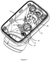
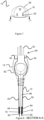
- the sous vide appliance 10 includes a housing 12 adapted to sealingly enclose an interior space 14.
- the housing 12 has longitudinally opposite ends 16, 18.
- At one end 16, is a user interface in the form of a screen 20.
- the screen 20 may be a single component or an assembly.
- the screen 20 has an internal surface 11 facing toward the interior space 14.
- Electric power is delivered to the sous vide appliance 10 via a power cord 13 connectable to a power source (not shown).
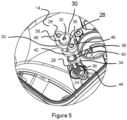
- the power cord 13 includes a first end having a connecting head, or plug, 15 connectable to the power source, and a second end 17 which extends into the interior space 14 of the sous vide appliance 10 to power the electronic components 22 via metallic conductors 60.
- the metallic connectors 60 include metal inserts 52 which form the terminals extending from the plug, and the wires 50 electrically connected to the metal inserts 52 and extending along the length of the cord 13 to the electronic components 22 within the interior space 14.
- the plug 15 includes an over-molding62 surrounding active, neutral and earth wires 50 which are connected to each respective metal insert 52.
- the over-molding 62 is a polymer, and more preferably, polytetrafluoroethylene, more commonly known as Teflon TM .
- Each of the wires 50 has a polymer coating 64 which is extruded about the wires at an elevated temperature.
- the polymer coating 64 is also Teflon TM which has a poor adhesion to the surface of the wires 50 and the metal insert 52. As the Teflon coatings and over-moldings cool to ambient temperature, gaps form between the wires 50 and their respective coatings 64 to provide an air path 19 within the power cord 13. If the wires 50 and stranded wires (i.e. individual metal strands twisted together to for the wire), the Teflon TM coatings 64 more readily detach and form the air paths 19.
- wires 50 and respective polymer coatings 64 are themselves encased in and outer polymer 66.
- the outer polymer 66 is extruded to encase the wires and polymer coatings from the plug 15, along the length of the cord 13 to the interior space 14 of the housing 12.
- the outer polymer 66 is a polyvinylchloride (PVC).
- the devices 10 experience a significant change of ambient air pressure, such as when freighted by air, the air paths 19 will vent the interior space 14 to avoid excessive stress or damage to the screen 20.
- the device 10 keeps the electronic components 22 sealed from any liquid being heated and circulated to cook food.
- the power cord 13 is fixed within the interior space 14 of the sous vide appliance 10.
- a clamp 54 seals the connection between the power cord 13 and the housing 12.
- Power is delivered to electronic components 22 disposed within the interior space 14 and connected to the screen 20 to operate the sous vide appliance 10. If the power cord 13 is kinked or bent to tightly within the housing 12, there is a chance the air paths 19 will close and the interior space 14 will not equalize to ambient pressure.
- guide structures 68 are provided in the housing 12 to hold the power cord 13 in a suitable configuration.
- the guide structures 68 have guide surfaces 70 to maintain a minimum cord curvature (i.e.
- the guide structures 68 can conveniently (but not necessarily) hold the power cord 13 in a desired bend radius using a guide surface 70 with the same curvature.
- the guide surfaces need not be curved but still determine the curvature of the cord given a known flexibility of the cord in its longitudinal direction.
- a pressure release valve may be used to regulate air pressure in the interior space 14 as a failsafe, bearing mind this entails higher production costs.
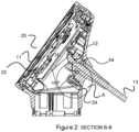
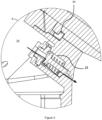
- a hollow cylinder 24 provides a duct extending from the interior space 14 to outside the interior space and allows air flow from the interior space 14 to assist with equalisation or regulation of pressure at different atmospheric pressure levels.
- the hollow cylinder 24 is positioned on a wall of the housing 12 opposite the screen 20. The longitudinal extent of the hollow cylinder 24 is generally transverse to the screen 20.
- a cap portion 26 is secured to the hollow cylinder 24 using threaded fasteners (not shown). The threaded fasteners pass though apertures 28 in the cap portion 26 and the hollow cylinder 24 to secure them together. As discussed below, a seal 42 is secured between the cap portion 26 and the valve member 34.
- the cap portion 26 includes a top protrusion 48 to assist in locating the seal 42.
- the cap portion 26 also includes opposing flat side portions 30 to accommodate adjacent components. It will be understood that other shapes for the cap portion 26 may be appropriate.
- the cap portion 26 further includes an aperture 32 to allow air pressure to press against the movable valve member 34 (described below).
- a movable valve member 34 is disposed within the hollow cylinder 24.
- the valve member 34 includes a stem portion 36 and a top portion 38.
- the top portion 38 has a generally circular cross section transverse to the stem portion 36 and a lip 40 around the perimeter to aid in locating the seal 42.
- the valve member 34 is movable between a first position in which the valve member closes 34 the duct 24 and a second position in which the valve member 34 allows air to leave the interior space 14 via the duct 24 (see arrow in Figure 3 ). This prevents any fluid ingress into the sous vide appliance 10 while ensuring the pressure difference between the interior space 14 and outside the interior space, is less than a pre-set threshold.
- a helical spring 44 located within the hollow cylinder 24, is positioned in engagement with the top portion 38 of the valve member 34 so as to urge the valve member 34 toward the first, or closed, position.
- the pressure differential for opening the valve member 34 can be changed by changing the stiffness of the spring 44.
- the seal 42 sealingly connects the valve member 34 with the hollow cylinder 24. As described above, lip 40 around the perimeter of the top portion 38 of the valve member 34 assists in locating the seal 42 promoting better contact between the valve member 34 and the seal 42 in the closed position.
- the seal 42 may be made of rubber or the like, and includes an aperture 46 to allow for air pressure to press against the top portion 38 of the valve member 34.
- valve member 34 may be designed to operate at different pressure differentials between inside the sous vide appliance 10 and outside the appliance. This can be controlled (in part) by modifying the stiffness of the spring 44.
- the stiffness of the spring 44 is set to a threshold pressure difference between the appliance and atmosphere is 50 kPa, then the following will occur:
- the valve member 34 acts as a one-way valve to outside the sous vide appliance 10.
- air pressure inside the appliance 10 may be far lower than atmospheric pressure at sea level, and this is not a problem because the appliance 10 can operate at 80 kPa (as shown above).
- the appliance 10 will build more internal air pressure during operations from the heat it is creating.
Landscapes
- Engineering & Computer Science (AREA)
- Food Science & Technology (AREA)
- Physics & Mathematics (AREA)
- Spectroscopy & Molecular Physics (AREA)
- Manufacturing & Machinery (AREA)
- Cookers (AREA)
Claims (15)
- Ein Kochgerät, das folgende Merkmale umfasst:ein Gehäuse, das einen Innenraum auf dichte Weise umschließt, wobei das Gehäuse einen Bildschirm mit einer Innenoberfläche, die einem Luftdruck in dem Innenraum ausgesetzt ist;elektronische Komponenten, die mit dem Bildschirm verbunden sind, um das Kochgerät zu betreiben, wobei die Komponenten in dem Innenraum angeordnet sind; undein Stromkabel, bei dem ein Ende in dem Innenraum endet und ein anderes Ende mit einer externen Stromquelle verbindbar ist; wobeidas Stromkabel metallische Leiter aufweist, wobei die metallischen Leiter vorzugsweise jeweils Litzen sind, dadurch gekennzeichnet, dass das Stromkabel zumindest einen Luftpfad aufweist, um den Innenraum gegenüber einem Umgebungsluftdruck zu entlüften.
- Ein Kochgerät gemäß Anspruch 1, wobei die metallischen Leiter jeweils innerhalb einer Polymerbeschichtung sind, die vorzugsweise Polytetrafluorethylen umfasst, und der zumindest eine Luftpfad zwischen dem metallischen Leiter und der jeweiligen Polymerbeschichtung ist, und
wobei die Polymerbeschichtungen, die um jeden der metallischen Leiter extrudiert sind, vorzugsweise jeweils eine schlechte Anhaftung an den metallischen Leitern aufweisen. - Ein Kochgerät gemäß Anspruch 1 oder 2, wobei das Stromkabel auf dichte Weise mit dem Gehäuse verbunden ist.
- Ein Kochgerät gemäß Anspruch 2 oder 3, wobei das Stromkabel ferner ein äußeres Polymer umfasst, das extrudiert ist, um eine Länge aller metallischen Leiter und der jeweiligen Polymerbeschichtungen zu ummanteln.
- Ein Kochgerät gemäß einem der Ansprüche 1 bis 4, wobei ein Ende des Stromkabels einen Stecker aufweist, der kompatibel mit der externen Stromquelle ist.
- Ein Kochgerät gemäß Anspruch 5, unter Bezugnahme auf Fig. 4, wobei das äußere Polymer ein Polyvinylchlorid (PVC) ist und der Stecker eine Überformung aus Polytetrafluorethylen (Teflon™) ist.
- Ein Kochgerät gemäß einem der Ansprüche 1 bis 6, das ferner Führungsstrukturen aufweist, um eine Kabelkonfiguration innerhalb des Gehäuses zu definieren.
- Ein Kochgerät gemäß Anspruch 7, wobei die Führungsstrukturen Führungsoberflächen zum Beibehalten der Kabelkonfiguration umfassen, so dass jeder gebogene Radius nicht kleiner ist als ein gebogener Mindestradius von zumindest 1,5-mal der Kabeldurchmesser.
- Ein Verfahren zum Herstellen eines Kochgeräts, vorzugsweise eines Sous-Vide-Geräts, das dazu konfiguriert ist, eine Flüssigkeit zu erwärmen und zu zirkulieren, um ein Lebensmittel zu kochen, mit einem Gehäuse, das einen Innenraum auf dichte Weise umschließt, wobei das Gehäuse einen Bildschirm mit einer Innenoberfläche aufweist, die einem Luftdruck innerhalb des Innenraums ausgesetzt ist, wobei das Verfahren folgende Schritte aufweist:Installieren von elektronischen Komponenten in dem Innenraum;Verbinden der elektronischen Komponenten mit dem Bildschirm zum Betrieb des Kochgeräts; undwobei sich ein Stromkabel in den Innenraum erstreckt, um das Kochgerät aus einer externen Stromquelle mit Strom zu versorgen; wobeidas Stromkabel mit metallischen Leiter gebildet ist, wobei die metallischen Leiter vorzugsweise jeweils Litzen sind, und dadurch gekennzeichnet, dass das Stromkabel zumindest einen Luftpfad aufweist, um den Innenraum gegenüber einem Umgebungsluftdruck zu entlüften.
- Ein Verfahren gemäß Anspruch 9, wobei eine Polymerbeschichtung, die vorzugsweise Polytetrafluorethylen umfasst, um jeden der metallischen Leiter extrudiert wird, so dass zumindest der eine Luftpfad zwischen dem metallischen Leiter und der jeweiligen Polymerbeschichtung gebildet wird.
- Ein Verfahren gemäß Anspruch 10, wobei die Polymerbeschichtung um den metallischen Leiter bei einer Temperatur über der Umgebungstemperatur beschichtet wird, so dass sich dann, wenn sich die Polymerbeschichtung abkühlt, der zumindest eine Luftpfad bildet.
- Ein Verfahren gemäß Anspruch 10 oder 11, das ferner ein Extrudieren eines äußeren Polymers aufweist, um eine Länge aller metallischen Leiter und der jeweiligen Polymerbeschichtungen zu ummanteln.
- Ein Verfahren gemäß einem der Ansprüche 9 bis 12, das ferner ein Überformen eines Steckers an einem Ende der ummantelten Länge mit einem Stecker, der kompatibel mit der externen Stromquelle ist, aufweist.
- Ein Verfahren gemäß Anspruch 13, unter Bezugnahme auf Fig. 12, wobei das äu-ßere Polymer ein Polyvinylchlorid (PVC) ist und der Stecker Polytetrafluorethylen ist.
- Ein Verfahren gemäß einem der Ansprüche 9 bis 14, das ferner Folgendes aufweist: Bereitstellen von Führungsstrukturen, um einen Pfad für das Stromkabel innerhalb des Gehäuses zu definieren, wobei der Pfad vorzugsweise eine gekrümmte Konfiguration aufweist, die durch Führungsoberflächen auf den Führungsstrukturen definiert ist, so dass eine Mindestkrümmung des Stromkabels in der gekrümmten Konfiguration einen Radius von zumindest 1,5-mal der Kabeldurchmesser aufweist.
Applications Claiming Priority (2)
| Application Number | Priority Date | Filing Date | Title |
|---|---|---|---|
| AU2019902213A AU2019902213A0 (en) | 2019-06-25 | A sous vide appliance | |
| PCT/AU2020/050642 WO2020257854A1 (en) | 2019-06-25 | 2020-06-25 | A sous vide appliance |
Publications (3)
| Publication Number | Publication Date |
|---|---|
| EP3989786A1 EP3989786A1 (de) | 2022-05-04 |
| EP3989786A4 EP3989786A4 (de) | 2023-07-19 |
| EP3989786B1 true EP3989786B1 (de) | 2024-07-31 |
Family
ID=74059893
Family Applications (1)
| Application Number | Title | Priority Date | Filing Date |
|---|---|---|---|
| EP20832680.1A Active EP3989786B1 (de) | 2019-06-25 | 2020-06-25 | Sous-vide-gerät |
Country Status (4)
| Country | Link |
|---|---|
| US (1) | US20220354294A1 (de) |
| EP (1) | EP3989786B1 (de) |
| CN (1) | CN114040695B (de) |
| WO (1) | WO2020257854A1 (de) |
Families Citing this family (3)
| Publication number | Priority date | Publication date | Assignee | Title |
|---|---|---|---|---|
| USD990977S1 (en) * | 2020-07-20 | 2023-07-04 | Bdmr Holdings Ltd. | Sous vide immersion circulator |
| USD1058284S1 (en) * | 2022-05-18 | 2025-01-21 | Shenzhen Typhur Technology Co., Ltd | Sous vide cooker |
| USD1054246S1 (en) * | 2022-10-10 | 2024-12-17 | Shenzhen Typhur Technology Co., Ltd | Heating equipment for cooking appliance |
Family Cites Families (48)
| Publication number | Priority date | Publication date | Assignee | Title |
|---|---|---|---|---|
| CH493905A (de) * | 1969-10-27 | 1970-07-15 | Oerlikon Maschf | Gasgekühlte Stromzuleitung, Verfahren zu ihrer Herstellung und Verwendung derselben |
| US3869265A (en) * | 1972-07-10 | 1975-03-04 | Sunbeam Corp | Canister type vacuum cleaner |
| US3822967A (en) * | 1972-07-21 | 1974-07-09 | Houdaille Industries Inc | Sump pump |
| US3822083A (en) * | 1973-02-08 | 1974-07-02 | Scm Corp | Typewriter case |
| US4197791A (en) * | 1978-12-14 | 1980-04-15 | Sunbeam Corporation | Electric steamer |
| US4451693A (en) * | 1982-03-22 | 1984-05-29 | Vest Gary W | Combined ballast container and wall plug for portable electrical equipment |
| US4609248A (en) * | 1984-09-04 | 1986-09-02 | Haase Gerald A | Cord and end fitting protector |
| US4918290A (en) * | 1985-10-28 | 1990-04-17 | Demars Robert A | Portable towel heating device |
| US4881320A (en) * | 1987-10-26 | 1989-11-21 | Cts Corporation | Method of making vented seal for electronic components and an environmentally protected component |
| DE3820378A1 (de) * | 1988-06-15 | 1989-12-21 | Wabco Westinghouse Fahrzeug | Kabeldurchfuehrung |
| US5711988A (en) * | 1992-09-18 | 1998-01-27 | Pinnacle Research Institute, Inc. | Energy storage device and its methods of manufacture |
| US5603892A (en) * | 1994-06-09 | 1997-02-18 | Fujitsu Limited | System for maintaining a controlled atmosphere in an electronic circuit package |
| US5595504A (en) * | 1994-09-26 | 1997-01-21 | Siecor Corporation | Sealed connector |
| US5519587A (en) * | 1995-04-28 | 1996-05-21 | Woodhead Industries, Inc. | Air purged portable electric lamp |
| DE19520589A1 (de) * | 1995-06-06 | 1996-12-12 | Siemens Ag | Wechselstromkabel mit verseilten elektrischen Leitern |
| US6452138B1 (en) * | 1998-09-25 | 2002-09-17 | Thermosoft International Corporation | Multi-conductor soft heating element |
| CA2287087C (en) * | 1998-10-23 | 2007-12-04 | Ethicon Endo-Surgery, Inc. | Surgical device for the collection of soft tissue |
| US20010047183A1 (en) * | 2000-04-05 | 2001-11-29 | Salvatore Privitera | Surgical device for the collection of soft tissue |
| US6188837B1 (en) * | 1999-02-03 | 2001-02-13 | China Pacific Trade Ltd. | Hand-held hair dryer with retractable cord and controller responsive to amount of cord carried on cord reel |
| US6348657B1 (en) * | 1999-07-06 | 2002-02-19 | John Haslock | Power cord sealing grommet and the like |
| US6164315A (en) * | 1999-08-16 | 2000-12-26 | Jackel, Inc. | Apparatus for use in manufacture of sump basins |
| US6314648B1 (en) * | 1999-09-01 | 2001-11-13 | Daniel J. Hillebrandt | Dual blade hair clipper |
| US6089143A (en) * | 1999-11-18 | 2000-07-18 | Figueroa; Carmina B. | Mashed potato machine |
| US6791825B1 (en) * | 2002-12-10 | 2004-09-14 | Pro-Design Solutions Llc | Tablet computer housing and method of construction |
| US20070221199A1 (en) * | 2006-03-24 | 2007-09-27 | Duke Manufacturing Co. | Vent system for cooking appliance |
| CN200990261Y (zh) * | 2006-10-25 | 2007-12-12 | 上海益而益电器制造有限公司 | 一种带有漏电检测导体的电源线 |
| US7855345B2 (en) * | 2007-11-19 | 2010-12-21 | Stevens Pump Company | Differential pressure switch |
| US9220362B2 (en) * | 2009-09-08 | 2015-12-29 | Eades Appliance Technology, Llc | Sous-vide cooker |
| US20140035363A1 (en) * | 2009-09-25 | 2014-02-06 | Pucline, Llc | Electrical power supplying device having a central power-receptacle assembly supplying electrical power to power plugs, adaptors and modules while concealed from view and managing excess power cord during power supplying operations |
| US8535088B2 (en) * | 2009-10-20 | 2013-09-17 | Apple Inc. | Magnetic connector having a unitary housing |
| GB201005195D0 (en) * | 2010-03-26 | 2010-05-12 | Strix Ltd | Steam cooking appliances |
| EP2558053A2 (de) * | 2010-04-16 | 2013-02-20 | Medefficiency Inc. | Ambulant-therapeutische negativdruck-kompressionsvorrichtung |
| WO2013130798A1 (en) * | 2012-02-29 | 2013-09-06 | Nomiku Inc. | Apparatus and system for low-temperature cooking |
| CN104411217B (zh) * | 2012-03-09 | 2018-01-12 | 奥利索有限公司 | 烹饪器具 |
| US10624471B2 (en) * | 2012-11-23 | 2020-04-21 | Compucage International Inc. | Security system for displaying objects |
| US9310067B2 (en) * | 2013-04-03 | 2016-04-12 | Alfred Campbell Abernethy | Systems, devices and/or methods for managing illumination |
| KR102134683B1 (ko) * | 2013-12-13 | 2020-07-16 | 엘지전자 주식회사 | 라디오파 가열 조리기기 |
| KR101626414B1 (ko) * | 2015-05-11 | 2016-06-03 | 주식회사 인트로팩 | 진공저온조리기 |
| AU2016262262B2 (en) * | 2015-05-11 | 2018-11-15 | Intropack. Co., Ltd. | Vacuum low-temperature cooker |
| KR101874343B1 (ko) * | 2016-04-12 | 2018-07-05 | 주식회사 인트로팩 | 진공포장장치 |
| KR101794174B1 (ko) * | 2016-04-12 | 2017-11-06 | 주식회사 인트로팩 | 진공저온조리기 |
| US20170231430A1 (en) * | 2016-02-12 | 2017-08-17 | Nuwave, Llc | Air Fryer |
| AU2017227681B2 (en) * | 2016-03-01 | 2019-07-04 | Jonathan A. Jenkins | Induction burner cooling systems and methods |
| KR102513487B1 (ko) * | 2016-08-10 | 2023-03-23 | 삼성전자주식회사 | 조리기기 |
| CN207071034U (zh) * | 2017-03-13 | 2018-03-06 | 广东美的生活电器制造有限公司 | 红外加热壶 |
| US10779674B2 (en) * | 2018-03-12 | 2020-09-22 | Puc Perfect Union Co., Ltd. | Double tube immersion electronic circulation cooking device |
| US11375843B2 (en) * | 2019-04-12 | 2022-07-05 | Anova Applied Electronics, Inc. | Sous vide cooker |
| WO2022000036A1 (en) * | 2020-07-01 | 2022-01-06 | Breville Pty Limited | Thermal immersion circulator device |
-
2020
- 2020-06-25 EP EP20832680.1A patent/EP3989786B1/de active Active
- 2020-06-25 WO PCT/AU2020/050642 patent/WO2020257854A1/en not_active Ceased
- 2020-06-25 US US17/621,272 patent/US20220354294A1/en active Pending
- 2020-06-25 CN CN202080044681.5A patent/CN114040695B/zh active Active
Also Published As
| Publication number | Publication date |
|---|---|
| AU2020307146A1 (en) | 2022-03-17 |
| CN114040695A (zh) | 2022-02-11 |
| CN114040695B (zh) | 2024-05-24 |
| US20220354294A1 (en) | 2022-11-10 |
| WO2020257854A1 (en) | 2020-12-30 |
| EP3989786A4 (de) | 2023-07-19 |
| EP3989786A1 (de) | 2022-05-04 |
Similar Documents
| Publication | Publication Date | Title |
|---|---|---|
| EP3989786B1 (de) | Sous-vide-gerät | |
| AU2022202602B2 (en) | Thermal immersion circulator | |
| EP2210034B1 (de) | Flexibler beheizter schlauch | |
| EP3295837B1 (de) | Niedrigtemperatur-vakuumkocher | |
| KR101360878B1 (ko) | 모듈방식 히터 시스템 | |
| KR102474734B1 (ko) | 요리 용기를 위한 손잡이 하위조립체를 제조하는 방법 | |
| PH12018501783A1 (en) | E-vaping device cartridge with internal conductive element | |
| WO2007082221A2 (en) | Flat flexible cable assembly with integrally-formed sealing members | |
| KR20090054467A (ko) | 모듈방식 히터 시스템 | |
| EP3371856B1 (de) | Steckeranordnung für einen kompressor mit einem leitungsadapter | |
| CN105919417A (zh) | 一种侧壁测温控压方式的电压力锅 | |
| AU2020307146B2 (en) | A sous vide appliance | |
| US20150016811A1 (en) | Circulation heater | |
| EP2674736A1 (de) | Detektionsvorrichtung zur Detektion der Temperatur in einer Kochvorrichtung | |
| US9995190B2 (en) | Contact heater | |
| US3403368A (en) | Waterproof heating assembly | |
| EP2661151B1 (de) | Flüssigkeitsheizgerät | |
| US4201968A (en) | Temperature probe assembly | |
| KR20080113157A (ko) | 동일 케이블상에 온도센서와 수위센서를 설치하는 방법 및센서케이블 | |
| CN206422354U (zh) | 无绳连接器、用于无绳连接器的帽或盖及液体加热装置 | |
| EP1245176A2 (de) | Selbstregulierendes bandförmiges Heizgerät welches lösbar insbesondere an Behälter mit Substanzen befestigt werden kann, die eine bestimmte Betriebstemperatur erfordern | |
| CN116745866A (zh) | 内部加热式软管的丝浸渍 | |
| EP3402009A1 (de) | Gehäuseanordnung |
Legal Events
| Date | Code | Title | Description |
|---|---|---|---|
| STAA | Information on the status of an ep patent application or granted ep patent |
Free format text: STATUS: THE INTERNATIONAL PUBLICATION HAS BEEN MADE |
|
| PUAI | Public reference made under article 153(3) epc to a published international application that has entered the european phase |
Free format text: ORIGINAL CODE: 0009012 |
|
| STAA | Information on the status of an ep patent application or granted ep patent |
Free format text: STATUS: REQUEST FOR EXAMINATION WAS MADE |
|
| 17P | Request for examination filed |
Effective date: 20211124 |
|
| AK | Designated contracting states |
Kind code of ref document: A1 Designated state(s): AL AT BE BG CH CY CZ DE DK EE ES FI FR GB GR HR HU IE IS IT LI LT LU LV MC MK MT NL NO PL PT RO RS SE SI SK SM TR |
|
| DAV | Request for validation of the european patent (deleted) | ||
| DAX | Request for extension of the european patent (deleted) | ||
| A4 | Supplementary search report drawn up and despatched |
Effective date: 20230619 |
|
| RIC1 | Information provided on ipc code assigned before grant |
Ipc: H01B 7/02 20060101ALI20230613BHEP Ipc: H01B 13/14 20060101ALI20230613BHEP Ipc: H01B 3/44 20060101ALI20230613BHEP Ipc: H01B 7/04 20060101ALI20230613BHEP Ipc: A47J 27/10 20060101ALI20230613BHEP Ipc: A47J 36/16 20060101ALI20230613BHEP Ipc: A47J 36/24 20060101AFI20230613BHEP |
|
| GRAP | Despatch of communication of intention to grant a patent |
Free format text: ORIGINAL CODE: EPIDOSNIGR1 |
|
| STAA | Information on the status of an ep patent application or granted ep patent |
Free format text: STATUS: GRANT OF PATENT IS INTENDED |
|
| INTG | Intention to grant announced |
Effective date: 20240226 |
|
| RIN1 | Information on inventor provided before grant (corrected) |
Inventor name: SHEN, WILLIAM Inventor name: ROSIAN, MARIAN SILVIU |
|
| GRAS | Grant fee paid |
Free format text: ORIGINAL CODE: EPIDOSNIGR3 |
|
| GRAA | (expected) grant |
Free format text: ORIGINAL CODE: 0009210 |
|
| STAA | Information on the status of an ep patent application or granted ep patent |
Free format text: STATUS: THE PATENT HAS BEEN GRANTED |
|
| AK | Designated contracting states |
Kind code of ref document: B1 Designated state(s): AL AT BE BG CH CY CZ DE DK EE ES FI FR GB GR HR HU IE IS IT LI LT LU LV MC MK MT NL NO PL PT RO RS SE SI SK SM TR |
|
| REG | Reference to a national code |
Ref country code: CH Ref legal event code: EP Ref country code: GB Ref legal event code: FG4D |
|
| REG | Reference to a national code |
Ref country code: DE Ref legal event code: R096 Ref document number: 602020035006 Country of ref document: DE |
|
| REG | Reference to a national code |
Ref country code: IE Ref legal event code: FG4D |
|
| REG | Reference to a national code |
Ref country code: LT Ref legal event code: MG9D |
|
| REG | Reference to a national code |
Ref country code: NL Ref legal event code: MP Effective date: 20240731 |
|
| PG25 | Lapsed in a contracting state [announced via postgrant information from national office to epo] |
Ref country code: PT Free format text: LAPSE BECAUSE OF FAILURE TO SUBMIT A TRANSLATION OF THE DESCRIPTION OR TO PAY THE FEE WITHIN THE PRESCRIBED TIME-LIMIT Effective date: 20241202 |
|
| REG | Reference to a national code |
Ref country code: AT Ref legal event code: MK05 Ref document number: 1707633 Country of ref document: AT Kind code of ref document: T Effective date: 20240731 |
|
| PG25 | Lapsed in a contracting state [announced via postgrant information from national office to epo] |
Ref country code: PT Free format text: LAPSE BECAUSE OF FAILURE TO SUBMIT A TRANSLATION OF THE DESCRIPTION OR TO PAY THE FEE WITHIN THE PRESCRIBED TIME-LIMIT Effective date: 20241202 |
|
| PG25 | Lapsed in a contracting state [announced via postgrant information from national office to epo] |
Ref country code: NO Free format text: LAPSE BECAUSE OF FAILURE TO SUBMIT A TRANSLATION OF THE DESCRIPTION OR TO PAY THE FEE WITHIN THE PRESCRIBED TIME-LIMIT Effective date: 20241031 |
|
| PG25 | Lapsed in a contracting state [announced via postgrant information from national office to epo] |
Ref country code: FI Free format text: LAPSE BECAUSE OF FAILURE TO SUBMIT A TRANSLATION OF THE DESCRIPTION OR TO PAY THE FEE WITHIN THE PRESCRIBED TIME-LIMIT Effective date: 20240731 Ref country code: NL Free format text: LAPSE BECAUSE OF FAILURE TO SUBMIT A TRANSLATION OF THE DESCRIPTION OR TO PAY THE FEE WITHIN THE PRESCRIBED TIME-LIMIT Effective date: 20240731 Ref country code: PL Free format text: LAPSE BECAUSE OF FAILURE TO SUBMIT A TRANSLATION OF THE DESCRIPTION OR TO PAY THE FEE WITHIN THE PRESCRIBED TIME-LIMIT Effective date: 20240731 Ref country code: GR Free format text: LAPSE BECAUSE OF FAILURE TO SUBMIT A TRANSLATION OF THE DESCRIPTION OR TO PAY THE FEE WITHIN THE PRESCRIBED TIME-LIMIT Effective date: 20241101 |
|
| PG25 | Lapsed in a contracting state [announced via postgrant information from national office to epo] |
Ref country code: BG Free format text: LAPSE BECAUSE OF FAILURE TO SUBMIT A TRANSLATION OF THE DESCRIPTION OR TO PAY THE FEE WITHIN THE PRESCRIBED TIME-LIMIT Effective date: 20240731 |
|
| PG25 | Lapsed in a contracting state [announced via postgrant information from national office to epo] |
Ref country code: LV Free format text: LAPSE BECAUSE OF FAILURE TO SUBMIT A TRANSLATION OF THE DESCRIPTION OR TO PAY THE FEE WITHIN THE PRESCRIBED TIME-LIMIT Effective date: 20240731 |
|
| PG25 | Lapsed in a contracting state [announced via postgrant information from national office to epo] |
Ref country code: AT Free format text: LAPSE BECAUSE OF FAILURE TO SUBMIT A TRANSLATION OF THE DESCRIPTION OR TO PAY THE FEE WITHIN THE PRESCRIBED TIME-LIMIT Effective date: 20240731 Ref country code: IS Free format text: LAPSE BECAUSE OF FAILURE TO SUBMIT A TRANSLATION OF THE DESCRIPTION OR TO PAY THE FEE WITHIN THE PRESCRIBED TIME-LIMIT Effective date: 20241130 |
|
| PG25 | Lapsed in a contracting state [announced via postgrant information from national office to epo] |
Ref country code: HR Free format text: LAPSE BECAUSE OF FAILURE TO SUBMIT A TRANSLATION OF THE DESCRIPTION OR TO PAY THE FEE WITHIN THE PRESCRIBED TIME-LIMIT Effective date: 20240731 |
|
| PG25 | Lapsed in a contracting state [announced via postgrant information from national office to epo] |
Ref country code: RS Free format text: LAPSE BECAUSE OF FAILURE TO SUBMIT A TRANSLATION OF THE DESCRIPTION OR TO PAY THE FEE WITHIN THE PRESCRIBED TIME-LIMIT Effective date: 20241031 Ref country code: ES Free format text: LAPSE BECAUSE OF FAILURE TO SUBMIT A TRANSLATION OF THE DESCRIPTION OR TO PAY THE FEE WITHIN THE PRESCRIBED TIME-LIMIT Effective date: 20240731 |
|
| PG25 | Lapsed in a contracting state [announced via postgrant information from national office to epo] |
Ref country code: RS Free format text: LAPSE BECAUSE OF FAILURE TO SUBMIT A TRANSLATION OF THE DESCRIPTION OR TO PAY THE FEE WITHIN THE PRESCRIBED TIME-LIMIT Effective date: 20241031 Ref country code: PL Free format text: LAPSE BECAUSE OF FAILURE TO SUBMIT A TRANSLATION OF THE DESCRIPTION OR TO PAY THE FEE WITHIN THE PRESCRIBED TIME-LIMIT Effective date: 20240731 Ref country code: NO Free format text: LAPSE BECAUSE OF FAILURE TO SUBMIT A TRANSLATION OF THE DESCRIPTION OR TO PAY THE FEE WITHIN THE PRESCRIBED TIME-LIMIT Effective date: 20241031 Ref country code: NL Free format text: LAPSE BECAUSE OF FAILURE TO SUBMIT A TRANSLATION OF THE DESCRIPTION OR TO PAY THE FEE WITHIN THE PRESCRIBED TIME-LIMIT Effective date: 20240731 Ref country code: LV Free format text: LAPSE BECAUSE OF FAILURE TO SUBMIT A TRANSLATION OF THE DESCRIPTION OR TO PAY THE FEE WITHIN THE PRESCRIBED TIME-LIMIT Effective date: 20240731 Ref country code: IS Free format text: LAPSE BECAUSE OF FAILURE TO SUBMIT A TRANSLATION OF THE DESCRIPTION OR TO PAY THE FEE WITHIN THE PRESCRIBED TIME-LIMIT Effective date: 20241130 Ref country code: HR Free format text: LAPSE BECAUSE OF FAILURE TO SUBMIT A TRANSLATION OF THE DESCRIPTION OR TO PAY THE FEE WITHIN THE PRESCRIBED TIME-LIMIT Effective date: 20240731 Ref country code: GR Free format text: LAPSE BECAUSE OF FAILURE TO SUBMIT A TRANSLATION OF THE DESCRIPTION OR TO PAY THE FEE WITHIN THE PRESCRIBED TIME-LIMIT Effective date: 20241101 Ref country code: FI Free format text: LAPSE BECAUSE OF FAILURE TO SUBMIT A TRANSLATION OF THE DESCRIPTION OR TO PAY THE FEE WITHIN THE PRESCRIBED TIME-LIMIT Effective date: 20240731 Ref country code: ES Free format text: LAPSE BECAUSE OF FAILURE TO SUBMIT A TRANSLATION OF THE DESCRIPTION OR TO PAY THE FEE WITHIN THE PRESCRIBED TIME-LIMIT Effective date: 20240731 Ref country code: BG Free format text: LAPSE BECAUSE OF FAILURE TO SUBMIT A TRANSLATION OF THE DESCRIPTION OR TO PAY THE FEE WITHIN THE PRESCRIBED TIME-LIMIT Effective date: 20240731 Ref country code: AT Free format text: LAPSE BECAUSE OF FAILURE TO SUBMIT A TRANSLATION OF THE DESCRIPTION OR TO PAY THE FEE WITHIN THE PRESCRIBED TIME-LIMIT Effective date: 20240731 |
|
| PG25 | Lapsed in a contracting state [announced via postgrant information from national office to epo] |
Ref country code: SM Free format text: LAPSE BECAUSE OF FAILURE TO SUBMIT A TRANSLATION OF THE DESCRIPTION OR TO PAY THE FEE WITHIN THE PRESCRIBED TIME-LIMIT Effective date: 20240731 Ref country code: RO Free format text: LAPSE BECAUSE OF FAILURE TO SUBMIT A TRANSLATION OF THE DESCRIPTION OR TO PAY THE FEE WITHIN THE PRESCRIBED TIME-LIMIT Effective date: 20240731 Ref country code: DK Free format text: LAPSE BECAUSE OF FAILURE TO SUBMIT A TRANSLATION OF THE DESCRIPTION OR TO PAY THE FEE WITHIN THE PRESCRIBED TIME-LIMIT Effective date: 20240731 |
|
| PG25 | Lapsed in a contracting state [announced via postgrant information from national office to epo] |
Ref country code: EE Free format text: LAPSE BECAUSE OF FAILURE TO SUBMIT A TRANSLATION OF THE DESCRIPTION OR TO PAY THE FEE WITHIN THE PRESCRIBED TIME-LIMIT Effective date: 20240731 |
|
| PG25 | Lapsed in a contracting state [announced via postgrant information from national office to epo] |
Ref country code: CZ Free format text: LAPSE BECAUSE OF FAILURE TO SUBMIT A TRANSLATION OF THE DESCRIPTION OR TO PAY THE FEE WITHIN THE PRESCRIBED TIME-LIMIT Effective date: 20240731 |
|
| PG25 | Lapsed in a contracting state [announced via postgrant information from national office to epo] |
Ref country code: IT Free format text: LAPSE BECAUSE OF FAILURE TO SUBMIT A TRANSLATION OF THE DESCRIPTION OR TO PAY THE FEE WITHIN THE PRESCRIBED TIME-LIMIT Effective date: 20240731 Ref country code: SK Free format text: LAPSE BECAUSE OF FAILURE TO SUBMIT A TRANSLATION OF THE DESCRIPTION OR TO PAY THE FEE WITHIN THE PRESCRIBED TIME-LIMIT Effective date: 20240731 |
|
| REG | Reference to a national code |
Ref country code: DE Ref legal event code: R097 Ref document number: 602020035006 Country of ref document: DE |
|
| PLBE | No opposition filed within time limit |
Free format text: ORIGINAL CODE: 0009261 |
|
| STAA | Information on the status of an ep patent application or granted ep patent |
Free format text: STATUS: NO OPPOSITION FILED WITHIN TIME LIMIT |
|
| 26N | No opposition filed |
Effective date: 20250501 |
|
| PGFP | Annual fee paid to national office [announced via postgrant information from national office to epo] |
Ref country code: DE Payment date: 20250507 Year of fee payment: 6 |
|
| PGFP | Annual fee paid to national office [announced via postgrant information from national office to epo] |
Ref country code: GB Payment date: 20250501 Year of fee payment: 6 |
|
| PGFP | Annual fee paid to national office [announced via postgrant information from national office to epo] |
Ref country code: FR Payment date: 20250508 Year of fee payment: 6 |
|
| REG | Reference to a national code |
Ref country code: DE Ref legal event code: R082 Ref document number: 602020035006 Country of ref document: DE Representative=s name: PROCK, THOMAS, DR., GB |
|
| PG25 | Lapsed in a contracting state [announced via postgrant information from national office to epo] |
Ref country code: SE Free format text: LAPSE BECAUSE OF FAILURE TO SUBMIT A TRANSLATION OF THE DESCRIPTION OR TO PAY THE FEE WITHIN THE PRESCRIBED TIME-LIMIT Effective date: 20240731 |