EP3989679A1 - An induction heating device - Google Patents
An induction heating device Download PDFInfo
- Publication number
- EP3989679A1 EP3989679A1 EP21203140.5A EP21203140A EP3989679A1 EP 3989679 A1 EP3989679 A1 EP 3989679A1 EP 21203140 A EP21203140 A EP 21203140A EP 3989679 A1 EP3989679 A1 EP 3989679A1
- Authority
- EP
- European Patent Office
- Prior art keywords
- connection member
- carrier plate
- heating device
- induction coil
- slot
- Prior art date
- Legal status (The legal status is an assumption and is not a legal conclusion. Google has not performed a legal analysis and makes no representation as to the accuracy of the status listed.)
- Granted
Links
Images


Classifications
-
- H—ELECTRICITY
- H05—ELECTRIC TECHNIQUES NOT OTHERWISE PROVIDED FOR
- H05B—ELECTRIC HEATING; ELECTRIC LIGHT SOURCES NOT OTHERWISE PROVIDED FOR; CIRCUIT ARRANGEMENTS FOR ELECTRIC LIGHT SOURCES, IN GENERAL
- H05B6/00—Heating by electric, magnetic or electromagnetic fields
- H05B6/02—Induction heating
- H05B6/10—Induction heating apparatus, other than furnaces, for specific applications
- H05B6/12—Cooking devices
- H05B6/1209—Cooking devices induction cooking plates or the like and devices to be used in combination with them
-
- H—ELECTRICITY
- H05—ELECTRIC TECHNIQUES NOT OTHERWISE PROVIDED FOR
- H05B—ELECTRIC HEATING; ELECTRIC LIGHT SOURCES NOT OTHERWISE PROVIDED FOR; CIRCUIT ARRANGEMENTS FOR ELECTRIC LIGHT SOURCES, IN GENERAL
- H05B2206/00—Aspects relating to heating by electric, magnetic, or electromagnetic fields covered by group H05B6/00
- H05B2206/02—Induction heating
- H05B2206/022—Special supports for the induction coils
Definitions
- the present invention relates to induction heating devices.
- Heating devices such as cookers are used for heating products in kitchenware such as pots, pans, or coffee pots. Said heating process can be provided with various heating elements. In conventional applications, the heating process is provided by burners in which a flammable gas such as natural gas is burned. However, in such applications, the flame resulting from the burning of the gas can create a safety problem. In order to solve this problem, electric heating devices are used in the known art. In electric heating devices, a resistance type heating element or an induction heating structure can be used. Induction heating devices are more popular among users since they operate more efficiently than heating devices with resistance.
- At least one induction coil is positioned under a ceramic or glass upper surface. When said induction coil is energized, it creates magnetic waves. These magnetic waves heat the vessel located on the upper surface and containing a compatible metal.
- Induction heating devices also comprise a carrier plate on which the induction coil is positioned and an electronic board that enables the induction coil to be energized in a controlled manner.
- said induction coils In order for the heating device to be operated reliably, said induction coils must be fixed to the carrier plate. Said fixing process in the known art is carried out by fasteners such as screws. However, using screws for the connection process both causes a long production time and increases production costs.
- the present invention provides a heating device which comprises at least one body; at least one carrier plate located in the body; at least one induction coil located on the carrier plate; at least one electronic board for controlling operation of the induction coil; and at least one upper surface located on the induction coil.
- the heating device further comprises at least a first connection member located on the carrier plate, which has at least one vertical portion extending upward from the carrier plate and at least one horizontal portion located on the side of the vertical portion distal to the carrier plate; at least a second connection member extending upward from the carrier plate; at least one base plate located in the lower part of the induction coil; at least a first slot in the base plate suitable for accommodating the vertical portion of the first connection member; and at least a second slot in the base plate suitable for accommodating the second connection member.
- the induction coil is connected to the carrier plate by inserting the first connection member and the second connection member located on the carrier plate into the first slot and the second slot located on the base plate of the induction coil. Therefore, the connection process is carried out in an easy and reliable manner.
- An object of the present invention is to provide a heating device in which the induction coil of the heating device is easily connected to the carrier plate.
- Another object of the present invention is to provide a durable and reliable energy heater device.
- Heating device (C) Body (1) Electronic board (2) Switching element (2a) Cooling block (2b) Carrier plate (3) First connection member (3a) Second connection member (3b) Induction coil (4) Upper surface (5) Base plate (6) First slot (6a) Second slot (6b)
- Heating devices used for heating and/or cooking the products in a vessel may comprise various heating elements for the heating process. Heating devices comprising an induction coil for the heating process are called induction heating devices. Such a heating device comprises an induction coil, as well as at least one carrier plate to which the induction coil is connected. The present invention provides an induction heating device which enables the induction coil to be connected to the carrier plate in a practical and reliable way.
- the heating device (C) comprises at least one body (1); at least one carrier plate (3) located in the body (1); at least one induction coil (4) located on the carrier plate (3); at least one electronic board (2) for controlling operation of the induction coil (4); and at least one upper surface (5) located on the induction coil (4).
- the heating device (C) further comprises at least a first connection member (3a) located on the carrier plate (3), which has at least one vertical portion extending upward from the carrier plate (3), preferably in a vertical manner, and at least one horizontal portion located on the side of the vertical portion distal to the carrier plate (3) and preferably extending parallel to the carrier plate; at least a second connection member (3b) extending upward from the carrier plate (3), preferably in a vertical manner; at least one base plate (6), preferably in the form of a fedora, which is located in the lower part of the induction coil (4); at least a first slot (6a) in the base plate (6) suitable for accommodating the vertical portion of the first connection member (3a); and at least a second slot (6b) in the base plate (6) suitable for accommodating the second connection member (3b).
- the induction coil (4) is connected to the carrier plate (3) by inserting the first connection member (3a) and the second connection member (3b) into the first slot (6a) and the second slot (6b).
- the induction coil (4) is positioned on the carrier plate (3) at an angle such that the first slot (6a) faces the vertical portion of the first connection member (3a) and the first slot (6a) remains below (as shown in Figure 3 ). Then, by moving the induction coil (4) to approach the first connection member (3a), the vertical portion of the first connection member (3a) is placed in the first slot (6a).
- the other upper part of the induction coil (4) is released to move downwards so that it engages the second connection member (3b) of the second slot (6b).
- a part of the base plate (6) around the first slot (6a) remains between the horizontal portion of the first connection member (3a) and the carrier plate (3).
- the movement of the induction coil (4) in the vertical axis is limited.
- the movement of the induction coil (4) in horizontal axes is prevented by the placement of the vertical portion of the first connection member (3a) in the first slot (6a) and the second connection member (3b) in the second slot (6b).
- the induction coil (4) is positioned at an angle, with the first slot (6a) facing downwards, during the assembly of the heating device (C), the second slot (6b) faces upwards. Therefore, it is ensured that the second slot (6b) is easily fitted on the second connection member (3b).
- first connection member (3a) is in the form of an inverted "L”. In an alternative embodiment, the first connection member (3a) is in the form of a "T”.
- the first connection member (3a) and/or the second connection member (3b) are in a monolithic structure with the carrier plate (3).
- the first connection member (3a) and/or the second connection member (3b) may be formed by cutting the carrier plate (3).
- the first connection member (3a) and/or the second connection member (3b) are in the form of external parts connected to the carrier plate (3).
- the heating device (C) comprises at least one connection mechanism for connecting the first connection member (3a) and/or the second connection member (3b) to the carrier plate (3). Said connection mechanism may comprise welding or adhering.
- the electronic board (2) comprises at least one switching element (2a). Said switching element (2a) is connected with at least one induction coil (4) and controls the operation of the induction coil (4) to which it is connected.
- the electronic board (2) also comprises at least one cooling block (2b) in the form of a heat sink.
- the induction coil (4) is connected to the carrier plate (3) by inserting the first connection member (3a) and the second connection member (3b) located on the carrier plate (3) into the first slot (6a) and the second slot (6b) located on the base plate (6) of the induction coil (4). Therefore, the connection process is carried out in an easy and reliable manner.
Landscapes
- Physics & Mathematics (AREA)
- Electromagnetism (AREA)
- General Induction Heating (AREA)
- Electric Stoves And Ranges (AREA)
Abstract
Description
- The present invention relates to induction heating devices.
- Heating devices such as cookers are used for heating products in kitchenware such as pots, pans, or coffee pots. Said heating process can be provided with various heating elements. In conventional applications, the heating process is provided by burners in which a flammable gas such as natural gas is burned. However, in such applications, the flame resulting from the burning of the gas can create a safety problem. In order to solve this problem, electric heating devices are used in the known art. In electric heating devices, a resistance type heating element or an induction heating structure can be used. Induction heating devices are more popular among users since they operate more efficiently than heating devices with resistance.
- In induction heating devices, at least one induction coil is positioned under a ceramic or glass upper surface. When said induction coil is energized, it creates magnetic waves. These magnetic waves heat the vessel located on the upper surface and containing a compatible metal.
- Induction heating devices also comprise a carrier plate on which the induction coil is positioned and an electronic board that enables the induction coil to be energized in a controlled manner. In order for the heating device to be operated reliably, said induction coils must be fixed to the carrier plate. Said fixing process in the known art is carried out by fasteners such as screws. However, using screws for the connection process both causes a long production time and increases production costs.
- The present invention provides a heating device which comprises at least one body; at least one carrier plate located in the body; at least one induction coil located on the carrier plate; at least one electronic board for controlling operation of the induction coil; and at least one upper surface located on the induction coil. The heating device further comprises at least a first connection member located on the carrier plate, which has at least one vertical portion extending upward from the carrier plate and at least one horizontal portion located on the side of the vertical portion distal to the carrier plate; at least a second connection member extending upward from the carrier plate; at least one base plate located in the lower part of the induction coil; at least a first slot in the base plate suitable for accommodating the vertical portion of the first connection member; and at least a second slot in the base plate suitable for accommodating the second connection member.
- In the heating device according to the present invention, the induction coil is connected to the carrier plate by inserting the first connection member and the second connection member located on the carrier plate into the first slot and the second slot located on the base plate of the induction coil. Therefore, the connection process is carried out in an easy and reliable manner.
- An object of the present invention is to provide a heating device in which the induction coil of the heating device is easily connected to the carrier plate.
- Another object of the present invention is to provide a durable and reliable energy heater device.
- Exemplary embodiments of the heating device according to the present invention are illustrated in the attached drawings, in which:
-
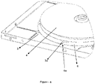
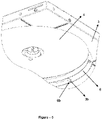
Figure 1 is an exploded view of the heating device according to the present invention. -
Figure 2 is a perspective view of a carrier plate in the heating device according to the present invention. -
Figure 3 is a side view of the carrier plate in the heating device according to the present invention. -
Figure 4 is a perspective view of a connection detail of the carrier plate in the heating device according to the present invention. -
Figure 5 is a perspective view of another connection detail of the carrier plate in the heating device according to the present invention. - All the parts illustrated in figures are individually assigned a reference numeral and the corresponding terms of these numbers are listed below:
Heating device (C) Body (1) Electronic board (2) Switching element (2a) Cooling block (2b) Carrier plate (3) First connection member (3a) Second connection member (3b) Induction coil (4) Upper surface (5) Base plate (6) First slot (6a) Second slot (6b) - Heating devices used for heating and/or cooking the products in a vessel may comprise various heating elements for the heating process. Heating devices comprising an induction coil for the heating process are called induction heating devices. Such a heating device comprises an induction coil, as well as at least one carrier plate to which the induction coil is connected. The present invention provides an induction heating device which enables the induction coil to be connected to the carrier plate in a practical and reliable way.
- The heating device (C) according to the present invention, as illustrated in
Figures 1 -15, comprises at least one body (1); at least one carrier plate (3) located in the body (1); at least one induction coil (4) located on the carrier plate (3); at least one electronic board (2) for controlling operation of the induction coil (4); and at least one upper surface (5) located on the induction coil (4). The heating device (C) further comprises at least a first connection member (3a) located on the carrier plate (3), which has at least one vertical portion extending upward from the carrier plate (3), preferably in a vertical manner, and at least one horizontal portion located on the side of the vertical portion distal to the carrier plate (3) and preferably extending parallel to the carrier plate; at least a second connection member (3b) extending upward from the carrier plate (3), preferably in a vertical manner; at least one base plate (6), preferably in the form of a fedora, which is located in the lower part of the induction coil (4); at least a first slot (6a) in the base plate (6) suitable for accommodating the vertical portion of the first connection member (3a); and at least a second slot (6b) in the base plate (6) suitable for accommodating the second connection member (3b). - In an exemplary embodiment of the invention, while manufacturing the heating device (C), which is exemplified as a stove, the induction coil (4) is connected to the carrier plate (3) by inserting the first connection member (3a) and the second connection member (3b) into the first slot (6a) and the second slot (6b). For this process, first of all, the induction coil (4) is positioned on the carrier plate (3) at an angle such that the first slot (6a) faces the vertical portion of the first connection member (3a) and the first slot (6a) remains below (as shown in
Figure 3 ). Then, by moving the induction coil (4) to approach the first connection member (3a), the vertical portion of the first connection member (3a) is placed in the first slot (6a). Afterwards, the other upper part of the induction coil (4) is released to move downwards so that it engages the second connection member (3b) of the second slot (6b). In this position, a part of the base plate (6) around the first slot (6a) remains between the horizontal portion of the first connection member (3a) and the carrier plate (3). Thus, the movement of the induction coil (4) in the vertical axis is limited. Here, also, the movement of the induction coil (4) in horizontal axes is prevented by the placement of the vertical portion of the first connection member (3a) in the first slot (6a) and the second connection member (3b) in the second slot (6b). Thus, it is ensured that the induction coil (4) is connected to the carrier plate (3) in a practical and reliable manner. - In a preferred embodiment of the invention, there is a 180° angle between the first slot (6a) and the second slot (6b). Thus, when the induction coil (4) is positioned at an angle, with the first slot (6a) facing downwards, during the assembly of the heating device (C), the second slot (6b) faces upwards. Therefore, it is ensured that the second slot (6b) is easily fitted on the second connection member (3b).
- In another preferred embodiment of the invention, the first connection member (3a) is in the form of an inverted "L". In an alternative embodiment, the first connection member (3a) is in the form of a "T".
- In another preferred embodiment of the invention, the first connection member (3a) and/or the second connection member (3b) are in a monolithic structure with the carrier plate (3). In this embodiment, the first connection member (3a) and/or the second connection member (3b) may be formed by cutting the carrier plate (3). Yet in an alternative embodiment, the first connection member (3a) and/or the second connection member (3b) are in the form of external parts connected to the carrier plate (3). In this embodiment, the heating device (C) comprises at least one connection mechanism for connecting the first connection member (3a) and/or the second connection member (3b) to the carrier plate (3). Said connection mechanism may comprise welding or adhering.
- In another preferred embodiment of the invention, the electronic board (2) comprises at least one switching element (2a). Said switching element (2a) is connected with at least one induction coil (4) and controls the operation of the induction coil (4) to which it is connected. The electronic board (2) also comprises at least one cooling block (2b) in the form of a heat sink.
- In the heating device (C) according to the present invention, the induction coil (4) is connected to the carrier plate (3) by inserting the first connection member (3a) and the second connection member (3b) located on the carrier plate (3) into the first slot (6a) and the second slot (6b) located on the base plate (6) of the induction coil (4). Therefore, the connection process is carried out in an easy and reliable manner.
Claims (11)
- A heating device (C) comprising at least one body (1); at least one carrier plate (3) located in the body (1); at least one induction coil (4) located on the carrier plate (3); at least one electronic board (2) for controlling operation of the induction coil (4); and at least one upper surface (5) located on the induction coil (4), characterized by comprising- at least a first connection member (3a) located on the carrier plate (3), which has at least one vertical portion extending upward from the carrier plate (3) and at least one horizontal portion located on the side of the vertical portion distal to the carrier plate (3);- at least a second connection member (3b) extending upward from the carrier plate (3);- at least one base plate (6) located in the lower part of the induction coil (4);- at least a first slot (6a) in the base plate (6) suitable for accommodating the vertical portion of the first connection member (3a); and- at least a second slot (6b) in the base plate (6) suitable for accommodating the second connection member (3b).
- A heating device (C) according to claim 1, characterized in that the base plate (6) is in the form of a fedora.
- A heating device (C) according to claim 1 or 2, characterized in that the angle between the first slot (6a) and the second slot (6b) is 180°.
- A heating device (C) according to any of the preceding claims, characterized in that the first connection member (3a) is in the form of an inverted "L".
- A heating device (C) according to any of the claims 1 to 3, characterized in that the first connection member (3a) is in the form of a "T".
- A heating device (C) according to any of the preceding claims, characterized in that the first connection member (3a) and/or the second connection member (3b) are in a monolithic structure with the carrier plate (3).
- A heating device (C) according to any of the claims 1 to 5, characterized in that it comprises at least one connection mechanism for connecting the first connection member (3a) and/or the second connection member (3b) to the carrier plate (3).
- A heating device (C) according to claim 7, characterized in that the connection mechanism comprises a weld.
- A heating device (C) according to claim 7, characterized in that the connection mechanism comprises an adhesive.
- A heating device (C) according to any of the preceding claims, characterized in that the electronic board (2) comprises at least one switching element (2a).
- A heating device (C) according to any of the preceding claims, characterized in that the electronic board (2) comprises at least one cooling block (2b).
Applications Claiming Priority (1)
| Application Number | Priority Date | Filing Date | Title |
|---|---|---|---|
| TR2020/16780A TR202016780A2 (en) | 2020-10-21 | 2020-10-21 | An induction cooking appliance. |
Publications (2)
| Publication Number | Publication Date |
|---|---|
| EP3989679A1 true EP3989679A1 (en) | 2022-04-27 |
| EP3989679B1 EP3989679B1 (en) | 2025-01-15 |
Family
ID=78402047
Family Applications (1)
| Application Number | Title | Priority Date | Filing Date |
|---|---|---|---|
| EP21203140.5A Active EP3989679B1 (en) | 2020-10-21 | 2021-10-18 | An induction heating device |
Country Status (2)
| Country | Link |
|---|---|
| EP (1) | EP3989679B1 (en) |
| TR (1) | TR202016780A2 (en) |
Citations (4)
| Publication number | Priority date | Publication date | Assignee | Title |
|---|---|---|---|---|
| EP2775785A1 (en) * | 2013-03-08 | 2014-09-10 | Electrolux Appliances Aktiebolag | Induction hob |
| WO2015049602A1 (en) * | 2013-10-03 | 2015-04-09 | BSH Bosch und Siemens Hausgeräte GmbH | Hob apparatus |
| US20160057815A1 (en) * | 2014-08-22 | 2016-02-25 | General Electric Company | Induction cooking appliance and method for assembling same |
| EP3675600A1 (en) * | 2018-12-31 | 2020-07-01 | Groupe Brandt | Induction hob with means for holding a conductive cable |
-
2020
- 2020-10-21 TR TR2020/16780A patent/TR202016780A2/en unknown
-
2021
- 2021-10-18 EP EP21203140.5A patent/EP3989679B1/en active Active
Patent Citations (4)
| Publication number | Priority date | Publication date | Assignee | Title |
|---|---|---|---|---|
| EP2775785A1 (en) * | 2013-03-08 | 2014-09-10 | Electrolux Appliances Aktiebolag | Induction hob |
| WO2015049602A1 (en) * | 2013-10-03 | 2015-04-09 | BSH Bosch und Siemens Hausgeräte GmbH | Hob apparatus |
| US20160057815A1 (en) * | 2014-08-22 | 2016-02-25 | General Electric Company | Induction cooking appliance and method for assembling same |
| EP3675600A1 (en) * | 2018-12-31 | 2020-07-01 | Groupe Brandt | Induction hob with means for holding a conductive cable |
Also Published As
| Publication number | Publication date |
|---|---|
| EP3989679B1 (en) | 2025-01-15 |
| TR202016780A2 (en) | 2022-05-23 |
Similar Documents
| Publication | Publication Date | Title |
|---|---|---|
| CN102770711B (en) | Gas stoves | |
| CA2461637C (en) | Rear alignment and support system for a cooking appliance cooktop | |
| CN101574014A (en) | Method for controlling an induction cooking appliance and induction cooking appliance | |
| CN109793431A (en) | Subregion oven | |
| CN102422709A (en) | Cooking hob and method for heating cooking vessels placed on the cooking hob | |
| US20100282237A1 (en) | Front controls for gas cooking range | |
| EP3989679A1 (en) | An induction heating device | |
| JPH10238780A (en) | Cooker | |
| US20050051034A1 (en) | Appliance for deep frying and slow cooking | |
| KR200482646Y1 (en) | Height adjustment range device with a function | |
| KR200488476Y1 (en) | Thermal insulation ring for gas range | |
| US20030085222A1 (en) | Cooking appliance | |
| CN216797384U (en) | Electric oven | |
| EP3445134A1 (en) | Cooking appliance and method for operating a cooking appliance | |
| GB2486802A (en) | Induction hob with a spring and bracket | |
| CN118602445B (en) | An electromagnetic stove and its control method | |
| KR20110063928A (en) | Cooker | |
| KR20140131757A (en) | Electronic grill structure | |
| US20180283697A1 (en) | Burner Module Provided with Heat Shield and Bush, Cooker or Hob Provided Therewith and Method for Manufacture Thereof | |
| KR20240052567A (en) | Multi-coil induction griddle | |
| EP3903034B1 (en) | A cooking device | |
| EP0892584A2 (en) | Electric heater assembly for cooking range | |
| KR20210149383A (en) | Electric range with a free zone heater and method for controlling the same | |
| JP6699357B2 (en) | rice cooker | |
| CN219934058U (en) | Cooking device and cooking utensil |
Legal Events
| Date | Code | Title | Description |
|---|---|---|---|
| PUAI | Public reference made under article 153(3) epc to a published international application that has entered the european phase |
Free format text: ORIGINAL CODE: 0009012 |
|
| STAA | Information on the status of an ep patent application or granted ep patent |
Free format text: STATUS: THE APPLICATION HAS BEEN PUBLISHED |
|
| AK | Designated contracting states |
Kind code of ref document: A1 Designated state(s): AL AT BE BG CH CY CZ DE DK EE ES FI FR GB GR HR HU IE IS IT LI LT LU LV MC MK MT NL NO PL PT RO RS SE SI SK SM TR |
|
| STAA | Information on the status of an ep patent application or granted ep patent |
Free format text: STATUS: REQUEST FOR EXAMINATION WAS MADE |
|
| 17P | Request for examination filed |
Effective date: 20221021 |
|
| RBV | Designated contracting states (corrected) |
Designated state(s): AL AT BE BG CH CY CZ DE DK EE ES FI FR GB GR HR HU IE IS IT LI LT LU LV MC MK MT NL NO PL PT RO RS SE SI SK SM TR |
|
| GRAP | Despatch of communication of intention to grant a patent |
Free format text: ORIGINAL CODE: EPIDOSNIGR1 |
|
| STAA | Information on the status of an ep patent application or granted ep patent |
Free format text: STATUS: GRANT OF PATENT IS INTENDED |
|
| INTG | Intention to grant announced |
Effective date: 20240926 |
|
| GRAS | Grant fee paid |
Free format text: ORIGINAL CODE: EPIDOSNIGR3 |
|
| GRAA | (expected) grant |
Free format text: ORIGINAL CODE: 0009210 |
|
| STAA | Information on the status of an ep patent application or granted ep patent |
Free format text: STATUS: THE PATENT HAS BEEN GRANTED |
|
| AK | Designated contracting states |
Kind code of ref document: B1 Designated state(s): AL AT BE BG CH CY CZ DE DK EE ES FI FR GB GR HR HU IE IS IT LI LT LU LV MC MK MT NL NO PL PT RO RS SE SI SK SM TR |
|
| REG | Reference to a national code |
Ref country code: CH Ref legal event code: EP Ref country code: GB Ref legal event code: FG4D |
|
| REG | Reference to a national code |
Ref country code: DE Ref legal event code: R096 Ref document number: 602021024904 Country of ref document: DE |
|
| REG | Reference to a national code |
Ref country code: IE Ref legal event code: FG4D |
|
| REG | Reference to a national code |
Ref country code: NL Ref legal event code: MP Effective date: 20250115 |
|
| PG25 | Lapsed in a contracting state [announced via postgrant information from national office to epo] |
Ref country code: NL Free format text: LAPSE BECAUSE OF FAILURE TO SUBMIT A TRANSLATION OF THE DESCRIPTION OR TO PAY THE FEE WITHIN THE PRESCRIBED TIME-LIMIT Effective date: 20250115 |
|
| PG25 | Lapsed in a contracting state [announced via postgrant information from national office to epo] |
Ref country code: RS Free format text: LAPSE BECAUSE OF FAILURE TO SUBMIT A TRANSLATION OF THE DESCRIPTION OR TO PAY THE FEE WITHIN THE PRESCRIBED TIME-LIMIT Effective date: 20250415 |
|
| PG25 | Lapsed in a contracting state [announced via postgrant information from national office to epo] |
Ref country code: FI Free format text: LAPSE BECAUSE OF FAILURE TO SUBMIT A TRANSLATION OF THE DESCRIPTION OR TO PAY THE FEE WITHIN THE PRESCRIBED TIME-LIMIT Effective date: 20250115 |
|
| PG25 | Lapsed in a contracting state [announced via postgrant information from national office to epo] |
Ref country code: PL Free format text: LAPSE BECAUSE OF FAILURE TO SUBMIT A TRANSLATION OF THE DESCRIPTION OR TO PAY THE FEE WITHIN THE PRESCRIBED TIME-LIMIT Effective date: 20250115 |
|
| PG25 | Lapsed in a contracting state [announced via postgrant information from national office to epo] |
Ref country code: ES Free format text: LAPSE BECAUSE OF FAILURE TO SUBMIT A TRANSLATION OF THE DESCRIPTION OR TO PAY THE FEE WITHIN THE PRESCRIBED TIME-LIMIT Effective date: 20250115 |
|
| REG | Reference to a national code |
Ref country code: LT Ref legal event code: MG9D |
|
| PG25 | Lapsed in a contracting state [announced via postgrant information from national office to epo] |
Ref country code: IS Free format text: LAPSE BECAUSE OF FAILURE TO SUBMIT A TRANSLATION OF THE DESCRIPTION OR TO PAY THE FEE WITHIN THE PRESCRIBED TIME-LIMIT Effective date: 20250515 Ref country code: NO Free format text: LAPSE BECAUSE OF FAILURE TO SUBMIT A TRANSLATION OF THE DESCRIPTION OR TO PAY THE FEE WITHIN THE PRESCRIBED TIME-LIMIT Effective date: 20250415 |
|
| REG | Reference to a national code |
Ref country code: AT Ref legal event code: MK05 Ref document number: 1760664 Country of ref document: AT Kind code of ref document: T Effective date: 20250115 |
|
| PG25 | Lapsed in a contracting state [announced via postgrant information from national office to epo] |
Ref country code: HR Free format text: LAPSE BECAUSE OF FAILURE TO SUBMIT A TRANSLATION OF THE DESCRIPTION OR TO PAY THE FEE WITHIN THE PRESCRIBED TIME-LIMIT Effective date: 20250115 |
|
| PG25 | Lapsed in a contracting state [announced via postgrant information from national office to epo] |
Ref country code: PT Free format text: LAPSE BECAUSE OF FAILURE TO SUBMIT A TRANSLATION OF THE DESCRIPTION OR TO PAY THE FEE WITHIN THE PRESCRIBED TIME-LIMIT Effective date: 20250515 Ref country code: LV Free format text: LAPSE BECAUSE OF FAILURE TO SUBMIT A TRANSLATION OF THE DESCRIPTION OR TO PAY THE FEE WITHIN THE PRESCRIBED TIME-LIMIT Effective date: 20250115 |
|
| PG25 | Lapsed in a contracting state [announced via postgrant information from national office to epo] |
Ref country code: BG Free format text: LAPSE BECAUSE OF FAILURE TO SUBMIT A TRANSLATION OF THE DESCRIPTION OR TO PAY THE FEE WITHIN THE PRESCRIBED TIME-LIMIT Effective date: 20250115 Ref country code: GR Free format text: LAPSE BECAUSE OF FAILURE TO SUBMIT A TRANSLATION OF THE DESCRIPTION OR TO PAY THE FEE WITHIN THE PRESCRIBED TIME-LIMIT Effective date: 20250416 |
|
| PG25 | Lapsed in a contracting state [announced via postgrant information from national office to epo] |
Ref country code: AT Free format text: LAPSE BECAUSE OF FAILURE TO SUBMIT A TRANSLATION OF THE DESCRIPTION OR TO PAY THE FEE WITHIN THE PRESCRIBED TIME-LIMIT Effective date: 20250115 |
|
| PG25 | Lapsed in a contracting state [announced via postgrant information from national office to epo] |
Ref country code: SE Free format text: LAPSE BECAUSE OF FAILURE TO SUBMIT A TRANSLATION OF THE DESCRIPTION OR TO PAY THE FEE WITHIN THE PRESCRIBED TIME-LIMIT Effective date: 20250115 |
|
| PG25 | Lapsed in a contracting state [announced via postgrant information from national office to epo] |
Ref country code: SM Free format text: LAPSE BECAUSE OF FAILURE TO SUBMIT A TRANSLATION OF THE DESCRIPTION OR TO PAY THE FEE WITHIN THE PRESCRIBED TIME-LIMIT Effective date: 20250115 |
|
| PG25 | Lapsed in a contracting state [announced via postgrant information from national office to epo] |
Ref country code: DK Free format text: LAPSE BECAUSE OF FAILURE TO SUBMIT A TRANSLATION OF THE DESCRIPTION OR TO PAY THE FEE WITHIN THE PRESCRIBED TIME-LIMIT Effective date: 20250115 |
|
| REG | Reference to a national code |
Ref country code: DE Ref legal event code: R097 Ref document number: 602021024904 Country of ref document: DE |
|
| PG25 | Lapsed in a contracting state [announced via postgrant information from national office to epo] |
Ref country code: CZ Free format text: LAPSE BECAUSE OF FAILURE TO SUBMIT A TRANSLATION OF THE DESCRIPTION OR TO PAY THE FEE WITHIN THE PRESCRIBED TIME-LIMIT Effective date: 20250115 Ref country code: EE Free format text: LAPSE BECAUSE OF FAILURE TO SUBMIT A TRANSLATION OF THE DESCRIPTION OR TO PAY THE FEE WITHIN THE PRESCRIBED TIME-LIMIT Effective date: 20250115 |
|
| PG25 | Lapsed in a contracting state [announced via postgrant information from national office to epo] |
Ref country code: RO Free format text: LAPSE BECAUSE OF FAILURE TO SUBMIT A TRANSLATION OF THE DESCRIPTION OR TO PAY THE FEE WITHIN THE PRESCRIBED TIME-LIMIT Effective date: 20250115 |
|
| PG25 | Lapsed in a contracting state [announced via postgrant information from national office to epo] |
Ref country code: SK Free format text: LAPSE BECAUSE OF FAILURE TO SUBMIT A TRANSLATION OF THE DESCRIPTION OR TO PAY THE FEE WITHIN THE PRESCRIBED TIME-LIMIT Effective date: 20250115 |
|
| PLBE | No opposition filed within time limit |
Free format text: ORIGINAL CODE: 0009261 |
|
| STAA | Information on the status of an ep patent application or granted ep patent |
Free format text: STATUS: NO OPPOSITION FILED WITHIN TIME LIMIT |
|
| 26N | No opposition filed |
Effective date: 20251016 |
|
| PGFP | Annual fee paid to national office [announced via postgrant information from national office to epo] |
Ref country code: DE Payment date: 20251021 Year of fee payment: 5 |
|
| PGFP | Annual fee paid to national office [announced via postgrant information from national office to epo] |
Ref country code: IT Payment date: 20251024 Year of fee payment: 5 |
|
| PGFP | Annual fee paid to national office [announced via postgrant information from national office to epo] |
Ref country code: FR Payment date: 20251030 Year of fee payment: 5 |
|
| PGFP | Annual fee paid to national office [announced via postgrant information from national office to epo] |
Ref country code: TR Payment date: 20251017 Year of fee payment: 5 |