EP3989532B1 - Imaging system, imaging method, control device, computer program, and recording medium - Google Patents
Imaging system, imaging method, control device, computer program, and recording medium Download PDFInfo
- Publication number
- EP3989532B1 EP3989532B1 EP19933805.4A EP19933805A EP3989532B1 EP 3989532 B1 EP3989532 B1 EP 3989532B1 EP 19933805 A EP19933805 A EP 19933805A EP 3989532 B1 EP3989532 B1 EP 3989532B1
- Authority
- EP
- European Patent Office
- Prior art keywords
- imaging
- image
- iris
- point
- camera
- Prior art date
- Legal status (The legal status is an assumption and is not a legal conclusion. Google has not performed a legal analysis and makes no representation as to the accuracy of the status listed.)
- Active
Links
Images





Classifications
-
- A—HUMAN NECESSITIES
- A61—MEDICAL OR VETERINARY SCIENCE; HYGIENE
- A61B—DIAGNOSIS; SURGERY; IDENTIFICATION
- A61B5/00—Measuring for diagnostic purposes; Identification of persons
- A61B5/117—Identification of persons
- A61B5/1171—Identification of persons based on the shapes or appearances of their bodies or parts thereof
-
- A—HUMAN NECESSITIES
- A61—MEDICAL OR VETERINARY SCIENCE; HYGIENE
- A61B—DIAGNOSIS; SURGERY; IDENTIFICATION
- A61B5/00—Measuring for diagnostic purposes; Identification of persons
- A61B5/103—Measuring devices for testing the shape, pattern, colour, size or movement of the body or parts thereof, for diagnostic purposes
- A61B5/11—Measuring movement of the entire body or parts thereof, e.g. head or hand tremor or mobility of a limb
- A61B5/1113—Local tracking of patients, e.g. in a hospital or private home
-
- G—PHYSICS
- G03—PHOTOGRAPHY; CINEMATOGRAPHY; ANALOGOUS TECHNIQUES USING WAVES OTHER THAN OPTICAL WAVES; ELECTROGRAPHY; HOLOGRAPHY
- G03B—APPARATUS OR ARRANGEMENTS FOR TAKING PHOTOGRAPHS OR FOR PROJECTING OR VIEWING THEM; APPARATUS OR ARRANGEMENTS EMPLOYING ANALOGOUS TECHNIQUES USING WAVES OTHER THAN OPTICAL WAVES; ACCESSORIES THEREFOR
- G03B15/00—Special procedures for taking photographs; Apparatus therefor
-
- G—PHYSICS
- G03—PHOTOGRAPHY; CINEMATOGRAPHY; ANALOGOUS TECHNIQUES USING WAVES OTHER THAN OPTICAL WAVES; ELECTROGRAPHY; HOLOGRAPHY
- G03B—APPARATUS OR ARRANGEMENTS FOR TAKING PHOTOGRAPHS OR FOR PROJECTING OR VIEWING THEM; APPARATUS OR ARRANGEMENTS EMPLOYING ANALOGOUS TECHNIQUES USING WAVES OTHER THAN OPTICAL WAVES; ACCESSORIES THEREFOR
- G03B19/00—Cameras
- G03B19/02—Still-picture cameras
- G03B19/04—Roll-film cameras
- G03B19/07—Roll-film cameras having more than one objective
-
- G—PHYSICS
- G06—COMPUTING OR CALCULATING; COUNTING
- G06T—IMAGE DATA PROCESSING OR GENERATION, IN GENERAL
- G06T1/00—General purpose image data processing
-
- G—PHYSICS
- G06—COMPUTING OR CALCULATING; COUNTING
- G06T—IMAGE DATA PROCESSING OR GENERATION, IN GENERAL
- G06T7/00—Image analysis
- G06T7/70—Determining position or orientation of objects or cameras
-
- G—PHYSICS
- G06—COMPUTING OR CALCULATING; COUNTING
- G06V—IMAGE OR VIDEO RECOGNITION OR UNDERSTANDING
- G06V40/00—Recognition of biometric, human-related or animal-related patterns in image or video data
- G06V40/10—Human or animal bodies, e.g. vehicle occupants or pedestrians; Body parts, e.g. hands
- G06V40/16—Human faces, e.g. facial parts, sketches or expressions
- G06V40/161—Detection; Localisation; Normalisation
- G06V40/166—Detection; Localisation; Normalisation using acquisition arrangements
-
- G—PHYSICS
- G06—COMPUTING OR CALCULATING; COUNTING
- G06V—IMAGE OR VIDEO RECOGNITION OR UNDERSTANDING
- G06V40/00—Recognition of biometric, human-related or animal-related patterns in image or video data
- G06V40/10—Human or animal bodies, e.g. vehicle occupants or pedestrians; Body parts, e.g. hands
- G06V40/18—Eye characteristics, e.g. of the iris
- G06V40/19—Sensors therefor
-
- H—ELECTRICITY
- H04—ELECTRIC COMMUNICATION TECHNIQUE
- H04N—PICTORIAL COMMUNICATION, e.g. TELEVISION
- H04N23/00—Cameras or camera modules comprising electronic image sensors; Control thereof
- H04N23/45—Cameras or camera modules comprising electronic image sensors; Control thereof for generating image signals from two or more image sensors being of different type or operating in different modes, e.g. with a CMOS sensor for moving images in combination with a charge-coupled device [CCD] for still images
-
- H—ELECTRICITY
- H04—ELECTRIC COMMUNICATION TECHNIQUE
- H04N—PICTORIAL COMMUNICATION, e.g. TELEVISION
- H04N23/00—Cameras or camera modules comprising electronic image sensors; Control thereof
- H04N23/60—Control of cameras or camera modules
- H04N23/61—Control of cameras or camera modules based on recognised objects
- H04N23/611—Control of cameras or camera modules based on recognised objects where the recognised objects include parts of the human body
-
- H—ELECTRICITY
- H04—ELECTRIC COMMUNICATION TECHNIQUE
- H04N—PICTORIAL COMMUNICATION, e.g. TELEVISION
- H04N23/00—Cameras or camera modules comprising electronic image sensors; Control thereof
- H04N23/60—Control of cameras or camera modules
- H04N23/667—Camera operation mode switching, e.g. between still and video, sport and normal or high- and low-resolution modes
-
- H—ELECTRICITY
- H04—ELECTRIC COMMUNICATION TECHNIQUE
- H04N—PICTORIAL COMMUNICATION, e.g. TELEVISION
- H04N23/00—Cameras or camera modules comprising electronic image sensors; Control thereof
- H04N23/60—Control of cameras or camera modules
- H04N23/67—Focus control based on electronic image sensor signals
-
- H—ELECTRICITY
- H04—ELECTRIC COMMUNICATION TECHNIQUE
- H04N—PICTORIAL COMMUNICATION, e.g. TELEVISION
- H04N23/00—Cameras or camera modules comprising electronic image sensors; Control thereof
- H04N23/90—Arrangement of cameras or camera modules, e.g. multiple cameras in TV studios or sports stadiums
-
- G—PHYSICS
- G06—COMPUTING OR CALCULATING; COUNTING
- G06T—IMAGE DATA PROCESSING OR GENERATION, IN GENERAL
- G06T2207/00—Indexing scheme for image analysis or image enhancement
- G06T2207/30—Subject of image; Context of image processing
- G06T2207/30196—Human being; Person
- G06T2207/30201—Face
Definitions
- This disclosure relates to a technical field of an imaging system, an imaging method, a control apparatus, a computer program and a recording medium that are configured to capture an image of an imaging target.
- An iris authentication system that performs an iris authentication by capturing an image of an iris of a target person that is one example of an imaging target is known as one example of an imaging system that is configured to capture an image of the imaging target.
- a Patent Literature 1 discloses an iris authentication in a walk-through type that is configured to enable the iris authentication even when the target person does not stop.
- the Patent Literature 1 discloses the iris authentication system that is provided with a wide angle camera and a plurality of iris cameras and that selects, from the plurality of iris cameras, the iris camera that should be used for the authentication by processing an image of the wide angle camera.
- Patent Literatures 2 and 3 as a background art document relating to this disclosure.
- JP 2006 163683 A MATSUSHITA ELECTRIC IND CO LTD, 22 June 2006 -06-22, discloses a system and method where a wide angle camera images an approaching person; from the position of the eyes, a direction is predicted for a second camera to focus on the eyes of the person for authentication.
- the iris authentication system disclosed in the Patent Literature 1 has such a technical problem that there is a possibility that it is not able to capture the image of the moving target person properly by using the iris camera.
- the iris authentication system that is provided with the wide angle camera and the plurality of iris cameras is required to select the iris camera that should be used for the authentication (furthermore, set a parameter of the selected iris camera, if needed) before the moving target person reaches a focus position of the iris camera.
- the iris authentication system capture the image of the target person by using the wide angle camera before the moving target person reaches the focus position of the iris camera and select the iris camera that should be used for the authentication on the basis of the image of the wide angle camera.
- the Patent Literature 1 does not consider this point.
- an example object of this disclosure is to provide an imaging system, an imaging method, a control apparatus, a computer program and a recording medium that can solve the above described technical problem.
- an example object of this disclosure is to provide an imaging system, an imaging method, a control apparatus, a computer program and a recording medium that can capture an image of a moving imaging target properly.
- a first example aspect of an imaging system for solving the technical problem is provided with: a first imaging apparatus that captures an image of an imaging target that is located at a first point; a second imaging apparatus a focus position of which is set at a second point that is located at a forward side along a moving direction of the imaging target than the first point; and a control apparatus that controls the second imaging apparatus to capture an image of the imaging target that is located at the second point on the basis of the image captured by the first imaging apparatus.
- a second example aspect of an imaging system for solving the technical problem is provided with: an imaging apparatus a state of which is switchable between a first state and a second state, that captures an image of an imaging target that is located at a first point in the first state, and that captures an image of the imaging target that is located at a second point, which is located at a forward side along a moving direction of the imaging target than the first point, in the second state; and a control apparatus that switches the imaging apparatus from the first state to the second state by controlling the imaging apparatus on the basis of the image captured by the imaging apparatus in the first state.
- a first example aspect of an imaging method for solving the technical problem includes: an obtaining step that obtains an image captured by a first imaging apparatus that captures an image of an imaging target that is located at a first point; and a controlling step that controls, on the basis of the image obtained at the obtaining step, a second imaging apparatus a focus position of which is set at a second point to capture an image of the imaging target located at the second point that is located at a forward side along a moving direction of the imaging target than the first point.
- a second example aspect of an imaging method for solving the technical problem includes: an obtaining step that obtains an image captured by an imaging apparatus in a first state from the imaging apparatus a state of which is switchable between the first state and a second state, that captures an image of an imaging target that is located at a first point in the first state, and that captures an image of the imaging target that is located at a second point, which is located at a forward side along a moving direction of the imaging target than the first point, in the second state; and a controlling step that switches the imaging apparatus from the first state to the second state by controlling the imaging apparatus on the basis of the image obtained at the obtaining step.
- a first example aspect of a control apparatus for solving the technical problem is provided with: an obtaining unit that obtains an image captured by a first imaging apparatus that captures an image of an imaging target that is located at a first point; and a controlling unit that controls, on the basis of the image obtained by the obtaining unit, a second imaging apparatus a focus position of which is set at a second point to capture an image of the imaging located at the second point that is located at a forward side along a moving direction of the imaging target than the first point.
- a second example aspect of a control apparatus for solving the technical problem is provided with: an obtaining unit that obtains an image captured by an imaging apparatus in a first state from the imaging apparatus a state of which is switchable between the first state and a second state, that captures an image of an imaging target that is located at a first point in the first state, and that captures an image of the imaging target that is located at a second point, which is located at a forward side along a moving direction of the imaging target than the first point, in the second state; and a controlling unit that switches the imaging apparatus from the first state to the second state by controlling the imaging apparatus on the basis of the image obtained by the obtaining unit.
- One example aspect of a computer program for solving the technical problem allows a computer to perform the first or second example aspect of the imaging method described above.
- each of the imaging system, the imaging method, the control apparatus, the computer program and the recording medium described above it is possible to capture an image of a moving imaging target properly.
- the iris authentication system 1 performs an iris authentication operation for performing an authentication of an authentication target person T on the basis of a pattern of an iris of the authentication target person T that is one example of an imaging target.
- the iris authentication system 1 may be used as a part of a system for automating an immigration procedure in an airport (what we call ABC (Automated Border Control)).
- the iris authentication system 1 may be an iris authentication system in a walk-through type that performs the authentication of moving authentication target person T.
- the iris authentication system 1 is the iris authentication system in the walk-through type.
- the iris authentication system 1 is not limited to the iris authentication system that is described in this paragraph as one example, and may be used as any iris authentication system that is configured to perform the authentication of the authentication target person T.
- the iris authentication system 1 is one example of an "imaging system" in a supplementary note described below.
- FIG. 1 is a block diagram that illustrates the entire configuration of the iris authentication system 1 in the present example embodiment.
- the wide camera 2 captures the image of the authentication target person T with a range of the field of view that is wider than the range of the field of view of each iris camera 3.
- the range of the field of view of the wide camera 2 is wider than the range of the field of view of each iris camera 3.
- the range of the field of view of the wide camera 2 is set to be a proper range so that the wide camera 2 is configured to capture the image of the authentication target person T regardless of the height of the authentication target person T.
- the range of the field of view of the wide camera 2 is set to be a proper range so that the wide camera 2 is configured to capture the image of the relatively tall authentication target person T and to capture the image of the relatively short authentication target person T too.
- the "range of the field of view of the camera” in the present example embodiment means a range including a scene an image of which is capturable by the camera, and may be referred to as an "imaging range".
- a size of the range of the field of view typically becomes wider as an angle of view (in other word, a view angle) of the camera becomes wider.
- an optical system (for example, a lens) of the wide camera 2 is typically an optical system that has a field of view wider than that of an optical system of each iris camera 3. Namely, an angle of view of the wide camera 2 is wider than an angle of view of each iris camera 3.
- the angle of view of the camera typically becomes wider as a focal length of an optical system (for example, a lens) of the camera becomes shorter.
- a focal length of the optical system of the wide camera 2 is shorter than a focal length of the optical system of each iris camera 3.
- the wide camera 2 captures the image of the authentication target person T that is located at a trigger point P1.
- the range of the field of view of the wide camera 2 is set to be a proper range so that the wide camera 2 is configured to capture the image of the authentication target person T that is located at the trigger point P1.
- the trigger point P1 is a point that is located on a moving route of the authentication target person T.
- the trigger point P1 is a point that is located at a nearer side than a reference point P0 as seen from the authentication target person T moving toward the trigger point P1.
- the trigger point P1 is a point that is located at a backward side (namely, a rear side) than the reference point P0 along a moving direction of the authentication target person T.
- the trigger point P1 is a point that is away from the reference point P0 by a distance D1 along the moving direction of the authentication target person T.
- the reference point P0 may be a point at which each iris camera 3 is disposed, for example.
- the reference point P0 may be a destination for the moving authentication target person T, for example.
- the destination may be a point through which the authentication target person T passes after the authentication (for example, a point at which a gate is disposed in the airport).
- the authentication target person T moves from a left side to a right side on a paper. Therefore, in the example illustrated in FIG. 2 , the trigger point P1 is a point that is away from the reference point P0 toward the left side on the paper by the distance D1. Note that the authentication target person T may move along a linear route in which the moving direction is always the same, or may move along a route (for example, a curved route or a winding route) in which the driving direction changes in the middle.
- the wide camera 2 be disposed so that a focus position of the wide camera 2 is located at the trigger point P1.
- the "focus position" in the present example embodiment means a certain area that ranges in front and back of a best focus position (for example, an area that is allowed to be regarded as in focus and corresponds to a depth of field).
- the wide camera 2 be disposed so that the focus position of the wide camera 2 is an area including the trigger point P1 (namely, so that the trigger point P1 is located in an area corresponding to the focus position).
- the trigger point P1 is set at the focus position of the wide camera 2.
- the wide camera 2 has a resolution that allows a face of the authentication target person T located at the trigger point P1 to be recognized from a wide image 200 that is an image captured by the wide camera 2. Especially, the wide camera 2 has a resolution that allows a position in the wide image 200 of the target portion TP (namely, the eye) of the authentication target person T located at the trigger point P1 to be recognized from the wide image 200.
- the distance D2 between the focus point P2 and the reference point P0 is shorter than the distance D1 between the trigger point P1 and the reference point P0.
- the focus point P2 is located at a forward side (namely, a front side) than the trigger point P1 along the moving direction of the authentication target person T.
- the trigger point P1 is located at a backward side (namely, a rear side) than the focus point P2 along the moving direction of the authentication target person T. Therefore, the moving authentication target person T passes through the focus point P2 after passing through the trigger point P1.
- the moving authentication target person T passes through the trigger point P1 before passing through the focus point P2.
- the distances D1 and D2 may be set to be any values as long as a relationship that the distance D2 is shorter than the distance D1 is satisfied.
- the distances D1 and D2 may be set 3m and 2m, respectively.
- Each iris camera 3 is disposed so that a focus position of each iris camera 3 is located at the focus point P2. Specifically, it can be said that each iris camera 3 is disposed so that the focus position of each iris camera 3 is an area including the focus point P2 (namely, so that the focus point P2 is located in an area corresponding to the focus position). Conversely, the focus point P2 is set at the focus position of each iris camera 3.
- the angle of view of the wide camera 2 is wider than the angle of view of each iris camera 3 (namely, the focal length of the optical system of the wide camera 2 is shorter than the focal length of the optical system of each iris camera 3) as described above, the area corresponding to the focus position of the wide camera 2 is wider than the area corresponding to the focus position of each iris camera 3.
- the plurality of iris cameras 3 are disposed so that the ranges of the field of view of the plurality of iris cameras 3 overlap partially in a vertical direction (alternatively, a desired direction that is different from the vertical direction) at the focus point P2.
- scenes that are partially the same are included in two images respectively captured by two iris cameras 2 the range of the field of view of which overlap partially.
- the same scene is included in a lower end part of the image captured by the iris camera 3-k and an upper end part of the image captured by the iris camera 3-m.
- the plurality of iris cameras 3 are disposed so that a combined range of field of view that is obtained by combining the ranges of the field of view of the plurality of iris cameras 3 has a predetermined horizontal size in a horizontal direction and has a predetermined vertical size in the vertical direction.
- the predetermined horizontal size may be a size (for example, 0.2m) that allows the target portion TP of the authentication target person T located at the focus point P2 to be included in the combined range of the field of view.
- the predetermined vertical size may be a size (for example, 0.4m) that allows the target portion TP of the authentication target person T located at the focus point P2 to be included in the combined range of the field of view regardless of the height of the authentication target person T.
- Each iris camera 3 has a resolution that allows the target portion TP of the authentication target person T located at the focus point P2 to be recognized from an iris image 300 that is an image captured by each iris camera 3. Especially, each iris camera 3 has a resolution that allows the pattern of the iris of the authentication target person T located at the focus point P2 to be recognized from the iris image 300 that is the image captured by each iris camera 3.
- both of the authentication target person T (especially, the target portion TP) located at the trigger point P1 and the authentication target person T (especially, the target portion TP) located at the focus point P2 may be included in the range of the field of view of the wide camera 2.
- both of the authentication target person T (especially, the target portion TP) located at the trigger point P1 and the authentication target person T (especially, the target portion TP) located at the focus point P2 may be included in the range of the field of view of each iris camera 3.
- the range or the field of view of the wide camera 2 may not overlap with the range of the field of view of each of the plurality of iris cameras.
- the authentication target person T (especially, the target portion TP) located at the trigger point P1 may be included in the range of the field of view of the wide camera 2 and the authentication target person T (especially, the target portion TP) located at the focus point P2 may not be included in the range of the field of view of the wide camera 2.
- the authentication target person T (especially, the target portion TP) located at the focus point P2 may be included in the range of the field of view of each iris camera 3 and the authentication target person T (especially, the target portion TP) located at the trigger point P1 may not be included in the range of the field of view of each iris camera 3.
- the human detection sensor 4 is a detection apparatus for detecting whether or not the authentication target person T is located at the trigger point P1.
- a detected result by the human detection sensor 4 is outputted to the iris authentication apparatus 6.
- the detected result by the human detection sensor 4 is used as a condition to determine whether or not the wide camera 2 captures the image of the authentication target person T located at the trigger point P1.
- the human detection sensor 5 is a detection apparatus for detecting whether or not the authentication target person T is located at the focus point P2. A detected result by the human detection sensor 5 is outputted to the iris authentication apparatus 6. The detected result by the human detection sensor 5 is used as a condition to determine whether or not the iris camera 3 captures the image of the authentication target person T located at the focus point P2.
- the iris authentication apparatus 6 controls an entire operation of the iris authentication system 1. Especially in the present example embodiment, the iris authentication apparatus 6 performs an iris authentication operation.
- the iris authentication operation is an operation that includes a process of selecting one iris camera 3 for capturing the image of the authentication target person T located at the focus point P2 from the plurality of iris cameras 3 on the basis of the wide image 200 captured by the wide camera 2 and a process of performing the authentication of the authentication target person T on the basis of the iris image 300 captured by the selected one iris camera 3, for example.
- FIG. 3 is a block diagram that illustrates a hardware configuration of the iris authentication apparatus 6 in the present example embodiment.
- the iris authentication apparatus 6 is provided with a CPU (Central Processing Unit) 61, a RAM (Random Access Memory) 62, a ROM (Read Only Memory) 63, a storage apparatus 64, an input apparatus 65, and an output apparatus 66.
- the CPU 61, the RAM 62, the ROM 63, the storage apparatus 64, the input apparatus 65, and the output apparatus 66 are interconnected through a data bus 67.
- the iris authentication apparatus 6 may not be provided with at least one of the RAM 62, the ROM 63, the storage apparatus 64, the input apparatus 65, and the output apparatus 66.
- the CPU 61 reads a computer program.
- the CPU 61 may read a computer program stored in at least one of the RAM 62, the ROM 63 and the storage apparatus 64.
- the CPU 61 may read a computer program stored in a computer-readable recording medium, by using a not-illustrated recording medium reading apparatus.
- the CPU 61 may obtain (namely, read) a computer program from a not-illustrated apparatus disposed outside the iris authentication apparatus 6, through a network interface.
- the CPU 61 controls the RAM 62, the storage apparatus 64, the input apparatus 65, and the output apparatus 66 by executing the read computer program.
- a logical functional block(s) for performing the iris authentication operation is implemented in the CPU 61.
- the CPU 61 is configured to function as a controller for implementing the logical block for performing the iris authentication operation.
- FIG. 4 One example of the logical block that is implemented in the CPU 61 for performing the iris authentication operation is illustrated in FIG. 4 .
- an image obtaining unit 611 that is one specific example of a "obtaining unit” in the supplementary note described below
- an area detection unit 612 that is one specific example of a "controlling unit” in the supplementary note described below
- a coordinate estimation unit 613 that is one specific example of the "controlling unit” in the supplementary note described below
- a camera set unit 614 that is one specific example of the "controlling unit” in the supplementary note described below
- an imaging control unit 615 that is one specific example of the "controlling unit” in the supplementary note described below
- an authentication unit 616 are implemented as logical blocks for performing the iris authentication operation.
- the RAM 62 temporarily stores the computer program to be executed by the CPU 61.
- the RAM 62 temporarily stores the data that is temporarily used by the CPU 61 when the CPU 61 executes the computer program.
- the RAM 62 may be, for example, a D-RAM (Dynamic RAM).
- the ROM 63 stores the computer program to be executed by the CPU 61.
- the ROM 63 may otherwise store fixed data.
- the ROM 63 may be, for example, a P-ROM (Programmable ROM).
- the storage apparatus 64 stores the data that is stored for a long term by the iris authentication apparatus 6.
- the storage apparatus 64 may operate as a temporary storage apparatus of the CPU 61.
- the storage apparatus 64 may include, for example, at least one of a hard disk apparatus, a magneto-optical disk apparatus, an SSD (Solid State Drive), and a disk array apparatus.
- the input apparatus 65 is an apparatus that receives an input instruction from a user of the iris authentication apparatus 6.
- the input apparatus 65 may include, for example, at least one of a keyboard, a mouse, and a touch panel.
- the output apparatus 66 is an apparatus that outputs an information about the iris authentication apparatus 6, to the outside.
- the output apparatus 66 may be a display apparatus that is configured to display an information about the iris authentication apparatus 6.
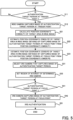
- FIG. 5 is a flow chart that illustrates the flow of the operation (namely, the iris authentication operation) of the iris authentication system 1 in the present example embodiment.
- the imaging control unit 615 determines whether or not the authentication target person T is located at the trigger point P1 on the basis of the detected result by the human detection sensor 4 (a step S11). As a result of the determination at the step S11, when it is determined that the authentication target person T is not located at the trigger point P1 (the step S11: No), the process at the step S11 is repeatedly performed. On the other hand, as a result of the determination at the step S11, when it is determined that the authentication target person T is located at the trigger point P1 (the step S11: Yes), the imaging control unit 615 controls the wide camera 2 to capture the image of the authentication target person T located at the trigger point P1 (a step S12). As a result, the wide camera 2 captures the image of the authentication target person T located at the trigger point P1 (the step S12). The wide image 200 captured by the wide camera 2 is obtained by the image obtaining unit 611 (the step S12).
- the area detection unit 612 detects, as a target area TA, an image part of the wide image 200 in which the target portion TP is included by performing an image processing on the wide image 200 obtained at the step S12 (a step S21). For example, as illustrated in FIG. 6 that is a planar view illustrating one example of the target area TA in the wide image 200, the area detection unit 612 detects, as the target area TA, a rectangular (alternatively, another shaped) image part of the wide image 200 in which the target portion TP is included. Furthermore, the area detection unit 612 calculates a position coordinate C of the detected target area TA in the wide image 200 (the step S21).
- the position coordinate C may include a coordinate of a desired part (for example, a corner part) of the target area TA.
- the position coordinate C is typically a two-dimensional coordinate (alternatively, a two-dimensional vector). Note that the position coordinate C that is calculated at the step S21 is referred to as a "position coordinate C(wide:P1)" in the below described description for convenience of description.
- the coordinate estimation unit 613 estimates, on the basis of the position coordinate C(wide:P1) of the target area TA that is calculated at the step S21, the position coordinate C of the target area TA in the wide image 200 that is obtained under the assumption that the wide camera 2 has captured the image of the authentication target person T that is located at the focus point P2 (a step S22). More specifically, the coordinate estimation unit 613 estimates the position coordinate C of the target area TA in the wide image 200 that is expected to be obtained under the assumption that the wide camera 2 has captured the image of the authentication target person T that has moved from the trigger point P1 to the focus point P2 (the step S22).
- the coordinate estimation unit 613 estimates the position coordinate C of the target area TA in the wide image 200 that is expected to be obtained under the assumption that the wide camera 2 has captured the image of the authentication target person T that is located at the focus point P2 in a situation where the authentication target person T located at the trigger point P1 has moved to the focus point P2 (the step S22).
- the position coordinate C that is estimated at the step S22 is referred to as a "position coordinate C(wide:P2)" in the below described description for convenience of description.
- the wide image 200 that is actually obtained by means of the wide camera 2 capturing the image of the authentication target person T located at the trigger point P1 is referred to as a "wide image 200(P1)” and the wide image 200 that is expected to be obtained under the assumption that the wide camera 2 has captured the image of the authentication target person T that has moved from the trigger point P1 to the focus point P2 is referred to as a "wide image 200(P2)" to distinguish the both, for convenience of description.
- the trigger point P 1 is different from the focus point P2
- at least one of a size and a position of the authentication target person T in the wide image 200(P 1) is different from at least one of a size and a position of the authentication target person T in the wide image 200(P2), as illustrated in FIG. 6 that illustrates the wide image 200(P1) and FIG. 7 that illustrates the wide image 200(P2).
- at least one of the size and the position of the authentication target person T in the wide image 200(P1) is even more different from at least one of the size and the position of the authentication target person T in the wide image 200(P2), as the trigger point P1 is away from the focus point P2 more.
- the position coordinate C(wide:P1) is different from the position coordinate C(wide:P2).
- the coordinate estimation unit 613 may estimate the position coordinate C(wide:P2) from the position coordinate C(wide:P1) by using a first correspondence information that indicates a correspondence (typically, a positional relationship) between an object included in the wide image 200(P1) and the same object included in the wide image 200(P2).
- This first correspondence information typically indicates a correspondence between a position coordinate in the wide image 200(P1) of the object included in the wide image 200(P1) and a position coordinate in the wide image 200(P2) of the same object included in the wide image 200(P2) that is expected to be obtained when the object has moved from the trigger point P1 to the focus point P2 as with the authentication target person T.
- the first correspondence information is substantially information to which a moving aspect of the authentication target person T (for example, a moving direction of the authentication target person T) is reflected.
- the first correspondence information substantially information relating to the moving aspect of the authentication target person T (for example, the moving direction of the authentication target person T).
- the first correspondence information may be calculated in advance (for example, before the iris authentication operation is performed) on the basis of the wide image 200 that is obtained by means of the wide camera 2 actually capturing the image of the object located at the trigger point P1 and the wide image 200 that is obtained by means of the wide camera 2 actually capturing the image of the same object that has moved from the trigger point P1 to the focus point P2 as with the authentication target person T.
- the first correspondence information may be calculated on the basis of the position coordinate in the wide range 200 of the object located at the trigger point P1 and the position coordinate in the wide range 200 of the object located at the focus point P2.
- the wide image 200 that is expected to be obtained when the wide camera 2 captures the image of the object located at the trigger point P1 and the wide image 200 that is expected to be obtained when the wide camera 2 captures the image of the object that has moved from the trigger point P1 to the focus point P2 as with the authentication target person T may be calculated by a simulation and the like, and the first correspondence information may be calculated on the basis of a result of the simulation in advance. In the simulation, at least one of a position of the wide camera 2, a camera parameter of the wide camera 2, a position of the trigger point P1 and a position of the focus point P2 may be considered. Alternatively, the first correspondence information may be calculated by any other method.
- a first transformation matrix H1 that transforms the position coordinate C(wide:P1) to the position coordinate C(wide:P2) is one example of the first correspondence information.
- This first transformation matrix H1 may be a matrix that represents a projective transformation to project an object located at the trigger point P1 onto a virtual plane located at the focus point P2, for example.
- the coordinate estimation unit 613 estimates, on the basis of the position coordinate C(wide:P2) that is estimated at the step S22, the position coordinates C of the target areas TA in the plurality of iris images 300 that are obtained, respectively, under the assumption that the plurality of iris cameras 3 have captured the image of the authentication target person T that is located at the focus point P2 (a step S23). More specifically, the coordinate estimation unit 613 estimates the position coordinates C of the target areas TA in the plurality of iris images 300 that are expected to be obtained, respectively, under the assumption that the plurality of iris cameras 3 have captured the image of the authentication target person T that has moved from the trigger point P1 to the focus point P2 (the step S23).
- the coordinate estimation unit 613 estimates the position coordinates C of the target areas TA in the plurality of iris images 300 that are expected to be obtained, respectively, under the assumption that the plurality of iris cameras 3 have captured the image of the authentication target person T that is located at the focus point P2 in a situation where the authentication target person T located at the trigger point P1 has moved to the focus point P2 (the step S23).
- the position coordinate C that is estimated at the step S23 is referred to as a "position coordinate C(iris:P2)" in the below described description for convenience of description.
- the iris image 300 that is expected to be obtained under the assumption that each iris camera 3 has captured the image of the authentication target person T that has moved from the trigger point P1 to the focus point P2 is referred to as an "iris image 300(P2)".
- the range of the field of view of each iris camera 3 is narrower than the range of the field of view of wide camera 2.
- the target area TA included in the wide image 200(P2) is not necessarily included in all of the plurality of iris images 300(P2).
- the plurality of iris images 300(P2) include both of the iris image 300(P2) in which the target area TA is included and the iris image 300(P2) in which the target area TA is not included.
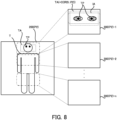
- FIG. 8 that illustrates a relationship between the wide image 200(P2) and the plurality of iris images 300
- the target area TA is included in the iris image 300(P2)-1 that is expected to be captured by the iris camera 3-1 and is not included in the iris images 300(P2)-2 to 300(P2)-n that are expected to be captured by the iris cameras 3-2 to 3-n.
- the coordinate estimation unit 613 determines, on the basis of the position coordinate C(wide:P2), the iris image 300(P2) in which the target area TA is expected to be included, and estimates the position coordinate C(iris:P2) of the target area TA in the determined iris image 300(P2).
- the coordinate estimation unit 613 may estimate the position coordinate C(iris:P2) from the position coordinate C(wide:P2) by using a second correspondence information that indicates a correspondence (typically, a positional relationship) between an object included in the wide image 200(P2) and the same object included in each of the plurality of iris images 300(P2).
- This second correspondence information typically indicates a correspondence between a position coordinate in the wide image 200(P2) of the object included in the wide image 200(P2) and a position coordinate in the iris image 300(P2) of the same object included in each of the plurality of iris images 300(P2).
- the second correspondence information may be calculated in advance (namely, before the iris authentication operation is performed) on the basis of the wide image 200 that is obtained by means of the wide camera 2 actually capturing the image of the object located at the focus point P2 and the plurality of iris images 300 that are obtained by means of the plurality of iris cameras 3 actually capturing the image of the same object that is located at the focus point P2, respectively.
- the second correspondence information may be calculated on the basis of the position coordinate in the wide range 200 of the object at the focus point P2 and the position coordinate in the iris range 300 of the object at the focus point P2.
- the wide image 200 that is expected to be obtained when the wide camera 2 captures the image of the object located at the focus point P2 and the plurality of iris images 300 that are expected to be obtained when the plurality of iris cameras 3 capture the image of the same object that is located at the focus point P2, respectively, may be calculated by a simulation and the like, and the second correspondence information may be calculated on the basis of a result of the simulation in advance.
- the simulation at least one of the position of the wide camera 2, the camera parameter of the wide camera 2, positions of the plurality of iris cameras 3, camera parameters of the plurality of iris cameras 3, the position of the trigger point P1 and the position of the focus point P2 may be considered.
- the second correspondence information may be calculated by any other method.
- a second transformation matrix H2 that transforms the position coordinate C(wide:P2) to the position coordinate C(iris:P2) is one example of the second correspondence information.
- the camera set unit 614 selects, on the basis of the position coordinate C(iris:P2) that is estimated at the step S23, one iris camera 3 for capturing the image of the authentication target person T located at the focus point P2 from the plurality of iris cameras 3 (a step S31).
- the coordinate estimation unit 613 determines, on the basis of the position coordinate C(wide:P2), the iris image 300(P2) in which the target area TA is included. Therefore, the camera set unit 614 selects, as one iris camera 3 for capturing the image of the authentication target person T located at the focus point P2, the iris camera 3 of the plurality of iris cameras 3 that corresponds to the iris image 300(P2) in which the target area TA is included.
- the camera set unit 614 selects the iris camera 3-1 that corresponds to the iris image 300(P2)-1 as one iris camera 3 for capturing the image of the authentication target person T located at the focus point P2.
- the camera set unit 614 sets a region of interest (ROI: Region of Interest) IA that defines an image part, which is actually obtained (namely, read) for performing the iris authentication, of the iris image 300 captured by one iris camera 3 selected at the step S31 (a step S32).
- ROI Region of Interest
- the camera set unit 614 sets, to the region of interest IA, a rectangular (alternatively, another shaped) area, in which the target portion TP is expected to be included, of the iris image 300 captured by selected one iris camera 3. Namely, as illustrated in FIG.
- the camera set unit 614 sets, to the region of interest IA, a rectangular (alternatively, another shaped) area, which includes the target area TA, corresponds to the target area TA or is expected to be included in the target area TA, of the iris image 300 captured by selected one iris camera 3, for example.
- the position coordinate C(iris:P2) estimated at the step S23 indicates the position coordinate of the target area TA in the iris image 300(P2). Since the target portion TP is included in the target area TA, the camera set unit 614 is able to set the region of interest IA properly on the basis of the position coordinate C(iris:P2). In the example illustrated in FIG. 8 , the camera set unit 614 sets a part of the iris image 300(P2)-1 to the region of interest IA.
- the iris authentication system 1 When the region of interest IA is set, the iris authentication system 1 operates in a region of interest mode.
- the image obtaining unit 611 obtains an image part of the iris image 300 (namely, a part of an image data of the iris image 300) in the region of interest IA, instead of obtaining whole of the iris image 300 captured by the iris camera 3.
- the image obtaining unit 611 may not obtain an image part of the iris image 300 (namely, a residual part of the image data of the iris image 300) in an area other than the region of interest IA.
- a frame rate at which the image obtaining unit 611 obtains the iris image 300 from the iris camera 3 substantially improves, compared to a case where whole of the iris image 300 is obtained.
- the frame rate improves to be the double, compared to a case where whole of the iris image 300 is obtained.
- the image obtaining unit 611 is able to obtain the iris image at the frame rate that is necessary for the iris authentication.
- the imaging control unit 615 determines whether or not the authentication target person T is located at the focus point P2 on the basis of the detected result by the human detection sensor 5 (a step S41). Namely, the imaging control unit 615 determines whether or not the authentication target person T that has been determined to be located at the trigger point P1 moves to the focus point P2 on the basis of the detected result by the human detection sensor 5 (the step S41). As a result of the determination at the step S41, when it is determined that the authentication target person T is not located at the focus point P2 (the step S41: No), the process at the step S41 is repeatedly performed.
- the imaging control unit 615 controls one iris camera 3 selected at the step S31 to capture the image of the authentication target person T located at the focus point P2 (a step S42).
- the selected one iris camera 3 captures the image of the authentication target person T located at the focus point P2 (the step S42).
- the iris image 300 captured by the selected one iris camera 3 (especially, the image part of the iris image 300 in the region of interest IA) is obtained by the image obtaining unit 611 (the step S42).
- the authentication unit 616 performs the iris authentication by using the iris image 300 obtained at the step S42 (a step S51). For example, the authentication unit 616 determines the patter of the iris of the authentication target person T on the basis of the iris image 300 obtained at the step S42. Then, the authentication unit 616 determines whether or not the determined pattern matches a pattern that is registered in a data base stored in the storage apparatus 64 and the like. When the determined pattern matches the pattern registered in the database, the authentication unit 616 determines that the authentication target person T is a proper person. When the determined pattern matches the pattern registered in the database, the authentication unit 616 determines that the authentication target person T is not a proper person.
- the wide camera 2 captures the image of the authentication target person T that is located at the trigger point P1 that is different from (specifically, is located at a backward side of) the focus point P2 before the iris camera 3 captures the image of the authentication target person T that is located at the focus point P2.
- the iris authentication system 1 is able to select one iris camera 3 for capturing the image of the authentication target person T before the authentication target person T is located at the focus point P2.
- the iris authentication system 1 is able to select one iris camera 3 for capturing the image of the authentication target person T (furthermore, setting the region of interest IA) by using a time during which the authentication target person T moves from the trigger point P1 to the focus point P2.
- the iris authentication system 1 is able to capture the image of the moving authentication target person T (especially, the target portion TP thereof) properly.
- the iris authentication system 1 is able to select one iris camera 3 for capturing the image of the authentication target person T properly on the basis of the wide image 200(P1) captured by the wide camera 2.
- the iris authentication system 1 estimates, on the basis of the position coordinate C(wide:P1) of the target area TA in the wide image 200(P2), the position coordinate C(wide:P2) of the target area TA in the wide image 200(P2) that is expected to be obtained under the assumption that the wide camera 2 has captured the image of the authentication target person T that has moved to the focus point P2, and then, estimates the position coordinate C(iris:P2) of the target area TA in the iris image 300(P2) that is expected to be obtained under the assumption that the iris camera 3 has captured the image of the authentication target person T that has moved to the focus point P2
- the position coordinate C(wide:P1) is different from the position coordinate C(wide:P2) as described above, as illustrated in FIG. 6 and FIG. 7 described above. Therefore, if the position coordinate C(wide:P1) is used as the position coordinate C(wide:P2) as it is, one iris camera 3 that is selected to capture the image of the authentication target person T is not able to capture the image of the target portion TP properly.
- the position coordinate C(wide:P1) is used as the position coordinate C(wide:P2) as it is, there is a possibility that the camera set unit 614 mistakenly selects, as one iris camera 3 for capturing the image of the authentication target person T, the iris camera 3 that is not able to capture the image of the target portion TP of the authentication target person T located at the focus point P2.
- the position coordinate C(wide:P2) is estimated from the position coordinate C(wide:P1) and then the position coordinate C(iris:P2) is estimated.
- the position coordinate C(wide:P2) is estimated from the position coordinate C(wide:P1) and then the position coordinate C(iris:P2) is estimated.
- a process of estimating the position coordinate C(wide:P2) from the position coordinate C(wide:P1) contributes a proper selection of the iris camera 3 that captures the image of the target portion TP of the authentication target person T located at the focus point P2 (namely, a proper imaging of the target portion TP by the iris camera 3).
- the plurality of human detection sensors (namely, the human detection sensors 4 and 5) that correspond to the trigger point P1 and the focus point P2, respectively, are disposed.
- the iris authentication system 1 is able to properly determine whether or not the authentication target person T is located at each of the trigger point P1 and the focus point P2. Namely, the iris authentication system 1 is able to properly capture the image of the authentication target person T that is located at the trigger point P1 by the wide camera 2 and is able to properly capture the image of the authentication target person T that is located at the focus point P2 by the iris camera 3.
- FIG. 9 is a block diagram that illustrates the entire configuration of the iris authentication system 1a in the first modified example. Note that a detailed description of a component that is same as a component of the above described iris authentication system 1 is omitted by assigning the same reference number thereto.
- the iris authentication system 1a is different from the iris authentication system 1 in that it is provided with a single common camera 7a instead of the wide camera 2 and the plurality of iris cameras 3. Another characteristic of the iris authentication system 1a may be same as another characteristic of iris authentication system 1.
- the common camera 7a is an imaging apparatus that is configured to capture the image of the authentication target person T, as with the wide camera 2 and the plurality of iris cameras 3.
- the common camera 7a is configured to switch a state thereof between a wide imaging state in which it is configured to serve as the wide camera 2 and an iris imaging state in which it is configured to serve as at least one of the plurality of iris cameras 3.
- the wide imaging state and the iris imaging state are examples of a "first state” and a "second state” in the supplementary note described below, respectively.
- the common camera 7a in the wide imaging state is equivalent to the above described wide camera 2. Namely, the common camera 7a in the wide imaging state operates as with the above described wide camera 2. Thus, a characteristic of the common camera 7a in the wide imaging state may be same as the above described wide camera 2, and thus, its detailed description is omitted.
- the common camera 7a in the iris imaging state is equivalent to at least one of the plurality of iris cameras 3 described above.
- the common camera 7a in the iris imaging state operates as with at least one of the plurality of iris cameras 3 described above.
- a characteristic of the common camera 7a in the iris imaging state may be same as at least one of the plurality of iris cameras 3 described above, and thus, its detailed description is omitted.
- the range of the field of view of the common camera 7a in the iris imaging state is typically same as the combined range of the field of view (see FIG. 2 ) that is obtained by combining the ranges of the field of view of the plurality of iris cameras 3.
- the common camera 7a in the iris imaging state is substantially equivalent to the plurality of iris cameras 3 described above that is regarded as a single camera.
- the common camera 7a may be provided with an optical system having a variable optical characteristic (for example, a focal length), for example.
- a focal length for example, the focal length of the common camera 7a in the wide imaging state is typically shorter than the focal length of the common camera 7a in the iris imaging state.
- the common camera 7a is configured to serve as the wide camera 2 and is configured to serve as at least one of the plurality of iris cameras 3.
- ROI Region of Interest
- the image captured by the common camera 7a in the wide imaging state is referred to as the "wide image 200" for convenience of description, because the image captured by the common camera 7a in the wide imaging state is substantially equivalent to the wide image 200 captured by the wide camera 2.
- the image captured by the common camera 7a in the iris imaging state is referred to as the "iris image 300" for convenience of description, because the image captured by the common camera 7a in the iris imaging state is substantially equivalent to an image that is obtained by combining the plurality of iris images 300 captured by the plurality of iris cameras 3, respectively.
- FIG. 10 is a flow chart that illustrates the flow of the operation (namely, the iris authentication operation) of the iris authentication system 1a in the first modified example. Note that a detailed description of a process that is same as a process described in the above described FIG. 5 is omitted by assigning the same step number thereto.
- the imaging control unit 615 controls the common camera 7a to capture the image of the authentication target person T located at the trigger point P1 (a step S12a). In this case, the imaging control unit 615 controls the common camera 7a so that the state of the common camera 7a becomes the wide imaging state before controlling the common camera 7a to capture the image of the authentication target person T located at the trigger point P1.
- the coordinate estimation unit 613 estimates, on the basis of the position coordinate C(wide:P1) of the target area TA that is calculated at the step S21, the position coordinate C(wide:P2) of the target area TA in the wide image 200(P2) that is expected to be obtained under the assumption that the common camera 7a in the wide imaging state has captured the image of the authentication target person T that has moved from the trigger point P1 to the focus point P2 (a step S22a).
- the coordinate estimation unit 613 may estimate the position coordinate C(wide:P2) from the position coordinate C(wide:P1) by using the first correspondence information that indicates the correspondence between the object included in the wide image 200(P1) and the same object included in the wide image 200(P2) at the step S22a, as with the above described step S22.
- the first correspondence information in the first modified example is different from the above described first correspondence information in that it is information targeting at the common camera 7a.
- the coordinate estimation unit 613 estimates, on the basis of the position coordinate C(wide:P2) that is estimated at the step S22, the position coordinate C(iris:P2) of the target area TA in the iris image 300 that is expected to be obtained under the assumption that the common camera 7a in the iris imaging state has captured the image of the authentication target person T that has moved from the trigger point P1 to the focus point P2 (a step S23a).
- the coordinate estimation unit 613 may estimate the position coordinate C(iris:P2) from the position coordinate C(wide:P2) by using the second correspondence information that indicates the correspondence between the object included in the wide image 200(P2) and the same object included in the iris image 300(P2) at the step S23a, as with the above described step S23.
- the second correspondence information in the first modified example is different from the above described second correspondence information targeting at the wide camera 2 and the iris cameras 3 in that it is information targeting at the common camera 7a in the wide imaging state and the common camera 7a in the iris imaging state (especially, the common camera 7a in the iris imaging state that is configured to capture the image of the target portion TP of the authentication target person T located at the focus point P2).
- the coordinate estimation unit 613 estimates, on the basis of the position coordinate C(wide:P2), the position coordinate C(iris:P2) of the target area TA in the iris image 300(P2) without performing a process of determining one iris image 300(P2) in which the target area TA is expected to be included from the plurality of iris images 300(P2).
- the camera set unit 614 sets, on the basis of the position coordinate C(iris:P2) that is estimated at the step S23, the region of interest (ROI: Region of Interest) IA that defines the image part, which is actually obtained (namely, read) for performing the iris authentication, of the iris image 300 captured by one common camera 7a in the iris imaging state (a step S32a).
- the process at the step S32a may be same as the process at the above described step S32 that targets the iris camera 3, except that it targets at the common camera 7a.
- the imaging control unit 615 controls the common camera 7a to capture the image of the authentication target person T located at the focus point P2 (a step S42a).
- the imaging control unit 615 controls the common camera 7a so that the state of the common camera 7a is switched from the wide imaging state to the iris imaging state before controlling the common camera 7a to capture the image of the authentication target person T located at the focus point P2.
- the imaging control unit 615 controls the common camera 7a so that the state of the common camera 7a is switched from the wide imaging state to the iris imaging state before the iris image 300 is obtained at the step S42a after the wide image 200 is obtained at the step S12a.
- the imaging control unit 615 controls the zoom lens (for example, moves the movable lens included in the zoom lens) so that the focal length of the optical system including the zoom lens is set to be the relatively long second distance. Namely, the imaging control unit 615 changes the focal length of the optical system including the zoom lens from the relatively short first distance to the relatively long second distance.
- the state of the common camera 7a is switched from the wide imaging state to the iris imaging state.
- the imaging control unit 615 controls the common camera 7a to capture the image of the authentication target person T located at the focus point P2.
- the common camera 7a captures the image of the authentication target person T located at the focus point P2 (the step S42a).
- the iris image 300 captured by the common camera 7a (especially, the image part of the iris image 300 in the region of interest IA) is obtained by the image obtaining unit 611 (the step S42a).
- the authentication unit 616 performs the iris authentication by using the iris image 300 obtained at the step S42 (the step S51).
- the iris authentication system 1a in the first modified example described above is able to achieve an effect that is same as an effect achievable by the above described iris authentication system 1.
- the coordinate estimation unit 613 estimates the position coordinate C(wide:P2) from the position coordinate C(wide:P1) and then estimates the position coordinate C(iris:P2) from the position coordinate C(wide:P2) by using two correspondence information, the first and second correspondence information.
- the coordinate estimation unit 613 may estimate the position coordinate C(iris:P2) directly from the position coordinate C(wide:P1) by using single correspondence information to which both of the first and second correspondence information are reflected (for example, single transformation matrix that corresponds to the first transformation matrix H1 ⁇ the second transformation matrix H2.
- an operation for estimating the position coordinate C(iris:P2) directly from the position coordinate C(wide:P1) is equivalent to an operation for estimating the position coordinate C(wide:P2) from the position coordinate C(wide:P1) and then estimating the position coordinate C(iris:P2) from the position coordinate C(wide:P2), as long as the firs correspondence information is reflected to the single correspondence information.
- the camera set unit 614 may not perform the process of setting the region of interest IA (the process corresponding to the step S32 of FIG. 5 or the step S32a of FIG. 10 ).
- the iris authentication system 1 may not operates in the region of interest mode.
- the image obtaining unit 611 may obtain whole of the iris image 300 captured by the iris camera 3 or the common camera 7a.
- the authentication unit 616 may perform the iris authentication by using whole of the iris image 300 captured by the iris camera 3 or the common camera 7a.
- the iris authentication apparatus 6 is provided with the image obtaining unit 611, the area detection unit 612, the coordinate estimation unit 613, the camera set unit 614, the imaging control unit 615 and the authentication unit 616.
- FIG. 11 that is a block diagram illustrating a modified example of the iris authentication apparatus 6
- the iris authentication apparatus 6 may not be provided with at least one of the area detection unit 612, the coordinate estimation unit 613 and the camera set unit 614.
- the imaging control unit 615 may perform the process that is performed by each of the area detection unit 612, the coordinate estimation unit 613 and the camera set unit 614.
- an apparatus outside the iris authentication apparatus 6 may perform the process that is performed by each of the area detection unit 612, the coordinate estimation unit 613 and the camera set unit 614. Moreover, as illustrated in FIG. 11 , the iris authentication apparatus 6 may not be provided with the authentication unit 616. In this case, an apparatus outside the iris authentication apparatus 6 may perform the process that is performed by the authentication unit 616.
- the iris authentication system 1 is provided with the human detection sensor 4.
- the iris authentication system 1 may not be provided with the human detection sensor 4.
- the wide camera 2 or the common camera 7a may keep capturing the image of the scene in the range of the field of view at a predetermined frame rate (namely, an imaging rate) regardless of whether the authentication target person T is located at the trigger point P1.
- the wide camera 2 or the common camera 7a may keep capturing the image of the scene in the range of the field of view at the predetermined frame rate during at least a period when the authentication target person T passes through the trigger point P1.
- the wide camera 2 or the common camera 7a is able to capture the image of the authentication target person T at a timing when the authentication target person T reaches the trigger point P1.
- the image obtaining unit 611 is able to obtain the wide image 200 including the authentication target person T located at the trigger point P1.
- the iris authentication apparatus 6 may determine whether or not the wide image 200 including the authentication target person T located at the trigger point P1 is obtained by performing an image analysis on the wide image 200. Namely, the iris authentication apparatus 6 may determine whether or not the authentication target person T is located at the trigger point P1 by performing the image analysis on the wide image 200.
- the iris authentication apparatus 6 When it is determined that the authentication target person T is located at the trigger point P1 (namely, the wide image 200 including the authentication target person T located at the trigger point P1 is obtained), the iris authentication apparatus 6 performs the process of selecting one iris camera 3 for capturing the image of the authentication target person T located at the focus point P2 (specifically, a series of processes from the step S21 to the step S32 of FIG. 5 or FIG. 10 ) on the basis of the wide image 200. On the other hand, when it is determined that the authentication target person T is not located at the trigger point P1, the iris authentication apparatus 6 does not start a series of processes from the step S21 to the step S32 of FIG. 5 or FIG. 10 .
- the iris authentication apparatus 6 may use an existing method as a method for the image analysis for determining whether or not the authentication target person T is located at the trigger point P1. For example, the iris authentication apparatus 6 may determine whether or not the authentication target person T is located at the trigger point P1 by estimating a depth from the wide image 200. For example, the iris authentication apparatus 6 may determine whether or not the authentication target person T is located at the trigger point P1 by detecting a foot of the authentication target person T included in the wide image 200 and determining whether or not the detected foot is located at the trigger point P1. For example, the iris authentication apparatus 6 may determine whether or not the authentication target person T is located at the trigger point P1 by determining whether or not an interval between both eyes of the authentication target person T included in the wide image 200 is a predetermined value.
- the iris authentication system 1 is provided with the human detection sensor 5.
- the iris authentication system 1 may not be provided with the human detection sensor 5.
- the iris camera 3 on which the region of interest IA is already set may keep capturing the image of the scene in the range of the field of view at a predetermined frame rate (namely, an imaging rate) regardless of whether the authentication target person T is located at the focus point P2 after the region of interest IA of the iris camera 3 is set at the step S32 of FIG. 5 .
- the common camera 7a on which the region of interest IA is already set may keep capturing the image of the scene in the range of the field of view at a predetermined frame rate (namely, an imaging rate) regardless of whether the authentication target person T is located at the focus point P2 after the region of interest IA of the common camera 7a is set at the step S32a of FIG. 10 .
- the iris camera 3 or the common camera 7a may keep capturing the image of the scene in the range of the field of view at the predetermined frame rate (namely, the imaging rate) during at least a period when the authentication target person T passes through the focus point P2.
- the iris camera 3 or the common camera 7a is able to capture the image of the authentication target person T at a timing when the authentication target person T reaches the focus point P2 from the trigger point P1.
- the image obtaining unit 611 is able to obtain the iris image 300 including the authentication target person T located at the focus point P2.
- the example embodiment of the imaging system, the imaging method, the control apparatus, the computer program and the recording medium is applied to the iris authentication system 1.
- the example embodiment of the imaging system, the imaging method, the control apparatus, the computer program and the recording medium may be applied to any authentication system that performs an authentication of the authentication target person T on the basis of a feature of a predetermined part of the authentication target person T that is different from the iris.
- the iris authentication system 1 may be modified to be any authentication system that performs any authentication operation.
- a face authentication system that performs the authentication of the authentication target person T on the basis of a feature of a face of the authentication target person T is one example of any authentication system.
- the example embodiment of the imaging system, the imaging method, the control apparatus, the computer program and the recording medium may be applied to any imaging system that controls the iris camera 3 (alternatively, a second imaging apparatus) to capture an image of a moving imaging target person on the basis of an image of the imaging target person captured by the wide camera 2 (alternatively, a first imaging apparatus).
- the iris authentication system 1 may be modified to be any imaging system that captures the image of the imaging target person at the above described trigger point P1 and the focus point P2 by using at least two types of imaging apparatuses, respectively.
- the iris authentication system 1 may authenticate the authentication target person T by using any part of the authentication target person T in addition to or instead of authenticating the authentication target person T by using the iris of the authentication target person T.
- any authentication system that authenticates the authentication target person T by using any part of the authentication target person T may have a configuration and performs an operation that are same as those of the iris authentication system 1.
- a face authentication system that authenticates the authentication target person T by using the face of the authentication target person T is one example of any authentication system.
Landscapes
- Engineering & Computer Science (AREA)
- Multimedia (AREA)
- Health & Medical Sciences (AREA)
- Physics & Mathematics (AREA)
- Signal Processing (AREA)
- General Physics & Mathematics (AREA)
- Life Sciences & Earth Sciences (AREA)
- Theoretical Computer Science (AREA)
- General Health & Medical Sciences (AREA)
- Human Computer Interaction (AREA)
- Ophthalmology & Optometry (AREA)
- Biomedical Technology (AREA)
- Public Health (AREA)
- Pathology (AREA)
- Oral & Maxillofacial Surgery (AREA)
- Heart & Thoracic Surgery (AREA)
- Medical Informatics (AREA)
- Molecular Biology (AREA)
- Surgery (AREA)
- Animal Behavior & Ethology (AREA)
- Biophysics (AREA)
- Veterinary Medicine (AREA)
- Computer Vision & Pattern Recognition (AREA)
- Physiology (AREA)
- Dentistry (AREA)
- Studio Devices (AREA)
- Image Input (AREA)
- Collating Specific Patterns (AREA)
- Cameras In General (AREA)
Applications Claiming Priority (1)
| Application Number | Priority Date | Filing Date | Title |
|---|---|---|---|
| PCT/JP2019/024068 WO2020255244A1 (ja) | 2019-06-18 | 2019-06-18 | 撮像システム、撮像方法、制御装置、コンピュータプログラム及び記録媒体 |
Publications (3)
| Publication Number | Publication Date |
|---|---|
| EP3989532A1 EP3989532A1 (en) | 2022-04-27 |
| EP3989532A4 EP3989532A4 (en) | 2022-06-01 |
| EP3989532B1 true EP3989532B1 (en) | 2024-12-04 |
Family
ID=74040288
Family Applications (1)
| Application Number | Title | Priority Date | Filing Date |
|---|---|---|---|
| EP19933805.4A Active EP3989532B1 (en) | 2019-06-18 | 2019-06-18 | Imaging system, imaging method, control device, computer program, and recording medium |
Country Status (5)
| Country | Link |
|---|---|
| US (2) | US11997377B2 (https=) |
| EP (1) | EP3989532B1 (https=) |
| JP (2) | JP7226549B2 (https=) |
| CN (1) | CN113966607B (https=) |
| WO (1) | WO2020255244A1 (https=) |
Families Citing this family (3)
| Publication number | Priority date | Publication date | Assignee | Title |
|---|---|---|---|---|
| EP3929858A4 (en) * | 2019-02-18 | 2022-04-20 | NEC Corporation | IMAGING APPARATUS, METHOD AND SYSTEM, AND COMPUTER READABLE MEDIA |
| GB2612118B (en) * | 2021-10-22 | 2024-10-02 | Milestone Systems As | Computer-implemented method and computer program for generating a thumbnail from a video stream or file, and video surveillance system |
| US20250104473A1 (en) | 2022-01-11 | 2025-03-27 | Nec Corporation | Imaging system, imaging method, and non-transitory recording medium |
Family Cites Families (17)
| Publication number | Priority date | Publication date | Assignee | Title |
|---|---|---|---|---|
| JP3389800B2 (ja) | 1996-11-29 | 2003-03-24 | スズキ株式会社 | エンジンの潤滑装置 |
| EP1671258A4 (en) | 2003-09-04 | 2008-03-19 | Sarnoff Corp | METHOD AND DEVICE FOR CARRYING OUT AN IRIS DETECTION FROM ONE IMAGE |
| JP2006163683A (ja) * | 2004-12-06 | 2006-06-22 | Matsushita Electric Ind Co Ltd | 眼画像撮影装置およびそれを用いた認証装置 |
| US7656432B2 (en) | 2005-03-30 | 2010-02-02 | Hoya Corporation | Method and apparatus for photographing moving object |
| JP4759426B2 (ja) | 2005-03-30 | 2011-08-31 | Hoya株式会社 | 撮影装置 |
| JP2007082655A (ja) | 2005-09-21 | 2007-04-05 | Matsushita Electric Ind Co Ltd | 眼画像撮影装置ならびにそれを用いた生体判別装置、認証装置および登録装置ならびに眼画像撮影方法 |
| US7806604B2 (en) * | 2005-10-20 | 2010-10-05 | Honeywell International Inc. | Face detection and tracking in a wide field of view |
| JP4345741B2 (ja) | 2005-12-15 | 2009-10-14 | 沖電気工業株式会社 | 個人識別装置 |
| JPWO2009016846A1 (ja) | 2007-08-02 | 2010-10-14 | パナソニック株式会社 | 虹彩認証装置および虹彩認証システム |
| US8243133B1 (en) * | 2008-06-28 | 2012-08-14 | Aoptix Technologies, Inc. | Scale-invariant, resolution-invariant iris imaging using reflection from the eye |
| JP2010134735A (ja) | 2008-12-05 | 2010-06-17 | Panasonic Corp | 虹彩認証装置 |
| JP2011211678A (ja) | 2010-03-12 | 2011-10-20 | Omron Corp | 画像処理装置および画像処理プログラム |
| JP2013045249A (ja) | 2011-08-23 | 2013-03-04 | Hitachi Ltd | 車両逆走防止システムおよび車両逆走防止方法 |
| JP5938281B2 (ja) | 2012-06-25 | 2016-06-22 | キヤノン株式会社 | 撮像装置およびその制御方法ならびにプログラム |
| JP5949389B2 (ja) | 2012-09-24 | 2016-07-06 | 富士通株式会社 | 検出装置、検出プログラムおよび検出方法 |
| US10459103B1 (en) * | 2016-09-29 | 2019-10-29 | Amazon Technologies, Inc. | Magnetic entry portal identification system |
| US11328044B2 (en) * | 2017-01-19 | 2022-05-10 | Huawei Technologies Co., Ltd. | Dynamic recognition method and terminal device |
-
2019
- 2019-06-18 EP EP19933805.4A patent/EP3989532B1/en active Active
- 2019-06-18 CN CN201980097552.XA patent/CN113966607B/zh active Active
- 2019-06-18 US US17/619,769 patent/US11997377B2/en active Active
- 2019-06-18 JP JP2021528091A patent/JP7226549B2/ja active Active
- 2019-06-18 WO PCT/JP2019/024068 patent/WO2020255244A1/ja not_active Ceased
-
2022
- 2022-12-01 JP JP2022192948A patent/JP7567894B2/ja active Active
-
2024
- 2024-04-18 US US18/638,867 patent/US12348853B2/en active Active
Also Published As
| Publication number | Publication date |
|---|---|
| EP3989532A1 (en) | 2022-04-27 |
| US11997377B2 (en) | 2024-05-28 |
| CN113966607A (zh) | 2022-01-21 |
| US20240267610A1 (en) | 2024-08-08 |
| US20220360705A1 (en) | 2022-11-10 |
| JP2023029941A (ja) | 2023-03-07 |
| EP3989532A4 (en) | 2022-06-01 |
| US12348853B2 (en) | 2025-07-01 |
| JP7567894B2 (ja) | 2024-10-16 |
| CN113966607B (zh) | 2024-02-20 |
| JPWO2020255244A1 (https=) | 2020-12-24 |
| JP7226549B2 (ja) | 2023-02-21 |
| WO2020255244A1 (ja) | 2020-12-24 |
Similar Documents
| Publication | Publication Date | Title |
|---|---|---|
| US12348853B2 (en) | Imaging system, imaging method, control apparatus, computer program and recording medium | |
| KR101666397B1 (ko) | 객체 영상 획득 장치 및 방법 | |
| US20180103210A1 (en) | Camera system and object recognition method thereof | |
| JP5754990B2 (ja) | 情報処理装置、情報処理方法及びプログラム | |
| US10705604B2 (en) | Eye tracking apparatus and light source control method thereof | |
| CN107491775A (zh) | 人脸活体检测方法、装置、存储介质及设备 | |
| US20190191081A1 (en) | Image display apparatus | |
| US11394873B2 (en) | Control apparatus, control method, and recording medium | |
| US20230171500A1 (en) | Imaging system, imaging method, and computer program | |
| CN114762316A (zh) | 图像处理设备、图像处理系统和图像处理方法 | |
| JP2023100678A (ja) | 虹彩認証装置、虹彩認証方法、コンピュータプログラム及び記録媒体 | |
| KR20150060020A (ko) | 3차원 스캐너 및 이의 3차원 스캐닝 방법 | |
| US20160295101A1 (en) | Image capturing apparatus and control method thereof | |
| JP2016149678A (ja) | カメラ校正ユニット、カメラ校正方法、およびカメラ校正プログラム | |
| JPWO2019224866A1 (ja) | 表示装置、表示方法、プログラム、ならびに、非一時的なコンピュータ読取可能な情報記録媒体 | |
| JP4699056B2 (ja) | 自動追尾装置及び自動追尾方法 | |
| US20230171481A1 (en) | Imaging system, imaging method, and computer program | |
| US12271454B2 (en) | Authentication system, authentication method, control apparatus, computer program and recording medium | |
| JP2018132377A (ja) | 立体形状測定装置、制御方法、プログラム及び記録媒体 | |
| JP6562648B2 (ja) | 画像処理装置、画像処理方法及びプログラム | |
| JP7790939B2 (ja) | 制御装置、制御方法、およびプログラム | |
| KR102331534B1 (ko) | 카메라 시스템 및 카메라 제어 방법 | |
| JP2012226598A (ja) | 個人認証装置、個人認証方法及びプログラム | |
| US20210368092A1 (en) | Imaging control apparatus, imaging control method, and storage medium | |
| KR20230155967A (ko) | 거리정보 생성 장치 및 방법 |
Legal Events
| Date | Code | Title | Description |
|---|---|---|---|
| STAA | Information on the status of an ep patent application or granted ep patent |
Free format text: STATUS: THE INTERNATIONAL PUBLICATION HAS BEEN MADE |
|
| PUAI | Public reference made under article 153(3) epc to a published international application that has entered the european phase |
Free format text: ORIGINAL CODE: 0009012 |
|
| STAA | Information on the status of an ep patent application or granted ep patent |
Free format text: STATUS: REQUEST FOR EXAMINATION WAS MADE |
|
| 17P | Request for examination filed |
Effective date: 20211213 |
|
| AK | Designated contracting states |
Kind code of ref document: A1 Designated state(s): AL AT BE BG CH CY CZ DE DK EE ES FI FR GB GR HR HU IE IS IT LI LT LU LV MC MK MT NL NO PL PT RO RS SE SI SK SM TR |
|
| A4 | Supplementary search report drawn up and despatched |
Effective date: 20220503 |
|
| RIC1 | Information provided on ipc code assigned before grant |
Ipc: G06V 40/18 20220101ALI20220426BHEP Ipc: G03B 19/07 20210101ALI20220426BHEP Ipc: G03B 15/00 20210101ALI20220426BHEP Ipc: A61B 5/1171 20160101ALI20220426BHEP Ipc: H04N 5/232 20060101AFI20220426BHEP |
|
| DAV | Request for validation of the european patent (deleted) | ||
| DAX | Request for extension of the european patent (deleted) | ||
| REG | Reference to a national code |
Ref country code: DE Ref legal event code: R079 Free format text: PREVIOUS MAIN CLASS: H04N0005232000 Ipc: H04N0023900000 Ref country code: DE Ref legal event code: R079 Ref document number: 602019063235 Country of ref document: DE Free format text: PREVIOUS MAIN CLASS: H04N0005232000 Ipc: H04N0023900000 |
|
| GRAP | Despatch of communication of intention to grant a patent |
Free format text: ORIGINAL CODE: EPIDOSNIGR1 |
|
| STAA | Information on the status of an ep patent application or granted ep patent |
Free format text: STATUS: GRANT OF PATENT IS INTENDED |
|
| RIC1 | Information provided on ipc code assigned before grant |
Ipc: H04N 23/90 20230101AFI20240607BHEP |
|
| INTG | Intention to grant announced |
Effective date: 20240709 |
|
| GRAS | Grant fee paid |
Free format text: ORIGINAL CODE: EPIDOSNIGR3 |
|
| GRAA | (expected) grant |
Free format text: ORIGINAL CODE: 0009210 |
|
| STAA | Information on the status of an ep patent application or granted ep patent |
Free format text: STATUS: THE PATENT HAS BEEN GRANTED |
|
| AK | Designated contracting states |
Kind code of ref document: B1 Designated state(s): AL AT BE BG CH CY CZ DE DK EE ES FI FR GB GR HR HU IE IS IT LI LT LU LV MC MK MT NL NO PL PT RO RS SE SI SK SM TR |
|
| REG | Reference to a national code |
Ref country code: CH Ref legal event code: EP |
|
| REG | Reference to a national code |
Ref country code: DE Ref legal event code: R096 Ref document number: 602019063235 Country of ref document: DE |
|
| REG | Reference to a national code |
Ref country code: IE Ref legal event code: FG4D |
|
| REG | Reference to a national code |
Ref country code: LT Ref legal event code: MG9D |
|
| REG | Reference to a national code |
Ref country code: NL Ref legal event code: MP Effective date: 20241204 |
|
| PG25 | Lapsed in a contracting state [announced via postgrant information from national office to epo] |
Ref country code: HR Free format text: LAPSE BECAUSE OF FAILURE TO SUBMIT A TRANSLATION OF THE DESCRIPTION OR TO PAY THE FEE WITHIN THE PRESCRIBED TIME-LIMIT Effective date: 20241204 |
|
| PG25 | Lapsed in a contracting state [announced via postgrant information from national office to epo] |
Ref country code: FI Free format text: LAPSE BECAUSE OF FAILURE TO SUBMIT A TRANSLATION OF THE DESCRIPTION OR TO PAY THE FEE WITHIN THE PRESCRIBED TIME-LIMIT Effective date: 20241204 |
|
| PG25 | Lapsed in a contracting state [announced via postgrant information from national office to epo] |
Ref country code: BG Free format text: LAPSE BECAUSE OF FAILURE TO SUBMIT A TRANSLATION OF THE DESCRIPTION OR TO PAY THE FEE WITHIN THE PRESCRIBED TIME-LIMIT Effective date: 20241204 |
|
| PG25 | Lapsed in a contracting state [announced via postgrant information from national office to epo] |
Ref country code: ES Free format text: LAPSE BECAUSE OF FAILURE TO SUBMIT A TRANSLATION OF THE DESCRIPTION OR TO PAY THE FEE WITHIN THE PRESCRIBED TIME-LIMIT Effective date: 20241204 |
|
| PG25 | Lapsed in a contracting state [announced via postgrant information from national office to epo] |
Ref country code: NO Free format text: LAPSE BECAUSE OF FAILURE TO SUBMIT A TRANSLATION OF THE DESCRIPTION OR TO PAY THE FEE WITHIN THE PRESCRIBED TIME-LIMIT Effective date: 20250304 |
|
| PG25 | Lapsed in a contracting state [announced via postgrant information from national office to epo] |
Ref country code: LV Free format text: LAPSE BECAUSE OF FAILURE TO SUBMIT A TRANSLATION OF THE DESCRIPTION OR TO PAY THE FEE WITHIN THE PRESCRIBED TIME-LIMIT Effective date: 20241204 Ref country code: GR Free format text: LAPSE BECAUSE OF FAILURE TO SUBMIT A TRANSLATION OF THE DESCRIPTION OR TO PAY THE FEE WITHIN THE PRESCRIBED TIME-LIMIT Effective date: 20250305 |
|
| PG25 | Lapsed in a contracting state [announced via postgrant information from national office to epo] |
Ref country code: RS Free format text: LAPSE BECAUSE OF FAILURE TO SUBMIT A TRANSLATION OF THE DESCRIPTION OR TO PAY THE FEE WITHIN THE PRESCRIBED TIME-LIMIT Effective date: 20250304 |
|
| PG25 | Lapsed in a contracting state [announced via postgrant information from national office to epo] |
Ref country code: NL Free format text: LAPSE BECAUSE OF FAILURE TO SUBMIT A TRANSLATION OF THE DESCRIPTION OR TO PAY THE FEE WITHIN THE PRESCRIBED TIME-LIMIT Effective date: 20241204 |
|
| REG | Reference to a national code |
Ref country code: AT Ref legal event code: MK05 Ref document number: 1749416 Country of ref document: AT Kind code of ref document: T Effective date: 20241204 |
|
| PG25 | Lapsed in a contracting state [announced via postgrant information from national office to epo] |
Ref country code: SM Free format text: LAPSE BECAUSE OF FAILURE TO SUBMIT A TRANSLATION OF THE DESCRIPTION OR TO PAY THE FEE WITHIN THE PRESCRIBED TIME-LIMIT Effective date: 20241204 |
|
| PG25 | Lapsed in a contracting state [announced via postgrant information from national office to epo] |
Ref country code: PL Free format text: LAPSE BECAUSE OF FAILURE TO SUBMIT A TRANSLATION OF THE DESCRIPTION OR TO PAY THE FEE WITHIN THE PRESCRIBED TIME-LIMIT Effective date: 20241204 |
|
| PGFP | Annual fee paid to national office [announced via postgrant information from national office to epo] |
Ref country code: DE Payment date: 20250618 Year of fee payment: 7 |
|
| PG25 | Lapsed in a contracting state [announced via postgrant information from national office to epo] |
Ref country code: IS Free format text: LAPSE BECAUSE OF FAILURE TO SUBMIT A TRANSLATION OF THE DESCRIPTION OR TO PAY THE FEE WITHIN THE PRESCRIBED TIME-LIMIT Effective date: 20250404 |
|
| PG25 | Lapsed in a contracting state [announced via postgrant information from national office to epo] |
Ref country code: PT Free format text: LAPSE BECAUSE OF FAILURE TO SUBMIT A TRANSLATION OF THE DESCRIPTION OR TO PAY THE FEE WITHIN THE PRESCRIBED TIME-LIMIT Effective date: 20250404 |
|
| PG25 | Lapsed in a contracting state [announced via postgrant information from national office to epo] |
Ref country code: EE Free format text: LAPSE BECAUSE OF FAILURE TO SUBMIT A TRANSLATION OF THE DESCRIPTION OR TO PAY THE FEE WITHIN THE PRESCRIBED TIME-LIMIT Effective date: 20241204 |
|
| PGFP | Annual fee paid to national office [announced via postgrant information from national office to epo] |
Ref country code: FR Payment date: 20250627 Year of fee payment: 7 |
|
| PG25 | Lapsed in a contracting state [announced via postgrant information from national office to epo] |
Ref country code: AT Free format text: LAPSE BECAUSE OF FAILURE TO SUBMIT A TRANSLATION OF THE DESCRIPTION OR TO PAY THE FEE WITHIN THE PRESCRIBED TIME-LIMIT Effective date: 20241204 Ref country code: RO Free format text: LAPSE BECAUSE OF FAILURE TO SUBMIT A TRANSLATION OF THE DESCRIPTION OR TO PAY THE FEE WITHIN THE PRESCRIBED TIME-LIMIT Effective date: 20241204 |
|
| PG25 | Lapsed in a contracting state [announced via postgrant information from national office to epo] |
Ref country code: SK Free format text: LAPSE BECAUSE OF FAILURE TO SUBMIT A TRANSLATION OF THE DESCRIPTION OR TO PAY THE FEE WITHIN THE PRESCRIBED TIME-LIMIT Effective date: 20241204 |
|
| PG25 | Lapsed in a contracting state [announced via postgrant information from national office to epo] |
Ref country code: CZ Free format text: LAPSE BECAUSE OF FAILURE TO SUBMIT A TRANSLATION OF THE DESCRIPTION OR TO PAY THE FEE WITHIN THE PRESCRIBED TIME-LIMIT Effective date: 20241204 |
|
| PG25 | Lapsed in a contracting state [announced via postgrant information from national office to epo] |
Ref country code: IT Free format text: LAPSE BECAUSE OF FAILURE TO SUBMIT A TRANSLATION OF THE DESCRIPTION OR TO PAY THE FEE WITHIN THE PRESCRIBED TIME-LIMIT Effective date: 20241204 |
|
| REG | Reference to a national code |
Ref country code: DE Ref legal event code: R097 Ref document number: 602019063235 Country of ref document: DE |
|
| PG25 | Lapsed in a contracting state [announced via postgrant information from national office to epo] |
Ref country code: SE Free format text: LAPSE BECAUSE OF FAILURE TO SUBMIT A TRANSLATION OF THE DESCRIPTION OR TO PAY THE FEE WITHIN THE PRESCRIBED TIME-LIMIT Effective date: 20241204 |
|
| PG25 | Lapsed in a contracting state [announced via postgrant information from national office to epo] |
Ref country code: DK Free format text: LAPSE BECAUSE OF FAILURE TO SUBMIT A TRANSLATION OF THE DESCRIPTION OR TO PAY THE FEE WITHIN THE PRESCRIBED TIME-LIMIT Effective date: 20241204 |
|
| PLBE | No opposition filed within time limit |
Free format text: ORIGINAL CODE: 0009261 |
|
| STAA | Information on the status of an ep patent application or granted ep patent |
Free format text: STATUS: NO OPPOSITION FILED WITHIN TIME LIMIT |
|
| REG | Reference to a national code |
Ref country code: CH Ref legal event code: L10 Free format text: ST27 STATUS EVENT CODE: U-0-0-L10-L00 (AS PROVIDED BY THE NATIONAL OFFICE) Effective date: 20251015 |
|
| 26N | No opposition filed |
Effective date: 20250905 |
|
| REG | Reference to a national code |
Ref country code: CH Ref legal event code: H13 Free format text: ST27 STATUS EVENT CODE: U-0-0-H10-H13 (AS PROVIDED BY THE NATIONAL OFFICE) Effective date: 20260127 |
|
| PG25 | Lapsed in a contracting state [announced via postgrant information from national office to epo] |
Ref country code: MC Free format text: LAPSE BECAUSE OF FAILURE TO SUBMIT A TRANSLATION OF THE DESCRIPTION OR TO PAY THE FEE WITHIN THE PRESCRIBED TIME-LIMIT Effective date: 20241204 |
|
| PG25 | Lapsed in a contracting state [announced via postgrant information from national office to epo] |
Ref country code: LU Free format text: LAPSE BECAUSE OF NON-PAYMENT OF DUE FEES Effective date: 20250618 |
|
| GBPC | Gb: european patent ceased through non-payment of renewal fee |
Effective date: 20250618 |
|
| REG | Reference to a national code |
Ref country code: BE Ref legal event code: MM Effective date: 20250630 |
|
| PG25 | Lapsed in a contracting state [announced via postgrant information from national office to epo] |
Ref country code: GB Free format text: LAPSE BECAUSE OF NON-PAYMENT OF DUE FEES Effective date: 20250618 |
|
| PG25 | Lapsed in a contracting state [announced via postgrant information from national office to epo] |
Ref country code: IE Free format text: LAPSE BECAUSE OF NON-PAYMENT OF DUE FEES Effective date: 20250618 |
|
| PG25 | Lapsed in a contracting state [announced via postgrant information from national office to epo] |
Ref country code: BE Free format text: LAPSE BECAUSE OF NON-PAYMENT OF DUE FEES Effective date: 20250630 |
|
| PG25 | Lapsed in a contracting state [announced via postgrant information from national office to epo] |
Ref country code: CH Free format text: LAPSE BECAUSE OF NON-PAYMENT OF DUE FEES Effective date: 20250630 |