EP3989388A1 - Battery apparatus, battery management system, and method for correcting measured voltage - Google Patents
Battery apparatus, battery management system, and method for correcting measured voltage Download PDFInfo
- Publication number
- EP3989388A1 EP3989388A1 EP21840767.4A EP21840767A EP3989388A1 EP 3989388 A1 EP3989388 A1 EP 3989388A1 EP 21840767 A EP21840767 A EP 21840767A EP 3989388 A1 EP3989388 A1 EP 3989388A1
- Authority
- EP
- European Patent Office
- Prior art keywords
- voltage
- relay
- circuit
- battery
- processor
- Prior art date
- Legal status (The legal status is an assumption and is not a legal conclusion. Google has not performed a legal analysis and makes no representation as to the accuracy of the status listed.)
- Granted
Links
Images


Classifications
-
- G—PHYSICS
- G01—MEASURING; TESTING
- G01R—MEASURING ELECTRIC VARIABLES; MEASURING MAGNETIC VARIABLES
- G01R31/00—Arrangements for testing electric properties; Arrangements for locating electric faults; Arrangements for electrical testing characterised by what is being tested not provided for elsewhere
- G01R31/36—Arrangements for testing, measuring or monitoring the electrical condition of accumulators or electric batteries, e.g. capacity or state of charge [SoC]
- G01R31/382—Arrangements for monitoring battery or accumulator variables, e.g. SoC
- G01R31/3835—Arrangements for monitoring battery or accumulator variables, e.g. SoC involving only voltage measurements
-
- G—PHYSICS
- G06—COMPUTING OR CALCULATING; COUNTING
- G06F—ELECTRIC DIGITAL DATA PROCESSING
- G06F1/00—Details not covered by groups G06F3/00 - G06F13/00 and G06F21/00
- G06F1/26—Power supply means, e.g. regulation thereof
- G06F1/30—Means for acting in the event of power-supply failure or interruption, e.g. power-supply fluctuations
- G06F1/305—Means for acting in the event of power-supply failure or interruption, e.g. power-supply fluctuations in the event of power-supply fluctuations
-
- G—PHYSICS
- G01—MEASURING; TESTING
- G01R—MEASURING ELECTRIC VARIABLES; MEASURING MAGNETIC VARIABLES
- G01R19/00—Arrangements for measuring currents or voltages or for indicating presence or sign thereof
-
- G—PHYSICS
- G01—MEASURING; TESTING
- G01R—MEASURING ELECTRIC VARIABLES; MEASURING MAGNETIC VARIABLES
- G01R31/00—Arrangements for testing electric properties; Arrangements for locating electric faults; Arrangements for electrical testing characterised by what is being tested not provided for elsewhere
- G01R31/36—Arrangements for testing, measuring or monitoring the electrical condition of accumulators or electric batteries, e.g. capacity or state of charge [SoC]
- G01R31/382—Arrangements for monitoring battery or accumulator variables, e.g. SoC
-
- G—PHYSICS
- G01—MEASURING; TESTING
- G01R—MEASURING ELECTRIC VARIABLES; MEASURING MAGNETIC VARIABLES
- G01R31/00—Arrangements for testing electric properties; Arrangements for locating electric faults; Arrangements for electrical testing characterised by what is being tested not provided for elsewhere
- G01R31/36—Arrangements for testing, measuring or monitoring the electrical condition of accumulators or electric batteries, e.g. capacity or state of charge [SoC]
- G01R31/385—Arrangements for measuring battery or accumulator variables
-
- G—PHYSICS
- G06—COMPUTING OR CALCULATING; COUNTING
- G06F—ELECTRIC DIGITAL DATA PROCESSING
- G06F1/00—Details not covered by groups G06F3/00 - G06F13/00 and G06F21/00
- G06F1/26—Power supply means, e.g. regulation thereof
- G06F1/28—Supervision thereof, e.g. detecting power-supply failure by out of limits supervision
-
- G—PHYSICS
- G06—COMPUTING OR CALCULATING; COUNTING
- G06F—ELECTRIC DIGITAL DATA PROCESSING
- G06F1/00—Details not covered by groups G06F3/00 - G06F13/00 and G06F21/00
- G06F1/26—Power supply means, e.g. regulation thereof
- G06F1/32—Means for saving power
- G06F1/3203—Power management, i.e. event-based initiation of a power-saving mode
- G06F1/3206—Monitoring of events, devices or parameters that trigger a change in power modality
- G06F1/3212—Monitoring battery levels, e.g. power saving mode being initiated when battery voltage goes below a certain level
-
- H—ELECTRICITY
- H01—ELECTRIC ELEMENTS
- H01M—PROCESSES OR MEANS, e.g. BATTERIES, FOR THE DIRECT CONVERSION OF CHEMICAL ENERGY INTO ELECTRICAL ENERGY
- H01M10/00—Secondary cells; Manufacture thereof
- H01M10/42—Methods or arrangements for servicing or maintenance of secondary cells or secondary half-cells
- H01M10/425—Structural combination with electronic components, e.g. electronic circuits integrated to the outside of the casing
-
- H—ELECTRICITY
- H01—ELECTRIC ELEMENTS
- H01M—PROCESSES OR MEANS, e.g. BATTERIES, FOR THE DIRECT CONVERSION OF CHEMICAL ENERGY INTO ELECTRICAL ENERGY
- H01M10/00—Secondary cells; Manufacture thereof
- H01M10/42—Methods or arrangements for servicing or maintenance of secondary cells or secondary half-cells
- H01M10/48—Accumulators combined with arrangements for measuring, testing or indicating the condition of cells, e.g. the level or density of the electrolyte
-
- H—ELECTRICITY
- H02—GENERATION; CONVERSION OR DISTRIBUTION OF ELECTRIC POWER
- H02H—EMERGENCY PROTECTIVE CIRCUIT ARRANGEMENTS
- H02H7/00—Emergency protective circuit arrangements specially adapted for specific types of electric machines or apparatus or for sectionalised protection of cable or line systems, and effecting automatic switching in the event of an undesired change from normal working conditions
- H02H7/18—Emergency protective circuit arrangements specially adapted for specific types of electric machines or apparatus or for sectionalised protection of cable or line systems, and effecting automatic switching in the event of an undesired change from normal working conditions for batteries; for accumulators
-
- H—ELECTRICITY
- H02—GENERATION; CONVERSION OR DISTRIBUTION OF ELECTRIC POWER
- H02J—ELECTRIC POWER NETWORKS; CIRCUIT ARRANGEMENTS OR SYSTEMS FOR SUPPLYING OR DISTRIBUTING ELECTRIC POWER; SYSTEMS FOR STORING ELECTRIC ENERGY
- H02J1/00—Circuit arrangements for DC mains or DC distribution networks
- H02J1/10—Parallel operation of DC sources
- H02J1/108—Parallel operation of DC sources having arrangements for blocking reverse current flow, e.g. using diodes
-
- H—ELECTRICITY
- H02—GENERATION; CONVERSION OR DISTRIBUTION OF ELECTRIC POWER
- H02J—ELECTRIC POWER NETWORKS; CIRCUIT ARRANGEMENTS OR SYSTEMS FOR SUPPLYING OR DISTRIBUTING ELECTRIC POWER; SYSTEMS FOR STORING ELECTRIC ENERGY
- H02J7/00—Circuit arrangements for charging or discharging batteries or for supplying loads from batteries
- H02J7/60—Circuit arrangements for charging or discharging batteries or for supplying loads from batteries including safety or protection arrangements
- H02J7/663—Circuit arrangements for charging or discharging batteries or for supplying loads from batteries including safety or protection arrangements using battery or load disconnect circuits
-
- H—ELECTRICITY
- H02—GENERATION; CONVERSION OR DISTRIBUTION OF ELECTRIC POWER
- H02J—ELECTRIC POWER NETWORKS; CIRCUIT ARRANGEMENTS OR SYSTEMS FOR SUPPLYING OR DISTRIBUTING ELECTRIC POWER; SYSTEMS FOR STORING ELECTRIC ENERGY
- H02J7/00—Circuit arrangements for charging or discharging batteries or for supplying loads from batteries
- H02J7/80—Circuit arrangements for charging or discharging batteries or for supplying loads from batteries including monitoring or indicating arrangements
-
- H—ELECTRICITY
- H02—GENERATION; CONVERSION OR DISTRIBUTION OF ELECTRIC POWER
- H02J—ELECTRIC POWER NETWORKS; CIRCUIT ARRANGEMENTS OR SYSTEMS FOR SUPPLYING OR DISTRIBUTING ELECTRIC POWER; SYSTEMS FOR STORING ELECTRIC ENERGY
- H02J7/00—Circuit arrangements for charging or discharging batteries or for supplying loads from batteries
- H02J7/855—Circuit arrangements for charging or discharging batteries or for supplying loads from batteries with circuits adapted for supplying loads from the battery
-
- H—ELECTRICITY
- H01—ELECTRIC ELEMENTS
- H01M—PROCESSES OR MEANS, e.g. BATTERIES, FOR THE DIRECT CONVERSION OF CHEMICAL ENERGY INTO ELECTRICAL ENERGY
- H01M10/00—Secondary cells; Manufacture thereof
- H01M10/42—Methods or arrangements for servicing or maintenance of secondary cells or secondary half-cells
- H01M10/425—Structural combination with electronic components, e.g. electronic circuits integrated to the outside of the casing
- H01M2010/4271—Battery management systems including electronic circuits, e.g. control of current or voltage to keep battery in healthy state, cell balancing
-
- H—ELECTRICITY
- H02—GENERATION; CONVERSION OR DISTRIBUTION OF ELECTRIC POWER
- H02J—ELECTRIC POWER NETWORKS; CIRCUIT ARRANGEMENTS OR SYSTEMS FOR SUPPLYING OR DISTRIBUTING ELECTRIC POWER; SYSTEMS FOR STORING ELECTRIC ENERGY
- H02J2105/00—Networks for supplying or distributing electric power characterised by their spatial reach or by the load
- H02J2105/30—Networks for supplying or distributing electric power characterised by their spatial reach or by the load the load networks being external to vehicles, i.e. exchanging power with vehicles
-
- H—ELECTRICITY
- H02—GENERATION; CONVERSION OR DISTRIBUTION OF ELECTRIC POWER
- H02J—ELECTRIC POWER NETWORKS; CIRCUIT ARRANGEMENTS OR SYSTEMS FOR SUPPLYING OR DISTRIBUTING ELECTRIC POWER; SYSTEMS FOR STORING ELECTRIC ENERGY
- H02J2207/00—Details of circuit arrangements for charging or discharging batteries or supplying loads from batteries
- H02J2207/10—Control circuit supply, e.g. means for supplying power to the control circuit
-
- H—ELECTRICITY
- H02—GENERATION; CONVERSION OR DISTRIBUTION OF ELECTRIC POWER
- H02J—ELECTRIC POWER NETWORKS; CIRCUIT ARRANGEMENTS OR SYSTEMS FOR SUPPLYING OR DISTRIBUTING ELECTRIC POWER; SYSTEMS FOR STORING ELECTRIC ENERGY
- H02J7/00—Circuit arrangements for charging or discharging batteries or for supplying loads from batteries
- H02J7/60—Circuit arrangements for charging or discharging batteries or for supplying loads from batteries including safety or protection arrangements
- H02J7/68—Circuit arrangements for charging or discharging batteries or for supplying loads from batteries including safety or protection arrangements using circuits for correcting or protecting against reverse-polarity
-
- Y—GENERAL TAGGING OF NEW TECHNOLOGICAL DEVELOPMENTS; GENERAL TAGGING OF CROSS-SECTIONAL TECHNOLOGIES SPANNING OVER SEVERAL SECTIONS OF THE IPC; TECHNICAL SUBJECTS COVERED BY FORMER USPC CROSS-REFERENCE ART COLLECTIONS [XRACs] AND DIGESTS
- Y02—TECHNOLOGIES OR APPLICATIONS FOR MITIGATION OR ADAPTATION AGAINST CLIMATE CHANGE
- Y02E—REDUCTION OF GREENHOUSE GAS [GHG] EMISSIONS, RELATED TO ENERGY GENERATION, TRANSMISSION OR DISTRIBUTION
- Y02E60/00—Enabling technologies; Technologies with a potential or indirect contribution to GHG emissions mitigation
- Y02E60/10—Energy storage using batteries
-
- Y—GENERAL TAGGING OF NEW TECHNOLOGICAL DEVELOPMENTS; GENERAL TAGGING OF CROSS-SECTIONAL TECHNOLOGIES SPANNING OVER SEVERAL SECTIONS OF THE IPC; TECHNICAL SUBJECTS COVERED BY FORMER USPC CROSS-REFERENCE ART COLLECTIONS [XRACs] AND DIGESTS
- Y02—TECHNOLOGIES OR APPLICATIONS FOR MITIGATION OR ADAPTATION AGAINST CLIMATE CHANGE
- Y02T—CLIMATE CHANGE MITIGATION TECHNOLOGIES RELATED TO TRANSPORTATION
- Y02T10/00—Road transport of goods or passengers
- Y02T10/60—Other road transportation technologies with climate change mitigation effect
- Y02T10/70—Energy storage systems for electromobility, e.g. batteries
Definitions
- the described technology relates to a battery apparatus, a battery management system, and a method for correcting measured voltage.
- An electric vehicle or a hybrid vehicle is a vehicle that obtains power by driving a motor mainly using a battery as a power supply.
- the electric vehicles are being actively researched because they are alternatives that can solve pollution and energy problems of internal combustion vehicles.
- Rechargeable batteries are used in various external apparatuses other than the electric vehicles.
- a battery is also used as a power supply for supplying a voltage (e.g., 12V) to various processors.
- the vehicle's processor communicates with other processors to check a status of a control device and instruct an operation by using such a power supply. Further, the vehicle's processor transmits an on/off command of a contactor such as a relay used in the battery, and a processor of a battery management system controls an on/off operation of the relay according to the command from the vehicle's processor.
- An amount of current may increase according to the on/off operation of the relay.
- a voltage of the power supply measured by the processor of the battery management system may be different from a voltage of the power supply measured by the vehicle's processor due to a voltage drop caused by the current. Accordingly, even if the same logic is applied to both processors, a situation in which the same operation cannot be performed may occur.
- Some embodiments may provide a battery apparatus, a battery management system, and a method for correcting a measured voltage, capable of correcting a voltage measured by a processor of the battery management system.
- a battery apparatus including a battery pack and a battery management system connected to the battery pack.
- the battery management system may include a circuit to which a voltage from a power supply is supplied and configured to be used to manage the battery pack, and a processor configured to measure a voltage supplied from the power supply and correct the measured voltage based on a voltage drop occurred in the circuit.
- the voltage drop may include a voltage drop across a wire connecting the power supply and the circuit.
- the circuit may include a diode having an anode connected to a wire connecting the power supply and the circuit and configured to transfer the voltage from the power supply to the circuit through a cathode.
- the voltage drop may include a forward voltage drop of the diode.
- the voltage drop may further include a voltage drop across the wire.
- the processor may determine control of the circuit based on the corrected voltage.
- the processor may communicate with a processor of an external apparatus to which the battery apparatus is connected, and may receive a command from the processor of the external apparatus to control the circuit.
- the circuit may include a heating resistor configured to heat the battery pack, a first relay connected between a first terminal of the heating resistor and a positive terminal of the battery pack and configured to operate based on the voltage from the power supply, and a second relay connected between a second terminal of the heating resistor and a negative terminal of the battery pack and configured to operate based on the voltage from the power supply.
- the processor may control operations of the first relay and the second relay.
- a correction value for correcting the measured voltage based on the voltage drop may be vary depending on states of the first relay and the second relay.
- the correction value of a state in which the first relay and the second relay are closed may be greater than the correction value of a state in which one of the first relay and the second relay is closed and the other is open.
- the correction value of a state in which one of the first relay and the second relay is closed and the other is opened may be greater than the correction value of a state in which the first relay and the second relay are open.
- the processor may correct the measured voltage by adding the correction value to the measured voltage.
- the first relay may include a first switch connected between the first terminal of the heating resistor and the positive terminal of the battery pack and a first relay coil configured to drive the first switch.
- the second relay may include a second switch connected between the second terminal of the heating resistor and the negative terminal of the battery pack and a second relay coil configured to drive the second switch.
- the circuit may further include a first driver connected to the first relay coil and a second driver connected to the second relay coil.
- the processor may control the first driver to supply the voltage from the power supply to the first relay coil, and control the second driver to supply the voltage from the power supply to the second relay coil.
- a method of, by a processor, measuring and correcting a voltage of a power supply used in a circuit configured to manage a battery pack includes measuring the voltage of the power supply, determining a state of the circuit, determining a correction value based on the state of the circuit, and correcting the measured voltage based on the correction value.
- the method may further include determining control of the circuit based on the corrected voltage.
- determining the correction value may include determining the correction value based on a voltage drop according to the state of the circuit.
- the state of the circuit may include states of a plurality of relays included in the circuit.
- a battery management system connected to a battery pack includes a circuit to which a voltage from a power supply is supplied and configured to be used to manage the battery pack, and a processor configured to control the circuit, measure a voltage supplied from the power supply, and correct the measured voltage based on a voltage drop occurred in the circuit.
- a voltage measured by a processor may be corrected based on the voltage drop.
- FIG. 1 is a drawing showing a battery apparatus according to an embodiment.
- a battery apparatus 100 has a structure that can be electrically connected to an external apparatus 10 through a positive link terminal DC(+) and a negative link terminal DC(-).
- the battery apparatus 100 is discharged by operating as a power supply that supplies power to the load.
- the external apparatus 10 operating as the load may be, for example, an electronic device, a mobility apparatus, or an energy storage system (ESS).
- the mobility apparatus may be, for example, a vehicle such as an electric vehicle, a hybrid vehicle, or a smart mobility.
- the battery apparatus 100 includes a battery pack 110, switches 121 and 122, and a battery management system (BMS) 130.
- BMS battery management system
- the battery pack 110 includes a plurality of battery cells (not shown), and has a positive terminal PV(+) and a negative terminal PV(-).
- the battery cell may be a rechargeable cell.
- a predetermined number of battery cells are connected in series to configure a battery module to supply desired power.
- a predetermined number of battery modules may be connected in series or in parallel to supply desired power.
- the switch 121 is connected between the positive terminal PV(+) of the battery pack 110 and the positive link terminal DC(+) of the battery apparatus 100.
- the switch 122 is connected between the negative terminal PV(-) of the battery pack 110 and the negative link terminal DC(-) of the battery apparatus 100.
- the switches 121 and 122 may be controlled by a processor of the battery management system 130 to control an electrical connection between the battery pack 110 and the external apparatus 10.
- each of the switches 121 and 122 may be a contactor formed of a relay.
- the battery apparatus 100 may further include driving circuits (not shown) for controlling the switches 121 and 122, respectively.
- the battery management system 130 may include various monitoring circuits (not shown) and the processor (not shown). Various sensing circuits may monitor a voltage, a temperature, a current, and the like of the battery pack 110. The processor may determine a state of the battery pack 110 based on information monitored by various monitoring circuits.
- the processor may be, for example, a micro controller unit (MCU).
- the battery management system 130 may further include a heating device (not shown) for controlling the temperature of the battery pack 110, and the processor may control an operation of the heating device.
- the battery apparatus 100 or the external apparatus 10 may further include a battery as a power supply that supplies a voltage for operating the battery management system 130.
- the power supply may also supply a voltage to the external apparatus 10, for example a processor in a vehicle.
- a voltage drop occurs in the battery management system 130 by an operation of a heating device so that an error may occur between the voltage of the power supply measured by the processor of the battery management system 130 and the voltage of the power supply measured by the processor of the vehicle.
- FIG. 2 is a diagram for explaining a battery management system according to an embodiment.
- a power supply 21 supplies a voltage Vs to a processor 24 of an external apparatus 20, for example, a vehicle, through a wire 22, and supplies the voltage Vs to a battery management system 200 through a wire 23.
- the power supply 21 may include a battery.
- the battery 21 may supply, for example, a voltage of 12V.
- the battery 21 may be a lead acid battery or a lithium ion battery.
- the processor 24 of the vehicle communicates with other processors of the vehicle and issues commands for turning on/off various devices. Further, the processor 24 measures the voltage Vs supplied from the battery 21.
- the vehicle may further include a voltage sensing circuit.
- the voltage sensing circuit may include two resistors R11 and R12 connected in series between the wire 22 and a ground terminal. The voltage Vs may be divided by the two resistors R11 and R12, and the divided voltage may be transferred to the processor 24.
- the voltage sensing circuit may further include an analog-to-digital converter for converting the divided voltage into a digital signal.
- the processor 24 may check the voltage Vs of the battery 21 detected by the voltage detection circuit.
- the battery management system 200 is connected to a battery pack 25, and includes a processor 210 and a management circuit used to manage the battery pack 25.
- the processor 210 measures the voltage Vs supplied from the battery 21.
- the management circuit may further include a voltage sensing circuit.
- the voltage sensing circuit may include two resistors R21 and R22 connected in series between the wire 23 and the ground terminal. The voltage Vs may be divided by the two resistors R21 and R22, and the divided voltage may be transferred to the processor 210.
- the voltage sensing circuit may further include an analog-to-digital converter for converting the divided voltage into a digital signal.
- the processor 210 may check the voltage Vs of the battery 21 detected by the voltage detection circuit.
- the processor 210 may communicate with the vehicle's processor 24 to transfer information of the battery pack 25.
- the information of the battery pack 25 may include a cell voltage of the battery pack 25 and a temperature of the battery pack 25.
- the processor 24 of the vehicle may send a command to the processor 210 based on the information of the battery pack 25.
- a controller area network (CAN) communication may be used for communication between the processor 210 and the processor 24.
- the management circuit may include a heating device.
- the heating device is a device for heating the battery pack 25, and includes a heating resistor Rh, relays 220 and 230, and drivers 240 and 250.
- the heating resistor Rh generates heat when current flows to heat the battery pack 25, thereby increasing the temperature.
- the relay 220 includes a relay switch 221 and a relay coil 222 for driving the relay switch 221, and the relay 230 includes a relay switch 231 and a relay coil 232 for driving the relay switch 231.
- the relay switch 221 is connected between a positive terminal PV(+) of the battery pack 25 and a first terminal of the heating resistor Rh, and the relay switch 231 is connected between a negative terminal of the battery pack 25 and a second terminal of the heating resistor Rh.
- a first terminal of the driver 240 receives the voltage Vs from the wire 23, the second terminal of the driver 240 is connected to a first terminal of the relay coil 222, and a second terminal of the relay coil 222 is connected to the ground terminal.
- a first terminal of the driver 250 receives the voltage Vs from the wire 23, a second terminal of the driver 250 is connected to a first terminal of the relay coil 232, and a second terminal of the relay coil 232 is connected to the ground terminal.
- the drivers 240 and 250 transfers the voltage Vs from the wire 23 to the relay coils 222 and 232 in response to enable signals from the processor 210, respectively. Accordingly, current flows in the relay coils 222 and 232 so that the relay switches 221 and 231 can be turned on by the relay coils 222 and 232, respectively.
- Each of the drivers 240 and 250 may include a switch that is turned on in response to the enable signal from the processor 210.
- the processor 24 of the vehicle may receive the temperature of the battery pack 25 from the processor 210 and transfer to the processor 210 a command to close the relays 220 and 230 when the temperature of the battery pack 25 is lower than a reference temperature.
- the processor 210 may transfer the enable signals to the drivers 240 and 250 in response to the command from the processor 24. Closing the relay may be referred to as ON of the relay, and opening the relay may be referred to as OFF of the relay.
- one of the relays 220 and 230 may be removed.
- the second terminal of the heating resistor Rh is connected to the ground terminal, and the current flowing through the heating resistor Rh may be controlled by the relay 220.
- the battery management system 200 may further include a diode D1 to protect the battery 21 from a reverse voltage to be generated by the relay coils 222 and 232.
- a diode D1 to protect the battery 21 from a reverse voltage to be generated by the relay coils 222 and 232.
- an anode of the diode D1 may be connected to the wire 23, and the voltage Vs may be transferred to the relays 220 and 230 through a cathode of the diode D1.
- a DC/DC converter 260 may be further included to supply the fixed voltage Vs to the relay coils 222 and 232.
- An input terminal of the DC/DC converter 260 may be connected to the cathode of the diode D1, and the fixed voltage Vs may be transferred to the relays 220 and 230 through an output terminal of the DC/DC converter 260.
- an error may occur between the voltage of the battery 21 measured by the processor 24 of the vehicle and the voltage of the battery 21 measured by the processor 210 of the battery management system 200.
- the processor 24 may transfer to the processor 210 of the battery management system 200 a command to close the relays 220 and 230.
- the processor 210 may measure the voltage of the battery 21 and then output a signal to close the relay 220 if the measurement result is 12V. After outputting the signal to close the relay 220 and before outputting the signal to close the relay 230, the processor 210 may measure the voltage of the battery 21 again.
- the driver 240 is turned on to close the relay 220 so that the current flowing in the relay coil 222 may increase. Because of a voltage drop across the wire 23 and an increase in a forward voltage of the diode D1 by the current flowing in the relay coil 222, the voltage Vs of the battery 21 measured by the processor 210 may be 10V lower than 12V. Then, the processor 210 may determine that it is difficult to supply sufficient power to close the relay 230 with 10V and then not close the relay 230.
- the processor 24 of the vehicle may accurately measure the voltage of the battery 21 because the voltage drop hardly occurs in the wire 22, the voltage of the battery 21 measured by the processor 210 of the battery management system 200 may be lower than the actual voltage because of the voltage drop across in the wire 23 and the forward voltage of the diode D1.
- the error may occur between the voltage measurements of the battery 21 by the two processors 24 and 210.
- the two processors 24 and 210 use the same control logic, they may perform different operations according to different voltage measurements.
- embodiments for correcting the voltage measurement error are described.
- FIG. 3 is a diagram showing a forward voltage of a diode according to a status of a relay
- FIG. 4 is a diagram showing a voltage drop across a wire according to a status of a relay.
- the smallest current Id flows through a diode (D1 in FIG. 2 ) when both relays (220 and 230 in FIG. 2 ) are open, and the greatest current Id flows through the diode D1 when both the relays 220 and 230 are closed.
- the current Id flowing when one of the two relays 220 and 230 is open and the other is closed is greater than the current Id flowing when both the relays 220 and 230 are open, and is less than the current Id flowing when both the relays 220 and 230 are closed.
- a forward voltage drop Vf of the diode D1 also increases. Accordingly, the forward voltage drop Vf is also the smallest when both the relays 220 and 230 are open, and is the greatest when both the relays 220 and 230 are closed.
- the smallest current Id flows in the wire (23 in FIG. 2 ) when both relays (220 and 230 in FIG. 2 ) are open, and the greatest current Id flows in the wire 23 when both the relays 220 and 230 are closed.
- the current Id flowing when one of the two relays 220 and 230 is open and the other is closed is greater than the current Id flowing when both the relays 220 and 230 are open, and is less than the current Id flowing when both the relays 220 and 230 are closed.
- a voltage drop Vr across the wire 23 due to a resistance of the wire 23 also increases.
- the voltage drop Vr is also the smallest when both the relays 220 and 230 are open, and is the greatest when both the relays 220 and 230 are closed.
- the current Id may be zero when both the relays 220 and 230 are open. In this case, the forward voltage drop Vr may also be zero.
- FIG. 5 is a flowchart showing a method for correcting a measured voltage according to an embodiment.
- a processor (210 in FIG. 2 ) of a battery management system measures a voltage of a battery (21 in FIG. 2 ) at S510. Further, the processor 210 checks current states of relays (220 or 230 in FIG. 2 ) at S520. Steps S510 and S520 may be performed simultaneously, or either one of the two steps may be performed first.
- the processor 210 corrects the measured battery voltage V BMS based on a forward voltage drop of a diode (D1 in FIG. 2 ) in a state in which both the relays 220 and 230 are open, and outputs the corrected battery voltage Vs at S530.
- the processor 210 may correct the measured battery voltage V BMS by adding to the measured battery voltage V BMS a correction value Vf off according to the forward voltage drop of the diode D1 in a state in which both the relays 220 and 230 are open.
- the processor 210 corrects the measured battery voltage V BMS based on a forward voltage drop of the diode D1 in a state in which one of the relays 220 and 230 are open, and outputs the corrected battery voltage Vs at S540.
- the processor 210 may correct the measured battery voltage V BMS by adding to the measured battery voltage V BMS a correction value Vf off/on according to the forward voltage drop of the diode D1 in a state in which one of the relays 220 and 230 are open.
- the processor 210 corrects the measured battery voltage V BMS based on a forward voltage drop of the diode D1 in a state in which both the relays 220 and 230 are closed, and outputs the corrected battery voltage Vs at S550.
- the processor 210 may correct the measured battery voltage V BMS by adding to the measured battery voltage V BMS a correction value Vf on according to the forward voltage drop of the diode D1 in a state in which both the relays 220 and 230 are closed.
- Vs ⁇ V BMS + Vf off if two relays are open V BMS + Vf off/on if one relay is open V BMS + Vf on if two relays are closed
- the processor 210 may apply logic according to a command from a processor of a vehicle based on the corrected battery voltage Vs. In one embodiment, the processor 210 may determine whether to control the relays 220 and 230 based on the corrected battery voltage Vs at S560.
- the correction value according to the forward voltage drop of the diode D1 in a state in which the relay 220 is opened and the relay 230 is closed may be different from the correction value according to the forward voltage drop of the diode D1 in a state in which the relay 220 is closed and the relay 230 is opened.
- the correction value according to the forward voltage drop of the diode D1 based on the states of the relays may be calculated after measuring the forward voltage of the diode D1 according to the states of the relays as shown in FIG. 3 .
- the correction value according to the forward voltage drop of the diode D1 may have been stored in the processor 210 or a storage device accessible by the processor 210.
- the voltage of the battery 21 measured by the processor 210 can be corrected based on the forward voltage drop of the diode D1 so that the error between the voltages measured by the two processors 24 and 210 can be reduced. Accordingly, it is possible to prevent the two processors 24 and 210 to which the same logic is applied from performing different operations.
- FIG. 6 is a flowchart showing a method of correcting a measured voltage according to another embodiment.
- a processor (210 in FIG. 2 ) of a battery management system measures a voltage of a battery (21 in FIG. 2 ) at S610. Further, the processor 210 checks current states of relays (220 and 230 in FIG. 2 ) at S620. Steps S610 and S620 may be performed simultaneously, or either one of the two steps may be performed first.
- the processor 210 corrects the measures battery voltage V BMS based on a voltage drop across a wire (23 in FIG. 2 ) in a state in which both the relays 220 and 230 are open, and outputs the corrected battery voltage Vs at S630.
- the processor 210 may correct the measured battery voltage V BMS by adding to the measured battery voltage V BMS a correction value Vr off according to the voltage drop across the wire 23 in a state in which both the relays 220 and 230 are open.
- the processor 210 corrects the measures battery voltage V BMS based on a voltage drop across the wire 23 in a state in which one of the relays 220 and 230 are open, and outputs the corrected battery voltage Vs at S640.
- the processor 210 may correct the measured battery voltage V BMS by adding to the measured battery voltage V BMS a correction value Vr off/on according to the voltage drop across the wire 23 in a state in which one of the relays 220 and 230 are open.
- the processor 210 corrects the measured battery voltage V BMS based on a voltage drop across the wire 23 in a state in which both the relays 220 and 230 are closed, and outputs the corrected battery voltage Vs at S650.
- the processor 210 may correct the measured battery voltage V BMS by adding to the measured battery voltage V BMS a correction value Vr on according to the voltage drop across the wire 23 in a state in which both the relays 220 and 230 are closed.
- Vs ⁇ V BMS + Vr off if two relays are open V BMS + Vr off/on if one relay is open V BMS + Vr on if two relays are closed
- the processor 210 may apply logic according to a command from a processor of a vehicle based on the corrected battery voltage Vs. In one embodiment, the processor 210 may determine whether to control the relays 220 and 230 based on the corrected battery voltage Vs at S660.
- the correction value according to the voltage drop across the wire 23 in a state in which the relay 220 is opened and the relay 230 is closed may be different from the correction value according to the voltage drop across the wire 23 in a state in which the relay 220 is closed and the relay 230 is opened.
- the correction value according to the voltage drop across the wire 23 based on the states of the relays may be calculated after measuring the voltage drop across the wire 23 according to the states of the relays as shown in FIG. 4 .
- the correction value according to the voltage drop across the wire 23 may have been stored in the processor 210 or a storage device accessible by the processor 210.
- the voltage of the battery 21 measured by the processor 210 can be corrected based on the voltage drop across the wire 23 so that the error between the voltages measured by the two processors 24 and 210 can be reduced. Accordingly, it is possible to prevent the two processors 24 and 210 to which the same logic is applied from performing different operations.
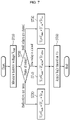
- FIG. 7 is a flowchart showing a method of correcting a measured voltage according to yet another embodiment.
- a processor (210 in FIG. 2 ) of a battery management system measures a voltage of a battery (21 in FIG. 2 ) at S710. Further, the processor 210 checks current states of relays (220 and 230 in FIG. 2 ) at S720. Steps S710 and S720 may be performed simultaneously, or either one of the two steps may be performed first.
- the processor 210 corrects the measures battery voltage V BMS based on a forward voltage drop of a diode (D1 in FIG. 2 ) and a voltage drop across a wire (23 in FIG. 2 ) in a state in which both the relays 220 and 230 are open, and outputs the corrected battery voltage Vs at S730.
- the processor 210 may correct the measured battery voltage V BMS by adding to the measured battery voltage V BMS a correction value Vfoff according to the forward voltage drop of the diode D1 and a correction value Vr off according to the voltage drop across the wire 23 in a state in which both the relays 220 and 230 are open.
- the processor 210 corrects the measures battery voltage V BMS based on a forward voltage drop of the diode D1 and a voltage drop across the wire 23 in a state in which one of the relays 220 and 230 are open, and outputs the corrected battery voltage Vs at S740.
- the processor 210 may correct the measured battery voltage V BMS by adding to the measured battery voltage V BMS a correction value Vf off/on according to the forward voltage drop of the diode D1 and a correction value Vr off/on according to the voltage drop across the wire 23 in a state in which one of the relays 220 and 230 are open.
- the processor 210 corrects the measured battery voltage V BMS based on a forward voltage drop of the diode D1 and a voltage drop across the wire 23 in a state in which both the relays 220 and 230 are closed, and outputs the corrected battery voltage Vs at S750.
- the processor 210 may correct the measured battery voltage V BMS by adding to the measured battery voltage V BMS a correction value Vf on according to the forward voltage drop of the diode D1 and a correction value Vr on according to the voltage drop across the wire 23 in a state in which both the relays 220 and 230 are closed.
- Vs ⁇ V BMS + Vf off + Vr off if two relays are open V BMS + Vf off/on + Vr off/on if one relay is open V BMS + Vf on + Vr on if two relays are closed
- the processor 210 may apply logic according to a command from a processor of a vehicle based on the corrected battery voltage Vs. In one embodiment, the processor 210 may determine whether to control the relays 220 and 230 based on the corrected battery voltage Vs at S760.
- the voltage of the battery 21 measured by the processor 210 can be corrected based on the forward voltage drop of the diode D1 and the voltage drop across the wire 23 so that the error between the voltages measured by the two processors 24 and 210 can be reduced. Accordingly, it is possible to prevent the two processors 24 and 210 to which the same logic is applied from performing different operations.
Landscapes
- Engineering & Computer Science (AREA)
- General Physics & Mathematics (AREA)
- Physics & Mathematics (AREA)
- Theoretical Computer Science (AREA)
- Power Engineering (AREA)
- General Chemical & Material Sciences (AREA)
- Electrochemistry (AREA)
- Chemical Kinetics & Catalysis (AREA)
- General Engineering & Computer Science (AREA)
- Chemical & Material Sciences (AREA)
- Manufacturing & Machinery (AREA)
- Microelectronics & Electronic Packaging (AREA)
- Secondary Cells (AREA)
- Charge And Discharge Circuits For Batteries Or The Like (AREA)
- Measurement Of Current Or Voltage (AREA)
Abstract
Description
- This application claims priority to and the benefit of
Korean Patent Application No. 10-2020-0089445 filed in the Korean Intellectual Property Office on July 20, 2020 - The described technology relates to a battery apparatus, a battery management system, and a method for correcting measured voltage.
- An electric vehicle or a hybrid vehicle is a vehicle that obtains power by driving a motor mainly using a battery as a power supply. The electric vehicles are being actively researched because they are alternatives that can solve pollution and energy problems of internal combustion vehicles. Rechargeable batteries are used in various external apparatuses other than the electric vehicles.
- In addition to the battery for driving the motor, a battery is also used as a power supply for supplying a voltage (e.g., 12V) to various processors. The vehicle's processor communicates with other processors to check a status of a control device and instruct an operation by using such a power supply. Further, the vehicle's processor transmits an on/off command of a contactor such as a relay used in the battery, and a processor of a battery management system controls an on/off operation of the relay according to the command from the vehicle's processor.
- An amount of current may increase according to the on/off operation of the relay. A voltage of the power supply measured by the processor of the battery management system may be different from a voltage of the power supply measured by the vehicle's processor due to a voltage drop caused by the current. Accordingly, even if the same logic is applied to both processors, a situation in which the same operation cannot be performed may occur.
- Some embodiments may provide a battery apparatus, a battery management system, and a method for correcting a measured voltage, capable of correcting a voltage measured by a processor of the battery management system.
- According to an embodiment, a battery apparatus including a battery pack and a battery management system connected to the battery pack is provided. The battery management system may include a circuit to which a voltage from a power supply is supplied and configured to be used to manage the battery pack, and a processor configured to measure a voltage supplied from the power supply and correct the measured voltage based on a voltage drop occurred in the circuit.
- In some embodiments, the voltage drop may include a voltage drop across a wire connecting the power supply and the circuit.
- In some embodiments, the circuit may include a diode having an anode connected to a wire connecting the power supply and the circuit and configured to transfer the voltage from the power supply to the circuit through a cathode. The voltage drop may include a forward voltage drop of the diode.
- In some embodiments, the voltage drop may further include a voltage drop across the wire.
- In some embodiments, the processor may determine control of the circuit based on the corrected voltage.
- In some embodiments, the processor may communicate with a processor of an external apparatus to which the battery apparatus is connected, and may receive a command from the processor of the external apparatus to control the circuit.
- In some embodiments, the circuit may include a heating resistor configured to heat the battery pack, a first relay connected between a first terminal of the heating resistor and a positive terminal of the battery pack and configured to operate based on the voltage from the power supply, and a second relay connected between a second terminal of the heating resistor and a negative terminal of the battery pack and configured to operate based on the voltage from the power supply. The processor may control operations of the first relay and the second relay. A correction value for correcting the measured voltage based on the voltage drop may be vary depending on states of the first relay and the second relay.
- In some embodiments, the correction value of a state in which the first relay and the second relay are closed may be greater than the correction value of a state in which one of the first relay and the second relay is closed and the other is open. The correction value of a state in which one of the first relay and the second relay is closed and the other is opened may be greater than the correction value of a state in which the first relay and the second relay are open.
- In some embodiments, the processor may correct the measured voltage by adding the correction value to the measured voltage.
- In some embodiments, the first relay may include a first switch connected between the first terminal of the heating resistor and the positive terminal of the battery pack and a first relay coil configured to drive the first switch. The second relay may include a second switch connected between the second terminal of the heating resistor and the negative terminal of the battery pack and a second relay coil configured to drive the second switch. The circuit may further include a first driver connected to the first relay coil and a second driver connected to the second relay coil. The processor may control the first driver to supply the voltage from the power supply to the first relay coil, and control the second driver to supply the voltage from the power supply to the second relay coil.
- According to another embodiment, a method of, by a processor, measuring and correcting a voltage of a power supply used in a circuit configured to manage a battery pack is provided. The method includes measuring the voltage of the power supply, determining a state of the circuit, determining a correction value based on the state of the circuit, and correcting the measured voltage based on the correction value.
- In some embodiments, the method may further include determining control of the circuit based on the corrected voltage.
- In some embodiments, determining the correction value may include determining the correction value based on a voltage drop according to the state of the circuit.
- In some embodiments, the state of the circuit may include states of a plurality of relays included in the circuit.
- According to yet another embodiment, a battery management system connected to a battery pack is provided. The battery management system includes a circuit to which a voltage from a power supply is supplied and configured to be used to manage the battery pack, and a processor configured to control the circuit, measure a voltage supplied from the power supply, and correct the measured voltage based on a voltage drop occurred in the circuit.
- According to an embodiment, even if a voltage drop occurs in a circuit of the battery management system according to a status of relays, a voltage measured by a processor may be corrected based on the voltage drop.
-
-
FIG. 1 is a drawing showing a battery apparatus according to an embodiment. -
FIG. 2 is a diagram for explaining a battery management system according to an embodiment. -
FIG. 3 is a diagram showing a forward voltage of a diode according to a status of a relay. -
FIG. 4 is a diagram showing a voltage drop across a wire according to a status of a relay. -
FIG. 5 is a flowchart showing a method for correcting a measured voltage according to an embodiment. -
FIG. 6 is a flowchart showing a method of correcting a measured voltage according to another embodiment. -
FIG. 7 is a flowchart showing a method of correcting a measured voltage according to yet another embodiment. - In the following detailed description, only certain embodiments have been shown and described, simply by way of illustration. As those skilled in the art would realize, the described embodiments may be modified in various different ways, all without departing from the spirit or scope of the present invention. Accordingly, the drawings and description are to be regarded as illustrative in nature and not restrictive. Like reference numerals designate like elements throughout the specification.
- When it is described that an element is "connected" to another element, it should be understood that the element may be directly connected to the other element or connected to the other element through a third element. On the other hand, when it is described that an element is "directly connected" to another element, it should be understood that the element is connected to the other element through no third element.
- As used herein, a singular form may be intended to include a plural form as well, unless the explicit expression such as "one" or "single" is used.
- In flowcharts described with reference to the drawings, the order of operations or steps may be changed, several operations or steps may be merged, a certain operation or step may be divided, and a specific operation or step may not be performed.
-
FIG. 1 is a drawing showing a battery apparatus according to an embodiment. - Referring to
FIG. 1 , abattery apparatus 100 has a structure that can be electrically connected to anexternal apparatus 10 through a positive link terminal DC(+) and a negative link terminal DC(-). When the external apparatus is a load, thebattery apparatus 100 is discharged by operating as a power supply that supplies power to the load. Theexternal apparatus 10 operating as the load may be, for example, an electronic device, a mobility apparatus, or an energy storage system (ESS). The mobility apparatus may be, for example, a vehicle such as an electric vehicle, a hybrid vehicle, or a smart mobility. - The
battery apparatus 100 includes abattery pack 110,switches - The
battery pack 110 includes a plurality of battery cells (not shown), and has a positive terminal PV(+) and a negative terminal PV(-). In some embodiments, the battery cell may be a rechargeable cell. In one embodiment, in thebattery pack 110, a predetermined number of battery cells are connected in series to configure a battery module to supply desired power. In another embodiment, in thebattery pack 110, a predetermined number of battery modules may be connected in series or in parallel to supply desired power. - The
switch 121 is connected between the positive terminal PV(+) of thebattery pack 110 and the positive link terminal DC(+) of thebattery apparatus 100. Theswitch 122 is connected between the negative terminal PV(-) of thebattery pack 110 and the negative link terminal DC(-) of thebattery apparatus 100. Theswitches battery management system 130 to control an electrical connection between thebattery pack 110 and theexternal apparatus 10. In some embodiments, each of theswitches battery apparatus 100 may further include driving circuits (not shown) for controlling theswitches - The
battery management system 130 may include various monitoring circuits (not shown) and the processor (not shown). Various sensing circuits may monitor a voltage, a temperature, a current, and the like of thebattery pack 110. The processor may determine a state of thebattery pack 110 based on information monitored by various monitoring circuits. The processor may be, for example, a micro controller unit (MCU). Thebattery management system 130 may further include a heating device (not shown) for controlling the temperature of thebattery pack 110, and the processor may control an operation of the heating device. - The
battery apparatus 100 or theexternal apparatus 10 may further include a battery as a power supply that supplies a voltage for operating thebattery management system 130. The power supply may also supply a voltage to theexternal apparatus 10, for example a processor in a vehicle. In this case, a voltage drop occurs in thebattery management system 130 by an operation of a heating device so that an error may occur between the voltage of the power supply measured by the processor of thebattery management system 130 and the voltage of the power supply measured by the processor of the vehicle. Hereinafter, embodiments for correcting such an error are described. -
FIG. 2 is a diagram for explaining a battery management system according to an embodiment. - Referring to
FIG. 2 , apower supply 21 supplies a voltage Vs to aprocessor 24 of anexternal apparatus 20, for example, a vehicle, through awire 22, and supplies the voltage Vs to abattery management system 200 through awire 23. In some embodiments, thepower supply 21 may include a battery. Thebattery 21 may supply, for example, a voltage of 12V. In some embodiments, thebattery 21 may be a lead acid battery or a lithium ion battery. - The
processor 24 of the vehicle communicates with other processors of the vehicle and issues commands for turning on/off various devices. Further, theprocessor 24 measures the voltage Vs supplied from thebattery 21. To this end, the vehicle may further include a voltage sensing circuit. In some embodiments, the voltage sensing circuit may include two resistors R11 and R12 connected in series between thewire 22 and a ground terminal. The voltage Vs may be divided by the two resistors R11 and R12, and the divided voltage may be transferred to theprocessor 24. In one embodiment, the voltage sensing circuit may further include an analog-to-digital converter for converting the divided voltage into a digital signal. Theprocessor 24 may check the voltage Vs of thebattery 21 detected by the voltage detection circuit. - The
battery management system 200 is connected to abattery pack 25, and includes aprocessor 210 and a management circuit used to manage thebattery pack 25. Theprocessor 210 measures the voltage Vs supplied from thebattery 21. To this end, the management circuit may further include a voltage sensing circuit. In some embodiments, the voltage sensing circuit may include two resistors R21 and R22 connected in series between thewire 23 and the ground terminal. The voltage Vs may be divided by the two resistors R21 and R22, and the divided voltage may be transferred to theprocessor 210. In one embodiment, the voltage sensing circuit may further include an analog-to-digital converter for converting the divided voltage into a digital signal. Theprocessor 210 may check the voltage Vs of thebattery 21 detected by the voltage detection circuit. - In some embodiments, the
processor 210 may communicate with the vehicle'sprocessor 24 to transfer information of thebattery pack 25. The information of thebattery pack 25 may include a cell voltage of thebattery pack 25 and a temperature of thebattery pack 25. Theprocessor 24 of the vehicle may send a command to theprocessor 210 based on the information of thebattery pack 25. In one embodiment, a controller area network (CAN) communication may be used for communication between theprocessor 210 and theprocessor 24. - In some embodiments, the management circuit may include a heating device. The heating device is a device for heating the
battery pack 25, and includes a heating resistor Rh, relays 220 and 230, anddrivers battery pack 25, thereby increasing the temperature. Therelay 220 includes arelay switch 221 and arelay coil 222 for driving therelay switch 221, and therelay 230 includes arelay switch 231 and arelay coil 232 for driving therelay switch 231. Therelay switch 221 is connected between a positive terminal PV(+) of thebattery pack 25 and a first terminal of the heating resistor Rh, and therelay switch 231 is connected between a negative terminal of thebattery pack 25 and a second terminal of the heating resistor Rh. When the relay switches 221 and 231 are turned on, current flows from thebattery pack 25 to the heating resistor Rh so that thebattery pack 25 can be heated. A first terminal of thedriver 240 receives the voltage Vs from thewire 23, the second terminal of thedriver 240 is connected to a first terminal of therelay coil 222, and a second terminal of therelay coil 222 is connected to the ground terminal. A first terminal of thedriver 250 receives the voltage Vs from thewire 23, a second terminal of thedriver 250 is connected to a first terminal of therelay coil 232, and a second terminal of therelay coil 232 is connected to the ground terminal. - The
drivers wire 23 to the relay coils 222 and 232 in response to enable signals from theprocessor 210, respectively. Accordingly, current flows in the relay coils 222 and 232 so that the relay switches 221 and 231 can be turned on by the relay coils 222 and 232, respectively. Each of thedrivers processor 210. In some embodiments, theprocessor 24 of the vehicle may receive the temperature of thebattery pack 25 from theprocessor 210 and transfer to the processor 210 a command to close therelays battery pack 25 is lower than a reference temperature. Theprocessor 210 may transfer the enable signals to thedrivers processor 24. Closing the relay may be referred to as ON of the relay, and opening the relay may be referred to as OFF of the relay. - In some embodiments, one of the
relays relay 230 is removed, the second terminal of the heating resistor Rh is connected to the ground terminal, and the current flowing through the heating resistor Rh may be controlled by therelay 220. - In some embodiments, the
battery management system 200 may further include a diode D1 to protect thebattery 21 from a reverse voltage to be generated by the relay coils 222 and 232. In this case, an anode of the diode D1 may be connected to thewire 23, and the voltage Vs may be transferred to therelays - In some embodiments, a DC/
DC converter 260 may be further included to supply the fixed voltage Vs to the relay coils 222 and 232. An input terminal of the DC/DC converter 260 may be connected to the cathode of the diode D1, and the fixed voltage Vs may be transferred to therelays DC converter 260. - In this case, an error may occur between the voltage of the
battery 21 measured by theprocessor 24 of the vehicle and the voltage of thebattery 21 measured by theprocessor 210 of thebattery management system 200. For example, when the voltage Vs of thebattery 21 is measured to be a normal voltage of 12V as a result of measuring the voltage Vs of thebattery 21 by theprocessor 24 of the vehicle, theprocessor 24 may transfer to theprocessor 210 of the battery management system 200 a command to close therelays processor 210 may measure the voltage of thebattery 21 and then output a signal to close therelay 220 if the measurement result is 12V. After outputting the signal to close therelay 220 and before outputting the signal to close therelay 230, theprocessor 210 may measure the voltage of thebattery 21 again. In this case, thedriver 240 is turned on to close therelay 220 so that the current flowing in therelay coil 222 may increase. Because of a voltage drop across thewire 23 and an increase in a forward voltage of the diode D1 by the current flowing in therelay coil 222, the voltage Vs of thebattery 21 measured by theprocessor 210 may be 10V lower than 12V. Then, theprocessor 210 may determine that it is difficult to supply sufficient power to close therelay 230 with 10V and then not close therelay 230. - In this way, although the
processor 24 of the vehicle may accurately measure the voltage of thebattery 21 because the voltage drop hardly occurs in thewire 22, the voltage of thebattery 21 measured by theprocessor 210 of thebattery management system 200 may be lower than the actual voltage because of the voltage drop across in thewire 23 and the forward voltage of the diode D1. As a result, the error may occur between the voltage measurements of thebattery 21 by the twoprocessors processors -
FIG. 3 is a diagram showing a forward voltage of a diode according to a status of a relay, andFIG. 4 is a diagram showing a voltage drop across a wire according to a status of a relay. - Referring to
FIG. 3 , the smallest current Id flows through a diode (D1 inFIG. 2 ) when both relays (220 and 230 inFIG. 2 ) are open, and the greatest current Id flows through the diode D1 when both therelays relays relays relays relays relays - Referring to
FIG. 4 , the smallest current Id flows in the wire (23 inFIG. 2 ) when both relays (220 and 230 inFIG. 2 ) are open, and the greatest current Id flows in thewire 23 when both therelays relays relays relays wire 23 due to a resistance of thewire 23 also increases. As a result, the voltage drop Vr is also the smallest when both therelays relays relays - Next, a method for correcting a measured voltage according to various embodiments is described with reference to
FIG. 5 to FIG. 7 . -
FIG. 5 is a flowchart showing a method for correcting a measured voltage according to an embodiment. - Referring to
FIG. 5 , a processor (210 inFIG. 2 ) of a battery management system measures a voltage of a battery (21 inFIG. 2 ) at S510. Further, theprocessor 210 checks current states of relays (220 or 230 inFIG. 2 ) at S520. Steps S510 and S520 may be performed simultaneously, or either one of the two steps may be performed first. - When both the
relays processor 210 corrects the measured battery voltage VBMS based on a forward voltage drop of a diode (D1 inFIG. 2 ) in a state in which both therelays processor 210 may correct the measured battery voltage VBMS by adding to the measured battery voltage VBMS a correction value Vfoff according to the forward voltage drop of the diode D1 in a state in which both therelays - When one of the
relays processor 210 corrects the measured battery voltage VBMS based on a forward voltage drop of the diode D1 in a state in which one of therelays processor 210 may correct the measured battery voltage VBMS by adding to the measured battery voltage VBMS a correction value Vfoff/on according to the forward voltage drop of the diode D1 in a state in which one of therelays - When both the
relays processor 210 corrects the measured battery voltage VBMS based on a forward voltage drop of the diode D1 in a state in which both therelays processor 210 may correct the measured battery voltage VBMS by adding to the measured battery voltage VBMS a correction value Vfon according to the forward voltage drop of the diode D1 in a state in which both therelays - The corrected battery voltage Vs calculated at steps S530, S540, and S550 may be expressed as in below Equation 1.

- In some embodiments, at S560, the
processor 210 may apply logic according to a command from a processor of a vehicle based on the corrected battery voltage Vs. In one embodiment, theprocessor 210 may determine whether to control therelays - In some embodiments, when a product of the
relay 220 is different from a product of therelay 230, the correction value according to the forward voltage drop of the diode D1 in a state in which therelay 220 is opened and therelay 230 is closed may be different from the correction value according to the forward voltage drop of the diode D1 in a state in which therelay 220 is closed and therelay 230 is opened. - In some embodiments, the correction value according to the forward voltage drop of the diode D1 based on the states of the relays may be calculated after measuring the forward voltage of the diode D1 according to the states of the relays as shown in
FIG. 3 . In one embodiment, the correction value according to the forward voltage drop of the diode D1 may have been stored in theprocessor 210 or a storage device accessible by theprocessor 210. - According to the above-described embodiments, even if the forward voltage drop of the diode D1 occurs according to the states of the
relays battery 21 measured by theprocessor 210 can be corrected based on the forward voltage drop of the diode D1 so that the error between the voltages measured by the twoprocessors processors -
FIG. 6 is a flowchart showing a method of correcting a measured voltage according to another embodiment. - Referring to
FIG. 6 , a processor (210 inFIG. 2 ) of a battery management system measures a voltage of a battery (21 inFIG. 2 ) at S610. Further, theprocessor 210 checks current states of relays (220 and 230 inFIG. 2 ) at S620. Steps S610 and S620 may be performed simultaneously, or either one of the two steps may be performed first. - When both the
relays processor 210 corrects the measures battery voltage VBMS based on a voltage drop across a wire (23 inFIG. 2 ) in a state in which both therelays processor 210 may correct the measured battery voltage VBMS by adding to the measured battery voltage VBMS a correction value Vroff according to the voltage drop across thewire 23 in a state in which both therelays - When one of the
relays processor 210 corrects the measures battery voltage VBMS based on a voltage drop across thewire 23 in a state in which one of therelays processor 210 may correct the measured battery voltage VBMS by adding to the measured battery voltage VBMS a correction value Vroff/on according to the voltage drop across thewire 23 in a state in which one of therelays - When both the
relays processor 210 corrects the measured battery voltage VBMS based on a voltage drop across thewire 23 in a state in which both therelays processor 210 may correct the measured battery voltage VBMS by adding to the measured battery voltage VBMS a correction value Vron according to the voltage drop across thewire 23 in a state in which both therelays - The corrected battery voltage Vs calculated in steps S630, S640 and S650 may be expressed as in below Equation 2.

- In some embodiments, at S660, the
processor 210 may apply logic according to a command from a processor of a vehicle based on the corrected battery voltage Vs. In one embodiment, theprocessor 210 may determine whether to control therelays - In some embodiments, when a product of the
relay 220 is different from a product of therelay 230, the correction value according to the voltage drop across thewire 23 in a state in which therelay 220 is opened and therelay 230 is closed may be different from the correction value according to the voltage drop across thewire 23 in a state in which therelay 220 is closed and therelay 230 is opened. - In some embodiments, the correction value according to the voltage drop across the
wire 23 based on the states of the relays may be calculated after measuring the voltage drop across thewire 23 according to the states of the relays as shown inFIG. 4 . In one embodiment, the correction value according to the voltage drop across thewire 23 may have been stored in theprocessor 210 or a storage device accessible by theprocessor 210. - According to the above-described embodiments, even if the voltage drop across the
wire 23 occurs according to the states of therelays battery 21 measured by theprocessor 210 can be corrected based on the voltage drop across thewire 23 so that the error between the voltages measured by the twoprocessors processors -
FIG. 7 is a flowchart showing a method of correcting a measured voltage according to yet another embodiment. - Referring to
FIG. 6 , a processor (210 inFIG. 2 ) of a battery management system measures a voltage of a battery (21 inFIG. 2 ) at S710. Further, theprocessor 210 checks current states of relays (220 and 230 inFIG. 2 ) at S720. Steps S710 and S720 may be performed simultaneously, or either one of the two steps may be performed first. - When both the
relays processor 210 corrects the measures battery voltage VBMS based on a forward voltage drop of a diode (D1 inFIG. 2 ) and a voltage drop across a wire (23 inFIG. 2 ) in a state in which both therelays processor 210 may correct the measured battery voltage VBMS by adding to the measured battery voltage VBMS a correction value Vfoff according to the forward voltage drop of the diode D1 and a correction value Vroff according to the voltage drop across thewire 23 in a state in which both therelays - When one of the
relays processor 210 corrects the measures battery voltage VBMS based on a forward voltage drop of the diode D1 and a voltage drop across thewire 23 in a state in which one of therelays processor 210 may correct the measured battery voltage VBMS by adding to the measured battery voltage VBMS a correction value Vfoff/on according to the forward voltage drop of the diode D1 and a correction value Vroff/on according to the voltage drop across thewire 23 in a state in which one of therelays - When both the
relays processor 210 corrects the measured battery voltage VBMS based on a forward voltage drop of the diode D1 and a voltage drop across thewire 23 in a state in which both therelays processor 210 may correct the measured battery voltage VBMS by adding to the measured battery voltage VBMS a correction value Vfon according to the forward voltage drop of the diode D1 and a correction value Vron according to the voltage drop across thewire 23 in a state in which both therelays - The corrected battery voltage Vs calculated in steps S730, S740 and S750 may be expressed as in below Equation 3.

- In some embodiments, at S760, the
processor 210 may apply logic according to a command from a processor of a vehicle based on the corrected battery voltage Vs. In one embodiment, theprocessor 210 may determine whether to control therelays - According to the above-described embodiments, even if the forward voltage drop of the diode D1 and the voltage drop across the
wire 23 occurs according to the states of therelays battery 21 measured by theprocessor 210 can be corrected based on the forward voltage drop of the diode D1 and the voltage drop across thewire 23 so that the error between the voltages measured by the twoprocessors processors - While this invention has been described in connection with what is presently considered to be practical embodiments, it is to be understood that the invention is not limited to the disclosed embodiments. On the contrary, it is intended to cover various modifications and equivalent arrangements included within the spirit and scope of the appended claims.
Claims (20)
- A battery apparatus comprising:a battery pack; anda battery management system connected to the battery pack,wherein the battery management system includes:a circuit to which a voltage from a power supply is supplied and configured to be used to manage the battery pack; anda processor configured to measure a voltage supplied from the power supply and correct the measured voltage based on a voltage drop occurred in the circuit.
- The battery apparatus of claim 1, wherein the voltage drop includes a voltage drop across a wire connecting the power supply and the circuit.
- The battery apparatus of claim 1, wherein the circuit includes a diode having an anode connected to a wire connecting the power supply and the circuit and configured to transfer the voltage from the power supply to the circuit through a cathode, and
wherein the voltage drop includes a forward voltage drop of the diode. - The battery apparatus of claim 3, wherein the voltage drop further includes a voltage drop across the wire.
- The battery apparatus of claim 1, wherein the processor is configured to determine control of the circuit based on the corrected voltage.
- The battery apparatus of claim 1, wherein the processor is configured to communicate with a processor of an external apparatus to which the battery apparatus is connected, and receive a command from the processor of the external apparatus to control the circuit.
- The battery apparatus of claim 1, wherein the circuit includes:a heating resistor configured to heat the battery pack;a first relay connected between a first terminal of the heating resistor and a positive terminal of the battery pack and configured to operate based on the voltage from the power supply; anda second relay connected between a second terminal of the heating resistor and a negative terminal of the battery pack and configured to operate based on the voltage from the power supply,wherein the processor is configured to control operations of the first relay and the second relay, andwherein a correction value for correcting the measured voltage based on the voltage drop varies depending on states of the first relay and the second relay.
- The battery apparatus of claim 7, wherein the correction value of a state in which the first relay and the second relay are closed is greater than the correction value of a state in which one of the first relay and the second relay is closed and the other is open, and
wherein the correction value of a state in which one of the first relay and the second relay is closed and the other is opened is greater than the correction value of a state in which the first relay and the second relay are open. - The battery apparatus of claim 7, wherein the processor is configured to correct the measured voltage by adding the correction value to the measured voltage.
- The battery apparatus of claim 7, wherein the first relay includes a first switch connected between the first terminal of the heating resistor and the positive terminal of the battery pack and a first relay coil configured to drive the first switch,wherein the second relay includes a second switch connected between the second terminal of the heating resistor and the negative terminal of the battery pack and a second relay coil configured to drive the second switch,wherein the circuit further includes a first driver connected to the first relay coil and a second driver connected to the second relay coil, andwherein the processor is configured to control the first driver to supply the voltage from the power supply to the first relay coil, and control the second driver to supply the voltage from the power supply to the second relay coil.
- A method of, by a processor, measuring and correcting a voltage of a power supply used in a circuit configured to manage a battery pack, the method comprising:measuring the voltage of the power supply;determining a state of the circuit;determining a correction value based on the state of the circuit; andcorrecting the measured voltage based on the correction value.
- The method of claim 11, further comprising determining control of the circuit based on the corrected voltage.
- The method of claim 11, wherein determining the correction value includes determining the correction value based on a voltage drop according to the state of the circuit.
- The method of claim 13, wherein the state of the circuit includes states of a plurality of relays included in the circuit.
- The method of claim 13, wherein the voltage drop includes a voltage drop across a wire connecting the power supply and the circuit.
- The method of claim 13, wherein the voltage drop includes a forward voltage drop of a diode having an anode connected to the power supply and configured to transfer the voltage from the power supply to the circuit through a cathode.
- A battery management system connected to a battery pack, comprising:a circuit to which a voltage from a power supply is supplied and configured to be used to manage the battery pack; anda processor configured to control the circuit, measure a voltage supplied from the power supply, and correct the measured voltage based on a voltage drop occurred in the circuit.
- The battery management system of claim 17, wherein the circuit includes a diode having an anode connected to a wire connecting the power supply and the circuit and configured to transfer the voltage from the power supply to the circuit through a cathode, and
wherein the voltage drop includes a forward voltage drop of the diode. - The battery management system of claim 17, wherein the voltage drop includes a voltage drop across a wire connecting the power supply and the circuit.
- The battery management system of claim 17, wherein the circuit includes a plurality of relays, and
wherein a correction value determined based on the voltage drop varies depending on states of the first relay and the second relay.
Applications Claiming Priority (2)
| Application Number | Priority Date | Filing Date | Title |
|---|---|---|---|
| KR1020200089445A KR20220010842A (en) | 2020-07-20 | 2020-07-20 | Battery apparatus, battery management system, and method for correcting measured voltage |
| PCT/KR2021/008323 WO2022019516A1 (en) | 2020-07-20 | 2021-07-01 | Battery apparatus, battery management system, and method for correcting measured voltage |
Publications (3)
| Publication Number | Publication Date |
|---|---|
| EP3989388A1 true EP3989388A1 (en) | 2022-04-27 |
| EP3989388A4 EP3989388A4 (en) | 2022-11-09 |
| EP3989388B1 EP3989388B1 (en) | 2026-01-07 |
Family
ID=79729275
Family Applications (1)
| Application Number | Title | Priority Date | Filing Date |
|---|---|---|---|
| EP21840767.4A Active EP3989388B1 (en) | 2020-07-20 | 2021-07-01 | Battery apparatus, battery management system, and method for correcting measured voltage |
Country Status (7)
| Country | Link |
|---|---|
| US (1) | US12026030B2 (en) |
| EP (1) | EP3989388B1 (en) |
| JP (1) | JP7368059B2 (en) |
| KR (1) | KR20220010842A (en) |
| CN (1) | CN114258496B (en) |
| ES (1) | ES3060432T3 (en) |
| WO (1) | WO2022019516A1 (en) |
Families Citing this family (2)
| Publication number | Priority date | Publication date | Assignee | Title |
|---|---|---|---|---|
| CN115616463B (en) * | 2022-10-08 | 2026-01-06 | 阳光储能技术有限公司 | Calibration methods and devices for energy storage systems and their current and voltage detection functions |
| KR20240141545A (en) * | 2023-03-20 | 2024-09-27 | 삼성에스디아이 주식회사 | High-side driver diagnosis method and battery system |
Family Cites Families (34)
| Publication number | Priority date | Publication date | Assignee | Title |
|---|---|---|---|---|
| JPH1070846A (en) | 1996-08-27 | 1998-03-10 | Matsushita Electric Ind Co Ltd | Charging device |
| US5957374A (en) * | 1998-03-17 | 1999-09-28 | Hunter Fan Company | Voltage boosting system and method for electronic thermostat relay |
| US6515456B1 (en) * | 2000-04-13 | 2003-02-04 | Mixon, Inc. | Battery charger apparatus |
| KR100390362B1 (en) * | 2000-09-26 | 2003-07-07 | 엘지전자 주식회사 | Control method for battery charging of mobile phone having charger |
| US6479968B1 (en) * | 2000-09-27 | 2002-11-12 | Motorola, Inc. | Method of charging a battery utilizing dynamic cable compensation |
| KR100471236B1 (en) | 2002-06-29 | 2005-03-10 | 현대자동차주식회사 | Assistance battery voltage compensation apparatus of electric vehicle |
| JP2004166370A (en) | 2002-11-12 | 2004-06-10 | Toyota Motor Corp | Voltage converter |
| US6936995B2 (en) * | 2003-02-25 | 2005-08-30 | General Motors Corporation | Battery voltage reduction |
| EP1873886B1 (en) | 2006-06-30 | 2012-10-24 | Datalogic IP TECH S.r.l. | Method and apparatus for charging batteries |
| KR100908716B1 (en) * | 2007-03-02 | 2009-07-22 | 삼성에스디아이 주식회사 | Battery Management System and Its Driving Method |
| JP2009250796A (en) * | 2008-04-07 | 2009-10-29 | Mitsubishi Electric Corp | Method of diagnosing deterioration of storage battery and diagnostic system |
| JP2010213499A (en) | 2009-03-11 | 2010-09-24 | Omron Corp | Charge controller and method, charger, and program |
| JP5436364B2 (en) | 2010-08-09 | 2014-03-05 | オムロンオートモーティブエレクトロニクス株式会社 | DCDC converter |
| JP5100804B2 (en) * | 2010-09-13 | 2012-12-19 | 三菱電機株式会社 | Start control unit and start command signal generator for the same |
| KR101146404B1 (en) * | 2010-12-20 | 2012-05-17 | 삼성에스디아이 주식회사 | Battery management system and battery pack comprising the same |
| JP5789846B2 (en) | 2011-09-05 | 2015-10-07 | 三洋電機株式会社 | Power supply device for vehicle and vehicle equipped with this power supply device |
| TWI627812B (en) | 2013-04-05 | 2018-06-21 | 美商線性科技股份有限公司 | Device, system and method for voltage compensation active battery balancing |
| CN103780096A (en) * | 2014-01-24 | 2014-05-07 | 上海新进半导体制造有限公司 | Switch power source, control chip and method for voltage compensation for charging cable |
| KR101551068B1 (en) * | 2014-03-14 | 2015-09-07 | 현대자동차주식회사 | Stable power supply device for high voltage battery system |
| JP2017009422A (en) | 2015-06-22 | 2017-01-12 | オリジン電気株式会社 | Storage battery diagnostic measuring apparatus and storage battery diagnostic measuring method |
| KR101700805B1 (en) * | 2014-09-04 | 2017-01-31 | 주식회사 엘지화학 | Battery system and electric storage system including the same |
| US9843069B2 (en) | 2014-09-26 | 2017-12-12 | Ford Global Technologies, Llc | Battery capacity degradation resolution methods and systems |
| KR101619420B1 (en) * | 2014-12-08 | 2016-05-10 | 현대오트론 주식회사 | Apparatus and method for protecting overcurrent of battery management system |
| CN205178581U (en) * | 2015-11-30 | 2016-04-20 | 河北大学 | Lithium ion power batteries management system |
| US10666070B2 (en) * | 2016-01-07 | 2020-05-26 | Fairchild Semiconductor Corporation | Battery charge termination voltage reduction |
| CN105699904A (en) | 2016-01-19 | 2016-06-22 | 北京华大信安科技有限公司 | Battery voltage detecting circuit and method |
| KR101856367B1 (en) * | 2016-10-17 | 2018-05-09 | 현대자동차주식회사 | System and method for measuring offset current of current sensor for sensing current of battery |
| JP2018129896A (en) * | 2017-02-06 | 2018-08-16 | ゴイク電池株式会社 | Battery Management Unit |
| JP2018148654A (en) | 2017-03-03 | 2018-09-20 | Tdk株式会社 | Charging apparatus |
| CN107526041A (en) * | 2017-08-29 | 2017-12-29 | 宁德时代新能源科技股份有限公司 | Battery detection circuit and battery management system |
| KR102476377B1 (en) | 2017-09-18 | 2022-12-12 | 현대자동차주식회사 | System and method for voltage drop compensation control of power supply device |
| KR102448292B1 (en) | 2017-09-21 | 2022-09-28 | 삼성에스디아이 주식회사 | battery pack diagnostic device |
| JP7056113B2 (en) * | 2017-12-08 | 2022-04-19 | 株式会社デンソー | Battery control device |
| JP6725577B2 (en) | 2018-04-09 | 2020-07-22 | 矢崎総業株式会社 | Ground fault detector |
-
2020
- 2020-07-20 KR KR1020200089445A patent/KR20220010842A/en active Pending
-
2021
- 2021-07-01 CN CN202180004732.6A patent/CN114258496B/en active Active
- 2021-07-01 JP JP2022506644A patent/JP7368059B2/en active Active
- 2021-07-01 EP EP21840767.4A patent/EP3989388B1/en active Active
- 2021-07-01 US US17/625,177 patent/US12026030B2/en active Active
- 2021-07-01 WO PCT/KR2021/008323 patent/WO2022019516A1/en not_active Ceased
- 2021-07-01 ES ES21840767T patent/ES3060432T3/en active Active
Also Published As
| Publication number | Publication date |
|---|---|
| EP3989388A4 (en) | 2022-11-09 |
| KR20220010842A (en) | 2022-01-27 |
| JP7368059B2 (en) | 2023-10-24 |
| CN114258496B (en) | 2024-04-05 |
| US20220365578A1 (en) | 2022-11-17 |
| EP3989388B1 (en) | 2026-01-07 |
| JP2022544753A (en) | 2022-10-21 |
| ES3060432T3 (en) | 2026-03-26 |
| WO2022019516A1 (en) | 2022-01-27 |
| CN114258496A (en) | 2022-03-29 |
| US12026030B2 (en) | 2024-07-02 |
Similar Documents
| Publication | Publication Date | Title |
|---|---|---|
| EP4067922B1 (en) | Battery apparatus, battery management system, and method for diagnosing connection status | |
| CN103765721B (en) | Battery system monitoring arrangement | |
| EP2632021A1 (en) | Battery system | |
| EP3907813B1 (en) | Temperature measuring apparatus, battery apparatus including the same and temperature measuring method | |
| EP3989388B1 (en) | Battery apparatus, battery management system, and method for correcting measured voltage | |
| US12584963B2 (en) | Stuck-closed diagnosis method and battery system using the same | |
| US20250149671A1 (en) | Battery Apparatus and Diagnosing Method of Heater | |
| US12007445B2 (en) | Battery apparatus, battery management system, and method of diagnosing supply voltage of contactor | |
| EP4404426B1 (en) | Battery device, battery management system, and precharge duration setting method | |
| EP4401272B1 (en) | Battery device, battery system and diagnosis method | |
| US12246615B2 (en) | Current sensors for battery cells of a vehicle battery system | |
| KR102839450B1 (en) | Battery apparatus and drift fault diagnosis method | |
| EP4102245B1 (en) | Battery apparatus and current sensor diagnosis method | |
| EP4700407A1 (en) | Battery management system, battery device, and method for diagnosing cell voltage measurement line | |
| CN121043641A (en) | Solar charging system | |
| KR20220167594A (en) | Battery apparatus and method of controlling contactor |
Legal Events
| Date | Code | Title | Description |
|---|---|---|---|
| STAA | Information on the status of an ep patent application or granted ep patent |
Free format text: STATUS: UNKNOWN |
|
| STAA | Information on the status of an ep patent application or granted ep patent |
Free format text: STATUS: THE INTERNATIONAL PUBLICATION HAS BEEN MADE |
|
| PUAI | Public reference made under article 153(3) epc to a published international application that has entered the european phase |
Free format text: ORIGINAL CODE: 0009012 |
|
| STAA | Information on the status of an ep patent application or granted ep patent |
Free format text: STATUS: REQUEST FOR EXAMINATION WAS MADE |
|
| 17P | Request for examination filed |
Effective date: 20220121 |
|
| AK | Designated contracting states |
Kind code of ref document: A1 Designated state(s): AL AT BE BG CH CY CZ DE DK EE ES FI FR GB GR HR HU IE IS IT LI LT LU LV MC MK MT NL NO PL PT RO RS SE SI SK SM TR |
|
| REG | Reference to a national code |
Ref country code: DE Free format text: PREVIOUS MAIN CLASS: H02J0007000000 Ref country code: DE Ref legal event code: R079 Ref document number: 602021046105 Country of ref document: DE Free format text: PREVIOUS MAIN CLASS: H02J0007000000 Ipc: G01R0031383500 |
|
| A4 | Supplementary search report drawn up and despatched |
Effective date: 20221007 |
|
| RIC1 | Information provided on ipc code assigned before grant |
Ipc: G06F 1/3212 20190101ALI20220930BHEP Ipc: G06F 1/28 20060101ALI20220930BHEP Ipc: H02J 1/10 20060101ALI20220930BHEP Ipc: G06F 1/30 20060101ALI20220930BHEP Ipc: H01M 10/42 20060101ALI20220930BHEP Ipc: H02J 7/00 20060101ALI20220930BHEP Ipc: G01R 31/3835 20190101AFI20220930BHEP |
|
| DAV | Request for validation of the european patent (deleted) | ||
| DAX | Request for extension of the european patent (deleted) | ||
| GRAP | Despatch of communication of intention to grant a patent |
Free format text: ORIGINAL CODE: EPIDOSNIGR1 |
|
| STAA | Information on the status of an ep patent application or granted ep patent |
Free format text: STATUS: GRANT OF PATENT IS INTENDED |
|
| RIC1 | Information provided on ipc code assigned before grant |
Ipc: G01R 31/3835 20190101AFI20250710BHEP Ipc: H02J 7/00 20060101ALI20250710BHEP Ipc: H01M 10/42 20060101ALI20250710BHEP Ipc: H01M 10/48 20060101ALI20250710BHEP Ipc: H02J 1/10 20060101ALI20250710BHEP Ipc: G06F 1/28 20060101ALI20250710BHEP Ipc: G06F 1/3212 20190101ALI20250710BHEP |
|
| INTG | Intention to grant announced |
Effective date: 20250807 |
|
| P01 | Opt-out of the competence of the unified patent court (upc) registered |
Free format text: CASE NUMBER: UPC_APP_6725_3989388/2025 Effective date: 20250911 |
|
| GRAS | Grant fee paid |
Free format text: ORIGINAL CODE: EPIDOSNIGR3 |
|
| GRAA | (expected) grant |
Free format text: ORIGINAL CODE: 0009210 |
|
| STAA | Information on the status of an ep patent application or granted ep patent |
Free format text: STATUS: THE PATENT HAS BEEN GRANTED |
|
| AK | Designated contracting states |
Kind code of ref document: B1 Designated state(s): AL AT BE BG CH CY CZ DE DK EE ES FI FR GB GR HR HU IE IS IT LI LT LU LV MC MK MT NL NO PL PT RO RS SE SI SK SM TR |
|
| REG | Reference to a national code |
Ref country code: CH Ref legal event code: F10 Free format text: ST27 STATUS EVENT CODE: U-0-0-F10-F00 (AS PROVIDED BY THE NATIONAL OFFICE) Effective date: 20260107 Ref country code: GB Ref legal event code: FG4D |
|
| REG | Reference to a national code |
Ref country code: DE Ref legal event code: R096 Ref document number: 602021046105 Country of ref document: DE |
|
| REG | Reference to a national code |
Ref country code: IE Ref legal event code: FG4D |
|
| REG | Reference to a national code |
Ref country code: ES Ref legal event code: FG2A Ref document number: 3060432 Country of ref document: ES Kind code of ref document: T3 Effective date: 20260326 |