EP3988959A2 - Vorrichtungspositionierung - Google Patents
Vorrichtungspositionierung Download PDFInfo
- Publication number
- EP3988959A2 EP3988959A2 EP21199800.0A EP21199800A EP3988959A2 EP 3988959 A2 EP3988959 A2 EP 3988959A2 EP 21199800 A EP21199800 A EP 21199800A EP 3988959 A2 EP3988959 A2 EP 3988959A2
- Authority
- EP
- European Patent Office
- Prior art keywords
- communication node
- user device
- uplink
- measurement report
- measurement data
- Prior art date
- Legal status (The legal status is an assumption and is not a legal conclusion. Google has not performed a legal analysis and makes no representation as to the accuracy of the status listed.)
- Granted
Links
Images


Classifications
-
- G—PHYSICS
- G01—MEASURING; TESTING
- G01S—RADIO DIRECTION-FINDING; RADIO NAVIGATION; DETERMINING DISTANCE OR VELOCITY BY USE OF RADIO WAVES; LOCATING OR PRESENCE-DETECTING BY USE OF THE REFLECTION OR RERADIATION OF RADIO WAVES; ANALOGOUS ARRANGEMENTS USING OTHER WAVES
- G01S5/00—Position-fixing by co-ordinating two or more direction or position line determinations; Position-fixing by co-ordinating two or more distance determinations
- G01S5/0009—Transmission of position information to remote stations
-
- G—PHYSICS
- G01—MEASURING; TESTING
- G01S—RADIO DIRECTION-FINDING; RADIO NAVIGATION; DETERMINING DISTANCE OR VELOCITY BY USE OF RADIO WAVES; LOCATING OR PRESENCE-DETECTING BY USE OF THE REFLECTION OR RERADIATION OF RADIO WAVES; ANALOGOUS ARRANGEMENTS USING OTHER WAVES
- G01S5/00—Position-fixing by co-ordinating two or more direction or position line determinations; Position-fixing by co-ordinating two or more distance determinations
- G01S5/02—Position-fixing by co-ordinating two or more direction or position line determinations; Position-fixing by co-ordinating two or more distance determinations using radio waves
- G01S5/0205—Details
- G01S5/0244—Accuracy or reliability of position solution or of measurements contributing thereto
-
- G—PHYSICS
- G01—MEASURING; TESTING
- G01S—RADIO DIRECTION-FINDING; RADIO NAVIGATION; DETERMINING DISTANCE OR VELOCITY BY USE OF RADIO WAVES; LOCATING OR PRESENCE-DETECTING BY USE OF THE REFLECTION OR RERADIATION OF RADIO WAVES; ANALOGOUS ARRANGEMENTS USING OTHER WAVES
- G01S5/00—Position-fixing by co-ordinating two or more direction or position line determinations; Position-fixing by co-ordinating two or more distance determinations
- G01S5/0009—Transmission of position information to remote stations
- G01S5/0018—Transmission from mobile station to base station
- G01S5/0036—Transmission from mobile station to base station of measured values, i.e. measurement on mobile and position calculation on base station
-
- G—PHYSICS
- G01—MEASURING; TESTING
- G01S—RADIO DIRECTION-FINDING; RADIO NAVIGATION; DETERMINING DISTANCE OR VELOCITY BY USE OF RADIO WAVES; LOCATING OR PRESENCE-DETECTING BY USE OF THE REFLECTION OR RERADIATION OF RADIO WAVES; ANALOGOUS ARRANGEMENTS USING OTHER WAVES
- G01S5/00—Position-fixing by co-ordinating two or more direction or position line determinations; Position-fixing by co-ordinating two or more distance determinations
- G01S5/02—Position-fixing by co-ordinating two or more direction or position line determinations; Position-fixing by co-ordinating two or more distance determinations using radio waves
- G01S5/0205—Details
- G01S5/0221—Receivers
- G01S5/02213—Receivers arranged in a network for determining the position of a transmitter
- G01S5/02216—Timing or synchronisation of the receivers
-
- G—PHYSICS
- G01—MEASURING; TESTING
- G01S—RADIO DIRECTION-FINDING; RADIO NAVIGATION; DETERMINING DISTANCE OR VELOCITY BY USE OF RADIO WAVES; LOCATING OR PRESENCE-DETECTING BY USE OF THE REFLECTION OR RERADIATION OF RADIO WAVES; ANALOGOUS ARRANGEMENTS USING OTHER WAVES
- G01S5/00—Position-fixing by co-ordinating two or more direction or position line determinations; Position-fixing by co-ordinating two or more distance determinations
- G01S5/02—Position-fixing by co-ordinating two or more direction or position line determinations; Position-fixing by co-ordinating two or more distance determinations using radio waves
- G01S5/0257—Hybrid positioning
- G01S5/0268—Hybrid positioning by deriving positions from different combinations of signals or of estimated positions in a single positioning system
- G01S5/02685—Hybrid positioning by deriving positions from different combinations of signals or of estimated positions in a single positioning system involving dead reckoning based on radio wave measurements
-
- G—PHYSICS
- G01—MEASURING; TESTING
- G01S—RADIO DIRECTION-FINDING; RADIO NAVIGATION; DETERMINING DISTANCE OR VELOCITY BY USE OF RADIO WAVES; LOCATING OR PRESENCE-DETECTING BY USE OF THE REFLECTION OR RERADIATION OF RADIO WAVES; ANALOGOUS ARRANGEMENTS USING OTHER WAVES
- G01S5/00—Position-fixing by co-ordinating two or more direction or position line determinations; Position-fixing by co-ordinating two or more distance determinations
- G01S5/02—Position-fixing by co-ordinating two or more direction or position line determinations; Position-fixing by co-ordinating two or more distance determinations using radio waves
- G01S5/10—Position of receiver fixed by co-ordinating a plurality of position lines defined by path-difference measurements, e.g. omega or decca systems
-
- G—PHYSICS
- G01—MEASURING; TESTING
- G01S—RADIO DIRECTION-FINDING; RADIO NAVIGATION; DETERMINING DISTANCE OR VELOCITY BY USE OF RADIO WAVES; LOCATING OR PRESENCE-DETECTING BY USE OF THE REFLECTION OR RERADIATION OF RADIO WAVES; ANALOGOUS ARRANGEMENTS USING OTHER WAVES
- G01S5/00—Position-fixing by co-ordinating two or more direction or position line determinations; Position-fixing by co-ordinating two or more distance determinations
- G01S5/02—Position-fixing by co-ordinating two or more direction or position line determinations; Position-fixing by co-ordinating two or more distance determinations using radio waves
- G01S5/12—Position-fixing by co-ordinating two or more direction or position line determinations; Position-fixing by co-ordinating two or more distance determinations using radio waves by co-ordinating position lines of different shape, e.g. hyperbolic, circular, elliptical or radial
-
- H—ELECTRICITY
- H04—ELECTRIC COMMUNICATION TECHNIQUE
- H04L—TRANSMISSION OF DIGITAL INFORMATION, e.g. TELEGRAPHIC COMMUNICATION
- H04L43/00—Arrangements for monitoring or testing data switching networks
- H04L43/08—Monitoring or testing based on specific metrics, e.g. QoS, energy consumption or environmental parameters
- H04L43/0852—Delays
-
- H—ELECTRICITY
- H04—ELECTRIC COMMUNICATION TECHNIQUE
- H04W—WIRELESS COMMUNICATION NETWORKS
- H04W12/00—Security arrangements; Authentication; Protecting privacy or anonymity
- H04W12/03—Protecting confidentiality, e.g. by encryption
-
- H—ELECTRICITY
- H04—ELECTRIC COMMUNICATION TECHNIQUE
- H04W—WIRELESS COMMUNICATION NETWORKS
- H04W12/00—Security arrangements; Authentication; Protecting privacy or anonymity
- H04W12/10—Integrity
- H04W12/104—Location integrity, e.g. secure geotagging
-
- H—ELECTRICITY
- H04—ELECTRIC COMMUNICATION TECHNIQUE
- H04W—WIRELESS COMMUNICATION NETWORKS
- H04W12/00—Security arrangements; Authentication; Protecting privacy or anonymity
- H04W12/10—Integrity
- H04W12/108—Source integrity
-
- H—ELECTRICITY
- H04—ELECTRIC COMMUNICATION TECHNIQUE
- H04W—WIRELESS COMMUNICATION NETWORKS
- H04W12/00—Security arrangements; Authentication; Protecting privacy or anonymity
- H04W12/12—Detection or prevention of fraud
- H04W12/121—Wireless intrusion detection systems [WIDS]; Wireless intrusion prevention systems [WIPS]
- H04W12/122—Counter-measures against attacks; Protection against rogue devices
-
- H—ELECTRICITY
- H04—ELECTRIC COMMUNICATION TECHNIQUE
- H04W—WIRELESS COMMUNICATION NETWORKS
- H04W24/00—Supervisory, monitoring or testing arrangements
- H04W24/10—Scheduling measurement reports ; Arrangements for measurement reports
-
- H—ELECTRICITY
- H04—ELECTRIC COMMUNICATION TECHNIQUE
- H04W—WIRELESS COMMUNICATION NETWORKS
- H04W64/00—Locating users or terminals or network equipment for network management purposes, e.g. mobility management
- H04W64/006—Locating users or terminals or network equipment for network management purposes, e.g. mobility management with additional information processing, e.g. for direction or speed determination
Definitions
- This present specification relates to device positioning.
- the present specification relates to integrity in device positioning.
- this specification describes an apparatus (such as a location management function) comprising means for performing: receiving a first measurement report from a first communication node of a mobile communication system, wherein the first measurement report includes downlink measurement data generated at a user device in response to a positioning reference signal sent by the first communication node; receiving a second measurement report from the first communication node, wherein the second measurement report includes uplink measurement data generated at the first communication node in response to an uplink reference signal (e.g. a sounding reference signal) sent by the user device; determining an integrity of the measurement data based on a comparison of said uplink and downlink measurement data; and setting an integrity verification notification in accordance with the determined integrity.
- the first communication node may be a serving base station of the user device.
- the downlink measurement data may include downlink time delay or time of arrival data and the uplink measurement data includes uplink time delay or time of arrival data. Further, the means for performing determining the integrity of the measurement data may determine whether the uplink and downlink time delay or time of arrival data are consistent. The means for performing determining whether the downlink time delay or time of arrival and the uplink time delay or time of arrival data are consistent may comprise means for performing determining whether a difference between the downlink time delay or time of arrival and the uplink time delay or time of arrival is below a first threshold.
- the uplink and downlink measurement data may include angle of arrival and angle of departure data. Furthermore, the means for performing determining the integrity of the measurement data may determine whether the angle of arrival and angle of departure data are consistent.
- Some example embodiments further comprise receiving a third measurement report from a second communication node of the mobile communication system, wherein the third measurement report includes uplink measurement data generated at the second communication node in response to the uplink reference signal sent by the user device, wherein the first measurement report includes downlink measurement data generated at the user device in response to a positioning reference signal sent by the second communication node.
- the second communication node may be a neighbour base station of the user device.
- Some example embodiment further comprise: determining (e.g. based on angle of arrival and/or angle of departure data) a first angle between the user device, the first communication node and the second communication node; determining (e.g. based on angle of arrival and/or angle of departure data) a second angle between the user device, the second communication node and the first communication node; determining (e.g. based on time delay data) a first distance between the first communication node and the user device; and determining (e.g. based on time delay data) a second distance between the second communication node and the user device, wherein the means for performing determining the integrity of the measurement data determines whether the first and second angles and the first and second distances are consistent.
- the means for performing determining the integrity of the measurement data may determine whether a difference between a ratio of the sine of the first angle and the second distance and a ratio of the sine of the second angle and the first distance is below a second threshold.
- Some example embodiments further comprise: determining (e.g. based on angle of arrival and/or angle of departure data) a/the first angle between the user device, the first communication node and the second communication node; determining (e.g. based on angle of arrival and/or angle of departure data) a/the second angle between the user device, the second communication node and the first communication node; and determining a third angle between the first communication node, the user device and the second communication node, wherein the means for performing determining the integrity of the measurement data determines said integrity based on a sum of the first, second and third angles (e.g. by determining whether that sum, minus 180 degrees, is below a third threshold).
- setting the integrity verification notification comprises setting an integrity verification notification signal (e.g. a flag).
- Some example embodiments further comprise sending configuration instructions to the first communication node (and optionally to the second communication node) requesting said first and second measurement reports (and optionally the third measurement report).
- Some example embodiments further comprise estimating a position of the user device based on an angles of arrival of transmissions from the user device at the first communication node and another communication node and the distance between the first communication node and said another communication node (e.g. the second communication node referred to above).
- the position estimate may be determined in the event that the integrity verification notification is set (e.g. data from the user device is deemed to be untrustworthy).
- this specification describes an apparatus (such as a communication node or a mobile communication system) comprising means for performing: transmitting a positioning reference signal; receiving a downlink measurement report from a user device, wherein the downlink measurement report include downlink measurement data generated at a user device in response to the positioning reference signal; sending a first measurement report to a server (e.g. a location management function), wherein the first measurement report includes said downlink measurement report; receiving an uplink reference signal transmission (e.g. a sounding reference signal) from the user device; generating an uplink measurement report including uplink measurement data generated in response to the received uplink reference signal; and sending a measurement report to a server, wherein the second measurement report includes said uplink measurement report.
- a server e.g. a location management function
- the said means may comprise: at least one processor; and at least one memory including computer program code, the at least one memory and the computer program configured, with the at least one processor, to cause the performance of the apparatus.
- this specification describes a method comprising: receiving a first measurement report from a first communication node of a mobile communication system, wherein the first measurement report includes downlink measurement data generated at a user device in response to a positioning reference signal sent by the first communication node; receiving a second measurement report from the first communication node, wherein the second measurement report includes uplink measurement data generated at the first communication node in response to an uplink reference signal sent by the user device; determining an integrity of the measurement data based on a comparison of said uplink and downlink measurement data; and setting an integrity verification notification in accordance with the determined integrity.
- the downlink measurement data may include downlink time delay or time of arrival data and the uplink measurement data includes uplink time delay or time of arrival data. Further, determining the integrity of the measurement data may comprise determining whether the uplink and downlink time delay or time of arrival data are consistent. Moreover, determining whether the downlink time delay or time of arrival and the uplink time delay or time of arrival data are consistent may comprise determining whether a difference between the downlink time delay or time of arrival and the uplink time delay or time of arrival is below a first threshold.
- Determining the integrity of the measurement data may comprising determining whether an angle of arrival and an angle of departure data are consistent.
- Some example embodiments further comprise receiving a third measurement report from a second communication node of the mobile communication system, wherein the third measurement report includes uplink measurement data generated at the second communication node in response to the uplink reference signal sent by the user device, wherein the first measurement report includes downlink measurement data generated at the user device in response to a positioning reference signal sent by the second communication node.
- the second communication node may be a neighbour base station of the user device.
- Some example embodiments further comprise: determining (e.g. based on angle of arrival and/or angle of departure data) a/the first angle between the user device, the first communication node and the second communication node; determining (e.g. based on angle of arrival and/or angle of departure data) a/the second angle between the user device, the second communication node and the first communication node; and determining a third angle between the first communication node, the user device and the second communication node, wherein the means for performing determining the integrity of the measurement data determines said integrity based on a sum of the first, second and third angles (e.g. by determining whether that sum, minus 180 degrees, is below a third threshold).
- setting the integrity verification notification comprises setting an integrity verification notification signal (e.g. a flag).
- Some example embodiments further comprise sending configuration instructions to the first communication node (and optionally to the second communication node) requesting said first and second measurement reports (and optionally the third measurement report).
- Some example embodiments further comprise estimating a position of the user device based on an angles of arrival of transmissions from the user device at the first communication node and another communication node and the distance between the first communication node and said another communication node (e.g. the second communication node referred to above).
- the position estimate may be determined in the event that the integrity verification notification is set (e.g. data from the user device is deemed to be untrustworthy).
- this specification describes a method comprising: transmitting a positioning reference signal; receiving a downlink measurement report from a user device, wherein the downlink measurement report include downlink measurement data generated at a user device in response to the positioning reference signal; sending a first measurement report to a server (e.g. a location management function), wherein the first measurement report includes said downlink measurement report; receiving an uplink reference signal transmission (e.g. a sounding reference signal) from the user device; generating an uplink measurement report including uplink measurement data generated in response to the received uplink reference signal; and sending a measurement report to a server, wherein the second measurement report includes said uplink measurement report.
- a server e.g. a location management function
- this specification describes computer-readable instructions which, when executed by computing apparatus, cause the computing apparatus to perform (at least) any method as described with reference to the third or fourth aspects.
- this specification describes a computer-readable medium (such as a non-transitory computer-readable medium) comprising program instructions stored thereon for performing (at least) any method as described with reference to the third or fourth aspects.
- this specification describes an apparatus comprising: at least one processor; and at least one memory including computer program code which, when executed by the at least one processor, causes the apparatus to perform (at least) any method as described with reference to the third or fourth aspects.
- this specification describes a computer program comprising instructions for causing an apparatus to perform at least the following: receiving a first measurement report from a first communication node of a mobile communication system, wherein the first measurement report includes downlink measurement data generated at a user device in response to a positioning reference signal sent by the first communication node; receiving a second measurement report from the first communication node, wherein the second measurement report includes uplink measurement data generated at the first communication node in response to an uplink reference signal sent by the user device; determining an integrity of the measurement data based on a comparison of said uplink and downlink measurement data; and setting an integrity verification notification in accordance with the determined integrity.
- this specification describes a computer program comprising instructions for causing an apparatus to perform at least the following: transmitting a positioning reference signal; receiving a downlink measurement report from a user device, wherein the downlink measurement report include downlink measurement data generated at a user device in response to the positioning reference signal; sending a first measurement report to a server (e.g. a location management function), wherein the first measurement report includes said downlink measurement report; receiving an uplink reference signal transmission (e.g. a sounding reference signal) from the user device; generating an uplink measurement report including uplink measurement data generated in response to the received uplink reference signal; and sending a measurement report to a server, wherein the second measurement report includes said uplink measurement report.
- a server e.g. a location management function
- this specification describes an apparatus comprising means (such as location management function) for receiving a first measurement report from a first communication node of a mobile communication system, wherein the first measurement report includes downlink measurement data generated at a user device in response to a positioning reference signal sent by the first communication node; means (such as the location management function) for receiving a second measurement report from the first communication node, wherein the second measurement report includes uplink measurement data generated at the first communication node in response to an uplink reference signal sent by the user device; means (such as control module or processor) for determining an integrity of the measurement data based on a comparison of said uplink and downlink measurement data; and means (such as an output of the location management function) for setting an integrity verification notification in accordance with the determined integrity.
- means such as location management function
- this specification describes an apparatus comprising means such as a communication node of a mobile communication system) for transmitting a positioning reference signal; means (such as the communication node) for receiving a downlink measurement report from a user device, wherein the downlink measurement report include downlink measurement data generated at a user device in response to the positioning reference signal; means (such as an output of the communication node) for sending a first measurement report to a server, wherein the first measurement report includes said downlink measurement report; means (such as the communication node) for receiving an uplink reference signal transmission from the user device; means (such as a control module or processor) for generating an uplink measurement report including uplink measurement data generated in response to the received uplink reference signal; and means (such as the output of the communication node) for sending a measurement report to a server, wherein the second measurement report includes said uplink measurement report.
- mobile networks may require locating the position of a user equipment (UE) to provide specific services or applications (location-based services/applications).
- UE user equipment
- location-based services/applications location-based services/applications.
- 3GPP defines multiple methods. For example, a mobile network may estimate UE positioning using network-based methods requiring cooperation by the UE (UE-assisted positioning), or a position estimation may be performed by the UE (UE-based positioning).
- a Location Management Function may be used to coordinate positioning in the 5G NR system.
- integrity relating to the reliability and security of a positioning measurement
- NR new radio
- FIG. 1 is a block diagram of system, indicated generally by the reference numeral 10, in accordance with an example embodiment.
- the system 10 comprises a base station 12 and a plurality of user devices in communication with the base station. Positioning estimates regarding the user devices may be determined.
- the user device 14 is a malicious user device that may seek to provide false information about its position.
- Positioning integrity includes mobile network managements on positioning measurement accuracy and also managements against malicious attacks disturbing positioning measurements or positioning-related service.
- integrity diagnosis may be used by a user device or a positioning server to determine whether positioning information is reliable or not. If the integrity check declares measurements to be unreliable, such measurements should not be used by the application or the user. Also, a malicious UE (such as the user device 14 in the system 10) having hacking intentions may attempt to transmit jamming signals or generate fake measurements. Such issues may be relevant to security, since there are application programmes using the positioning information as a security key. Therefore, integrity diagnosis may be important for many applications to provide positioning in secured channels.
- positioning-based application services are introduced in 4G/5G systems, positioning information is generally becoming more important.
- accurate positioning measurements with high integrity and security may be required.
- FIG. 2 is a block diagram of system, indicated generally by the reference numeral 20, in accordance with an example embodiment.
- the system 20 comprises a base station 22 (such as the base station 12 described above), a location management function (LMF) 24 and a user device (UE) 26.
- the base station 12 is in two-way communication with both the LMF 24 and the user device 26.
- the LMF 24 includes policies for checking accuracy and integrity of measurement data relating the user device 26.
- Integrity determination can be important for many reasons.
- This threat is valid for the location methods relying on a training database.
- a training database is typically populated with data collected by the 5G network and relevant parts of it are then transferred to a mobile device for the positioning purpose. Errors, for example due to data from malicious user devices, can reduce the accuracy of the transmitted database, and thus the accuracy and robustness of the location.
- FIG. 3 is a flow chart showing an algorithm, indicated generally by the reference numeral 30, in accordance with an example embodiment.
- the algorithm 30 starts at operation 32 where a first measurements report is received at a server (such as the LMF 24) from a first communication node (such as the base station 22) of a mobile communication system.
- the first measurement report may include downlink measurement data generated at a user device (such as the user device 26) in response to a positioning reference signal sent by the first communication node.
- a second measurement report is received at the server from the first communication node.
- the second measurement report may include uplink measurement data generated at the first communication node in response to an uplink reference signal (e.g. a sounding reference signal) sent by the user device.
- an uplink reference signal e.g. a sounding reference signal
- an integrity of the measurement data is determined based on a comparison of said uplink and downlink measurement data.
- an integrity verification notification (such as a flag) is set by the server, in accordance the integrity determined in the operation 36.
- FIG. 4 is a block diagram of system, indicated generally by the reference numeral 40, in accordance with an example embodiment.
- the system 40 may be used to implement the algorithm 30 described above.
- the system 40 comprises a first communication node 42 (such as the base station 22 described above) and a first user device 44 (such as the user device 26 described above).
- the user device 44 generates downlink measurement data in response to a positioning reference signal (PRS) sent by the first communication node 42.
- the downlink measurement data may be provided as the first measurement report of the operation 32 described above.
- the communication node 42 generates uplink measurement data in response to a sounding reference signal (SRS) sent by the user device 44.
- the uplink measurement data may be provided as the second measurement report of the operation 34 described above.
- the downlink measurement data may include downlink time delay or time of arrival data that is a measure of the time delay between a signal being transmitted by the communication node 42 and being received at the user device 44.
- the uplink measurement data may include uplink time delay or time of arrival data that is a measure of the time delay between a signal being transmitted by the user device and being received at the communication node.
- the operation 36 of the algorithm 30 may determine integrity by determining whether the uplink and downlink time delay or time of arrival data are consistent.
- a reference signal time difference may be measured by the user device 44, while uplink time difference of arrival (UTDoA) may include the reporting of absolute time stamps at a gNB receiver (such as the first communication node 42).
- FIG. 5 is a block diagram of a system, indicated generally by the reference numeral 50, in accordance with an example embodiment.
- the system 50 comprises the first communication node 42 and the first user device 44 of the system 40 described above and further comprises a second communication node 52. Both the first and second communication nodes 42 and 52 are in two-way communication with the user device 44, thereby enabling further time difference data to be obtained.
- the system 50 enables more positioning data to be obtained (and compared) and may therefore be more accurate than the system 40.
- more than two communication nodes could be provided.
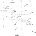
- FIG. 6 is a message flow sequence, indicated generally by the reference numeral 60, in accordance with an example embodiment.
- the message flow sequence 60 is an example implementation of the algorithm 30 described above and may be implemented using the system 50.
- the message flow sequence 60 shows messages transmitted between a first user device UE (such as the first user device 44), a first (serving) base station BS1 (such as the first communication node 42), a second base station BS2 (such as the second communication node 52) and a location management function LMF.
- the second base station BS2 may be a neighbour base station.
- the message flow sequence 60 starts with the LMF sending configuration instructions 61 to the first communication node BS1 (and optionally to the second communication node BS2) requesting measurement reports, such as the measurement reports discussed above with reference to the algorithm 30.
- the serving base station BS1 sends a positioning reference signal (PRS) to user devices served by the BS1, including the first user device UE.
- PRS positioning reference signal
- the first user device UE On receipt of the PRS signal, the first user device UE determines a downlink (DL) measurement (such downlink time delay or time of arrival data) and provides that DL measurement to the serving base station in a message 63a. That downlink data is provided by the serving base station to the LMF in a message 63b.
- DL downlink
- That downlink data is provided by the serving base station to the LMF in a message 63b.
- the receipt of the message 63b at the LMF is an example of the operation 32 of the algorithm 30 described above.
- the LMF also sends an SRS transmission request message 64a to the serving base station BS1, which transmission request is sent by the serving base station to the first user device UE in a message 64b.
- the UE provides a sounding reference signal (SRS) transmission that is received at the serving base station BS1 (message 65a) and is also received at the second base station BS2 (message 65b).
- SRS sounding reference signal
- Both the serving base station BS1 and the second base station BS2 generate uplink measurements (e.g. uplink time difference of arrival measurements) based on the received SRS transmissions from both the first user device and the second user device.
- First uplink measurements are sent by the serving base station to the LMF in message 66a and second uplink measurement are sent by the second base station BS2 to the LMF in message 66b.
- the receipt of the message 66a at the LMF is an example of the operation 34 of the algorithm 30 described above.
- the location management function LMF determines an integrity of the measurement data for each user device based on a comparison of said uplink and downlink measurement data received in the messages 63b, 66a and 66b.
- An integrity verification notification (such as a flag) maybe set by the LMF based on the determined integrity and may be provided to the serving base station BS1 as an integrity verification notification signal 67.
- FIG. 7 is a message flow sequence, indicated generally by the reference numeral 70, in accordance with an example embodiment.
- the message flow sequence 70 shows messages transmitted between the first (serving) user device UE, the first (serving) base station BS1, the second base station BS2 and the location management function LMF of the message flow sequence 60 and a second user device.
- the second user device is a malicious user device.
- the message flow sequence 70 starts with the LMF sending the configuration instructions 61 to the first communication node BS1 (and optionally to the second communication node BS2) requesting measurement reports, such as the measurement reports discussed above with reference to the algorithm 30.
- the serving base station BS1 sends a positioning reference signal (PRS) to user devices served by the BS1, including the first user device and the second user device.
- PRS positioning reference signal
- the first user device determines a downlink (DL) measurement are provides that DL measurement to the serving base station in the message 63a discussed above.
- the second user device provides DL measurement data to the serving base station in a message 73a.
- the downlink measurement data provided by the second user device in the message 73a may be faked or falsified in some way.
- That downlink data received by the serving base station in the messages 63a and 73a are provided to the LMF in a message 73b.
- the receipt of the message 73b at the LMF is an example of the operation 32 of the algorithm 30 described above.
- the LMF also sends the SRS transmission request message 64a to the serving base station BS1, which transmission request is sent by the serving base station to the first user device in the message 64b and to the second user device in a message 74.
- the first UE In response to the SRS transmission request, the first UE provides a sounding reference signal (SRS) transmission that is received at the serving base station BS1 (message 65a) and is also received at the second base station BS2 (message 65b).
- the second user device provides an SRS transmission that is received at the serving base station (message 75a) and is also received at the second base station BS2 (message 75b)
- Both the serving base station BS1 and the second base station BS2 generate uplink measurements (e.g. uplink time difference of arrival measurements) based on the received SRS transmission.
- First uplink measurements are sent by the serving base station to the LMF in message 76a and second uplink measurement are sent by the second base station BS2 to the LMF in message 76b.
- the receipt of the message 66a at the LMF is an example of the operation 34 of the algorithm 30 described above.
- the location management function LMF determines an integrity of the measurement data based on a comparison of said uplink and downlink measurement data for both user devices received in the messages 73b, 76a and 76b.
- An integrity verification notification (such as a flag) may be set for each user device by the LMF based on the determine integrity and maybe provided as to the serving base station BS1 as an integrity verification notification signal 67.
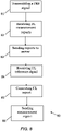
- FIG. 8 is a flow chart showing an algorithm, indicated generally by the reference numeral 80, in accordance with an example embodiment.
- the algorithm 80 may be implemented at a communication node, such as the serving base station BS1 of the message flow sequences 60 and 70.
- the algorithm 80 starts at operation 81, where a positioning reference signal (PRS) is transmitted by a communication node.
- PRS positioning reference signal
- one or more downlink measurement report(s) are received at the communication node from one or more user devices.
- the downlink measurement report(s) include downlink measurement data generated at a user device in response to the positioning reference signal transmitted in the operation 81.
- the downlink measurement data may be based on time delay data, but other data may be used, such as angle data, as discussed further below.
- a first measurement report is sent to a server (e.g. a location management server).
- the first measurement report includes the downlink measurement report(s) received in the operation 82.
- an uplink reference signal transmission (e.g. a sounding reference signal) is received from the user device(s).
- an uplink measurement report is generated at operation 85.
- the uplink measurement report includes uplink measurement data generated in response to the received uplink reference signal(s).
- a measurement report is sent to the server (e.g. the LMF), wherein the second measurement report includes the uplink measurement report generated in the operation 85.
- the server e.g. the LMF
- the user of uplink and downlink timing data is not the only mechanism by which positioning and position integrity can be verified.
- angle or arrival (AoA) and/or angle of departure (AoD) data may be used in the algorithms 30 and 80, as discussed in detail below.
- FIG. 9 is a block diagram of system, indicated generally by the reference numeral 90, in accordance with an example embodiment.
- the system 90 comprises a first communication node 91 and a second communication node 92 (similar to the first and second communication nodes 42 and 52 described above).
- the system 90 further comprises a first user device 93 (similar to the first user device 44 described above) and may comprise malicious (or fake) user device 94.
- Both the first and second communication nodes 91 and 92 are in two-way communication with the first user device 93 (and may be in two-way communication with the malicious user device 94).
- transmissions from the first user device 93 arrive at the first communication node 91 at a first angle 01, and arrive at the second communication node 92 at a second angle ⁇ 2.
- Those angles are the angles of arrival (AoA) of the respective transmissions.
- the distance between the first communication node 91 and the first user device 93 is given by di and the distance between the second communication node 92 and the first user device 93 is given by d2.
- a location management function (such as the LMF 24 of the system 20) can investigate the angle and distance data relating to a user device using triangle rules, as discussed further below.
- FIG. 10 is a flow chart showing an algorithm, indicated generally by the reference numeral 100, in accordance with an example embodiment.
- the algorithm 100 may be implemented using the system 90 described above.
- the algorithm 100 starts at operation 102, where the first angle 01 between the user device, the first communication node and the second communication node is determined and the second angle ⁇ 2 between the user device, the second communication node and the first communication node is determined.
- the first and second angles may bebased on angle of arrival and/or angle of departure data.
- a first distance (di) between the first communication node and the user device is determined and a second distance (d2) between the second communication node and the user device is determined.
- the first and second distances may be determined based on time delay data, as discussed further below.
- an integrity of the measurement data determined in the operations 102 and 104 may be determined based on whether the first and second angles and the first and second distances are consistent.
- the time of arrival measurements may be made in terms of time difference or RX time stamps and the absolute travel time are separately calculated.
- round-trip time (RTT) measurement gives absolute travel time.
- TTT round-trip time
- a location management function can directly apply the measurements outlined above as part of a checking algorithm.
- a malicious used device might seek to fake or conceal its locations. If so, it may be difficult for the malicious used device to provide data to the communication nodes that will result in the equation (2) above being satisfied.
- test in (2) set out above is applicable as long as the malicious user device 94 transmits a signal. It does not require any measurements from the malicious user device 94 side that may want to hide itself.
- the principles described above with reference to the system 90 may be used in the algorithm 30 described above.
- the uplink and downlink measurement data received in the operation 32 may include angle of arrival and angle of departure data.
- the integrity of the measurement data may be determined in the operation 36 based (at least in part) on whether the angle of arrival and angle of departure data are consistent, as discussed above.
- FIG. 11 is a block diagram of a system, indicated generally by the reference numeral 110, in accordance with an example embodiment.
- the system 110 comprises the first communication node 91, the second communication node 92 and the first user device 93 described above and may comprise the malicious (or fake) user device 94 described above. Both the first and second communication nodes 91 and 92 are in two-way communication with the first user device 93 (and may be in two-way communication with the malicious user device 94).
- transmissions from the first user device 93 arrive at the first communication node 91 at a first angle 01, and arrive at the second communication node 92 at a second angle ⁇ 2.
- Those angles are the angles of arrival (AoA) of the respective transmissions at the communication nodes.
- An angle between the first communication node, the first user device and the second communication node is labelled as ⁇ UE .
- the angle ⁇ UE may be determined based on angle of arrival and/or angle of departure data at the first user device 93.
- the distance between the first communication node 91 and the first user device 93 is expressed as ⁇ t 1 and the distance between the second communication node 92 and the first user device 93 is expressed as ⁇ t 2 .
- FIG. 12 is a flow chart showing an algorithm, indicated generally by the reference numeral 120, in accordance with an example embodiment.
- the algorithm 120 may be implemented using the system 110 described above.
- the algorithm 120 starts at operation 122, where a first angle ⁇ 1 between the user device, the first communication node and the second communication node is determined and a second angle ⁇ 2 between the user device, the second communication node and the first communication node is determined.
- the first and second angles may be based on angle of arrival and/or angle of departure data.
- a third angle ⁇ UE between the first communication node, the user device and the second communicate node is determined.
- the third angle may be determined based on angle of arrival and/or angle of departure data at the respective user device.
- a malicious used device might seek to fake or conceal its locations. If so, it may be difficult for the malicious used device to provide data to the communication nodes that will result in the equation (3) above being satisfied.
- an integrity determination identifies a malicious device
- an attempt may be made to determine a true location of that device. In this way, a malicious (or suspected malicious) device may be tracked.
- FIG. 13 is a flow chart showing an algorithm, indicated generally by the reference numeral 130, in accordance with an example embodiment.
- the algorithm 130 starts at operation 132, where a malicious device is identified.
- a malicious device For example, one or more of the algorithm described above may be used to identify a malicious device.
- a position estimate for the device identified at the operation 132 is determined.
- the position estimate obtained in the operation 134 may be based on data that is difficult to fake or spoof (such as angle of arrival data for signals received at a communication node from the malicious (or a suspected malicious) device).
- FIG. 14 is a block diagram, indicated generally by the reference numeral 140, of a system in accordance with an example embodiment.
- the system 140 comprises a first communication node 141 and a second communication node 142 (similar to the first and second communication nodes 91 and 92 described above).
- the system 140 further comprises a first user device 143 (similar to the first user device 93 described above) and may comprise a malicious user device 144 (similar to the device 94 described above). Both the first and second communication nodes 141 and 142 are in two-way communication with the first user device 143 and the malicious user device 144.
- ⁇ 1 f denote the angle of arrival (AoA) of communications from the malicious user device 144 at the first communication node 141
- ⁇ 2 f denote the angle of arrive of communications from the malicious user device 144 at the second communication node 142
- d Bs denote the distance between the first and second communication nodes.
- an estimate of the position of the malicious (or suspected malicious) user device 144 can be determined based only on angle of arrival data determined at the first and second communication nodes (which data are difficult to fake or spoof) and the distance between the first and second communication nodes (which distance is typically know precisely).
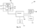
- FIG. 15 is a schematic diagram of components of one or more of the example embodiments described previously, which hereafter are referred to generically as a processing system 300.
- the processing system 300 may, for example, be the apparatus referred to in the claims below.
- the processing system 300 may have a processor 302, a memory 304 closely coupled to the processor and comprised of a RAM 314 and a ROM 312, and, optionally, a user input 310 and a display 318.
- the processing system 300 may comprise one or more network/apparatus interfaces 308 for connection to a network/apparatus, e.g. a modem which may be wired or wireless.
- the network/apparatus interface 308 may also operate as a connection to other apparatus such as device/apparatus which is not network side apparatus. Thus, direct connection between devices/apparatus without network participation is possible.
- the processor 302 is connected to each of the other components in order to control operation thereof.
- the memory 304 may comprise a non-volatile memory, such as a hard disk drive (HDD) or a solid state drive (SSD).
- the ROM 312 of the memory 304 stores, amongst other things, an operating system 315 and may store software applications 316.
- the RAM 314 of the memory 304 is used by the processor 302 for the temporary storage of data.
- the operating system 315 may contain code which, when executed by the processor implements aspects of the algorithms and message flow sequences 30, 60, 70, 80, 100, 120 and 130 described above. Note that in the case of small device/apparatus the memory can be most suitable for small size usage i.e. not always a hard disk drive (HDD) or a solid state drive (SSD) is used.
- HDD hard disk drive
- SSD solid state drive
- the processor 302 may take any suitable form. For instance, it may be a microcontroller, a plurality of microcontrollers, a processor, or a plurality of processors.
- the processing system 300 may be a standalone computer, a server, a console, or a network thereof.
- the processing system 300 and needed structural parts may be all inside device/apparatus such as IoT device/apparatus i.e. embedded to very small size.
- the processing system 300 may also be associated with external software applications. These may be applications stored on a remote server device/apparatus and may run partly or exclusively on the remote server device/apparatus. These applications may be termed cloud-hosted applications.
- the processing system 300 may be in communication with the remote server device/apparatus in order to utilize the software application stored there.
- FIGS. 16A and 16B show tangible media, respectively a removable memory unit 365 and a compact disc (CD) 368, storing computer-readable code which when run by a computer may perform methods according to example embodiments described above.
- the removable memory unit 365 may be a memory stick, e.g. a USB memory stick, having internal memory 366 storing the computer-readable code.
- the internal memory 366 may be accessed by a computer system via a connector 367.
- the CD 368 may be a CD-ROM or a DVD or similar. Other forms of tangible storage media may be used.
- Tangible media can be any device/apparatus capable of storing data/information which data/information can be exchanged between devices/apparatus/network.
- Embodiments of the present invention may be implemented in software, hardware, application logic or a combination of software, hardware and application logic.
- the software, application logic and/or hardware may reside on memory, or any computer media.
- the application logic, software or an instruction set is maintained on any one of various conventional computer-readable media.
- a "memory" or “computer-readable medium” may be any non-transitory media or means that can contain, store, communicate, propagate or transport the instructions for use by or in connection with an instruction execution system, apparatus, or device, such as a computer.
- references to, where relevant, "computer-readable medium”, “computer program product”, “tangibly embodied computer program” etc., or a “processor” or “processing circuitry” etc. should be understood to encompass not only computers having differing architectures such as single/multi-processor architectures and sequencers/parallel architectures, but also specialised circuits such as field programmable gate arrays FPGA, application specify circuits ASIC, signal processing devices/apparatus and other devices/apparatus. References to computer program, instructions, code etc.
- programmable processor firmware such as the programmable content of a hardware device/apparatus as instructions for a processor or configured or configuration settings for a fixed function device/apparatus, gate array, programmable logic device/apparatus, etc.
Landscapes
- Engineering & Computer Science (AREA)
- Physics & Mathematics (AREA)
- General Physics & Mathematics (AREA)
- Radar, Positioning & Navigation (AREA)
- Remote Sensing (AREA)
- Computer Security & Cryptography (AREA)
- Computer Networks & Wireless Communication (AREA)
- Signal Processing (AREA)
- Environmental & Geological Engineering (AREA)
- Mobile Radio Communication Systems (AREA)
- Position Fixing By Use Of Radio Waves (AREA)
- Emergency Alarm Devices (AREA)
Applications Claiming Priority (1)
| Application Number | Priority Date | Filing Date | Title |
|---|---|---|---|
| FI20205951A FI20205951A1 (en) | 2020-09-30 | 2020-09-30 | POSITIONING OF A DEVICE |
Publications (3)
| Publication Number | Publication Date |
|---|---|
| EP3988959A2 true EP3988959A2 (de) | 2022-04-27 |
| EP3988959A3 EP3988959A3 (de) | 2022-06-01 |
| EP3988959B1 EP3988959B1 (de) | 2025-12-17 |
Family
ID=78413569
Family Applications (1)
| Application Number | Title | Priority Date | Filing Date |
|---|---|---|---|
| EP21199800.0A Active EP3988959B1 (de) | 2020-09-30 | 2021-09-29 | Vorrichtungspositionierung |
Country Status (4)
| Country | Link |
|---|---|
| US (2) | US11561277B2 (de) |
| EP (1) | EP3988959B1 (de) |
| CN (1) | CN114363798B (de) |
| FI (1) | FI20205951A1 (de) |
Families Citing this family (3)
| Publication number | Priority date | Publication date | Assignee | Title |
|---|---|---|---|---|
| EP4371327A4 (de) * | 2021-07-12 | 2025-06-11 | Nokia Technologies Oy | Positionierung |
| CN118235376A (zh) * | 2022-10-21 | 2024-06-21 | 北京小米移动软件有限公司 | 定位完整性的传输方法、装置、设备及介质 |
| WO2026035384A1 (en) * | 2024-08-08 | 2026-02-12 | Qualcomm Incorporated | Detecting position spoofing |
Family Cites Families (14)
| Publication number | Priority date | Publication date | Assignee | Title |
|---|---|---|---|---|
| US8437772B2 (en) | 2009-09-15 | 2013-05-07 | Qualcomm Incorporated | Transmitter position integrity checking |
| CN103384376B (zh) * | 2012-05-04 | 2016-12-14 | 华为技术有限公司 | 链路覆盖问题确定方法、装置与系统 |
| US9674755B2 (en) | 2014-01-15 | 2017-06-06 | Qualcomm Incorporated | Intra and inter-frequency handover in LTE with uplink and downlink metrics |
| EP3165022B1 (de) | 2014-07-02 | 2020-06-03 | Telefonaktiebolaget LM Ericsson (publ) | Netzwerkknoten und verfahren zum treffen einer mobilitätsentscheidung unter berücksichtigung der strahlformungsfähigkeiten der benachbarten knoten |
| WO2017190274A1 (zh) * | 2016-05-03 | 2017-11-09 | 华为技术有限公司 | 一种资源分配方法、网络侧设备和终端设备 |
| US11509364B2 (en) * | 2017-03-13 | 2022-11-22 | Qualcomm Incorporated | Techniques and apparatuses for uplink precoder determination using downlink reference signals or downlink precoder determination using uplink reference signals |
| CN110022523B (zh) | 2018-01-05 | 2022-04-12 | 华为技术有限公司 | 用于终端设备定位的方法、装置及系统 |
| EP4141468B1 (de) | 2018-09-28 | 2026-03-18 | Apple Inc. | Techniken zur verbesserung der positionierungsleistung von new radio (nr) |
| US12041578B2 (en) * | 2018-10-31 | 2024-07-16 | Qualcomm Incorporated | System and methods for supporting uplink and downlink positioning procedures in a wireless network |
| US11330632B2 (en) * | 2019-01-18 | 2022-05-10 | Qualcomm Incorporated | Positioning using random access channel (RACH) |
| US11044581B2 (en) * | 2019-01-21 | 2021-06-22 | Qualcomm Incorporated | Signaling for round trip time (RTT) based positioning using stronger path tracking |
| US11206632B2 (en) | 2019-02-14 | 2021-12-21 | Samsung Electronics Co., Ltd. | Position of user equipment |
| US11382058B2 (en) * | 2019-02-14 | 2022-07-05 | Qualcomm Incorporated | Systems and methods for location by a mobile device in a fifth generation wireless network |
| US12058640B2 (en) * | 2019-03-25 | 2024-08-06 | Sony Group Corporation | Methods and devices for dual-direction positioning of a device |
-
2020
- 2020-09-30 FI FI20205951A patent/FI20205951A1/en not_active Application Discontinuation
-
2021
- 2021-09-29 EP EP21199800.0A patent/EP3988959B1/de active Active
- 2021-09-30 CN CN202111165071.3A patent/CN114363798B/zh active Active
- 2021-09-30 US US17/490,184 patent/US11561277B2/en active Active
-
2022
- 2022-12-27 US US18/089,331 patent/US12248087B2/en active Active
Also Published As
| Publication number | Publication date |
|---|---|
| US12248087B2 (en) | 2025-03-11 |
| CN114363798A (zh) | 2022-04-15 |
| US20230184879A1 (en) | 2023-06-15 |
| EP3988959A3 (de) | 2022-06-01 |
| CN114363798B (zh) | 2023-03-28 |
| US20220099791A1 (en) | 2022-03-31 |
| FI20205951A1 (en) | 2022-03-31 |
| US11561277B2 (en) | 2023-01-24 |
| EP3988959B1 (de) | 2025-12-17 |
Similar Documents
| Publication | Publication Date | Title |
|---|---|---|
| US12248087B2 (en) | Device positioning | |
| US9453905B2 (en) | Geolocation | |
| EP2022278B1 (de) | Positionsschätzung mittels funkausbreitungsmerkmalen eines wlan-zugangs in einem wlan-positionierungssystem | |
| EP2022281B1 (de) | Berechnung der qualität von wlan-zugangspunktcharakterisierung zur verwendung in einem wlan-positionierungssystem | |
| CN101334467B (zh) | 测位系统、测位方法 | |
| Yu et al. | TOA-based distributed localisation with unknown internal delays and clock frequency offsets in wireless sensor networks | |
| US8340022B2 (en) | Wireless location determination system and method | |
| US20180231633A1 (en) | Determining a location of a transmitter device | |
| Cai et al. | Self-deployable indoor localization with acoustic-enabled IoT devices exploiting participatory sensing | |
| US10356741B2 (en) | Fingerprint positioning for mobile terminals | |
| CN101365958A (zh) | 用于无线装置上发生的事件的地理位置概算的设备和方法 | |
| WO2018029298A1 (en) | Position detection of user equipment within a wireless telecommunications network | |
| CN107113762A (zh) | 一种定位方法、定位服务器及定位系统 | |
| GB2631357A (en) | Configuring participation in a radio sensing operation | |
| He et al. | Modeling and performance analysis of blockchain-aided secure TDOA localization under random internet-of-vehicle networks | |
| CN105992337A (zh) | 一种伪基站定位方法及设备 | |
| Yi et al. | Cellular-assisted, deep learning based COVID-19 contact tracing | |
| Malaney | Securing Wi-Fi networks with position verification: extended version | |
| Chandrasekaran et al. | Decode: Exploiting shadow fading to detect comoving wireless devices | |
| JP4938778B2 (ja) | 移動電気通信ネットワークにおける方法および配置構成 | |
| Lee et al. | Bilatangulation: A Novel Measurement Error Compensation Method for Wi-Fi Indoor Positioning With Two Anchors | |
| Etzlinger et al. | WIP: Distance Estimation for Contact Tracing--A Measurement Study of BLE and UWB Traces | |
| CN102547560B (zh) | 在单频网络中由终端识别发射机的方法 | |
| CN119422416A (zh) | 用于分层测量机制的设备、方法、装置和计算机可读介质 | |
| Wei et al. | Analysis of location spoofing identification in cellular networks |
Legal Events
| Date | Code | Title | Description |
|---|---|---|---|
| PUAI | Public reference made under article 153(3) epc to a published international application that has entered the european phase |
Free format text: ORIGINAL CODE: 0009012 |
|
| STAA | Information on the status of an ep patent application or granted ep patent |
Free format text: STATUS: THE APPLICATION HAS BEEN PUBLISHED |
|
| AK | Designated contracting states |
Kind code of ref document: A2 Designated state(s): AL AT BE BG CH CY CZ DE DK EE ES FI FR GB GR HR HU IE IS IT LI LT LU LV MC MK MT NL NO PL PT RO RS SE SI SK SM TR |
|
| PUAL | Search report despatched |
Free format text: ORIGINAL CODE: 0009013 |
|
| AK | Designated contracting states |
Kind code of ref document: A3 Designated state(s): AL AT BE BG CH CY CZ DE DK EE ES FI FR GB GR HR HU IE IS IT LI LT LU LV MC MK MT NL NO PL PT RO RS SE SI SK SM TR |
|
| RIC1 | Information provided on ipc code assigned before grant |
Ipc: H04W 24/10 20090101ALN20220426BHEP Ipc: H04W 12/104 20210101ALI20220426BHEP Ipc: G01S 5/12 20060101ALI20220426BHEP Ipc: G01S 5/02 20100101ALI20220426BHEP Ipc: G01S 5/00 20060101AFI20220426BHEP |
|
| STAA | Information on the status of an ep patent application or granted ep patent |
Free format text: STATUS: REQUEST FOR EXAMINATION WAS MADE |
|
| 17P | Request for examination filed |
Effective date: 20221201 |
|
| RBV | Designated contracting states (corrected) |
Designated state(s): AL AT BE BG CH CY CZ DE DK EE ES FI FR GB GR HR HU IE IS IT LI LT LU LV MC MK MT NL NO PL PT RO RS SE SI SK SM TR |
|
| RIC1 | Information provided on ipc code assigned before grant |
Ipc: G01S 5/00 20060101AFI20250829BHEP Ipc: G01S 5/02 20100101ALI20250829BHEP Ipc: G01S 5/12 20060101ALI20250829BHEP Ipc: H04W 12/104 20210101ALI20250829BHEP Ipc: H04W 12/122 20210101ALI20250829BHEP Ipc: H04W 12/108 20210101ALI20250829BHEP Ipc: H04W 24/10 20090101ALN20250829BHEP |
|
| GRAP | Despatch of communication of intention to grant a patent |
Free format text: ORIGINAL CODE: EPIDOSNIGR1 |
|
| STAA | Information on the status of an ep patent application or granted ep patent |
Free format text: STATUS: GRANT OF PATENT IS INTENDED |
|
| RIC1 | Information provided on ipc code assigned before grant |
Ipc: G01S 5/00 20060101AFI20250922BHEP Ipc: G01S 5/02 20100101ALI20250922BHEP Ipc: G01S 5/12 20060101ALI20250922BHEP Ipc: H04W 12/104 20210101ALI20250922BHEP Ipc: H04W 12/122 20210101ALI20250922BHEP Ipc: H04W 12/108 20210101ALI20250922BHEP Ipc: H04W 24/10 20090101ALN20250922BHEP |
|
| GRAS | Grant fee paid |
Free format text: ORIGINAL CODE: EPIDOSNIGR3 |
|
| GRAA | (expected) grant |
Free format text: ORIGINAL CODE: 0009210 |
|
| STAA | Information on the status of an ep patent application or granted ep patent |
Free format text: STATUS: THE PATENT HAS BEEN GRANTED |
|
| RIC1 | Information provided on ipc code assigned before grant |
Ipc: G01S 5/00 20060101AFI20251013BHEP Ipc: G01S 5/02 20100101ALI20251013BHEP Ipc: G01S 5/12 20060101ALI20251013BHEP Ipc: H04W 12/104 20210101ALI20251013BHEP Ipc: H04W 12/122 20210101ALI20251013BHEP Ipc: H04W 12/108 20210101ALI20251013BHEP Ipc: H04W 24/10 20090101ALN20251013BHEP |
|
| INTG | Intention to grant announced |
Effective date: 20251023 |
|
| RIC1 | Information provided on ipc code assigned before grant |
Ipc: G01S 5/00 20060101AFI20251017BHEP Ipc: G01S 5/02 20100101ALI20251017BHEP Ipc: G01S 5/12 20060101ALI20251017BHEP Ipc: H04W 12/104 20210101ALI20251017BHEP Ipc: H04W 12/122 20210101ALI20251017BHEP Ipc: H04W 12/108 20210101ALI20251017BHEP Ipc: H04W 24/10 20090101ALN20251017BHEP |
|
| AK | Designated contracting states |
Kind code of ref document: B1 Designated state(s): AL AT BE BG CH CY CZ DE DK EE ES FI FR GB GR HR HU IE IS IT LI LT LU LV MC MK MT NL NO PL PT RO RS SE SI SK SM TR |
|
| REG | Reference to a national code |
Ref country code: CH Ref legal event code: F10 Free format text: ST27 STATUS EVENT CODE: U-0-0-F10-F00 (AS PROVIDED BY THE NATIONAL OFFICE) Effective date: 20251217 Ref country code: GB Ref legal event code: FG4D |
|
| REG | Reference to a national code |
Ref country code: DE Ref legal event code: R096 Ref document number: 602021044475 Country of ref document: DE |