EP3988854A1 - Closure unit for a ventilation device - Google Patents
Closure unit for a ventilation device Download PDFInfo
- Publication number
- EP3988854A1 EP3988854A1 EP20203051.6A EP20203051A EP3988854A1 EP 3988854 A1 EP3988854 A1 EP 3988854A1 EP 20203051 A EP20203051 A EP 20203051A EP 3988854 A1 EP3988854 A1 EP 3988854A1
- Authority
- EP
- European Patent Office
- Prior art keywords
- duct
- air
- exhaust air
- heat exchangers
- closure unit
- Prior art date
- Legal status (The legal status is an assumption and is not a legal conclusion. Google has not performed a legal analysis and makes no representation as to the accuracy of the status listed.)
- Pending
Links
- 238000009423 ventilation Methods 0.000 title claims abstract description 64
- 238000011084 recovery Methods 0.000 claims description 7
- 238000007599 discharging Methods 0.000 claims description 6
- 238000000034 method Methods 0.000 claims description 4
- 238000004519 manufacturing process Methods 0.000 description 4
- 241001136792 Alle Species 0.000 description 1
- 238000001816 cooling Methods 0.000 description 1
- 230000001419 dependent effect Effects 0.000 description 1
- 230000000694 effects Effects 0.000 description 1
- 239000012530 fluid Substances 0.000 description 1
- 238000009434 installation Methods 0.000 description 1
- 239000007788 liquid Substances 0.000 description 1
- 238000012423 maintenance Methods 0.000 description 1
- 239000002184 metal Substances 0.000 description 1
- 238000011144 upstream manufacturing Methods 0.000 description 1
Images


Classifications
-
- F—MECHANICAL ENGINEERING; LIGHTING; HEATING; WEAPONS; BLASTING
- F24—HEATING; RANGES; VENTILATING
- F24F—AIR-CONDITIONING; AIR-HUMIDIFICATION; VENTILATION; USE OF AIR CURRENTS FOR SCREENING
- F24F13/00—Details common to, or for air-conditioning, air-humidification, ventilation or use of air currents for screening
- F24F13/08—Air-flow control members, e.g. louvres, grilles, flaps or guide plates
- F24F13/10—Air-flow control members, e.g. louvres, grilles, flaps or guide plates movable, e.g. dampers
- F24F13/14—Air-flow control members, e.g. louvres, grilles, flaps or guide plates movable, e.g. dampers built up of tilting members, e.g. louvre
- F24F13/1426—Air-flow control members, e.g. louvres, grilles, flaps or guide plates movable, e.g. dampers built up of tilting members, e.g. louvre characterised by actuating means
-
- F—MECHANICAL ENGINEERING; LIGHTING; HEATING; WEAPONS; BLASTING
- F24—HEATING; RANGES; VENTILATING
- F24F—AIR-CONDITIONING; AIR-HUMIDIFICATION; VENTILATION; USE OF AIR CURRENTS FOR SCREENING
- F24F12/00—Use of energy recovery systems in air conditioning, ventilation or screening
- F24F12/001—Use of energy recovery systems in air conditioning, ventilation or screening with heat-exchange between supplied and exhausted air
- F24F12/006—Use of energy recovery systems in air conditioning, ventilation or screening with heat-exchange between supplied and exhausted air using an air-to-air heat exchanger
-
- F—MECHANICAL ENGINEERING; LIGHTING; HEATING; WEAPONS; BLASTING
- F24—HEATING; RANGES; VENTILATING
- F24F—AIR-CONDITIONING; AIR-HUMIDIFICATION; VENTILATION; USE OF AIR CURRENTS FOR SCREENING
- F24F13/00—Details common to, or for air-conditioning, air-humidification, ventilation or use of air currents for screening
- F24F13/08—Air-flow control members, e.g. louvres, grilles, flaps or guide plates
- F24F13/10—Air-flow control members, e.g. louvres, grilles, flaps or guide plates movable, e.g. dampers
-
- F—MECHANICAL ENGINEERING; LIGHTING; HEATING; WEAPONS; BLASTING
- F24—HEATING; RANGES; VENTILATING
- F24F—AIR-CONDITIONING; AIR-HUMIDIFICATION; VENTILATION; USE OF AIR CURRENTS FOR SCREENING
- F24F12/00—Use of energy recovery systems in air conditioning, ventilation or screening
- F24F12/001—Use of energy recovery systems in air conditioning, ventilation or screening with heat-exchange between supplied and exhausted air
- F24F2012/007—Use of energy recovery systems in air conditioning, ventilation or screening with heat-exchange between supplied and exhausted air using a by-pass for bypassing the heat-exchanger
-
- Y—GENERAL TAGGING OF NEW TECHNOLOGICAL DEVELOPMENTS; GENERAL TAGGING OF CROSS-SECTIONAL TECHNOLOGIES SPANNING OVER SEVERAL SECTIONS OF THE IPC; TECHNICAL SUBJECTS COVERED BY FORMER USPC CROSS-REFERENCE ART COLLECTIONS [XRACs] AND DIGESTS
- Y02—TECHNOLOGIES OR APPLICATIONS FOR MITIGATION OR ADAPTATION AGAINST CLIMATE CHANGE
- Y02B—CLIMATE CHANGE MITIGATION TECHNOLOGIES RELATED TO BUILDINGS, e.g. HOUSING, HOUSE APPLIANCES OR RELATED END-USER APPLICATIONS
- Y02B30/00—Energy efficient heating, ventilation or air conditioning [HVAC]
- Y02B30/56—Heat recovery units
Definitions
- the present invention relates to a closure unit of a ventilation device, in particular a ventilation device with heat recovery, a ventilation device and a method for operating a ventilation device of a building.
- Buildings are increasingly equipped with ventilation systems with heat recovery.
- the outside air that is brought into the building from outside and the exhaust air that is brought outside from the inside of the building are guided through a common heat exchanger.
- heat is transferred from one air volume flow to the other.
- bypass ducts are provided in order to direct one of the two air volume flows inwards or outwards without passing through the heat exchanger.
- the passage through the heat exchanger is closed by a closure device.
- This closure device is usually a flap or a roller shutter.
- DE 10 2013 216 306 A1 uses a first damper in the bypass duct and a second damper in the supply air duct. The two flaps are operated separately from each other.
- EP 0 044 560 B1 discloses a ventilation device with a heat exchanger and a bypass, the device having individually actuated flaps.
- EP 1 132 690 B1 shows two heat exchangers connected in series, two bypass channels and several individually operated flaps.
- EP 2 498 014 B1 discloses a heat recovery module with a roller shutter which when rolled up blocks the bypass and unblocks the heat exchanger and when unrolled opens the bypass but blocks the heat exchanger.
- EP 1 962 031 A2 shows a heat recovery module with a flap and a slide that form a structural unit. Their adjustment movements are positively coupled, which is achieved by connecting the parts that are aligned perpendicular to one another. This structural unit is directly adjacent to the heat exchanger bypass device without any further lines or channels.
- Heat exchangers connected in parallel are also known.
- U.S. 2007/0158049 A1 discloses, for example, such a ventilation unit with a plurality of heat exchangers arranged next to one another, which are connected in parallel and are correspondingly flowed through in parallel.
- a common bypass duct is arranged next to the heat exchangers.
- DE 10 2011 114 885 A1 describes a heat exchanger arrangement with a gaseous and a liquid fluid.
- the arrangement has two parallel flow heat exchangers, which are arranged spatially offset one behind the other.
- Two bypass channels enable air to be supplied to and removed from the heat exchangers.
- Each bypass channel has its own, separately operated shutter.
- the known devices still require a relatively large amount of space.
- the use of several heat exchangers has the disadvantage that more bypass ducts and dampers are required, which increases space requirements and manufacturing costs, in particular because of the increased number of motors for actuating the dampers.
- the closure unit of a ventilation device has at least two pivotably arranged flaps for closing one ventilation duct each.
- the two flaps are moveable by means of a common shaft defining a common pivot axis.
- the two flaps are therefore positively coupled and can be operated simultaneously using a single motor.
- This locking unit is suitable for a wide variety of applications in ventilation devices in which two ventilation ducts have to be closed or opened at the same time. Depending on the position of the flaps, one ventilation duct can be opened and the other closed. However, both ventilation ducts are preferably closed or opened at the same time.
- This closure unit serves, for example, as a double bypass damper with a single motor.
- this closure unit is preferably used in a ventilation device which nevertheless has a bypass function without a separate bypass duct. This is explained in more detail later in the text.
- This closure unit is particularly suitable for use in ventilation devices with heat recovery, in particular by means of heat exchangers.
- heat exchangers There are preferably two or more heat exchangers, which are preferably operated in parallel. This is explained in more detail below in the text.
- the pivot axis of the closure unit according to the invention preferably runs centrally through the two flaps.
- the shaft can be operated manually. However, it is preferably driven by a motor.
- the motor is preferably arranged in the longitudinal direction of the shaft above or below the two flaps or in the middle between the two flaps. Since only a single motor needs to be used, manufacturing costs can be reduced.
- the arrangement above or below the flaps reduces the space requirement, in particular if a motor designed as flat as possible is used. This arrangement also allows optimal accessibility of the engine in a ventilation device, which greatly facilitates maintenance.
- the two flaps are preferably arranged at an angle of 90° to one another. If the two ventilation ducts run parallel to one another, with this 90° arrangement of the flaps, a first duct is closed by the first flap, while the second duct is opened by the second flap. If the ventilation ducts are arranged at an angle of 90° to one another, the ducts are closed or released together if the flaps are arranged at 90°. This 90° arrangement of the flaps thus enables use in differently arranged ducts. The same applies if the flaps are arranged parallel to one another, albeit with the opposite effect in their closing behavior.
- each of the two flaps forms a closure surface, with the two closure surfaces containing the pivot axis of the shaft. This arrangement facilitates inexpensive manufacture and requires relatively little space.
- the two flaps have a rectangular cross-section.
- the shape of the flap is preferably adapted to the shape of the channels to be closed.
- the closure unit has a first housing for pivotably receiving a first flap and a second housing for pivotably receiving a second flap.
- the shaft has an upper portion pivotally supported in the first housing and having a first end connected to the first door and a second end connected to the motor.
- the shaft also includes a lower portion having a first end connected to the first door and a second end connected to the second door. The second flap and/or the second end of the lower section of the shaft is pivoted in the second housing.
- the closure unit can be designed as a relatively simple and robust module that can be used as a structural unit in a ventilation device and, if necessary, can also be easily replaced as part of service work.
- This locking unit can be used in a wide variety of applications Use ventilation devices. However, it is preferably used in the ventilation device according to the invention described below.
- This ventilation device can be designed to be extremely compact and flat. The ventilation device nevertheless enables a large volume flow.
- a ventilation system of a building in particular in a central ventilation system of a building, preferably a residential or office building.
- the ventilation device according to the invention does not require an additional bypass channel.
- the two heat exchangers themselves form bypass channels, namely when only one of the two air volume flows flows through them and as a result no heat exchange can take place with the other air volume flow.
- the closure unit used in the ventilation device according to the invention can consist of two individually actuated or jointly actuated, in particular forcibly coupled, closure bodies.
- the closure unit according to the invention described above is preferably used.
- the closure unit is designed in such a way that it selectively only partially enables or prevents the air volume flows by only partially releasing or only partially closing the ducts or partial ducts.
- this arrangement thus makes it possible to guide the air volume flows with different parts through the two heat exchangers.
- the outside air can be routed 2/3 through the first heat exchanger and 1/3 through the second heat exchanger, in which case the exhaust air is routed 1/3 through the first heat exchanger and 2/3 through the second heat exchanger.
- the closure unit of the ventilation device according to the invention preferably has two closure bodies that can be actuated jointly by means of a common motor.
- the closure bodies can be flaps as in the device according to the invention. They can also be differently arranged flaps or other types of closure bodies.
- the channels are divided into sub-channels. That is, the outside air duct is divided into a first outside air sub-duct and a second outside air sub-duct, with the first outside air sub-duct leading into the first heat exchanger and the second outside air sub-duct leading into the second heat exchanger.
- the supply air duct is divided into a first supply air sub-duct and a second supply air sub-duct, with the first supply air sub-duct leading out of the first heat exchanger and the second supply air sub-duct leading out of the second heat exchanger.
- the exhaust air duct is divided into a first partial exhaust air duct and a second exhaust air partial duct, with the first exhaust air partial duct leading into the first heat exchanger and the second exhaust air partial duct leading into the second heat exchanger.
- the exhaust air duct is divided into a first exhaust air sub-duct and a second exhaust air sub-duct, with the first exhaust air sub-duct leading out of the first heat exchanger and the second exhaust air sub-duct leading out of the second heat exchanger.
- Those partial channels which are opened or closed by means of the closure unit preferably run offset from one another in the region of the closure unit at an angle of 90°.
- the flaps are preferably also arranged offset from one another at an angle of 90°, with one flap each being arranged in a partial channel.
- the partial channels all have the same cross-sectional area and preferably even the same cross-sectional shape.
- a first sub-channel has a smaller cross section than an associated second sub-channel, at least in the area of the closure device.
- the partial channel that is arranged upstream of the heat exchanger in the direction of flow is designed to be larger, so that the partial channel that follows after the heat exchanger in the direction of flow is smaller. This achieves an optimized flow behavior. The flow is improved and equal distribution in front of the heat exchanger and higher efficiency are obtained.
- the width of the partial channels is the same, but the height is different.
- At least one fan is preferably present. Preferably there are two fans; one for outside air or supply air and one for extract air or exhaust air.
- the closure unit simultaneously closes the first supply air sub-duct and the second exhaust air sub-duct or releases it, or the closure unit simultaneously closes the first outside air sub-duct and the second exhaust air sub-duct or releases it.
- the outside air duct feeds the outside air from the outside to the two heat exchangers
- the supply air duct leads the outside air from the heat exchangers into the interior of the building
- the exhaust air duct leads the exhaust air from the interior of the building to the two heat exchangers
- the exhaust air duct leads the exhaust air out of the heat exchanger to the outside.
- the shutter unit is optional all channels free or allows outside air flow through one of the two heat exchangers while preventing exhaust air flow through that one of the two heat exchangers while allowing exhaust air flow through the other of the two heat exchangers and preventing outside air flow through that other of the two heat exchangers .
- a simple closure unit for example with two flaps that can be actuated together and are preferably positively coupled, is sufficient to prevent heat exchange between the two air volume flows.
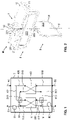
- figure 1 shows a schematic view of a ventilation device according to the invention for use in a ventilation system of a building, in particular in a central ventilation system.
- the ventilation device has a closed housing 7 which is designed as flat as possible.
- two heat exchangers 60, 61 are arranged in the housing 7 . They are preferably arranged side by side and operated in parallel.
- the heat exchangers 60, 61 are preferably plate heat exchangers of a known type or differently designed, as flat as possible heat exchangers of a known type.
- exhaust air The exhaust air discharged to the outside is called exhaust air
- supply air the outside air directed into the interior. If the two air volume flows of the outside air and the exhaust air flow through both heat exchangers 60, 61 simultaneously, heat transfer takes place in a known manner, which is used for heat recovery in winter and possibly also for cooling in summer. Depending on the time of year or temperature conditions, heat exchange is either not required or only required to a lesser extent.
- fans 80, 81 there is preferably at least one, preferably several fans 80, 81 present.
- the fans 80, 81 are preferably operated by means of a controller, preferably according to a program.
- a first and second outside air sub-duct 400, 401, a first and second supply air sub-duct 410, 411, a first and second exhaust air sub-duct 500, 501 and a first and second exhaust air sub-duct 510, 511 are present.
- the first sub-ducts 400, 410, 500, 510 are connected to the first heat exchanger 60 and the second sub-ducts 401, 411, 501, 511 to the second heat exchanger 61.
- closure unit M which closes two of the partial channels together.
- the closure unit M has two closure bodies, one of the closure bodies closing one of the two partial channels.
- the two closure bodies are flaps.
- the closure bodies are preferably motor-driven and can be actuated via a controller.
- the two closure bodies are arranged spatially separate from one another and are actuated simultaneously or one after the other by means of the control.
- the two closure bodies are arranged adjacent to one another.
- the two partial channels to be closed run in the area of the closure unit M, also called the closure module or module, and thus in the area of the closure body adjacent to one another, so that they can be closed and opened again together at the same time.
- the two partial channels can run parallel to one another. However, they preferably intersect, for which purpose they preferably run one above the other. In figure 1 this applies to the first supply air sub-duct 410 and the second exhaust air sub-duct 501. If these two sub-ducts are open, both the outside air volume flow and the exhaust air volume flow run through both heat exchangers 60, 61. The two heat exchangers 60, 61 are thus flowed through in parallel by the two air volume flows.
- the outside air volume flow can only flow through the second heat exchanger 61 and the exhaust air volume flow can only flow through the first heat exchanger 60 .
- the streams are thus "bypassed", i.e. guided past one another without a separate bypass channel having to be present for this purpose. There is no heat transfer between the two air volume flows.
- the closure unit can also be arranged on the other side of the heat exchangers 60, 61.
- the second outside air sub-duct 401 and the first exhaust air sub-duct 510 are arranged at an angle of 90° to one another and one above the other so that they can be closed together.
- the closure unit M can also close other combinations of first and second sub-ducts, as is easily recognizable for the person skilled in the art.
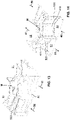
- a closure unit M according to the invention is shown, which can preferably be used in the described ventilation device according to the invention.
- this closure unit M can also be used in other ventilation devices in which two ducts arranged one above the other or next to one another are to be closed together and at the same time.
- the ducts cross at an angle of 90°. If they are arranged next to each other, they run parallel. In both cases, a pivot axis of the closure unit runs at an angle of 90° in relation to the longitudinal directions of the air ducts. In the case of air ducts arranged one above the other, the pivot axis runs vertically, in the case of air ducts arranged next to one another, it runs horizontally.
- the closure unit comprises a first motor unit 1, a first flap device 2 and a second flap device 3. It is preferably designed as a structural unit in the form of a module that can be installed as a whole in the ventilation device. In other embodiments, the parts are assembled individually or as sub-modules.
- the motor unit 1 has a motor 10 which is designed as flat as possible. It is held fixed on a frame 20 , 21 of the first flap device 2 . A power cable 11 leads to a control of the ventilation device, not shown.
- the motor unit 1 also has a turntable 12 which can be pivoted by means of the motor 10 . It can also be operated by hand. In this example, there is a component 13 with a magnet for this purpose
- the device has a multi-piece shaft 221, 222, 223 which defines a pivot axis S .
- An upper shaft portion 221 is held fixed in the turntable 12 and pivoted or rotated with this.
- the upper shaft section 221 is connected to a pivotable or rotatable first flap 220 of the first flap device 2 .
- a lower shaft portion 222 extends downwardly from the first door 220 along the pivot axis S .
- This section 222 is also preferably integrally formed on the first flap 220 . It is connected to a second flap 320 of the second flap device 3 . It is preferably detachably connected to this.
- the pivot axis S runs within the surfaces of the two flaps 220, 320. It preferably runs centrally.
- the two flaps 220, 320 are arranged at an angle of 90° to one another. They are designed according to the shape of the sub-channels receiving them.
- the partial air ducts have a rectangular cross section and the flaps 220, 320 are correspondingly rectangular. They can be the same size and have the same shape.
- the duct downstream of the heat exchanger in the direction of flow is narrower for flow reasons, so that the first flap 220 is narrower and longer than the second flap 320.
- flaps 220, 320 are rotated by means of the motor-driven shaft 221, 222, they pivot together, both of which open or close their sub-channels at the same time. Intermediate positions are also possible, in which case they open or close their sub-channels in the same ratio.
- the two flaps 220,320 are preferably held in frames 20,21,30,31.
- the unit M can be arranged as an intermediate piece between two sections of the partial air ducts and connected to it. This facilitates the assembly of the ventilation device, in particular if it is also designed as a structural unit, i.e. as a module.
- the first flap unit 2 comprises three components: a right-hand frame part 20, a left-hand frame part 21 and a first flap element 22 arranged in it so that it can pivot.
- the two frame parts 20, 21 each have a top surface 200, 210 and upstanding side walls 201, 211 with inwardly directed retaining lugs 202, 212 for receiving and fixing the engine 10 in place.
- the two frame parts 20, 21 each have a semicircular recess 206, 216 at the top and bottom, which form circular openings when the first flap unit 2 is assembled and which serve to accommodate the shaft sections 221, 222 and a second end part 322.
- the two frame parts 20, 21 can preferably be joined and fixed to form a common frame by means of snap connections.
- snap-in brackets 203, 213 and associated snap-in hooks 204, 214 there are, for example, snap-in brackets 203, 213 and associated snap-in hooks 204, 214.
- the side surfaces 205, 215 are preferably triangular in cross-section, tapering downwards, i.e. away from the engine 10.
- the first flap element 22 is preferably formed in one piece. It has the plate-shaped first flap 220 on which, in the middle at the top end, the upper Shaft section 221 and, centrally at the lower end, the lower shaft section 222 is formed.
- the lower shaft section 222 ends in a first end part 223 designed as a polygon.
- the first flap 220 and/or the first frame 20, 21 are preferably designed in such a way that they close as tightly as possible. It is rotatable or pivotable in the frame 20, 21 held.
- the upper shaft section 221 passes through the upper area of the frame 20, 21 and the lower shaft section 223 through the lower area. Both protrude from the frame 20, 21 so that they can be connected to the motor 10 or the turntable 12 and to the second flap unit 3.
- the second flap unit 3 also has a right and a left frame part 30, 31 with a second flap element 32 held between them.
- the two frame parts 30, 31 each have a rectangular frame 300, 310, the walls of which are relatively narrow. These two frames 300, 310 can preferably be connected and fixed by means of snap connections. Corresponding snap-in brackets 303, 313 and snap-in hooks 304, 314 are present.
- the frames 300, 310 have semicircular recesses 306, 316 arranged in the center at the top, which form a common circular passage opening for receiving a shaft bearing 321 when the frame 30, 31 is in the assembled state.
- the frames 300, 310 also have semi-circular recesses 306, 316 arranged centrally at the bottom, which form a common circular receiving opening for receiving a second end part 322 when the frame 30, 31 is in the assembled state.
- the second flap element 32 is preferably also formed in one piece. It has the plate-shaped second flap 320 on which the shaft bearing 321 is formed in the form of a polygonal socket in the middle at the upper end.
- the shaft bearing 321 is used for the non-rotatable connection to the first end part 223 of the lower shaft section 222.
- the second end part 322 is formed centrally at the lower end of the second flap 320, since the second flap 320 is rotatably or pivotably supported in the lower receiving opening 316 of the second frame 30, 31 is used.
- the second flap 320 and/or the second frame 30, 31 are also preferably designed in such a way that they close as tightly as possible. It can be rotated or swiveled in the second Frame 30, 31 held.
- the individual elements of the closure unit M are preferably made of metal or plastic. They are inexpensive to manufacture and easy to assemble. In addition, the installation in the ventilation device is simplified thanks to the two frames.
- FIGS. 13 and 14 show a section of a ventilation device with an integrated closure unit according to the invention.
- the sub-channels are provided with the same reference numbers as in the example described above.
- the supply air duct can also be the exhaust air duct and the outside air duct can also be the exhaust air duct.
- the text is to be understood accordingly. The same applies to the sub-channels.
- the closure unit according to the invention in which two flaps are actuated together, enables the use of two heat exchangers operated in parallel without an additional bypass channel.
- REFERENCE LIST 1 motor unit 304 snap hook 10 engine 306 recess 11 Cable 31 left frame part 12 turntable 310 left frame 13 Component with magnet 313 snap-in bracket 314 snap hook 2 first flap device 316 recess 20 right frame part 32 second flap element 200 right upper surface 320 second flap 201 Side wall 321 shaft bearing 202 restraint nose 322 second end part 203 snap-in bracket 204 snap hook 40 outdoor air duct 205 side face 400 first outdoor air duct 206 recess 401 second outdoor air duct 21 left frame part 41 supply air duct 210 upper left surface 410 first supply air duct 211 Side wall 411 second supply air duct 212 restraint nose 50 exhaust duct 213 snap-in bracket 500 first exhaust air duct 214 snap hook 501 second exhaust air duct 215 side face 51 exhaust air duct 216 recess 510 first exhaust air duct 22
Abstract
Die erfindungsgemässe Verschlusseinheit einer Lüftungsvorrichtung weist mindestens zwei schwenkbar angeordnete Klappen (220, 320) zum Verschliessen je eines Lüftungskanals auf. Die zwei Klappen sind mittels einer gemeinsamen Welle (221, 222), die eine Schwenkachse (S) definiert, bewegbar. Die zwei Klappen sind somit zwangsgekoppelt und lassen sich mittels eines einzigen Motors (10) gleichzeitig betätigen. Diese Verschlusseinheit ermöglicht die Verwendung von zwei parallelbetriebenen Wärmetauschern ohne weiteren Bypasskanal.The closure unit of a ventilation device according to the invention has at least two pivotably arranged flaps (220, 320) for closing one ventilation duct each. The two flaps are moveable by means of a common shaft (221, 222) defining a pivot axis (S). The two flaps are thus positively coupled and can be actuated simultaneously by means of a single motor (10). This closure unit enables the use of two heat exchangers operated in parallel without an additional bypass channel.
Description
Die vorliegende Erfindung betrifft eine Verschlusseinheit einer Lüftungsvorrichtung, insbesondere einer Lüftungsvorrichtung mit einer Wärmerückgewinnung, eine Lüftungsvorrichtung sowie ein Verfahren zum Betreiben einer Lüftungsvorrichtung eines Gebäudes.The present invention relates to a closure unit of a ventilation device, in particular a ventilation device with heat recovery, a ventilation device and a method for operating a ventilation device of a building.
Gebäude werden vermehrt mit Lüftungsvorrichtungen mit Wärmerückgewinnung ausgestattet. Hierzu werden die von aussen in das Gebäude eingeführte Aussenluft und die vom Innern des Gebäudes nach aussen geführte Abluft durch einen gemeinsamen Wärmetauscher geführt. Wärme wird dadurch von einem Luftvolumenstrom auf den anderen übertragen.Buildings are increasingly equipped with ventilation systems with heat recovery. For this purpose, the outside air that is brought into the building from outside and the exhaust air that is brought outside from the inside of the building are guided through a common heat exchanger. As a result, heat is transferred from one air volume flow to the other.
Je nach Jahreszeit und herrschenden Temperaturen ist dieser Wärmeaustausch jedoch nicht oder zumindest nicht im gleichbleibenden Mass gewünscht. Deshalb sind Bypasskanäle vorgesehen, um einen der zwei Luftvolumenströme ohne Durchgang durch den Wärmetauscher nach innen bzw. nach aussen zu leiten. Der Durchgang durch den Wärmetauscher wird dabei durch eine Verschlussvorrichtung geschlossen. Diese Verschlussvorrichtung ist üblicherweise eine Klappe oder einer Rollblende.Depending on the time of year and the prevailing temperatures, this heat exchange is not desired, or at least not to the same extent. For this reason, bypass ducts are provided in order to direct one of the two air volume flows inwards or outwards without passing through the heat exchanger. The passage through the heat exchanger is closed by a closure device. This closure device is usually a flap or a roller shutter.
Auch
Es sind ferner parallel geschaltete Wärmetauscher bekannt.
Die bekannten Vorrichtungen weisen nach wie vor einen relativ grossen Platzbedarf auf. Die Verwendung von mehreren Wärmetauschern weist den Nachteil auf, dass mehr Bypasskanäle und Klappen benötigt werden, was den Platzbedarf und die Herstellungskosten erhöht, insbesondere wegen der erhöhten Zahl der Motoren zur Betätigung der Klappen.The known devices still require a relatively large amount of space. The use of several heat exchangers has the disadvantage that more bypass ducts and dampers are required, which increases space requirements and manufacturing costs, in particular because of the increased number of motors for actuating the dampers.
Es ist deshalb eine Aufgabe der Erfindung, Lüftungsvorrichtungen, insbesondere einer Lüftungsanlage eines Gebäudes, möglichst kostengünstig und platzsparend auszubilden. Diese Aufgabe lösen eine Verschlusseinheit mit den Merkmalen des Patentanspruchs 1, eine Lüftungsvorrichtung mit den Merkmalen des Patentanspruchs 9 sowie ein Verfahren zum Betreiben einer Lüftungsvorrichtung gemäss Anspruch 16.It is therefore an object of the invention to design ventilation devices, in particular a ventilation system of a building, to be as cost-effective and space-saving as possible. This object is achieved by a closure unit having the features of patent claim 1, a ventilation device having the features of patent claim 9 and a method for operating a ventilation device according to claim 16.
Die erfindungsgemässe Verschlusseinheit einer Lüftungsvorrichtung weist mindestens zwei schwenkbar angeordnete Klappen zum Verschliessen je eines Lüftungskanals auf. Die zwei Klappen sind mittels einer gemeinsamen Welle, die eine gemeinsame Schwenkachse definiert, bewegbar. Die zwei Klappen sind somit zwangsgekoppelt und lassen sich mittels eines einzigen Motors gleichzeitig betätigen.The closure unit of a ventilation device according to the invention has at least two pivotably arranged flaps for closing one ventilation duct each. The two flaps are moveable by means of a common shaft defining a common pivot axis. The two flaps are therefore positively coupled and can be operated simultaneously using a single motor.
Diese Verschlusseinheit eignet sich für die unterschiedlichsten Anwendungen in Lüftungsvorrichtungen, in denen zwei Lüftungskanäle zeitgleich geschlossen bzw. geöffnet werden müssen. Dabei kann je nach Stellung der Klappen ein Lüftungskanal geöffnet und der andere geschlossen werden. Vorzugsweise werden jedoch beide Lüftungskanäle gleichzeitig geschlossen bzw. geöffnet.This locking unit is suitable for a wide variety of applications in ventilation devices in which two ventilation ducts have to be closed or opened at the same time. Depending on the position of the flaps, one ventilation duct can be opened and the other closed. However, both ventilation ducts are preferably closed or opened at the same time.
Diese Verschlusseinheit dient beispielsweise als doppelte Bypassklappe mit einem einzigen Motor. Diese Verschlusseinheit dient jedoch vorzugsweise in einer Lüftungsvorrichtung, die ohne separatem Bypasskanal trotzdem eine Bypassfunktion aufweist. Dies wird später im Text genauer erläutert.This closure unit serves, for example, as a double bypass damper with a single motor. However, this closure unit is preferably used in a ventilation device which nevertheless has a bypass function without a separate bypass duct. This is explained in more detail later in the text.
Diese Verschlusseinheit eignet sich insbesondere zur Anwendung in Lüftungsvorrichtungen mit einer Wärmerückgewinnung, insbesondere mittels Wärmetauschern. Vorzugsweise sind zwei oder mehr Wärmetauscher vorhanden, die vorzugsweise parallelbetrieben sind. Dies wird weiter unten im Text noch näher erläutert.This closure unit is particularly suitable for use in ventilation devices with heat recovery, in particular by means of heat exchangers. There are preferably two or more heat exchangers, which are preferably operated in parallel. This is explained in more detail below in the text.
Vorzugsweise verläuft die Schwenkachse der erfindungsgemässen Verschlusseinheit mittig durch die zwei Klappen.The pivot axis of the closure unit according to the invention preferably runs centrally through the two flaps.
Die Welle kann manuell betätigt werden. Vorzugsweise ist sie jedoch mittels eines Motors angetrieben. Vorzugsweise ist der Motor in Längsrichtung der Welle ober- oder unterhalb der zwei Klappen oder mittig zwischen den zwei Klappen angeordnet. Da lediglich ein einziger Motor verwendet werden muss, lassen sich die Herstellungskosten reduzieren. Die Anordnung ober- oder unterhalb der Klappen reduziert den Platzbedarf, insbesondere wenn ein möglichst flach ausgebildeter Motor verwendet wird. Diese Anordnung erlaubt zudem eine optimale Zugänglichkeit des Motors in einer Lüftungsvorrichtung, was die Wartung erheblich erleichtert.The shaft can be operated manually. However, it is preferably driven by a motor. The motor is preferably arranged in the longitudinal direction of the shaft above or below the two flaps or in the middle between the two flaps. Since only a single motor needs to be used, manufacturing costs can be reduced. The arrangement above or below the flaps reduces the space requirement, in particular if a motor designed as flat as possible is used. This arrangement also allows optimal accessibility of the engine in a ventilation device, which greatly facilitates maintenance.
Vorzugsweise sind die zwei Klappen in einem Winkel von 90° zueinander angeordnet. Wenn die zwei Lüftungskanäle parallel zueinander verlaufen, wird bei dieser 90°-Anordnung der Klappen ein erster Kanal von der ersten Klappe geschlossen, während der zweite Kanal von der zweiten Klappe geöffnet wird. Sind die Lüftungskanäle in einem Winkel von 90° zueinander angeordnet, so werden die Kanäle bei einer 90°-Anordnung der Klappen gemeinsam geschlossen bzw. freigegeben. Diese 90°-Anordnung der Klappen ermöglicht somit einen Einsatz in unterschiedlich angeordneten Kanälen. Dasselbe gilt, wenn die Klappen parallel zueinander angeordnet sind, wenn auch mit umgekehrter Wirkung in ihrem Schliessverhalten.The two flaps are preferably arranged at an angle of 90° to one another. If the two ventilation ducts run parallel to one another, with this 90° arrangement of the flaps, a first duct is closed by the first flap, while the second duct is opened by the second flap. If the ventilation ducts are arranged at an angle of 90° to one another, the ducts are closed or released together if the flaps are arranged at 90°. This 90° arrangement of the flaps thus enables use in differently arranged ducts. The same applies if the flaps are arranged parallel to one another, albeit with the opposite effect in their closing behavior.
In einer bevorzugten Ausführungsform bildet jede der zwei Klappen eine Verschlussfläche aus, wobei die zwei Verschlussflächen die Schwenkachse der Welle beinhalten. Diese Anordnung erleichtert eine kostengünstige Fertigung und benötigt relativ wenig Platz.In a preferred embodiment, each of the two flaps forms a closure surface, with the two closure surfaces containing the pivot axis of the shaft. This arrangement facilitates inexpensive manufacture and requires relatively little space.
Vorzugsweise weisen die zwei Klappen einen rechteckigen Querschnitt auf. Andere Formen, insbesondere runde, sind ebenfalls möglich. Die Form der Klappe ist vorzugsweise jeweils der Form der zu verschliessenden Kanäle angepasst.Preferably, the two flaps have a rectangular cross-section. Other shapes, especially round ones, are also possible. The shape of the flap is preferably adapted to the shape of the channels to be closed.
In einer bevorzugten Ausführungsform weist die Verschlusseinheit ein erstes Gehäuse zur schwenkbaren Aufnahme einer ersten Klappe und ein zweites Gehäuse zur schwenkbaren Aufnahme einer zweiten Klappe auf. Die Welle weist einen oberen Abschnitt auf, der im ersten Gehäuse schwenkbar gelagert ist und der mit einem ersten Ende mit der ersten Klappe und mit einem zweiten Ende mit dem Motor verbunden ist. Die Welle weist zudem einen unteren Abschnitt auf, der mit einem ersten Ende mit der ersten Klappe und mit einem zweiten Ende mit der zweiten Klappe verbunden ist. Die zweite Klappe und/oder das zweite Ende des unteren Abschnitts der Welle ist im zweiten Gehäuse schwenkbar gelagert.In a preferred embodiment, the closure unit has a first housing for pivotably receiving a first flap and a second housing for pivotably receiving a second flap. The shaft has an upper portion pivotally supported in the first housing and having a first end connected to the first door and a second end connected to the motor. The shaft also includes a lower portion having a first end connected to the first door and a second end connected to the second door. The second flap and/or the second end of the lower section of the shaft is pivoted in the second housing.
Dadurch lässt sich die Verschlusseinheit als relativ einfach aufgebautes und robustes Modul ausbilden, das sich als bauliche Einheit in eine Lüftungsvorrichtung einsetzen und bei Bedarf auch auf einfache Art und Weise im Rahmen von Servicearbeiten auswechseln lässt.As a result, the closure unit can be designed as a relatively simple and robust module that can be used as a structural unit in a ventilation device and, if necessary, can also be easily replaced as part of service work.
Diese Verschlusseinheit lässt sich in den unterschiedlichsten Anwendungsbereichen von Lüftungsvorrichtungen einsetzen. Bevorzugt ist sie jedoch in der nachfolgend beschriebenen erfindungsgemässen Lüftungsvorrichtung verwendet.This locking unit can be used in a wide variety of applications Use ventilation devices. However, it is preferably used in the ventilation device according to the invention described below.
Eine erfindungsgemässe Lüftungsvorrichtung für ein Gebäude weist auf:
- mindestens einen ersten und einen zweiten Wärmetauscher, die parallelbetrieben sind,
- einen Aussenluftkanal zur Zuführung von Aussenluft von aussen in die zwei Wärmetauscher,
- einen Zuluftkanal zur Abführung der Aussenluft, nun Zuluft genannt, aus den Wärmetauschern in einen Innenraum des Gebäudes,
- einen Abluftkanal zur Zuführung von Abluft aus dem Innenraum des Gebäudes in die zwei Wärmetauscher und
- einen Fortluftkanal zur Abführung der Abluft, nun Fortluft genannt, aus den Wärmetauschern nach aussen.
alle Kanäle freigibt
oder
einen Luftvolumenstrom der Aussenluft durch einen der zwei Wärmetauscher ermöglicht und gleichzeitig einen Luftvolumenstrom der Abluft durch diesen einen der zwei Wärmetauscher verhindert sowie
gleichzeitig den Luftvolumenstrom der Abluft durch den anderen der zwei Wärmetauscher ermöglicht und den Luftvolumenstrom der Aussenluft durch diesen anderen der zwei Wärmetauscher verhindert.A ventilation device according to the invention for a building has:
- at least one first and one second heat exchanger operated in parallel,
- an outside air duct for supplying outside air from outside into the two heat exchangers,
- a supply air duct for discharging the outside air, now called supply air, from the heat exchangers into an interior of the building,
- an exhaust air duct for supplying exhaust air from the interior of the building into the two heat exchangers and
- an exhaust air duct for discharging the exhaust air, now called exhaust air, from the heat exchangers to the outside.
releases all channels
or
allows an air volume flow of the outside air through one of the two heat exchangers and at the same time prevents an air volume flow of the exhaust air through this one of the two heat exchangers and
at the same time allows the air volume flow of the exhaust air through the other of the two heat exchangers and prevents the air volume flow of the outside air through this other of the two heat exchangers.
Diese Lüftungsvorrichtung lässt sich äusserst kompakt und flach ausbilden. Die Lüftungsvorrichtung ermöglicht trotzdem einen grossen Volumenstrom.This ventilation device can be designed to be extremely compact and flat. The ventilation device nevertheless enables a large volume flow.
Sie dient der Verwendung in einer Lüftungsanlage eines Gebäudes, insbesondere in einer zentralen Lüftungsanlage eines Gebäudes, vorzugsweise eines Wohn- oder Bürogebäudes.It is used in a ventilation system of a building, in particular in a central ventilation system of a building, preferably a residential or office building.
Vorteilhaft ist insbesondere, dass die erfindungsgemässe Lüftungsvorrichtung keinen zusätzlichen Bypasskanal benötigt. Die zwei Wärmetauscher bilden selber Bypasskanäle aus, nämlich dann, wenn sie nur von einem der zwei Luftvolumenströme durchströmt werden und dadurch kein Wärmeaustausch mit dem anderen Luftvolumenstrom stattfinden kann.It is particularly advantageous that the ventilation device according to the invention does not require an additional bypass channel. The two heat exchangers themselves form bypass channels, namely when only one of the two air volume flows flows through them and as a result no heat exchange can take place with the other air volume flow.
Die in der erfindungsgemässen Lüftungsvorrichtung verwendete Verschlusseinheit kann aus zwei einzeln betätigten oder aus gemeinsam betätigten, insbesondere zwangsgekoppelten, Verschlusskörpern bestehen. Vorzugsweise wird die oben beschriebene erfindungsgemässe Verschlusseinheit verwendet.The closure unit used in the ventilation device according to the invention can consist of two individually actuated or jointly actuated, in particular forcibly coupled, closure bodies. The closure unit according to the invention described above is preferably used.
In einer bevorzugten Ausführungsform der Lüftungsvorrichtung ist die Verschlusseinheit derart ausgebildet, dass sie die Luftvolumenströme wahlweise lediglich teilweise ermöglicht bzw. verhindert, indem sie die Kanäle bzw. Teilkanäle lediglich teilweise freigibt bzw. lediglich teilweise verschliesst.In a preferred embodiment of the ventilation device, the closure unit is designed in such a way that it selectively only partially enables or prevents the air volume flows by only partially releasing or only partially closing the ducts or partial ducts.
In bevorzugten Ausführungsformen ermöglicht diese Anordnung somit, die Luftvolumenströme mit unterschiedlichen Teilen durch die zwei Wärmetauscher zu führen. Beispielsweise kann die Aussenluft zu 2/3 durch den ersten Wärmetauscher und zu 1/3 durch den zweiten Wärmetauscher geführt werden, wobei in diesem Fall die Abluft zu 1/3 durch den ersten Wärmetauscher und zu 2/3 durch den zweiten Wärmetauscher geleitet wird.In preferred embodiments, this arrangement thus makes it possible to guide the air volume flows with different parts through the two heat exchangers. For example, the outside air can be routed 2/3 through the first heat exchanger and 1/3 through the second heat exchanger, in which case the exhaust air is routed 1/3 through the first heat exchanger and 2/3 through the second heat exchanger.
Vorzugsweise weist die Verschlusseinheit der erfindungsgemässen Lüftungsvorrichtung zwei gemeinsam mittels eines gemeinsamen Motors betätigbare Verschlusskörper auf. Die Verschlusskörper können Klappen wie in der erfindungsgemässen Vorrichtung sein. Sie können auch anders angeordnete Klappen oder andere Arten von Verschlusskörper sein.The closure unit of the ventilation device according to the invention preferably has two closure bodies that can be actuated jointly by means of a common motor. The closure bodies can be flaps as in the device according to the invention. They can also be differently arranged flaps or other types of closure bodies.
In einer bevorzugten Ausführungsform der Lüftungsvorrichtung teilen sich die Kanäle in Teilkanäle auf. D.h., der Aussenluftkanal teilt sich in einen ersten Aussenluftteilkanal und einen zweiten Aussenluftteilkanal auf, wobei der erste Aussenluftteilkanal in den ersten Wärmetauscher führt und der zweite Aussenluftteilkanal in den zweiten Wärmetauscher führt. Der Zuluftkanal teilt sich in einen ersten Zuluftteilkanal und einen zweiten Zuluftteilkanal auf, wobei der erste Zuluftteilkanal aus dem ersten Wärmetauscher führt und der zweite Zuluftteilkanal aus dem zweiten Wärmetauscher führt. Der Abluftkanal teilt sich in einen ersten Abluftteilkanal und einen zweiten Abluftteilkanal auf, wobei der erste Abluftteilkanal in den ersten Wärmetauscher führt und der zweite Abluftteilkanal in den zweiten Wärmetauscher führt. Und der Fortluftkanal teilt sich in einen ersten Fortluftteilkanal und einen zweiten Fortluftteilkanal auf, wobei der erste Fortluftteilkanal aus dem ersten Wärmetauscher führt und der zweite Fortluftteilkanal aus dem zweiten Wärmetauscher führt.In a preferred embodiment of the ventilation device, the channels are divided into sub-channels. That is, the outside air duct is divided into a first outside air sub-duct and a second outside air sub-duct, with the first outside air sub-duct leading into the first heat exchanger and the second outside air sub-duct leading into the second heat exchanger. The supply air duct is divided into a first supply air sub-duct and a second supply air sub-duct, with the first supply air sub-duct leading out of the first heat exchanger and the second supply air sub-duct leading out of the second heat exchanger. The exhaust air duct is divided into a first partial exhaust air duct and a second exhaust air partial duct, with the first exhaust air partial duct leading into the first heat exchanger and the second exhaust air partial duct leading into the second heat exchanger. And the exhaust air duct is divided into a first exhaust air sub-duct and a second exhaust air sub-duct, with the first exhaust air sub-duct leading out of the first heat exchanger and the second exhaust air sub-duct leading out of the second heat exchanger.
Vorzugsweise verlaufen diejenigen Teilkanäle, die mittels der Verschlusseinheit freigegeben oder verschlossen werden, im Bereich der Verschlusseinheit in einem Winkel von 90° versetzt zueinander. Vorzugsweise sind auch die Klappen in einem Winkel von 90° versetzt zueinander angeordnet, wobei je eine Klappe in einem Teilkanal angeordnet ist.Those partial channels which are opened or closed by means of the closure unit preferably run offset from one another in the region of the closure unit at an angle of 90°. The flaps are preferably also arranged offset from one another at an angle of 90°, with one flap each being arranged in a partial channel.
Die Teilkanäle weisen je nach Ausführungsform alle dieselbe Querschnittsfläche und vorzugsweise sogar dieselbe Querschnittsform auf. In bevorzugten Ausführungsführungsformen weist ein erster Teilkanal zumindest im Bereich der Verschlusseinrichtung einen kleineren Querschnitt auf als ein dazugehöriger zweiter Teilkanal. Vorzugsweise ist derjenige Teilkanal grösser ausgebildet, der in Strömungsrichtung vor dem Wärmetauscher angeordnet ist, so dass der Teilkanal, der in Strömungsrichtung nach dem Wärmetauscher folgt, kleiner ist. Dadurch wird ein optimiertes Strömungsverhalten erzielt. Die Durchströmung ist verbessert und es wird eine Gleichverteilung vor dem Wärmetauscher und eine höhere Effizienz erhalten. In bevorzugten Ausführungsformen ist die Breite der Teilkanäle gleich grosse, die Höhe ist jedoch unterschiedlich.Depending on the embodiment, the partial channels all have the same cross-sectional area and preferably even the same cross-sectional shape. In preferred embodiments, a first sub-channel has a smaller cross section than an associated second sub-channel, at least in the area of the closure device. Preferably, the partial channel that is arranged upstream of the heat exchanger in the direction of flow is designed to be larger, so that the partial channel that follows after the heat exchanger in the direction of flow is smaller. This achieves an optimized flow behavior. The flow is improved and equal distribution in front of the heat exchanger and higher efficiency are obtained. In preferred embodiments, the width of the partial channels is the same, but the height is different.
Vorzugsweise ist mindestens ein Ventilator vorhanden. Vorzugsweise sind zwei Ventilatoren vorhanden; einer für die Aussenluft oder Zuluft und einer für die Abluft oder Fortluft.At least one fan is preferably present. Preferably there are two fans; one for outside air or supply air and one for extract air or exhaust air.
Je nach Ausführungsform verschliesst die Verschlusseinheit gleichzeitig den ersten Zuluftteilkanal und den zweiten Abluftteilkanal bzw. gibt ihn frei oder die Verschlusseinheit verschliesst gleichzeitig den ersten Aussenluftteilkanal und den zweiten Fortluftteilkanal bzw. gibt ihn frei.Depending on the embodiment, the closure unit simultaneously closes the first supply air sub-duct and the second exhaust air sub-duct or releases it, or the closure unit simultaneously closes the first outside air sub-duct and the second exhaust air sub-duct or releases it.
In einem erfindungsgemässen Verfahren zum Betreiben der genannten erfindungsgemässen Lüftungsvorrichtung
werden mindestens der erste und der zweite Wärmetauscher parallel betrieben,
führt der Aussenluftkanal die Aussenluft von aussen den zwei Wärmetauschern zu,
führt der Zuluftkanal die Aussenluft aus den Wärmetauschern in den Innenraum des Gebäudes ab,
führt der Abluftkanal die Abluft aus dem Innenraum des Gebäudes den zwei Wärmetauschern zu und
führt der Fortluftkanal die Abluft aus dem Wärmetauscher nach aussen ab.
Die Verschlusseinheit gibt wahlweise alle Kanäle frei
oder
ermöglicht einen Luftvolumenstrom der Aussenluft durch einen der zwei Wärmetauscher und verhindert gleichzeitig einen Luftvolumenstrom der Abluft durch diesen einen der zwei Wärmetauscher, wobei sie gleichzeitig den Luftvolumenstrom der Abluft durch den anderen der zwei Wärmetauscher ermöglicht und den Luftvolumenstrom der Aussenluft durch diesen anderen der zwei Wärmetauscher verhindert.In a method according to the invention for operating said ventilation device according to the invention
at least the first and the second heat exchanger are operated in parallel,
the outside air duct feeds the outside air from the outside to the two heat exchangers,
the supply air duct leads the outside air from the heat exchangers into the interior of the building,
the exhaust air duct leads the exhaust air from the interior of the building to the two heat exchangers and
the exhaust air duct leads the exhaust air out of the heat exchanger to the outside.
The shutter unit is optional all channels free
or
allows outside air flow through one of the two heat exchangers while preventing exhaust air flow through that one of the two heat exchangers while allowing exhaust air flow through the other of the two heat exchangers and preventing outside air flow through that other of the two heat exchangers .
Dadurch erübrigt sich ein separater Bypasskanal. Eine einfache Verschlusseinheit, beispielsweise mit zwei gemeinsam betätigbaren, vorzugsweise zwangsgekoppelten, Klappen, genügt, um einen Wärmeaustausch zwischen den zwei Luftvolumenströmen zu verhindern.This eliminates the need for a separate bypass channel. A simple closure unit, for example with two flaps that can be actuated together and are preferably positively coupled, is sufficient to prevent heat exchange between the two air volume flows.
Weitere Ausführungsformen sind in den abhängigen Ansprüchen angegeben.Further embodiments are specified in the dependent claims.
Eine bevorzugte Ausführungsform der Erfindung wird im Folgenden anhand der Zeichnungen beschrieben, die lediglich zur Erläuterung dienen und nicht einschränkend auszulegen sind. In den Zeichnungen zeigen:
- Figur 1
- eine schematische Darstellung einer erfindungsgemässen Lüftungsvorrichtung;
Figur 2- eine perspektivische Darstellung einer erfindungsgemässen Verschlusseinheit;
Figur 3- eine erste Ansicht der Verschlusseinheit gemäss
Figur 2 ; - Figur 4
- einen Querschnitt durch eine Verschlusseinheit gemäss
Figur 3 ; - Figur 5
- eine zweite Ansicht der Verschlusseinheit gemäss
Figur 2 ; - Figur 6
- einen Querschnitt durch eine Verschlusseinheit gemäss
Figur 5 ; Figur 7- eine Explosionsdarstellung einer ersten Klappeneinrichtung der Verschlusseinheit gemäss
Figur 2 ; - Figur 8
- eine perspektivische Ansicht des oberen Teils gemäss
Figur 7 ; - Figur 9
- einen Längsschnitt durch den oberen Teil gemäss
Figur 7 ; Figur 10- eine Explosionsdarstellung einer zweiten Klappeneinrichtung der Verschlusseinheit gemäss
Figur 2 ; Figur 11- eine perspektivische Ansicht des unteren Teils gemäss
Figur 10 ; Figur 12- einen Längsschnitt durch den oberen Teil gemäss
Figur 10 ; Figur 13- eine erste perspektivische Ansicht eines Teils der erfindungsgemässen Lüftungsvorrichtung und
- Figur 14
- eine zweite perspektivische Ansicht des Teils gemäss
Figur 13 .
- figure 1
- a schematic representation of a ventilation device according to the invention;
- figure 2
- a perspective view of a closure unit according to the invention;
- figure 3
- according to a first view of the closure unit
figure 2 ; - figure 4
- according to a cross section through a closure unit
figure 3 ; - figure 5
- a second view of the locking unit according to FIG
figure 2 ; - figure 6
- according to a cross section through a closure unit
figure 5 ; - figure 7
- an exploded view of a first flap device according to the closure unit
figure 2 ; - figure 8
- a perspective view of the upper part according to
figure 7 ; - figure 9
- a longitudinal section through the upper part according to
figure 7 ; - figure 10
- an exploded view of a second flap device according to the closure unit
figure 2 ; - figure 11
- a perspective view of the lower part according to
figure 10 ; - figure 12
- a longitudinal section through the upper part according to
figure 10 ; - figure 13
- a first perspective view of part of the ventilation device according to the invention and
- figure 14
- a second perspective view of the part according to
figure 13 .
Die Lüftungsvorrichtung weist ein geschlossenes Gehäuse 7 auf, das möglichst flach ausgebildet ist. Im Gehäuse 7 sind zwei Wärmetauscher 60, 61 angeordnet. Sie sind vorzugsweise nebeneinander angeordnet und parallel betrieben. Die Wärmetauscher 60, 61 sind vorzugsweise Plattenwärmetauscher bekannter Art oder anders ausgebildete, möglichst flache Wärmetauscher bekannter Art.The ventilation device has a closed
In das Gehäuse 7 führt
ein Aussenluftkanal 40 zur Zuführung von Aussenluft indie zwei Wärmetauscher ein Zuluftkanal 41 zur Abführung der dieWärmetauscher ein Abluftkanal 50 zur Einführung von Abluft aus dem Innenraum des Gebäudes indie zwei Wärmetauscher ein Fortluftkanal 51 zur Abführung der diezwei Wärmetauscher
- an
outside air duct 40 for feeding outside air into the twoheat exchangers - a
supply air duct 41 for discharging the outside air flowing through theheat exchangers - an
exhaust duct 50 for introducing exhaust air from the interior of the building into the twoheat exchangers - an
exhaust air duct 51 for discharging the exhaust air flowing through the twoheat exchangers
Die nach aussen abgeführte Abluft wird Fortluft genannt, die in den Innenraum geleitete Aussenluft wird Zuluft genannt. Durchströmen die zwei Luftvolumenströme der Aussenluft und der Abluft beide Wärmetauscher 60, 61 gleichzeitig, so findet in bekannter Weise ein Wärmeübergang statt, der zur Wärmerückgewinnung im Winter und gegebenenfalls auch zur Kühlung im Sommer dient. Je nach Jahreszeit oder Temperaturverhältnissen ist ein Wärmeaustausch nicht oder nur in einem verminderten Mass gewünscht.The exhaust air discharged to the outside is called exhaust air, the outside air directed into the interior is called supply air. If the two air volume flows of the outside air and the exhaust air flow through both
Vorzugsweise ist mindestens ein, vorzugsweise sind mehrere Ventilatoren 80, 81 vorhanden. In diesem Beispiel befindet sich ein erster Ventilator 80 im Zuluftkanal 41 und ein zweiter Ventilator 81 im Fortluftkanal 51. In anderen Ausführungsformen ist der erste Ventilator 80 im Fortluftkanal 41 und der zweite Ventilator 81 im Zuluftkanal 51 angeordnet. Die Ventilatoren 80, 81 sind vorzugsweise mittels einer Regelung betrieben, vorzugsweise nach Massgabe eines Programms.There is preferably at least one, preferably
Damit die zwei Wärmetauscher 60, 61 im Parallelbetrieb durchströmt werden können, teilen sich die genannten Kanäle 40, 41, 50, 51 in entsprechende Teilkanäle auf. Somit ist ein erster und zweiter Aussenluftteilkanal 400, 401, ein erster und zweiter Zuluftteilkanal 410, 411, ein erster und zweiter Abluftteilkanal 500 501 und ein erster und zweiter Fortluftteilkanal 510, 511 vorhanden. Die ersten Teilkanäle 400, 410, 500, 510 sind mit dem ersten Wärmetauscher 60 und die zweiten Teilkanäle 401, 411, 501, 511 mit dem zweiten Wärmetauscher 61 verbunden.So that the flow can flow through the two
Erfindungsgemäss ist eine Verschlusseinheit M vorhanden, die zwei der Teilkanäle gemeinsam verschliesst. Die Verschlusseinheit M weist zwei Verschlusskörper auf, wobei je einer der Verschlusskörper einen der zwei Teilkanäle verschliesst. Vorzugsweise sind die zwei Verschlusskörper Klappen. Vorzugsweise sind die Verschlusskörper motorbetrieben und über eine Steuerung betätigbar.According to the invention, there is a closure unit M which closes two of the partial channels together. The closure unit M has two closure bodies, one of the closure bodies closing one of the two partial channels. Preferably, the two closure bodies are flaps. The closure bodies are preferably motor-driven and can be actuated via a controller.
In einer einfachsten Ausführungsform sind die zwei Verschlusskörper räumlich getrennt voneinander angeordnet und sie werden mittels der Steuerung gleichzeitig oder nacheinander betätigt.In the simplest embodiment, the two closure bodies are arranged spatially separate from one another and are actuated simultaneously or one after the other by means of the control.
In bevorzugten Ausführungsformen sind die zwei Verschlusskörper jedoch benachbart zueinander angeordnet. Die zwei zu verschliessenden Teilkanäle verlaufen hierzu im Bereich der Verschlusseinheit M, auch Verschlussmodul oder Modul genannt, und somit im Bereich der Verschlusskörper benachbart zueinander, damit sie gleichzeitig gemeinsam geschlossen und wieder geöffnet werden können. Die zwei Teilkanäle können parallel zueinander verlaufen. Vorzugsweise kreuzen sie sich jedoch, wobei sie hierzu vorzugsweise übereinander verlaufen. In
Sind die zwei Teilkanäle 410 und 501 geschlossen, so kann der Aussenluftvolumenstrom nur noch durch den zweiten Wärmetauscher 61 und der Abluftvolumenstrom nur noch durch den ersten Wärmetauscher 60 strömen. Die Ströme sind somit "gebypasst", d.h. aneinander vorbeigeführt, ohne dass ein eigener Bypasskanal hierzu vorhanden sein muss. Es findet keine Wärmeübertragung zwischen den zwei Luftvolumenströme statt.If the two
Alternativ lässt sich die Verschlusseinheit auch auf der anderen Seite der Wärmetauscher 60, 61 anordnen. Dies ist in der
Die Verschlusseinheit M kann auch andere Kombinationen von ersten und zweiten Teilkanälen verschliessen, wie für den Fachmann einfach erkennbar ist.The closure unit M can also close other combinations of first and second sub-ducts, as is easily recognizable for the person skilled in the art.
In den
Sind die Luftkanäle übereinander angeordnet, so kreuzen sich die Kanäle in einem Winkel von 90°. Sind sie nebeneinander angeordnet, so verlaufen sie parallel. In beiden Fällen verläuft eine Schwenkachse der Verschlusseinheit in einem Winkel von 90° in Bezug auf die Längsrichtungen der Luftkanäle. Bei übereinander angeordneten Luftkanälen verläuft die Schwenkachse vertikal, bei nebeneinander angeordneten Luftkanäle horizontal.If the air ducts are arranged one above the other, the ducts cross at an angle of 90°. If they are arranged next to each other, they run parallel. In both cases, a pivot axis of the closure unit runs at an angle of 90° in relation to the longitudinal directions of the air ducts. In the case of air ducts arranged one above the other, the pivot axis runs vertically, in the case of air ducts arranged next to one another, it runs horizontally.
Wie in den
Die Motoreinheit 1 weist einen Motor 10 auf, der möglichst flach ausgebildet ist. Er ist auf einem Rahmen 20, 21 der ersten Klappeneinrichtung 2 fixiert gehalten. Ein Stromkabel 11 führt zu einer nicht dargestellten Steuerung der Lüftungsvorrichtung. Die Motoreinheit 1 weist ferner einen Drehteller 12 auf, der mittels des Motors 10 schwenkbar ist. Er ist auch von Hand betätigbar. In diesem Beispiel ist hierzu ein Bauteil 13 mit einem Magneten vorhanden
Die Vorrichtung weist eine mehrstückige Welle 221, 222, 223 auf, die eine Schwenkachse S definiert. Ein oberer Wellenabschnitt 221 ist im Drehteller 12 fixiert gehalten und mit diesem schwenk- oder drehbar. Der obere Wellenabschnitt 221 ist mit einer schwenk- oder drehbaren ersten Klappe 220 der ersten Klappeneinrichtung 2 verbunden. In diesem Beispiel ist sie einstückig an der ersten Klappe 220 angeformt. Ein unterer Wellenabschnitt 222 erstreckt sich von der ersten Klappe 220 entlang der Schwenkachse S nach unten. Auch dieser Abschnitt 222 ist vorzugsweise einstückig an der ersten Klappe 220 angeformt. Er ist mit einer zweiten Klappe 320 der zweiten Klappeneinrichtung 3 verbunden. Vorzugsweise ist sie lösbar mit dieser verbunden.The motor unit 1 has a
The device has a
Wie in den
Vorzugsweise ist der Kanal in Strömungsrichtung hinter dem Wärmetauscher, hier der obere Kanal, jedoch aus strömungstechnischen Gründen schmaler ausgebildet, so dass die erste Klappe 220 schmaler und länger ausgebildet ist als die zweite Klappe 320.Preferably, the duct downstream of the heat exchanger in the direction of flow, here the upper duct, is narrower for flow reasons, so that the
Werden die Klappen 220, 320 mittels der motorbetriebenen Welle 221, 222 gedreht, so schwenken sie gemeinsam, wobei sie beide gleichzeitig ihre Teilkanäle freigeben oder verschliessen. Zwischenstellungen sind ebenfalls möglich, wobei sie ihre Teilkanäle jeweils im gleichen Verhältnis freigeben bzw. verschliessen.If the
Die zwei Klappen 220, 320 sind vorzugsweise in Rahmen 20, 21, 30, 31 gehalten. Dadurch lässt sich die Einheit M als Zwischenstück zwischen zwei Abschnitten der Luftteilkanäle anordnen und mit diesem verbinden. Dies erleichtert den Zusammenbau der Lüftungsvorrichtung, insbesondere, wenn diese selber ebenfalls als bauliche Einheit, d.h. als Modul, ausgebildet ist.The two flaps 220,320 are preferably held in
In den
Die zwei Rahmenteile 20, 21 weisen je eine obere Fläche 200, 210 und nach oben ragende Seitenwände 201, 211 mit nach innen gerichteten Rückhaltenasen 202, 212 zur Aufnahme und Fixierung des Motors 10 auf.The two
Die zwei Rahmenteile 20, 21 weisen oben und unten jeweils eine halbkreisförmige Ausnehmung 206, 216 auf, die zum zusammengesetzten Zustand der ersten Klappeneinheit 2 kreisförmige Öffnungen bilden und die zur Aufnahme der Wellenabschnitte 221, 222 und eines zweiten Endteils 322 dienen.The two
Die zwei Rahmenteile 20, 21 lassen sich vorzugsweise mittels Schnappverbindungen zu einem gemeinsamen Rahmen zusammenfügen und fixieren. Hierzu sind beispielsweise Einrastbügel 203, 213 und zugehörige Einrasthaken 204, 214 vorhanden. Die Seitenflächen 205, 215 weisen vorzugsweise einen dreieckigen Querschnitt auf, wobei sie sich nach unten, d.h. vom Motor 10 weg, verjüngen.The two
Das erste Klappenelement 22 ist vorzugsweise einstückig ausgebildet. Es weist die plattenförmige erste Klappe 220 auf, an welcher, mittig am oberen Ende, der obere Wellenabschnitt 221 und, mittig am unteren Ende, der untere Wellenabschnitt 222 angeformt ist. Der untere Wellenabschnitt 222 endet in einem als Mehrkant ausgebildeten ersten Endteil 223.The
Die erste Klappe 220 und/oder der erste Rahmen 20, 21 sind vorzugsweise so ausgebildet, dass sie möglichst dicht schliesst. Sie ist dreh- oder schwenkbar im Rahmen 20, 21, gehalten.The
Wie in den
Die zweite Klappeneinheit 3 weist ebenfalls ein rechtes und ein linkes Rahmenteil 30, 31 auf mit einem dazwischen gehaltenen zweiten Klappenelement 32. Die zwei Rahmenteile 30, 31 weisen je einen rechteckförmigen Rahmen 300, 310 auf, deren Wandungen relativ schmal ausgebildet sind. Diese zwei Rahmen 300, 310 lassen sich vorzugsweise mittels Schnappverbindungen verbindbar und fixierbar. Es sind entsprechende Einrastbügel 303, 313 und Einrasthaken 304 314 vorhanden. Die Rahmen 300, 310 weisen oben mittig angeordnete halbkreisförmige Ausnehmungen 306, 316 auf, die im zusammengesteckten Zustand des Rahmens 30, 31 eine gemeinsame kreisförmige Durchführungsöffnung zur Aufnahme eines Wellenlagers 321 bilden. Die Rahmen 300, 310 weisen zudem unten mittig angeordnete halbkreisförmige Ausnehmungen 306, 316 auf, die im zusammengesteckten Zustand des Rahmens 30, 31 eine gemeinsame kreisförmige Aufnahmeöffnung zur Aufnahme eines zweiten Endteils 322 bilden.The
Das zweite Klappenelement 32 ist vorzugsweise ebenfalls einstückig ausgebildet. Es weist die plattenförmige zweite Klappe 320 auf, an welcher mittig am oberen Ende das Wellenlager 321 in Form eines Innenmehrkants ausgebildet ist. Das Wellenlager 321 dient zur drehfesten Verbindung mit dem ersten Endteil 223 des unteren Wellenabschnitts 222. Mittig am unteren Ende der zweiten Klappe 320 ist das zweite Endteil 322 angeformt ist, da zur dreh- oder schenkbare Lagerung der zweiten Klappe 320 in der unteren Aufnahmeöffnung 316 des zweiten Rahmens 30, 31 dient.The
Die zweite Klappe 320 und/oder der zweite Rahmen 30, 31 sind ebenfalls vorzugsweise so ausgebildet, dass sie möglichst dicht schliesst. Sie ist dreh- oder schwenkbar im zweiten Rahmen 30, 31, gehalten.The
Die einzelnen Elemente der Verschlusseinheit M sind vorzugsweise aus Metall oder aus Kunststoff gefertigt. Sie lassen sich kostengünstig fertigen und einfach zusammensetzen. Zudem ist der Einbau in die Lüftungsvorrichtung dank der zwei Rahmen vereinfacht.The individual elements of the closure unit M are preferably made of metal or plastic. They are inexpensive to manufacture and easy to assemble. In addition, the installation in the ventilation device is simplified thanks to the two frames.
Die
In den in diesem Text beschriebenen Beispielen kann der Zuluftkanal auch der Fortluftkanal und der Aussenluftkanal auch der Abluftkanal sein. Der Text ist entsprechend zu verstehen. Dasselbe gilt für die Teilkanäle.In the examples described in this text, the supply air duct can also be the exhaust air duct and the outside air duct can also be the exhaust air duct. The text is to be understood accordingly. The same applies to the sub-channels.
Die erfindungsgemässe Verschlusseinheit, bei welcher zwei Klappen gemeinsam betätigt werden, ermöglicht die Verwendung von zwei parallelbetriebenen Wärmetauschern ohne weiteren Bypasskanal.
Claims (16)
dass eine Verschlusseinheit (M) vorhanden ist, die wahlweise
oder
gleichzeitig den Luftvolumenstrom der Abluft durch den anderen der zwei Wärmetauscher ermöglicht und den Luftvolumenstrom der Aussenluft durch diesen anderen der zwei Wärmetauscher verhindert.
that a closure unit (M) is present, the optional
or
at the same time allows the air volume flow of the exhaust air through the other of the two heat exchangers and prevents the air volume flow of the outside air through this other of the two heat exchangers.
wobei die Verschlusseinheit gleichzeitig den ersten Zuluftteilkanal und den zweiten Abluftteilkanal verschliesst bzw. freigibt
oder
wobei die Verschlusseinheit gleichzeitig den zweiten Aussenluftteilkanal und den ersten Fortluftteilkanal verschliesst bzw. freigibt.Ventilation device according to claim 12,
wherein the closure unit simultaneously closes or opens the first supply air sub-duct and the second exhaust air sub-duct
or
wherein the closing unit simultaneously closes or opens the second partial outside air duct and the first outgoing air partial duct.
oder
gleichzeitig den Luftvolumenstrom der Abluft durch den anderen der zwei Wärmetauscher ermöglicht und den Luftvolumenstrom der Aussenluft durch diesen anderen der zwei Wärmetauscher verhindert.
or
at the same time allows the air volume flow of the exhaust air through the other of the two heat exchangers and prevents the air volume flow of the outside air through this other of the two heat exchangers.
Priority Applications (6)
| Application Number | Priority Date | Filing Date | Title |
|---|---|---|---|
| EP20203051.6A EP3988854A1 (en) | 2020-10-21 | 2020-10-21 | Closure unit for a ventilation device |
| US18/031,685 US20230383985A1 (en) | 2020-10-21 | 2021-10-14 | Closure unit for a ventilation device |
| CA3195822A CA3195822A1 (en) | 2020-10-21 | 2021-10-14 | Closure unit for a ventilation device |
| EP21793913.1A EP4232758A1 (en) | 2020-10-21 | 2021-10-14 | Closure unit for a ventilation device |
| PCT/EP2021/078504 WO2022084156A1 (en) | 2020-10-21 | 2021-10-14 | Closure unit for a ventilation device |
| CN202180071908.XA CN116507856A (en) | 2020-10-21 | 2021-10-14 | Enclosed unit of ventilation equipment |
Applications Claiming Priority (1)
| Application Number | Priority Date | Filing Date | Title |
|---|---|---|---|
| EP20203051.6A EP3988854A1 (en) | 2020-10-21 | 2020-10-21 | Closure unit for a ventilation device |
Publications (1)
| Publication Number | Publication Date |
|---|---|
| EP3988854A1 true EP3988854A1 (en) | 2022-04-27 |
Family
ID=73005406
Family Applications (2)
| Application Number | Title | Priority Date | Filing Date |
|---|---|---|---|
| EP20203051.6A Pending EP3988854A1 (en) | 2020-10-21 | 2020-10-21 | Closure unit for a ventilation device |
| EP21793913.1A Pending EP4232758A1 (en) | 2020-10-21 | 2021-10-14 | Closure unit for a ventilation device |
Family Applications After (1)
| Application Number | Title | Priority Date | Filing Date |
|---|---|---|---|
| EP21793913.1A Pending EP4232758A1 (en) | 2020-10-21 | 2021-10-14 | Closure unit for a ventilation device |
Country Status (5)
| Country | Link |
|---|---|
| US (1) | US20230383985A1 (en) |
| EP (2) | EP3988854A1 (en) |
| CN (1) | CN116507856A (en) |
| CA (1) | CA3195822A1 (en) |
| WO (1) | WO2022084156A1 (en) |
Citations (11)
| Publication number | Priority date | Publication date | Assignee | Title |
|---|---|---|---|---|
| EP0044560B1 (en) | 1980-07-22 | 1984-05-02 | Eltreva AG | Ventilation system for forced circulation ventilation of a space |
| WO1997006390A1 (en) * | 1995-08-08 | 1997-02-20 | Turcotte Inc. | Combined air exchange and air-conditioning unit |
| EP1132690B1 (en) | 2000-03-09 | 2004-07-07 | KRANTZ-TKT GmbH | Device for tempering and/or ventilating a room |
| US20070158049A1 (en) | 2005-08-16 | 2007-07-12 | Lg Electronics Inc. | Ventilation system |
| EP1962031A2 (en) | 2007-02-21 | 2008-08-27 | Robert Bosch GmbH | Heat recovery module |
| DE202012010671U1 (en) * | 2012-05-16 | 2012-12-17 | Ltg Aktiengesellschaft | Air-conditioning device for ventilation |
| DE102011114885A1 (en) | 2011-10-05 | 2013-04-11 | Michael Kass | Heat exchanger arrangement for use in e.g. air-conditioning technology, has connection chamber comprising air guiding plate and arranged between heat exchanger chambers, and bypass channels provided with motor-operated closure flaps |
| KR101263656B1 (en) * | 2012-01-05 | 2013-05-22 | 대림산업 주식회사 | Air supply apparatus having parallel heat exchangers, and air circulating method |
| DE102013216306A1 (en) | 2013-08-16 | 2015-02-19 | Blumartin Gmbh | Room cooling control for room ventilation with heat recovery |
| EP2498014B1 (en) | 2011-03-11 | 2015-05-27 | Vaillant GmbH | Heat recovery module |
| EP3260793A1 (en) * | 2016-06-22 | 2017-12-27 | LUNOS Lüftungstechnik GmbH für Raumluftsysteme | Ventilation unit with swiveling filter |
-
2020
- 2020-10-21 EP EP20203051.6A patent/EP3988854A1/en active Pending
-
2021
- 2021-10-14 US US18/031,685 patent/US20230383985A1/en active Pending
- 2021-10-14 CA CA3195822A patent/CA3195822A1/en active Pending
- 2021-10-14 WO PCT/EP2021/078504 patent/WO2022084156A1/en active Application Filing
- 2021-10-14 CN CN202180071908.XA patent/CN116507856A/en active Pending
- 2021-10-14 EP EP21793913.1A patent/EP4232758A1/en active Pending
Patent Citations (11)
| Publication number | Priority date | Publication date | Assignee | Title |
|---|---|---|---|---|
| EP0044560B1 (en) | 1980-07-22 | 1984-05-02 | Eltreva AG | Ventilation system for forced circulation ventilation of a space |
| WO1997006390A1 (en) * | 1995-08-08 | 1997-02-20 | Turcotte Inc. | Combined air exchange and air-conditioning unit |
| EP1132690B1 (en) | 2000-03-09 | 2004-07-07 | KRANTZ-TKT GmbH | Device for tempering and/or ventilating a room |
| US20070158049A1 (en) | 2005-08-16 | 2007-07-12 | Lg Electronics Inc. | Ventilation system |
| EP1962031A2 (en) | 2007-02-21 | 2008-08-27 | Robert Bosch GmbH | Heat recovery module |
| EP2498014B1 (en) | 2011-03-11 | 2015-05-27 | Vaillant GmbH | Heat recovery module |
| DE102011114885A1 (en) | 2011-10-05 | 2013-04-11 | Michael Kass | Heat exchanger arrangement for use in e.g. air-conditioning technology, has connection chamber comprising air guiding plate and arranged between heat exchanger chambers, and bypass channels provided with motor-operated closure flaps |
| KR101263656B1 (en) * | 2012-01-05 | 2013-05-22 | 대림산업 주식회사 | Air supply apparatus having parallel heat exchangers, and air circulating method |
| DE202012010671U1 (en) * | 2012-05-16 | 2012-12-17 | Ltg Aktiengesellschaft | Air-conditioning device for ventilation |
| DE102013216306A1 (en) | 2013-08-16 | 2015-02-19 | Blumartin Gmbh | Room cooling control for room ventilation with heat recovery |
| EP3260793A1 (en) * | 2016-06-22 | 2017-12-27 | LUNOS Lüftungstechnik GmbH für Raumluftsysteme | Ventilation unit with swiveling filter |
Also Published As
| Publication number | Publication date |
|---|---|
| CA3195822A1 (en) | 2022-04-28 |
| US20230383985A1 (en) | 2023-11-30 |
| WO2022084156A1 (en) | 2022-04-28 |
| EP4232758A1 (en) | 2023-08-30 |
| CN116507856A (en) | 2023-07-28 |
Similar Documents
| Publication | Publication Date | Title |
|---|---|---|
| EP0740617B1 (en) | Heating and/or air-conditioning system | |
| DE102019124490B4 (en) | Fan for an automobile | |
| DE102017115012B3 (en) | Ventilation duct for a ventilation device of a motor vehicle | |
| EP1577131B1 (en) | Flow controlling device for controlling the amount of a fluid flowing through a duct | |
| DE102013220031A1 (en) | Heat exchanger | |
| DE102008021015A1 (en) | Arrangement for mixing gaseous media, e.g. air in vehicle air conditioning system, and blocking cross-section has first, second elements that interact to define different open cross-sections in channel; each is rotatable about fixed axis | |
| EP3327366A1 (en) | Air outlet for tempering a room | |
| EP3313678B1 (en) | Evaporator unit for a rooftop air-conditioning system of a road-going vehicle | |
| DE102017218343A1 (en) | METHOD FOR DISTRIBUTING AIR VENTILATION IN A VEHICLE | |
| EP3285017A1 (en) | Heating and cooling sail with at least one ventilator | |
| DE102008016238A1 (en) | Air nozzle for supplying air into inner area of vehicle i.e. motor vehicle, has ventilation flap that is positioned opposite to flow direction of air in position of flap partially based on axis of rotation | |
| EP3988854A1 (en) | Closure unit for a ventilation device | |
| DE2328186C2 (en) | Induction device | |
| DE102004056813C5 (en) | Multi-zone air conditioning | |
| EP0841202B1 (en) | Heating or air conditioning installation | |
| EP2161512B1 (en) | Decentralised ventilation device and ventilation assembly with such a device | |
| EP3477212B1 (en) | Air distribution device and method for ventilating a room | |
| DE19626884A1 (en) | Air outlet | |
| DE19631024B4 (en) | Heating or air conditioning | |
| DE102017222045A1 (en) | Arrangement for dissipating heat in a motor vehicle heat exchanger | |
| DE202022101436U1 (en) | Air conditioning system | |
| EP1625032B1 (en) | Multi-zone heater/cooler | |
| EP4249820A1 (en) | Room air distribution chamber for ventilation or air conditioning of rooms | |
| DE3911515C2 (en) | ||
| DE3233493A1 (en) | Duct system for ventilation and air-conditioning installations |
Legal Events
| Date | Code | Title | Description |
|---|---|---|---|
| PUAI | Public reference made under article 153(3) epc to a published international application that has entered the european phase |
Free format text: ORIGINAL CODE: 0009012 |
|
| STAA | Information on the status of an ep patent application or granted ep patent |
Free format text: STATUS: THE APPLICATION HAS BEEN PUBLISHED |
|
| AK | Designated contracting states |
Kind code of ref document: A1 Designated state(s): AL AT BE BG CH CY CZ DE DK EE ES FI FR GB GR HR HU IE IS IT LI LT LU LV MC MK MT NL NO PL PT RO RS SE SI SK SM TR |
|
| STAA | Information on the status of an ep patent application or granted ep patent |
Free format text: STATUS: REQUEST FOR EXAMINATION WAS MADE |
|
| 17P | Request for examination filed |
Effective date: 20221014 |
|
| RBV | Designated contracting states (corrected) |
Designated state(s): AL AT BE BG CH CY CZ DE DK EE ES FI FR GB GR HR HU IE IS IT LI LT LU LV MC MK MT NL NO PL PT RO RS SE SI SK SM TR |
|
| STAA | Information on the status of an ep patent application or granted ep patent |
Free format text: STATUS: EXAMINATION IS IN PROGRESS |
|
| 17Q | First examination report despatched |
Effective date: 20231213 |