EP3988706A1 - Drum washing machine - Google Patents
Drum washing machine Download PDFInfo
- Publication number
- EP3988706A1 EP3988706A1 EP20827676.6A EP20827676A EP3988706A1 EP 3988706 A1 EP3988706 A1 EP 3988706A1 EP 20827676 A EP20827676 A EP 20827676A EP 3988706 A1 EP3988706 A1 EP 3988706A1
- Authority
- EP
- European Patent Office
- Prior art keywords
- drum
- annular
- wall
- end wall
- side wall
- Prior art date
- Legal status (The legal status is an assumption and is not a legal conclusion. Google has not performed a legal analysis and makes no representation as to the accuracy of the status listed.)
- Granted
Links
Images
Classifications
-
- D—TEXTILES; PAPER
- D06—TREATMENT OF TEXTILES OR THE LIKE; LAUNDERING; FLEXIBLE MATERIALS NOT OTHERWISE PROVIDED FOR
- D06F—LAUNDERING, DRYING, IRONING, PRESSING OR FOLDING TEXTILE ARTICLES
- D06F37/00—Details specific to washing machines covered by groups D06F21/00 - D06F25/00
- D06F37/02—Rotary receptacles, e.g. drums
- D06F37/04—Rotary receptacles, e.g. drums adapted for rotation or oscillation about a horizontal or inclined axis
-
- D—TEXTILES; PAPER
- D06—TREATMENT OF TEXTILES OR THE LIKE; LAUNDERING; FLEXIBLE MATERIALS NOT OTHERWISE PROVIDED FOR
- D06F—LAUNDERING, DRYING, IRONING, PRESSING OR FOLDING TEXTILE ARTICLES
- D06F39/00—Details of washing machines not specific to a single type of machines covered by groups D06F9/00 - D06F27/00
- D06F39/08—Liquid supply or discharge arrangements
- D06F39/083—Liquid discharge or recirculation arrangements
-
- D—TEXTILES; PAPER
- D06—TREATMENT OF TEXTILES OR THE LIKE; LAUNDERING; FLEXIBLE MATERIALS NOT OTHERWISE PROVIDED FOR
- D06F—LAUNDERING, DRYING, IRONING, PRESSING OR FOLDING TEXTILE ARTICLES
- D06F23/00—Washing machines with receptacles, e.g. perforated, having a rotary movement, e.g. oscillatory movement, the receptacle serving both for washing and for centrifugally separating water from the laundry
- D06F23/02—Washing machines with receptacles, e.g. perforated, having a rotary movement, e.g. oscillatory movement, the receptacle serving both for washing and for centrifugally separating water from the laundry and rotating or oscillating about a horizontal axis
- D06F23/025—Washing machines with receptacles, e.g. perforated, having a rotary movement, e.g. oscillatory movement, the receptacle serving both for washing and for centrifugally separating water from the laundry and rotating or oscillating about a horizontal axis with a rotatable imperforate tub
-
- D—TEXTILES; PAPER
- D06—TREATMENT OF TEXTILES OR THE LIKE; LAUNDERING; FLEXIBLE MATERIALS NOT OTHERWISE PROVIDED FOR
- D06F—LAUNDERING, DRYING, IRONING, PRESSING OR FOLDING TEXTILE ARTICLES
- D06F37/00—Details specific to washing machines covered by groups D06F21/00 - D06F25/00
- D06F37/02—Rotary receptacles, e.g. drums
- D06F37/04—Rotary receptacles, e.g. drums adapted for rotation or oscillation about a horizontal or inclined axis
- D06F37/06—Ribs, lifters, or rubbing means forming part of the receptacle
- D06F37/065—Ribs, lifters, or rubbing means forming part of the receptacle ribs or lifters having means for circulating the washing liquid
Definitions
- the invention relates to the technical field of laundry equipment, in particular to a drum washing machine.
- an existing washing machine generally comprises an inner drum and an outer drum, and multiple dewatering holes are formed in the wall of the inner drum.
- washing water existing between the drum and the tub cannot be used, thus causing waste of this part of washing water, and the dirt generated during the washing process is accumulated as the water flows between the drum and the tub.
- the accumulation of dirt affects the washing effect and reduces the user experience.
- a drum washing machine comprising a cabinet, wherein an inner drum and an outer drum are arranged inside the cabinet, a door seal is arranged between the outer drum and the cabinet.
- the inner drum is connected with a driving device.
- the inner drum is without holes, and the inner drum is a cone-shaped drum with a small diameter at the drum bottom and a large diameter at the drum opening.
- the drum opening of the inner drum is curved inwards.
- the door seal is provided with a water inlet pipe.
- the drum is without holes, water feeding of the drum is achieved through the water inlet guide pipe arranged on the door seal, water discharging is achieved in the dewatering process through the shape of the drum. Therefore water can be prevented from being stored between the inner drum and the outer drum, and the washing water consumption is greatly reduced.
- the above invention provides the drum washing machine with the non-hole drum.
- the problems that water stored between the drum and the tub is wasted and dirt is accumulated between the inner drum and the outer drum. But it is of small significance by only designing the inner drum of an existing drum washing machine to be of a non-hole structure. And due to the fact that the inner drum needs to rotate for washing and dewatering and also needs to contain water, it becomes a primary problem how to realize drainage of a washing machine with a non-hole drum for the non-hole drum.
- the objective of the invention is to provide a drum washing machine, and specifically, the following technical solution is provided.
- a drum washing machine comprises:
- the water collecting device comprises an annular body, the annular body is located around a periphery of the drum and shares a same axis with the drum.
- An annular water collecting chamber is arranged inside the annular body, and the drum drainage port is communicated with the annular water collecting chamber.
- annular opening communicating with the annular water collecting chamber is formed in the annular body.
- a drainage channel is arranged on the wall of the drum, one end of the drainage channel is communicated with the drum drainage opening, and another end of the drainage channel is inserted into the annular water collecting chamber through the annular opening.
- the drainage channel is arranged on an inner sidewall of the drum or an outer sidewall of the drum.
- the annular body comprises an annular side wall, an annular front end wall and an annular rear end wall.
- the annular side wall surrounds the peripheral wall of the drum by one circle.
- One end of the annular front end wall is connected with an end of the annular side wall close to a drum opening of the drum, and another end of the annular front end wall extends toward the drum in a radial direction of the drum.
- One end of the annular rear end wall is connected with another end of the annular side wall close to a drum bottom of the drum, and another end of the annular rear end wall extends toward the drum in the radial direction of the drum.
- the sidewall of the drum is provided with the drum drainage port in an area between the drum opening and the annular body and/or an area between the drum bottom and the annular body.
- the annular front end wall and/or the annular rear end wall are/is spaced from the peripheral wall of the drum to form an annular opening.
- drum drainage port is form in the area on the sidewall of the drum and between the drum opening and the annular body.
- the annular front end wall is spaced from the peripheral wall of the drum to form an annular opening.
- the annular rear end wall and the peripheral wall of the drum are rotationally and hermetically connected.
- the annular body comprises an annular outer side wall, an annular inner side wall, an annular front end wall and an annular rear end wall.
- the annular outer side wall and the annular inner side wall surround the peripheral wall of the drum by one circle respectively, and the annular outer side wall is located on a periphery of the annular inner side wall.
- One end of the annular front end wall is connected to the end of the annular outer side wall close to the drum opening of the drum, and the other end of the annular front end wall is connected to the end of the annular inner side wall close to the drum opening of the drum.
- One end of the annular rear end wall is connected to the end of the annular outer side wall close to the drum bottom of the drum, and the other end of the annular rear end wall is connected to the end of the annular inner side wall close to the drum bottom of the drum.
- the sidewall of the drum is provided with the drum drainage port in an area between the drum opening and the annular body and/or an area between the drum bottom and the annular body, and the annular opening is formed in the annular front end wall and/or the annular rear end wall.
- a plurality of drum drainage ports are arranged on the sidewall of the drum, and all the drum drainage ports are on or substantially on the same circumference.
- the side of the annular body close to the drum is provided with an annular opening communicating with the annular water collecting chamber, and the annular opening surrounds all the drum drainage ports.
- the annular body comprises an annular side wall, an annular front end wall and an annular rear end wall.
- the annular side wall surrounds the peripheral wall of the drum by one circle.
- One end of the annular front end wall is connected with the end of the annular side wall close to the drum opening of the drum, and the other end of the annular front end wall extends toward the drum in the radial direction of the drum.
- One end of the annular rear end wall is connected with the end of the annular side wall close to the drum bottom of the drum, and the other end of the annular rear end wall extends toward the drum in the radial direction of the drum.
- the space between the end of the annular front end wall close to the drum and the end of the annular rear end wall close to the drum is set as open to form an annular opening.
- annular front end wall and the annular rear end wall are rotationally and hermetically connected with the peripheral wall of the drum.
- the washing machine further comprises a mounting disc sharing a same central axis with the drum, and the mounting disc is arranged at the outer wall of the drum bottom of the drum
- the drum washing machine further comprises a driving motor mounted on the mounting disc.
- the water collecting device is fixed on the mounting disc through a connecting piece, or the water collecting device and the mounting disc are integrally formed.
- drum washing machine of the present invention through the structural design of the non-hole drum, washing water is only contained in the drum during washing process, no water exists between the drum and the outer drum. The possibility that dirt is attached to a space between the drum and the tub is avoided, user's health and user experience are greatly improved, and water resources are greatly saved.
- dewatering holes are not formed in the wall of the drum any more, and only the drum drainage port is arranged.
- the water collecting device is arranged to collect water drained from the drum drainage port, so that washing water in the drum is drained and collected, then the washing water is drained from the water collecting device. Therefore an outer drum arranged outside an inner drum can be omitted, the possibility of hiding dirt between the inner drum and the outer drum is fundamentally eliminated, and water is also saved. Besides, for a washing machine with a housing of the same size and specification, due to without an outer drum, the volume of the drum can be appropriately increased to wash more laundry and achieve the purpose of capacity expansion.
- a drum washing machine disclosed by the present invention is described in detail in combination with accompanying drawings: As shown in Figs. 1-2 , the embodiment provides a drum washing machine with a loading port in front side and a non-hole inner drum, which is simple in structure. Washing/rinsing water does not flow between the inner drum and the outer drum so that the washing water consumption of the washing machine is greatly reduced. The possibility of dirt adhesion between the inner drum and the outer drum is avoided. The user's health and experience are greatly improved, and water resources are greatly saved.
- the drum washing machine of this embodiment is provided with a housing 1, and the housing 1 comprises an upper worktop 3, a front panel, a rear plate, and a bottom plate. Legs are fixedly mounted on the bottom plate and used for supporting the whole washing machine.
- a drum 8 in the housing 1 rotates, and is preferably provided with a lifting rib 11 which continuously lifts and drops to beat the laundry, so that the laundry are cleaned conveniently.
- the drum 8 is of a non-hole structure, and a drum shaft 20 connected with the drum 8 in a fastened mode passes through a bearing 19 as shown and is connected with a driving motor 23.
- An openable/closeable drum door 9 is mounted on a drum opening at the front portion of the drum 8, and therefore the drum 8 is implemented to be of a sealed cabin structure.
- An openable/closeable machine door 7 is mounted on the housing 1.
- the drum washing machine of this embodiment comprises:
- dewatering holes are not formed in the drum wall of the drum any more, and only the drum drainage port 16 is arranged.
- the water collecting device 6 is arranged to collect water drained from the drum drainage port 16, washing water in the drum 8 is drained and collected, then the washing water is drained by the water collecting device 6.
- An outer drum arranged outside an existing inner drum can be omitted, the possibility of hiding dirt between the inner drum and the outer drum is fundamentally eliminated, and water is also saved.
- the volume of the inner drum can be appropriately increased to wash more laundry and achieve the purpose of capacity expansion.
- the drainage sealing device is arranged in the lifting rib 11, the lifting rib 11 is provided with a plurality of spray holes 10 for allowing washing water to flow , and the lifting rib 11 is provided with a column-plug through hole for allowing the sealing column-plug 15 to penetrate out of the containing chamber.
- the sealing column-plug 15 of this embodiment comprises a sealing column and a sealing plug.
- the sealing column is sleeved with an elastic piece 13 for the restoring of the sealing plug by elastic force, and the elastic piece 13 is a spring.
- a control method for the drum washing machine in this embodiment comprises: during the washing process of the washing machine, the centrifugal piece 12 is subjected to centrifugal force to generate centrifugal movement to drive the sealing column-plug 15 to open the drum drainage port 16 to drain water in the drum by controlling the rotating speed of the drum to reach or exceed a set rotating speed N0.
- the rotating speed of the drum is controlled to reach a first rotating speed N1 and is maintained for a set time t1, wherein N1 is greater than or equal to N0, and N0 is greater than the rotating speed of the drum in the washing procedure or the rinsing procedure; when the rotating time of the drum kept at the rotating speed N1 reaches t1, the drum is controlled to stop rotating and enter the next procedure.
- the washing machine executes a dewatering procedure, and the lowest dewatering rotating speed N2 in the dewatering procedure is greater than or equal to N0.
- the drum 8 needs to rotate at a high speed to achieve centrifugal drainage.
- the water collecting device 6 of this embodiment comprises an annular body, the annular body is located outside the periphery of the drum 8 and is coaxial with the drum 8, and an annular water collecting chamber 28 is arranged inside the annular body.
- the drum drainage port 16 is communicated with the annular water collecting chamber 28.
- the water collecting device 6 of this embodiment is provided with the annular water collecting chamber 28, so that no matter what position the drum 8 is, water drained from the drum drainage port 16 can be drained into the annular water collecting chamber 28 to be collected.
- the annular body of this embodiment is provided with an annular opening 27 communicating with the annular water collecting chamber.
- the drum wall of the drum 8 is provided with a drainage channel 14, one end of the drainage channel 14 is communicated with the drum drainage port 16, and the other end of the drainage channel 14 is inserted into the annular water collecting chamber 28 through the annular opening 27.
- the drainage channel 14 is arranged on the inner side wall of the drum 8 or the outer side wall of the drum 8.
- the drainage channel 14 used for guiding the water drained from the drum drainage port 16 into the water collecting device is arranged on the drum wall of the drum, so that the water centrifugally drained from the drum can be better collected into the annular water collecting chamber 28 of the water collecting device.
- the annular body of this embodiment comprises an annular side wall, an annular front end wall and an annular rear end wall.
- the annular side wall surrounds the peripheral wall of the drum by one circle; one end of the annular front end wall is connected to the end of the annular side wall close to a drum opening of the drum, and the other end of the annular front end wall extends toward the drum in the radial direction of the drum.
- One end of the annular rear end wall is connected to the end of the annular side wall close to the drum bottom side of the drum, and the other end of the annular rear end wall extends toward the drum in the radial direction of the drum.
- the side wall of the drum is provided with a drum drainage port in an area between the drum opening of the drum and the annular body and/or an area between the drum bottom and the annular body, and the annular front end wall and/or the annular rear end wall are/is spaced from the peripheral wall of the drum to form an annular opening 27.
- the side wall of the drum 8 is provided with a drum drainage port in an area between the drum opening and the annular body, and the annular front end wall is spaced from the peripheral wall of the drum to form an annular opening.
- the annular rear end wall and the peripheral wall of the drum are rotationally and hermetically connected. In this way, water drained into the water collecting device from the drainage channel 14 can be thrown out of the water collecting device.
- the annular body comprises an annular outer side wall, an annular inner side wall, an annular front end wall and an annular rear end wall.
- the annular outer side wall and the annular inner side wall surround the peripheral wall of the drum by one circle respectively, and the annular outer side wall is located on the periphery of the annular inner side wall.
- One end of the annular front end wall is connected to the end of the annular outer side wall close to the drum opening side of the drum, and the other end of the annular front end wall is connected to the end of the annular inner side wall close to the drum opening side of the drum.
- One end of the annular rear end wall is connected to the end of the annular outer side wall close to the drum bottom side of the drum, and the other end of the annular rear end wall is connected to the end of the annular inner side wall close to the drum bottom side of the drum.
- the side wall of the drum is provided with a drum drainage port in an area between the drum opening and the annular body and/or an area between the drum bottom and the annular body, and the annular opening is formed in the annular front end wall and/or the annular rear end wall.
- An annular sealed chamber only provided with an annular opening 27 is formed in the water collecting device of this embodiment, so that water drained into the water collecting device from the drainage channel 14 is prevented from being thrown out.
- a plurality of drum drainage ports 16 are arranged on the peripheral wall of the drum 8, and all the drum drainage ports 16 are located on or substantially on the same circumference.
- the side of the annular body close to the drum 8 is provided with an annular opening 27 communicating with the annular water collecting chamber 28, and the annular opening 27 surrounds all the drum drainage ports.
- the annular body of this embodiment comprises an annular side wall, an annular front end wall and an annular rear end wall.
- the annular side wall surrounds the peripheral wall of the drum by one circle.
- One end of the annular front end wall is connected to the end of the annular side wall close to a drum opening of the drum, and the other end of the annular front end wall extends toward the drum in the radial direction of the drum.
- One end of the annular rear end wall is connected to the end of the annular side wall close to the drum bottom side of the drum, and the other end of the annular rear end wall extends toward the drum in the radial direction of the drum.
- the space between the end of the annular front end wall close to the drum and the end of the annular rear end wall close to the drum is set to form an annular opening 27.
- the annular front end wall and the annular rear end wall of this embodiment are rotationally and hermetically connected with the peripheral wall of the drum.
- a drainage port is formed in the annular body of the water collecting device.
- the drainage port is connected with a drainage pipeline 17, a drainage control device 18 for controlling to be communicated with or blocked from the drainage pipeline 17 is arranged on the drainage pipeline 17, and the drainage control device is a drainage valve or a drainage pump.
- the drum washing machine of this embodiment further comprises a mounting disc 26 which shares the same central axis with the drum, and the mounting disc 26 is arranged at the outer wall of the drum bottom of the drum 8.
- the drum washing machine further comprises a driving motor 23, and the driving motor 23 is mounted on the mounting disc 26.
- the water collecting device 6 is fixed on the mounting disc 26 through a connecting piece, or the water collecting device 6 and the mounting disc 26 are integrally formed.
- the drum washing machine of this embodiment further comprises a water inlet pipe support 24, one end of the water inlet pipe support 24 is mounted on the mounting disc 26, and the other end of the water inlet pipe support 24 supports a water inlet pipe 25.
- the drum washing machine of this embodiment comprises a driving motor 23 and a drum shaft 20, and the driving motor 23 is in transmission connection with the drum 8 through the drum shaft 20 to drive the drum 8 to rotate.
- a hollow channel 21 communicating with the interior of the drum 8 is arranged inside the drum shaft 20, and a water inlet pipeline of the washing machine is communicated with the hollow channel 21 of the drum shaft 20.
- the drum shaft 20 is connected with the driving motor 23.
- the driving motor 23 comprises a stator and a rotor, and the rotor is fixedly connected with the drum shaft 20.
- a through hole is formed in the centre of the rotor, and the water inlet pipeline passes through the through hole of the rotor and is communicated with the hollow channel 21 of the drum shaft 20.
- first dynamic sealing structure 22 is arranged between the water inlet pipeline and the through hole of the rotor, and a second sealing structure is arranged between the through hole of the rotor and the hollow channel 21 of the drum shaft 20.
- the problem of how to accurately determine the inlet water amount of the drum washing machine with the non-hole drum is solved at the same time, and the specific solution is as follows.
- a drum washing machine comprises a drum 8 and a water inlet pipeline 25 communicating with the drum 8, the drum 8 is a non-hole drum and is used for containing washing water in washing laundry.
- a flow sensor 1 used for detecting the inlet water flow is arranged on the water inlet pipeline 25.
- the flow sensor is arranged on the water inlet pipeline 25 to monitor the inlet water flow.
- a water inlet valve 2 is closed, and water inflow is completed.
- the flow sensor is adopted to realize the water inflow of the drum washing machine with the non-hole drum according to the set water level, the washing effect is ensured, the structure is simple, and it is convenient to be controlled.
- the drum washing machine of this embodiment comprises a water inlet valve 2 and a detergent drawer 4.
- the water inlet pipeline comprises a first water inlet pipe and a second water inlet pipe. An outlet end of the water inlet valve 2 is communicated with a detergent drawer 4 through the first water inlet pipe, an outlet end of the detergent drawer 4 is communicated with the drum 8 through the second water inlet pipe, and the flow sensor is arranged on the first water inlet pipe or the second water inlet pipe.
- the flow sensor is a rotor flow sensor, a turbine flow sensor, an ultrasonic flow sensor, an electromagnetic flow sensor, or an orifice plate flow sensor.
- This embodiment also solves the problem of the unbalanced air pressure of the sealed cabin of the drum washing machine with the non-hole drum. Specifically, the washing water in the sealed drum is sucked back to a tap water pipe network due to the fact that negative pressure is formed because of the water cut-off of an electromagnetic valve, especially the water cut-off of the tap water pipe network; or water inflow is difficult due to gas being inside the sealed drum.
- the drum washing machine of this embodiment comprises a drum 8 which is a non-hole drum and is used for containing washing water in washing laundry. And the drum washing machine further comprises an air pressure balancing mechanism which is used for enabling the drum 8 to be communicated with the external environment so as to balance the air pressure between the drum and the external environment.
- the air pressure balancing mechanism can also balance the air pressure of the drum.
- the air pressure balancing mechanism comprises a pressure-equalizing hole channel arranged on the drum 8, and one end of the pressure-equalizing hole channel communicating with the interior of the drum 8 is arranged at the position, close to a rotating center shaft, of the drum 8 and is higher than the highest water level in the drum 8.
- the pressure-equalizing hole channel is formed in the drum shaft 20 and enables the interior of the drum 8 to be communicated with the external environment, and the highest water level in the drum 8 is lower than the drum shaft 20. Therefore, water in the drum can be prevented from flowing out of the pressure-equalizing hole channel.
- the pressure-equalizing hole channel of this embodiment comprises a first hole channel section and a second hole channel section.
- the first hole channel section is parallel to the hollow channel, one end of the first hole channel section is communicated with the interior of the drum, one end of the second hole channel section is communicated with the first hole channel section, and the other end of the second hole channel section extends to the periphery wall of the drum shaft to be communicated with the interior of the outer drum.
- the second hole channel section is perpendicular to the first hole channel section to form an L-shaped pressure-equalizing hole channel.
Landscapes
- Engineering & Computer Science (AREA)
- Textile Engineering (AREA)
- Main Body Construction Of Washing Machines And Laundry Dryers (AREA)
Abstract
Description
- The invention relates to the technical field of laundry equipment, in particular to a drum washing machine.
- As the most widely used household appliance in people's daily life, a washing machine helps people get rid of the trouble of washing laundry and brings great convenience to people. However, an existing washing machine generally comprises an inner drum and an outer drum, and multiple dewatering holes are formed in the wall of the inner drum. During the washing process, washing water existing between the drum and the tub cannot be used, thus causing waste of this part of washing water, and the dirt generated during the washing process is accumulated as the water flows between the drum and the tub. With long-term use, the accumulation of dirt affects the washing effect and reduces the user experience.
- In order to solve the water-saving problem of washing machines, some patents have also been filed, for example, the
Chinese application No. 201410215346.3 - The above invention provides the drum washing machine with the non-hole drum. The problems that water stored between the drum and the tub is wasted and dirt is accumulated between the inner drum and the outer drum. But it is of small significance by only designing the inner drum of an existing drum washing machine to be of a non-hole structure. And due to the fact that the inner drum needs to rotate for washing and dewatering and also needs to contain water, it becomes a primary problem how to realize drainage of a washing machine with a non-hole drum for the non-hole drum.
- In view of this, the invention is provided.
- In order to solve the above problem, the objective of the invention is to provide a drum washing machine, and specifically, the following technical solution is provided.
- A drum washing machine comprises:
- a drum, provided with a washing chamber capable of containing washing water;
- a drum drainage port, arranged on the drum;
- a drainage sealing device, mounted on the drum drainage port to control opening and closing of the drum drainage port; and
- a water collecting device, provided with a water collecting chamber for collecting washing water drained from the drum drainage port.
- Further, the water collecting device comprises an annular body, the annular body is located around a periphery of the drum and shares a same axis with the drum. An annular water collecting chamber is arranged inside the annular body, and the drum drainage port is communicated with the annular water collecting chamber.
- Further, an annular opening communicating with the annular water collecting chamber is formed in the annular body. A drainage channel is arranged on the wall of the drum, one end of the drainage channel is communicated with the drum drainage opening, and another end of the drainage channel is inserted into the annular water collecting chamber through the annular opening. Preferably, the drainage channel is arranged on an inner sidewall of the drum or an outer sidewall of the drum.
- Further, the annular body comprises an annular side wall, an annular front end wall and an annular rear end wall. The annular side wall surrounds the peripheral wall of the drum by one circle. One end of the annular front end wall is connected with an end of the annular side wall close to a drum opening of the drum, and another end of the annular front end wall extends toward the drum in a radial direction of the drum. One end of the annular rear end wall is connected with another end of the annular side wall close to a drum bottom of the drum, and another end of the annular rear end wall extends toward the drum in the radial direction of the drum.
- The sidewall of the drum is provided with the drum drainage port in an area between the drum opening and the annular body and/or an area between the drum bottom and the annular body. The annular front end wall and/or the annular rear end wall are/is spaced from the peripheral wall of the drum to form an annular opening.
- Further, the drum drainage port is form in the area on the sidewall of the drum and between the drum opening and the annular body. The annular front end wall is spaced from the peripheral wall of the drum to form an annular opening. The annular rear end wall and the peripheral wall of the drum are rotationally and hermetically connected.
- Further, the annular body comprises an annular outer side wall, an annular inner side wall, an annular front end wall and an annular rear end wall. The annular outer side wall and the annular inner side wall surround the peripheral wall of the drum by one circle respectively, and the annular outer side wall is located on a periphery of the annular inner side wall. One end of the annular front end wall is connected to the end of the annular outer side wall close to the drum opening of the drum, and the other end of the annular front end wall is connected to the end of the annular inner side wall close to the drum opening of the drum. One end of the annular rear end wall is connected to the end of the annular outer side wall close to the drum bottom of the drum, and the other end of the annular rear end wall is connected to the end of the annular inner side wall close to the drum bottom of the drum.
- The sidewall of the drum is provided with the drum drainage port in an area between the drum opening and the annular body and/or an area between the drum bottom and the annular body, and the annular opening is formed in the annular front end wall and/or the annular rear end wall.
- Further, a plurality of drum drainage ports are arranged on the sidewall of the drum, and all the drum drainage ports are on or substantially on the same circumference. The side of the annular body close to the drum is provided with an annular opening communicating with the annular water collecting chamber, and the annular opening surrounds all the drum drainage ports.
- Further, the annular body comprises an annular side wall, an annular front end wall and an annular rear end wall. The annular side wall surrounds the peripheral wall of the drum by one circle. One end of the annular front end wall is connected with the end of the annular side wall close to the drum opening of the drum, and the other end of the annular front end wall extends toward the drum in the radial direction of the drum. One end of the annular rear end wall is connected with the end of the annular side wall close to the drum bottom of the drum, and the other end of the annular rear end wall extends toward the drum in the radial direction of the drum.
- The space between the end of the annular front end wall close to the drum and the end of the annular rear end wall close to the drum is set as open to form an annular opening.
- Further, the annular front end wall and the annular rear end wall are rotationally and hermetically connected with the peripheral wall of the drum.
- Further, the washing machine further comprises a mounting disc sharing a same central axis with the drum, and the mounting disc is arranged at the outer wall of the drum bottom of the drum
- Preferably, the drum washing machine further comprises a driving motor mounted on the mounting disc.
- Preferably, the water collecting device is fixed on the mounting disc through a connecting piece, or the water collecting device and the mounting disc are integrally formed.
- According to the drum washing machine of the present invention, through the structural design of the non-hole drum, washing water is only contained in the drum during washing process, no water exists between the drum and the outer drum. The possibility that dirt is attached to a space between the drum and the tub is avoided, user's health and user experience are greatly improved, and water resources are greatly saved.
- According to the structure of the non-hole drum of the drum washing machine of the present invention, dewatering holes are not formed in the wall of the drum any more, and only the drum drainage port is arranged. The water collecting device is arranged to collect water drained from the drum drainage port, so that washing water in the drum is drained and collected, then the washing water is drained from the water collecting device. Therefore an outer drum arranged outside an inner drum can be omitted, the possibility of hiding dirt between the inner drum and the outer drum is fundamentally eliminated, and water is also saved. Besides, for a washing machine with a housing of the same size and specification, due to without an outer drum, the volume of the drum can be appropriately increased to wash more laundry and achieve the purpose of capacity expansion.
-
-
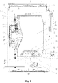
Fig. 1 is a sectional view of a drum washing machine in an embodiment of the present invention (implementation mode I); -
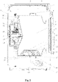
Fig. 2 is a sectional view of a drum washing machine in an embodiment of the present invention (implementation mode II). - A drum washing machine disclosed by the present invention is described in detail in combination with accompanying drawings:
As shown inFigs. 1-2 , the embodiment provides a drum washing machine with a loading port in front side and a non-hole inner drum, which is simple in structure. Washing/rinsing water does not flow between the inner drum and the outer drum so that the washing water consumption of the washing machine is greatly reduced. The possibility of dirt adhesion between the inner drum and the outer drum is avoided. The user's health and experience are greatly improved, and water resources are greatly saved. - The drum washing machine of this embodiment is provided with a
housing 1, and thehousing 1 comprises anupper worktop 3, a front panel, a rear plate, and a bottom plate. Legs are fixedly mounted on the bottom plate and used for supporting the whole washing machine. Adrum 8 in thehousing 1 rotates, and is preferably provided with a liftingrib 11 which continuously lifts and drops to beat the laundry, so that the laundry are cleaned conveniently. Thedrum 8 is of a non-hole structure, and adrum shaft 20 connected with thedrum 8 in a fastened mode passes through abearing 19 as shown and is connected with a driving motor 23. An openable/closeable drum door 9 is mounted on a drum opening at the front portion of thedrum 8, and therefore thedrum 8 is implemented to be of a sealed cabin structure. - An openable/
closeable machine door 7 is mounted on thehousing 1. - Further, in order to achieve water drainage of the non-hole drum, the drum washing machine of this embodiment comprises:
- a
drum 8, provided with a washing chamber capable of containing washing water; - a
drum drainage port 16, arranged on thedrum 8; - a drainage sealing device, arranged on the
drum drainage port 16 to control the opening and closing of the drum drainage port; and - a
water collecting device 6, provided with a water collecting chamber for collecting washing water drained from thedrum drainage port 16. - According to the drum washing machine of this embodiment, according to the structural characteristics of the non-hole drum, dewatering holes are not formed in the drum wall of the drum any more, and only the
drum drainage port 16 is arranged. Thewater collecting device 6 is arranged to collect water drained from thedrum drainage port 16, washing water in thedrum 8 is drained and collected, then the washing water is drained by thewater collecting device 6. An outer drum arranged outside an existing inner drum can be omitted, the possibility of hiding dirt between the inner drum and the outer drum is fundamentally eliminated, and water is also saved. Besides, for a washing machine with a housing of the same size and specification, since the outer drum is not arranged, the volume of the inner drum can be appropriately increased to wash more laundry and achieve the purpose of capacity expansion. - The drainage sealing device provided by the embodiment comprises:
- a
centrifugal piece 12, used for centrifugally moving under the action of centrifugal force; and - a sealing column-
plug 15, used for plugging thedrum drainage port 16; - the centrifugal movement of the
centrifugal piece 12 drives the sealing column-plug 15 to move to open thedrum drainage port 16. - Preferably, the drainage sealing device is arranged in the lifting
rib 11, the liftingrib 11 is provided with a plurality of spray holes 10 for allowing washing water to flow , and the liftingrib 11 is provided with a column-plug through hole for allowing the sealing column-plug 15 to penetrate out of the containing chamber. - The sealing column-
plug 15 of this embodiment comprises a sealing column and a sealing plug. The sealing column is sleeved with anelastic piece 13 for the restoring of the sealing plug by elastic force, and theelastic piece 13 is a spring. - A control method for the drum washing machine in this embodiment comprises: during the washing process of the washing machine, the
centrifugal piece 12 is subjected to centrifugal force to generate centrifugal movement to drive the sealing column-plug 15 to open thedrum drainage port 16 to drain water in the drum by controlling the rotating speed of the drum to reach or exceed a set rotating speed N0. - As an implementation mode of this embodiment, after the washing machine executes a washing procedure or a procedure program, the rotating speed of the drum is controlled to reach a first rotating speed N1 and is maintained for a set time t1, wherein N1 is greater than or equal to N0, and N0 is greater than the rotating speed of the drum in the washing procedure or the rinsing procedure; when the rotating time of the drum kept at the rotating speed N1 reaches t1, the drum is controlled to stop rotating and enter the next procedure.
- Further, the washing machine executes a dewatering procedure, and the lowest dewatering rotating speed N2 in the dewatering procedure is greater than or equal to N0.
- According to the drainage process of the
drum 8, thedrum 8 needs to rotate at a high speed to achieve centrifugal drainage. In order to collect water drained from thedrum drainage port 16, thewater collecting device 6 of this embodiment comprises an annular body, the annular body is located outside the periphery of thedrum 8 and is coaxial with thedrum 8, and an annularwater collecting chamber 28 is arranged inside the annular body. Thedrum drainage port 16 is communicated with the annularwater collecting chamber 28. - The
water collecting device 6 of this embodiment is provided with the annularwater collecting chamber 28, so that no matter what position thedrum 8 is, water drained from thedrum drainage port 16 can be drained into the annularwater collecting chamber 28 to be collected. - In order to drain water drained from the
drum drainage port 16 into the annularwater collecting chamber 28, as shown inFig. 1 , the annular body of this embodiment is provided with anannular opening 27 communicating with the annular water collecting chamber. The drum wall of thedrum 8 is provided with adrainage channel 14, one end of thedrainage channel 14 is communicated with thedrum drainage port 16, and the other end of thedrainage channel 14 is inserted into the annularwater collecting chamber 28 through theannular opening 27. Preferably, thedrainage channel 14 is arranged on the inner side wall of thedrum 8 or the outer side wall of thedrum 8. - According to this embodiment, the
drainage channel 14 used for guiding the water drained from thedrum drainage port 16 into the water collecting device is arranged on the drum wall of the drum, so that the water centrifugally drained from the drum can be better collected into the annularwater collecting chamber 28 of the water collecting device. - Specifically, the annular body of this embodiment comprises an annular side wall, an annular front end wall and an annular rear end wall. The annular side wall surrounds the peripheral wall of the drum by one circle; one end of the annular front end wall is connected to the end of the annular side wall close to a drum opening of the drum, and the other end of the annular front end wall extends toward the drum in the radial direction of the drum. One end of the annular rear end wall is connected to the end of the annular side wall close to the drum bottom side of the drum, and the other end of the annular rear end wall extends toward the drum in the radial direction of the drum.
- The side wall of the drum is provided with a drum drainage port in an area between the drum opening of the drum and the annular body and/or an area between the drum bottom and the annular body, and the annular front end wall and/or the annular rear end wall are/is spaced from the peripheral wall of the drum to form an
annular opening 27. - Preferably, the side wall of the
drum 8 is provided with a drum drainage port in an area between the drum opening and the annular body, and the annular front end wall is spaced from the peripheral wall of the drum to form an annular opening. The annular rear end wall and the peripheral wall of the drum are rotationally and hermetically connected. In this way, water drained into the water collecting device from thedrainage channel 14 can be thrown out of the water collecting device. - Further, as an implementation mode of this embodiment, the annular body comprises an annular outer side wall, an annular inner side wall, an annular front end wall and an annular rear end wall. The annular outer side wall and the annular inner side wall surround the peripheral wall of the drum by one circle respectively, and the annular outer side wall is located on the periphery of the annular inner side wall. One end of the annular front end wall is connected to the end of the annular outer side wall close to the drum opening side of the drum, and the other end of the annular front end wall is connected to the end of the annular inner side wall close to the drum opening side of the drum. One end of the annular rear end wall is connected to the end of the annular outer side wall close to the drum bottom side of the drum, and the other end of the annular rear end wall is connected to the end of the annular inner side wall close to the drum bottom side of the drum.
- The side wall of the drum is provided with a drum drainage port in an area between the drum opening and the annular body and/or an area between the drum bottom and the annular body, and the annular opening is formed in the annular front end wall and/or the annular rear end wall.
- An annular sealed chamber only provided with an
annular opening 27 is formed in the water collecting device of this embodiment, so that water drained into the water collecting device from thedrainage channel 14 is prevented from being thrown out. - In order to drain water drained from the
drum drainage port 16 into the annularwater collecting chamber 28, as shown inFig. 2 , as another implementation mode of this embodiment, a plurality ofdrum drainage ports 16 are arranged on the peripheral wall of thedrum 8, and all thedrum drainage ports 16 are located on or substantially on the same circumference. The side of the annular body close to thedrum 8 is provided with anannular opening 27 communicating with the annularwater collecting chamber 28, and theannular opening 27 surrounds all the drum drainage ports. - Specifically, the annular body of this embodiment comprises an annular side wall, an annular front end wall and an annular rear end wall. The annular side wall surrounds the peripheral wall of the drum by one circle. One end of the annular front end wall is connected to the end of the annular side wall close to a drum opening of the drum, and the other end of the annular front end wall extends toward the drum in the radial direction of the drum. One end of the annular rear end wall is connected to the end of the annular side wall close to the drum bottom side of the drum, and the other end of the annular rear end wall extends toward the drum in the radial direction of the drum.
- The space between the end of the annular front end wall close to the drum and the end of the annular rear end wall close to the drum is set to form an
annular opening 27. - In order to prevent water drained into the water collecting device from splashing out, the annular front end wall and the annular rear end wall of this embodiment are rotationally and hermetically connected with the peripheral wall of the drum.
- In order to drain water collected in the water collecting device, a drainage port is formed in the annular body of the water collecting device. The drainage port is connected with a
drainage pipeline 17, adrainage control device 18 for controlling to be communicated with or blocked from thedrainage pipeline 17 is arranged on thedrainage pipeline 17, and the drainage control device is a drainage valve or a drainage pump. - Further, the drum washing machine of this embodiment further comprises a mounting
disc 26 which shares the same central axis with the drum, and the mountingdisc 26 is arranged at the outer wall of the drum bottom of thedrum 8. - Preferably, the drum washing machine further comprises a driving motor 23, and the driving motor 23 is mounted on the mounting
disc 26. - Preferably, the
water collecting device 6 is fixed on the mountingdisc 26 through a connecting piece, or thewater collecting device 6 and the mountingdisc 26 are integrally formed. - The drum washing machine of this embodiment further comprises a water
inlet pipe support 24, one end of the waterinlet pipe support 24 is mounted on the mountingdisc 26, and the other end of the waterinlet pipe support 24 supports awater inlet pipe 25. - In order to realize inflow of water into the non-hole drum of this embodiment, the drum washing machine of this embodiment comprises a driving motor 23 and a
drum shaft 20, and the driving motor 23 is in transmission connection with thedrum 8 through thedrum shaft 20 to drive thedrum 8 to rotate. Ahollow channel 21 communicating with the interior of thedrum 8 is arranged inside thedrum shaft 20, and a water inlet pipeline of the washing machine is communicated with thehollow channel 21 of thedrum shaft 20. - Specifically, the
drum shaft 20 is connected with the driving motor 23. The driving motor 23 comprises a stator and a rotor, and the rotor is fixedly connected with thedrum shaft 20. A through hole is formed in the centre of the rotor, and the water inlet pipeline passes through the through hole of the rotor and is communicated with thehollow channel 21 of thedrum shaft 20. - Further, a first
dynamic sealing structure 22 is arranged between the water inlet pipeline and the through hole of the rotor, and a second sealing structure is arranged between the through hole of the rotor and thehollow channel 21 of thedrum shaft 20. - According to this embodiment, the problem of how to accurately determine the inlet water amount of the drum washing machine with the non-hole drum is solved at the same time, and the specific solution is as follows.
- A drum washing machine comprises a
drum 8 and awater inlet pipeline 25 communicating with thedrum 8, thedrum 8 is a non-hole drum and is used for containing washing water in washing laundry. Aflow sensor 1 used for detecting the inlet water flow is arranged on thewater inlet pipeline 25. - According to this embodiment, the flow sensor is arranged on the
water inlet pipeline 25 to monitor the inlet water flow. When the set inlet water amount is reached, awater inlet valve 2 is closed, and water inflow is completed. According to this embodiment, the flow sensor is adopted to realize the water inflow of the drum washing machine with the non-hole drum according to the set water level, the washing effect is ensured, the structure is simple, and it is convenient to be controlled. - Further, the drum washing machine of this embodiment comprises a
water inlet valve 2 and adetergent drawer 4. The water inlet pipeline comprises a first water inlet pipe and a second water inlet pipe. An outlet end of thewater inlet valve 2 is communicated with adetergent drawer 4 through the first water inlet pipe, an outlet end of thedetergent drawer 4 is communicated with thedrum 8 through the second water inlet pipe, and the flow sensor is arranged on the first water inlet pipe or the second water inlet pipe. - As an implementation mode of this embodiment, the flow sensor is a rotor flow sensor, a turbine flow sensor, an ultrasonic flow sensor, an electromagnetic flow sensor, or an orifice plate flow sensor.
- This embodiment also solves the problem of the unbalanced air pressure of the sealed cabin of the drum washing machine with the non-hole drum. Specifically, the washing water in the sealed drum is sucked back to a tap water pipe network due to the fact that negative pressure is formed because of the water cut-off of an electromagnetic valve, especially the water cut-off of the tap water pipe network; or water inflow is difficult due to gas being inside the sealed drum.
- The drum washing machine of this embodiment comprises a
drum 8 which is a non-hole drum and is used for containing washing water in washing laundry. And the drum washing machine further comprises an air pressure balancing mechanism which is used for enabling thedrum 8 to be communicated with the external environment so as to balance the air pressure between the drum and the external environment. - During water inflow, air in the sealed chamber of the drum is pressed and can overflow through the balancing mechanism to balance air pressure.
- When water is suddenly cut off, external atmosphere can quickly enter the sealed chamber of the drum and destroy suck-back to balance air pressure, and washing water is prevented from being sucked into the tap water pipe network.
- During dewatering or other processes, the air pressure balancing mechanism can also balance the air pressure of the drum.
- As an implementation mode of this embodiment, the air pressure balancing mechanism comprises a pressure-equalizing hole channel arranged on the
drum 8, and one end of the pressure-equalizing hole channel communicating with the interior of thedrum 8 is arranged at the position, close to a rotating center shaft, of thedrum 8 and is higher than the highest water level in thedrum 8. - Specifically, the pressure-equalizing hole channel is formed in the
drum shaft 20 and enables the interior of thedrum 8 to be communicated with the external environment, and the highest water level in thedrum 8 is lower than thedrum shaft 20. Therefore, water in the drum can be prevented from flowing out of the pressure-equalizing hole channel. - The pressure-equalizing hole channel of this embodiment comprises a first hole channel section and a second hole channel section. The first hole channel section is parallel to the hollow channel, one end of the first hole channel section is communicated with the interior of the drum, one end of the second hole channel section is communicated with the first hole channel section, and the other end of the second hole channel section extends to the periphery wall of the drum shaft to be communicated with the interior of the outer drum. Preferably, the second hole channel section is perpendicular to the first hole channel section to form an L-shaped pressure-equalizing hole channel.
- The above embodiments are only the preferred embodiments of the present invention and do not limit the present invention in any form. Although the present invention has been disclosed in the preferred embodiments as above, the embodiments are not intended to limit the present invention. Any technician familiar with this patent can make slight changes to the technical content suggested above or modify the technical content suggested above into equivalent embodiments with equivalent changes without departing from the scope of the technical solution of the present invention. However, for any content that does not deviate from the technical solution of the present invention, any simple modifications, equivalent changes and modifications made to the above embodiments still fall within the scope of the solution of the present invention.
Claims (10)
- A drum washing machine, comprising:a drum, provided with a washing chamber capable of independently containing washing water;a drum drainage port, arranged on the drum;a drainage sealing device, mounted on the drum drainage port to control opening and closing of the drum drainage port; anda water collecting device, provided with a water collecting chamber for collecting washing water drained from the drum drainage port.
- The drum washing machine according to claim 1, wherein the water collecting device comprises an annular body, the annular body is located around the periphery of the drum and is coaxial with the drum, an annular water collecting chamber is arranged inside the annular body, and the drum drainage port is communicated with the annular water collecting chamber.
- The drum washing machine according to claim 2, wherein the annular body is provided with an annular opening communicating with the annular water collecting chamber, a drainage channel is arranged on a wall of the drum, one end of the drainage channel is communicated with the drum drainage port, and another end of the drainage channel is inserted into the annular water collecting chamber through the annular opening;
preferably, the drainage channel is arranged on an inner sidewall of the drum or an outer sidewall of the drum. - The drum washing machine according to claim 3, wherein the annular body comprises an annular side wall, an annular front end wall and an annular rear end wall, wherein the annular side wall surrounds the peripheral wall of the drum by one circle; one end of the annular front end wall is connected to an end of the annular side wall close to a drum opening of the drum, and another end of the annular front end wall extends toward the drum in a radial direction of the drum;one end of the annular rear end wall is connected to an end of the annular side wall close to a drum bottom of the drum, and another end of the annular rear end wall extends toward the drum in the radial direction of the drum;the wall of the drum is provided with the drum drainage port in an area between the drum opening and the annular body and/or an area between the drum bottom and the annular body, and the annular front end wall and/or the annular rear end wall are/is spaced from the wall of the drum to form an annular opening.
- The drum washing machine according to claim 4, wherein the side wall of the drum is provided with the drum drainage port in the area between the drum opening and the annular body, and the annular front end wall is spaced from the wall of the drum to form the annular opening; the annular rear end wall and the wall of the drum are rotationally and hermetically connected.
- The drum washing machine according to claim 3, wherein the annular body comprises an annular outer side wall, an annular inner side wall, an annular front end wall and an annular rear end wall, wherein the annular outer side wall and the annular inner side wall surround the wall of the drum by one circle respectively, and the annular outer side wall is located on a periphery of the annular inner side wall;one end of the annular front end wall is connected to an end of the annular outer side wall close to a drum opening of the drum, and another end of the annular front end wall is connected to an end of the annular inner side wall close to the drum opening of the drum;one end of the annular rear end wall is connected to an end of the annular outer side wall close to a drum bottom of the drum, and another end of the annular rear end wall is connected to an end of the annular inner side wall close to the drum bottom of the drum;the wall of the drum is provided with the drum drainage port in an area between the drum opening and the annular body and/or an area between the drum bottom and the annular body, and an annular opening is formed in the annular front end wall and/or the annular rear end wall.
- The drum washing machine according to claim 2, wherein a plurality of drum drainage ports are arranged on the wall of the drum, and all the drum drainage ports are located on or substantially on a same circumference; a side of the annular body close to the drum is provided with an annular opening communicating with the annular water collecting chamber, and the annular opening surrounds all the drum drainage ports.
- The drum washing machine according to claim 7, wherein the annular body comprises an annular side wall, an annular front end wall and an annular rear end wall, wherein the annular side wall surrounds the wall of the drum by one circle; one end of the annular front end wall is connected to an end of the annular side wall close to a drum opening of the drum, and another end of the annular front end wall extends toward the drum in a radial direction of the drum;one end of annular rear end wall is connected to an end of the annular side wall close to a drum bottom of the drum, and another end of the annular rear end wall extends toward the drum in a radial direction of the drum;the space between the side of the annular front end wall close to the drum and the side of the annular rear end wall close to the drum is set as open to form an annular opening.
- The drum washing machine according to claim 7, wherein the annular front end wall and the annular rear end wall are rotationally and hermetically connected to the peripheral wall of the drum.
- The drum washing machine according to any one of claim 9, further comprising a mounting disc sharing a same central axis with the drum, wherein the mounting disc is arranged at an outer wall of the drum bottom of the drum;preferably, the drum washing machine further comprises a driving motor mounted on the mounting disc;preferably, the water collecting device is fixed on the mounting disc through a connecting piece, or the water collecting device and the mounting disc are integrally formed.
Applications Claiming Priority (2)
| Application Number | Priority Date | Filing Date | Title |
|---|---|---|---|
| CN201910531445.5A CN112111909B (en) | 2019-06-19 | 2019-06-19 | Drum washing machine |
| PCT/CN2020/095503 WO2020253600A1 (en) | 2019-06-19 | 2020-06-11 | Drum washing machine |
Publications (4)
| Publication Number | Publication Date |
|---|---|
| EP3988706A1 true EP3988706A1 (en) | 2022-04-27 |
| EP3988706A4 EP3988706A4 (en) | 2022-08-24 |
| EP3988706B1 EP3988706B1 (en) | 2024-11-20 |
| EP3988706C0 EP3988706C0 (en) | 2024-11-20 |
Family
ID=73795473
Family Applications (1)
| Application Number | Title | Priority Date | Filing Date |
|---|---|---|---|
| EP20827676.6A Active EP3988706B1 (en) | 2019-06-19 | 2020-06-11 | Drum washing machine |
Country Status (3)
| Country | Link |
|---|---|
| EP (1) | EP3988706B1 (en) |
| CN (1) | CN112111909B (en) |
| WO (1) | WO2020253600A1 (en) |
Cited By (1)
| Publication number | Priority date | Publication date | Assignee | Title |
|---|---|---|---|---|
| US20240117555A1 (en) * | 2022-10-11 | 2024-04-11 | Long Wang YUEN | Washing machine without an external drum field of the invention |
Families Citing this family (2)
| Publication number | Priority date | Publication date | Assignee | Title |
|---|---|---|---|---|
| CN114763658A (en) * | 2021-01-15 | 2022-07-19 | 青岛海尔智能技术研发有限公司 | Clothes treating apparatus |
| CN114855406B (en) * | 2021-01-20 | 2026-03-06 | 青岛海尔滚筒洗衣机有限公司 | A roller assembly and a garment handling device |
Family Cites Families (22)
| Publication number | Priority date | Publication date | Assignee | Title |
|---|---|---|---|---|
| CN2365237Y (en) * | 1999-04-19 | 2000-02-23 | 张佃志 | Few perforated rotary drum of washing machine |
| JP2001300185A (en) * | 2000-04-19 | 2001-10-30 | Sanyo Electric Co Ltd | Washing machine |
| JP2002136792A (en) * | 2000-11-01 | 2002-05-14 | Sanyo Electric Co Ltd | Drum type washing machine |
| KR100763367B1 (en) * | 2000-11-15 | 2007-10-04 | 엘지전자 주식회사 | Drum Washing Machine |
| JP2004105250A (en) * | 2002-09-13 | 2004-04-08 | Toshiba Corp | Drum type washer / dryer |
| KR20040074319A (en) * | 2003-02-17 | 2004-08-25 | 엘지전자 주식회사 | Inner tub of drum washer |
| JP2005177330A (en) * | 2003-12-22 | 2005-07-07 | Mitsubishi Electric Corp | Washing machine |
| CN101982598A (en) * | 2010-09-09 | 2011-03-02 | 任文涛 | Single drum washing machine with dehydration holes capable of automatically opening and closing |
| JP2013128534A (en) * | 2011-12-20 | 2013-07-04 | Panasonic Corp | Drum type washing machine |
| KR101555758B1 (en) * | 2013-12-20 | 2015-09-25 | 동부대우전자 주식회사 | Washing machine |
| JP2015139600A (en) * | 2014-01-29 | 2015-08-03 | ハイアールアジア株式会社 | Parts and washing machine |
| KR102320981B1 (en) * | 2015-04-21 | 2021-11-04 | 엘지전자 주식회사 | Washing machine |
| CN106637792A (en) * | 2016-10-25 | 2017-05-10 | 无锡小天鹅股份有限公司 | Washing machine |
| CN108729125B (en) * | 2017-04-24 | 2020-09-25 | 青岛胶南海尔洗衣机有限公司 | a washing machine |
| CN108797022B (en) * | 2017-04-28 | 2022-08-30 | 青岛海尔洗衣机有限公司 | Drainage structure and drainage method of washing machine |
| CN108797026B (en) * | 2017-04-28 | 2022-03-18 | 青岛海尔洗衣机有限公司 | Washing machine |
| CN108866916B (en) * | 2017-05-09 | 2022-02-01 | 青岛海尔洗涤电器有限公司 | Drum washing machine |
| CN109385797B (en) * | 2017-08-04 | 2025-06-24 | 青岛海尔洗衣机有限公司 | A washing machine |
| CN109423801B (en) * | 2017-08-31 | 2022-04-22 | 青岛海尔洗衣机有限公司 | Washing machine |
| CN208151692U (en) * | 2018-02-27 | 2018-11-27 | 青岛海尔洗衣机有限公司 | A kind of washing tube and the washing machine with the washing tube |
| CN208562861U (en) * | 2018-03-07 | 2019-03-01 | 青岛海尔洗衣机有限公司 | Washing machine |
| CN111945362A (en) * | 2019-05-14 | 2020-11-17 | 青岛海尔滚筒洗衣机有限公司 | Washing machine |
-
2019
- 2019-06-19 CN CN201910531445.5A patent/CN112111909B/en active Active
-
2020
- 2020-06-11 EP EP20827676.6A patent/EP3988706B1/en active Active
- 2020-06-11 WO PCT/CN2020/095503 patent/WO2020253600A1/en not_active Ceased
Cited By (3)
| Publication number | Priority date | Publication date | Assignee | Title |
|---|---|---|---|---|
| US20240117555A1 (en) * | 2022-10-11 | 2024-04-11 | Long Wang YUEN | Washing machine without an external drum field of the invention |
| EP4353893A1 (en) * | 2022-10-11 | 2024-04-17 | Yuen, Long Wang | A washing machine without an external drum |
| US12351969B2 (en) * | 2022-10-11 | 2025-07-08 | Long Wang YUEN | Washing machine without an external drum |
Also Published As
| Publication number | Publication date |
|---|---|
| WO2020253600A1 (en) | 2020-12-24 |
| CN112111909B (en) | 2022-09-23 |
| EP3988706A4 (en) | 2022-08-24 |
| CN112111909A (en) | 2020-12-22 |
| EP3988706B1 (en) | 2024-11-20 |
| EP3988706C0 (en) | 2024-11-20 |
Similar Documents
| Publication | Publication Date | Title |
|---|---|---|
| US11220771B2 (en) | Drum washing machine | |
| EP3988701B1 (en) | Drum washing machine and control method therefor | |
| EP3988706B1 (en) | Drum washing machine | |
| EP3971337B1 (en) | Washing machine | |
| EP3733950A1 (en) | Washing equipment and washing water outlet method | |
| EP3978676A1 (en) | Laundry lifting device for washing machine, and drum washing machine | |
| WO2021139518A1 (en) | Laundry lifting device for washing machine, and drum washing machine | |
| CN111764115B (en) | Sealing drainage device of drum washing machine, drum washing machine and control method | |
| CN108796972A (en) | A kind of washing machine | |
| CN110273250A (en) | Washing machine | |
| CN108796971A (en) | A kind of washing machine | |
| WO2021139519A1 (en) | Laundry lifting device for washing machine, and drum washing machine | |
| WO2020182210A1 (en) | Sealed drainage device of drum washing machine and drum washing machine | |
| CN111691128B (en) | A drum washing machine | |
| CN111691115B (en) | Sealing drainage device of drum washing machine and drum washing machine | |
| JP2022542636A (en) | washing machine | |
| WO2021139520A1 (en) | Clothes lifting apparatus for use in washing machine and drum washing machine | |
| CN111850925B (en) | Drum washing machine | |
| CN108796963B (en) | Washing machine | |
| WO2021184960A1 (en) | Washing machine | |
| CN111691147B (en) | A drum washing machine | |
| CN111058236A (en) | Drum washing machine | |
| CN111945390A (en) | a washing machine | |
| CN115506122B (en) | Inner barrel assembly of washing machine and washing machine | |
| CN112779728B (en) | Clothes lifting device for washing machine and drum washing machine |
Legal Events
| Date | Code | Title | Description |
|---|---|---|---|
| STAA | Information on the status of an ep patent application or granted ep patent |
Free format text: STATUS: THE INTERNATIONAL PUBLICATION HAS BEEN MADE |
|
| PUAI | Public reference made under article 153(3) epc to a published international application that has entered the european phase |
Free format text: ORIGINAL CODE: 0009012 |
|
| STAA | Information on the status of an ep patent application or granted ep patent |
Free format text: STATUS: REQUEST FOR EXAMINATION WAS MADE |
|
| 17P | Request for examination filed |
Effective date: 20220114 |
|
| AK | Designated contracting states |
Kind code of ref document: A1 Designated state(s): AL AT BE BG CH CY CZ DE DK EE ES FI FR GB GR HR HU IE IS IT LI LT LU LV MC MK MT NL NO PL PT RO RS SE SI SK SM TR |
|
| A4 | Supplementary search report drawn up and despatched |
Effective date: 20220721 |
|
| RIC1 | Information provided on ipc code assigned before grant |
Ipc: D06F 37/06 20060101ALN20220715BHEP Ipc: D06F 23/02 20060101ALN20220715BHEP Ipc: D06F 37/04 20060101ALI20220715BHEP Ipc: D06F 39/08 20060101AFI20220715BHEP |
|
| DAV | Request for validation of the european patent (deleted) | ||
| DAX | Request for extension of the european patent (deleted) | ||
| STAA | Information on the status of an ep patent application or granted ep patent |
Free format text: STATUS: EXAMINATION IS IN PROGRESS |
|
| RIC1 | Information provided on ipc code assigned before grant |
Ipc: D06F 37/06 20060101ALN20231128BHEP Ipc: D06F 23/02 20060101ALN20231128BHEP Ipc: D06F 37/04 20060101ALI20231128BHEP Ipc: D06F 39/08 20060101AFI20231128BHEP |
|
| 17Q | First examination report despatched |
Effective date: 20231221 |
|
| GRAP | Despatch of communication of intention to grant a patent |
Free format text: ORIGINAL CODE: EPIDOSNIGR1 |
|
| STAA | Information on the status of an ep patent application or granted ep patent |
Free format text: STATUS: GRANT OF PATENT IS INTENDED |
|
| RIC1 | Information provided on ipc code assigned before grant |
Ipc: D06F 37/06 20060101ALN20240627BHEP Ipc: D06F 23/02 20060101ALN20240627BHEP Ipc: D06F 37/04 20060101ALI20240627BHEP Ipc: D06F 39/08 20060101AFI20240627BHEP |
|
| INTG | Intention to grant announced |
Effective date: 20240716 |
|
| GRAS | Grant fee paid |
Free format text: ORIGINAL CODE: EPIDOSNIGR3 |
|
| GRAA | (expected) grant |
Free format text: ORIGINAL CODE: 0009210 |
|
| STAA | Information on the status of an ep patent application or granted ep patent |
Free format text: STATUS: THE PATENT HAS BEEN GRANTED |
|
| AK | Designated contracting states |
Kind code of ref document: B1 Designated state(s): AL AT BE BG CH CY CZ DE DK EE ES FI FR GB GR HR HU IE IS IT LI LT LU LV MC MK MT NL NO PL PT RO RS SE SI SK SM TR |
|
| REG | Reference to a national code |
Ref country code: GB Ref legal event code: FG4D |
|
| REG | Reference to a national code |
Ref country code: CH Ref legal event code: EP |
|
| REG | Reference to a national code |
Ref country code: DE Ref legal event code: R096 Ref document number: 602020041783 Country of ref document: DE |
|
| REG | Reference to a national code |
Ref country code: IE Ref legal event code: FG4D |
|
| U01 | Request for unitary effect filed |
Effective date: 20241216 |
|
| U07 | Unitary effect registered |
Designated state(s): AT BE BG DE DK EE FI FR IT LT LU LV MT NL PT RO SE SI Effective date: 20250102 |
|
| PG25 | Lapsed in a contracting state [announced via postgrant information from national office to epo] |
Ref country code: IS Free format text: LAPSE BECAUSE OF FAILURE TO SUBMIT A TRANSLATION OF THE DESCRIPTION OR TO PAY THE FEE WITHIN THE PRESCRIBED TIME-LIMIT Effective date: 20250320 Ref country code: HR Free format text: LAPSE BECAUSE OF FAILURE TO SUBMIT A TRANSLATION OF THE DESCRIPTION OR TO PAY THE FEE WITHIN THE PRESCRIBED TIME-LIMIT Effective date: 20241120 |
|
| PG25 | Lapsed in a contracting state [announced via postgrant information from national office to epo] |
Ref country code: ES Free format text: LAPSE BECAUSE OF FAILURE TO SUBMIT A TRANSLATION OF THE DESCRIPTION OR TO PAY THE FEE WITHIN THE PRESCRIBED TIME-LIMIT Effective date: 20241120 |
|
| PG25 | Lapsed in a contracting state [announced via postgrant information from national office to epo] |
Ref country code: NO Free format text: LAPSE BECAUSE OF FAILURE TO SUBMIT A TRANSLATION OF THE DESCRIPTION OR TO PAY THE FEE WITHIN THE PRESCRIBED TIME-LIMIT Effective date: 20250220 |
|
| PG25 | Lapsed in a contracting state [announced via postgrant information from national office to epo] |
Ref country code: GR Free format text: LAPSE BECAUSE OF FAILURE TO SUBMIT A TRANSLATION OF THE DESCRIPTION OR TO PAY THE FEE WITHIN THE PRESCRIBED TIME-LIMIT Effective date: 20250221 |
|
| PG25 | Lapsed in a contracting state [announced via postgrant information from national office to epo] |
Ref country code: PL Free format text: LAPSE BECAUSE OF FAILURE TO SUBMIT A TRANSLATION OF THE DESCRIPTION OR TO PAY THE FEE WITHIN THE PRESCRIBED TIME-LIMIT Effective date: 20241120 |
|
| PG25 | Lapsed in a contracting state [announced via postgrant information from national office to epo] |
Ref country code: RS Free format text: LAPSE BECAUSE OF FAILURE TO SUBMIT A TRANSLATION OF THE DESCRIPTION OR TO PAY THE FEE WITHIN THE PRESCRIBED TIME-LIMIT Effective date: 20250220 |
|
| PG25 | Lapsed in a contracting state [announced via postgrant information from national office to epo] |
Ref country code: SM Free format text: LAPSE BECAUSE OF FAILURE TO SUBMIT A TRANSLATION OF THE DESCRIPTION OR TO PAY THE FEE WITHIN THE PRESCRIBED TIME-LIMIT Effective date: 20241120 |
|
| PG25 | Lapsed in a contracting state [announced via postgrant information from national office to epo] |
Ref country code: SK Free format text: LAPSE BECAUSE OF FAILURE TO SUBMIT A TRANSLATION OF THE DESCRIPTION OR TO PAY THE FEE WITHIN THE PRESCRIBED TIME-LIMIT Effective date: 20241120 |
|
| PG25 | Lapsed in a contracting state [announced via postgrant information from national office to epo] |
Ref country code: CZ Free format text: LAPSE BECAUSE OF FAILURE TO SUBMIT A TRANSLATION OF THE DESCRIPTION OR TO PAY THE FEE WITHIN THE PRESCRIBED TIME-LIMIT Effective date: 20241120 |
|
| U20 | Renewal fee for the european patent with unitary effect paid |
Year of fee payment: 6 Effective date: 20250627 |
|
| PLBE | No opposition filed within time limit |
Free format text: ORIGINAL CODE: 0009261 |
|
| STAA | Information on the status of an ep patent application or granted ep patent |
Free format text: STATUS: NO OPPOSITION FILED WITHIN TIME LIMIT |
|
| 26N | No opposition filed |
Effective date: 20250821 |
|
| REG | Reference to a national code |
Ref country code: CH Ref legal event code: H13 Free format text: ST27 STATUS EVENT CODE: U-0-0-H10-H13 (AS PROVIDED BY THE NATIONAL OFFICE) Effective date: 20260127 |
|
| PG25 | Lapsed in a contracting state [announced via postgrant information from national office to epo] |
Ref country code: MC Free format text: LAPSE BECAUSE OF FAILURE TO SUBMIT A TRANSLATION OF THE DESCRIPTION OR TO PAY THE FEE WITHIN THE PRESCRIBED TIME-LIMIT Effective date: 20241120 |
|
| GBPC | Gb: european patent ceased through non-payment of renewal fee |
Effective date: 20250611 |
|
| PG25 | Lapsed in a contracting state [announced via postgrant information from national office to epo] |
Ref country code: GB Free format text: LAPSE BECAUSE OF NON-PAYMENT OF DUE FEES Effective date: 20250611 |
|
| PG25 | Lapsed in a contracting state [announced via postgrant information from national office to epo] |
Ref country code: IE Free format text: LAPSE BECAUSE OF NON-PAYMENT OF DUE FEES Effective date: 20250611 |
|
| PG25 | Lapsed in a contracting state [announced via postgrant information from national office to epo] |
Ref country code: CH Free format text: LAPSE BECAUSE OF NON-PAYMENT OF DUE FEES Effective date: 20250630 |