EP3988333A1 - Pneumatic tire - Google Patents
Pneumatic tire Download PDFInfo
- Publication number
- EP3988333A1 EP3988333A1 EP21202480.6A EP21202480A EP3988333A1 EP 3988333 A1 EP3988333 A1 EP 3988333A1 EP 21202480 A EP21202480 A EP 21202480A EP 3988333 A1 EP3988333 A1 EP 3988333A1
- Authority
- EP
- European Patent Office
- Prior art keywords
- tire
- rubber layer
- hardness
- pneumatic tire
- radial direction
- Prior art date
- Legal status (The legal status is an assumption and is not a legal conclusion. Google has not performed a legal analysis and makes no representation as to the accuracy of the status listed.)
- Granted
Links
Images
Classifications
-
- B—PERFORMING OPERATIONS; TRANSPORTING
- B60—VEHICLES IN GENERAL
- B60C—VEHICLE TYRES; TYRE INFLATION; TYRE CHANGING; CONNECTING VALVES TO INFLATABLE ELASTIC BODIES IN GENERAL; DEVICES OR ARRANGEMENTS RELATED TO TYRES
- B60C11/00—Tyre tread bands; Tread patterns; Anti-skid inserts
- B60C11/0041—Tyre tread bands; Tread patterns; Anti-skid inserts comprising different tread rubber layers
-
- B—PERFORMING OPERATIONS; TRANSPORTING
- B60—VEHICLES IN GENERAL
- B60C—VEHICLE TYRES; TYRE INFLATION; TYRE CHANGING; CONNECTING VALVES TO INFLATABLE ELASTIC BODIES IN GENERAL; DEVICES OR ARRANGEMENTS RELATED TO TYRES
- B60C19/00—Tyre parts or constructions not otherwise provided for
- B60C19/002—Noise damping elements provided in the tyre structure or attached thereto, e.g. in the tyre interior
-
- B—PERFORMING OPERATIONS; TRANSPORTING
- B60—VEHICLES IN GENERAL
- B60C—VEHICLE TYRES; TYRE INFLATION; TYRE CHANGING; CONNECTING VALVES TO INFLATABLE ELASTIC BODIES IN GENERAL; DEVICES OR ARRANGEMENTS RELATED TO TYRES
- B60C19/00—Tyre parts or constructions not otherwise provided for
- B60C19/12—Puncture preventing arrangements
- B60C19/122—Puncture preventing arrangements disposed inside of the inner liner
-
- B—PERFORMING OPERATIONS; TRANSPORTING
- B60—VEHICLES IN GENERAL
- B60C—VEHICLE TYRES; TYRE INFLATION; TYRE CHANGING; CONNECTING VALVES TO INFLATABLE ELASTIC BODIES IN GENERAL; DEVICES OR ARRANGEMENTS RELATED TO TYRES
- B60C9/00—Reinforcements or ply arrangement of pneumatic tyres
- B60C2009/0071—Reinforcements or ply arrangement of pneumatic tyres characterised by special physical properties of the reinforcements
-
- B—PERFORMING OPERATIONS; TRANSPORTING
- B60—VEHICLES IN GENERAL
- B60C—VEHICLE TYRES; TYRE INFLATION; TYRE CHANGING; CONNECTING VALVES TO INFLATABLE ELASTIC BODIES IN GENERAL; DEVICES OR ARRANGEMENTS RELATED TO TYRES
- B60C11/00—Tyre tread bands; Tread patterns; Anti-skid inserts
- B60C11/0008—Tyre tread bands; Tread patterns; Anti-skid inserts characterised by the tread rubber
- B60C2011/0016—Physical properties or dimensions
- B60C2011/0025—Modulus or tan delta
-
- B—PERFORMING OPERATIONS; TRANSPORTING
- B60—VEHICLES IN GENERAL
- B60C—VEHICLE TYRES; TYRE INFLATION; TYRE CHANGING; CONNECTING VALVES TO INFLATABLE ELASTIC BODIES IN GENERAL; DEVICES OR ARRANGEMENTS RELATED TO TYRES
- B60C11/00—Tyre tread bands; Tread patterns; Anti-skid inserts
- B60C11/0008—Tyre tread bands; Tread patterns; Anti-skid inserts characterised by the tread rubber
- B60C2011/0016—Physical properties or dimensions
- B60C2011/0033—Thickness of the tread
Definitions
- the present invention relates to a pneumatic tire.
- the present invention has been made in view of the above circumstances, and a main object of the present invention is to provide a pneumatic tire that can have enhanced durability of the tire and a sound damper while maintaining a sufficient sound-damping effect.
- the present invention is directed to a pneumatic tire including: a pair of bead cores; a carcass layer including a carcass ply extending on and between the pair of bead cores through a tread portion and a pair of sidewall portions; a belt layer disposed outward of the carcass layer in a tire radial direction; a tread rubber disposed outward of the belt layer in the tire radial direction; an inner liner rubber layer disposed on a tire inner cavity side of the carcass layer; and a porous sound damper disposed on the tire inner cavity side of the inner liner rubber layer at the tread portion, wherein in a normal state where the pneumatic tire is fitted on a normal rim and inflated to a normal internal pressure and no load is applied to the pneumatic tire, a length W1 in a tire axial direction of the sound damper is smaller than a distance H in the tire radial direction from a bead base line to a maximum width position in an inner cavity surface of the sidewall portion, in a region
- the length W1 in the tire axial direction of the sound damper is preferably not greater than 50% of a tread ground-contact width TW.
- the length W1 in the tire axial direction of the sound damper is preferably not greater than 40% of the tread ground-contact width TW.
- a hardness Ho of the rubber layer disposed on an outermost side in the tire radial direction among the rubber layers is preferably not less than 105% of a hardness Hi of the rubber layer disposed on an innermost side in the tire radial direction among the rubber layers.
- the length W1 in the tire axial direction of the sound damper, the tread ground-contact width TW, the hardness Ho of the rubber layer disposed on the outermost side in the tire radial direction among the rubber layers, and the hardness Hi of the rubber layer disposed on the innermost side in the tire radial direction among the rubber layers preferably satisfy a relationship of (W1/TW)/(Ho/Hi) ⁇ 0.5.
- the length W1, the tread ground-contact width TW, the hardness Ho, and the hardness Hi preferably satisfy a relationship of (W1/TW)/(Ho/Hi) ⁇ 0.4.
- the length W1, the tread ground-contact width TW, the hardness Ho, and the hardness Hi preferably satisfy a relationship of (W1/TW)/(Ho/Hi) ⁇ 0.3.
- the length W1 in the tire axial direction of the sound damper is preferably not greater than 150 mm.
- the length W1 is preferably not greater than 100 mm.
- a length HI in the tire radial direction of the sound damper is preferably not greater than 50 mm.
- the length HI is preferably not greater than 30 mm.
- a loss tangent tan ⁇ at 0°C and a loss tangent tan ⁇ at 30°C of the rubber layer disposed on the outermost side in the tire radial direction among the rubber layers preferably satisfy a relationship of 0°C tan ⁇ /30°C tan ⁇ 3.
- the loss tangent tan ⁇ at 0°C and the loss tangent tan ⁇ at 30°C preferably satisfy a relationship of 0°C tan ⁇ /30°C tan ⁇ 2.
- each rubber layer contains a filler component and a plasticizer component, and, as for a ratio of a total amount of the filler component to a total amount of the plasticizer component in each rubber layer, the ratio in the rubber layer located more inward in the tire radial direction is smaller.
- the pneumatic tire according to the present invention further includes a sealant layer for preventing a puncture, on a tire inner cavity surface, and a hardness of the sealant layer is smaller than a hardness of the inner liner rubber layer.
- the hardness of each rubber layer Since, as for the hardness of each rubber layer, the hardness of the rubber layer located more inward in the tire radial direction is smaller in the pneumatic tire according to the present invention, vibration is attenuated toward the inner side in the tire radial direction. Therefore, even with the sound damper having a small length in the tire axial direction, a sufficient sound-damping effect is obtained. Accordingly, while the sound-damping effect is maintained, the length in the tire axial direction of the sound damper can be decreased, so that the durability of the tire and the sound damper can be enhanced.
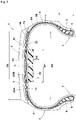
- FIG. 1 is a meridian cross-sectional view including a tire rotation axis (not shown) in a normal state of a pneumatic tire 1 according to the present embodiment.
- the "normal state” is a state where the pneumatic tire 1 is fitted on a normal rim and inflated to a normal internal pressure and no load is applied to the pneumatic tire 1.
- dimensions and the like of components of the pneumatic tire 1 are values measured in the normal state.
- the "normal rim” is a rim that is defined, in a standard system including a standard on which the pneumatic tire 1 is based, by the standard for each tire, and is, for example, the "standard rim” in the JATMA standard, the "Design Rim” in the TRA standard, or the “Measuring Rim” in the ETRTO standard.
- the "normal internal pressure” is an air pressure that is defined, in a standard system including a standard on which the pneumatic tire 1 is based, by the standard for each tire, and is the "maximum air pressure” in the JATMA standard, the maximum value indicated in the table "TIRE LOAD LIMITS AT VARIOUS COLD INFLATION PRESSURES" in the TRA standard, or the "INFLATION PRESSURE” in the ETRTO standard.
- the normal internal pressure may be, for example, 180 kPa.
- the pneumatic tire 1 is suitably used as a radial tire, for a small truck, having a normal internal pressure of 350 to 600 kPa.
- the pneumatic tire 1 includes a pair of bead cores 5, a carcass layer 6, a belt layer 7, and a pair of bead apex rubbers 8.
- the bead cores 5 are disposed at a pair of bead portions 4.
- Each bead core 5 is formed, for example, in a polygonal cross-sectional shape in which a bead wire (not shown) made of steel is wound in multiple rows and multiple stages.
- the carcass layer 6 includes at least one carcass ply.
- the carcass ply is formed by, for example, coating an array of carcass cords with a topping rubber.
- each of the carcass cords for example, steel or an organic fiber such as polyester fiber, nylon fiber, rayon fiber, polyethylene naphthalate fiber, or aramid fiber, is used.
- the carcass layer 6 of the present embodiment includes a carcass ply 6A and a carcass ply 6B.
- the carcass layer 6 includes the topping rubbers of the carcass plies 6A and 6B, and a sheet-shaped rubber in the form in which the sheet-shaped rubber is provided between the carcass plies 6A and 6B.
- the carcass ply 6A is disposed so as to extend on and between the pair of bead cores 5 through a tread portion 2 and a pair of sidewall portions 3.
- the carcass ply 6B is disposed outward of the carcass ply 6A.
- the belt layer 7 is disposed outward of the carcass layer 6 in the tire radial direction.
- the belt layer 7 includes at least one belt ply.
- the belt layer 7 includes two belt plies 7A and 7B on the inner side and the outer side, respectively, in the tire radial direction.
- the belt plies 7A and 7B are each formed by, for example, coating an array of belt cords with a topping rubber.
- the belt cords are arranged in the tire circumferential direction. That is, the belt cords are preferably arranged so as to be inclined, for example, at an angle of 15 to 45° with respect to a tire equator C.
- the belt cords are preferably highly elastic cords such as steel cords.
- Each bead apex rubber 8 is disposed outward of the bead core 5 in the tire radial direction.
- the bead apex rubber 8 is formed in a substantially triangular cross-sectional shape that is tapered toward the outer side in the tire radial direction.
- a band layer 9 may be disposed outward of the belt layer 7 in the tire radial direction.
- the band layer 9 includes at least one band ply in which organic fiber cords are arranged at a small angle, for example, not greater than 10 degrees, with respect to the tire circumferential direction.
- the band ply may be obtained by splicing either a jointless band or ply that is formed by spirally winding a band cord or a ribbon-shaped band-like ply.
- An inner liner rubber layer 10 is formed inward of the carcass layer 6, that is, on a tire inner cavity surface.
- the inner liner rubber layer 10 is formed from an air-impermeable rubber and maintains the internal pressure.
- a tread rubber 2G is disposed outward of the belt layer 7 and the band layer 9 in the tire radial direction.
- the tread rubber 2G of the present embodiment includes a cap rubber layer 2GA disposed on the outermost side in the tire radial direction, and a base rubber layer 2GB disposed inward of the cap rubber layer 2GA in the tire radial direction.
- the tread rubber 2G may be composed of a single rubber layer.
- the pneumatic tire 1 includes a sound damper 20 on the inner side of the tread portion 2 in the tire radial direction.
- the sound damper 20 is disposed on the tire inner cavity side of the inner liner rubber layer 10.
- the sound damper 20 is composed of, for example, a porous sponge material.
- the sponge material is a spongy porous structure, and examples of the sponge material include, in addition to a so-called sponge itself having open cells and obtained by foaming a rubber or synthetic resin, a web-like material in which animal fibers, plant fibers, synthetic fibers, or the like are entwined and integrally connected.
- the "porous structure" includes a structure having not only open cells but also closed cells.
- an open cell sponge material made of polyurethane is used for the sound damper 20 of this example.
- Such a sound damper 20 has a hardness smaller than those of a rubber layer 30 and a sealant layer 40, which will be described later.
- the sponge material as described above reduces sound (cavity resonance energy) by its surface and inner porous portions converting the vibration energy of vibrating air into heat energy to consume the vibration energy, thereby reducing the running noise of the pneumatic tire 1.
- the sponge material is easily deformed, for example, easily contracted and bent, and thus does not substantially affect the deformation of the tire during running. Therefore, deterioration of steering stability can be prevented.
- the sponge material has a very small specific gravity, and thus can prevent deterioration of the weight balance of the tire.
- synthetic resin sponges such as ether-based polyurethane sponges, ester-based polyurethane sponges, and polyethylene sponges
- rubber sponges such as chloroprene rubber sponges (CR sponges), ethylene-propylene rubber sponges (EPDM sponges), and nitrile rubber sponges (NBR sponges)
- CR sponges chloroprene rubber sponges
- EPDM sponges ethylene-propylene rubber sponges
- NBR sponges nitrile rubber sponges
- polyethylene sponges, polyurethane sponges including ether-based polyurethane sponges, or the like are preferable from the viewpoint of sound-damping properties, lightness, foam controllability, durability, etc.
- the sound damper 20 has a long band shape having a bottom surface fixed to the inner cavity surface of the tread portion 2, and extends in the tire circumferential direction.
- the sound damper 20 may be formed in a substantially annular shape by abutting outer end portions in the circumferential direction against each other, or the outer end portions may be separated from each other in the circumferential direction.
- the sound damper 20 has substantially the same cross-sectional shape at each position in the circumferential direction except the outer end portions.
- This cross-sectional shape in order to prevent falling-down or deformation of the tire during running, a flat and horizontally long shape having a small height with respect to the width in the tire axial direction is preferable.
- a length W1 in the tire axial direction of the sound damper 20 (that is, the width of the sound damper 20) is smaller than a distance H in the tire radial direction from a bead base line to a maximum width position in the inner cavity surface of the sidewall portion 3.
- the tread portion 2 includes a plurality of rubber layers 30 laminated in the tire radial direction.
- the "rubber layer” is intended to be a rubber layer that has a larger thickness than the inner liner rubber layer 10 and that includes no cord.
- the rubber layers 30 include the tread rubber 2G (cap rubber layer 2GA and base rubber layer 2GB) and the inner liner rubber layer 10.
- the rubber layers 30 may include an intermediate rubber layer between the carcass plies 6A and 6B, an intermediate rubber layer between the belt plies 7A and 7B, an intermediate rubber layer between the carcass layer 6 and the belt layer 7, an intermediate rubber layer between the belt layer 7 and the band layer 9, and an intermediate rubber layer between the carcass layer 6 and the inner liner rubber layer 10.
- the hardness of the rubber layer 30 located more inward in the tire radial direction is smaller.
- the hardness of the base rubber layer 2GB is smaller than the hardness of the cap rubber layer 2GA.
- the hardness of the inner liner rubber layer 10 is smaller than the hardness of the base rubber layer 2GB. Due to such a configuration, vibration inputted from the tread surface of the tread portion 2 is attenuated toward the inner side in the tire radial direction. Therefore, even with the sound damper 20 having a small length in the tire axial direction, a sufficient sound-damping effect is obtained.
- the sound damper 20 is attached to the inner liner rubber layer 10 by using, for example, an adhesive or the like.
- an adhesive or the like if the hardness difference between the porous sound damper 20 and the inner liner rubber layer 10 is large, when the pneumatic tire 1 is used for a long period of time, stress may be concentrated at the interface between the porous sound damper 20 and the inner liner rubber layer 10, so that the sound damper 20 may be peeled.
- the rubber layer 30 located more inward in the tire radial direction has a smaller hardness, the hardness difference between the sound damper 20 and the inner liner rubber layer 10 is small, so that the resistance to peeling of the sound damper 20 can be improved.
- the length W1 in the tire axial direction of the sound damper 20 is preferably not greater than 50% of a tread ground-contact width TW.
- the tread ground-contact width TW is the distance in the tire axial direction between tread ground-contact edges TE1 and TE2 when the normal load is applied to the tire in the normal state and the tire is brought into contact with a flat surface at a camber angle of 0°. With such a sound damper 20, peeling of the sound damper 20 from the inner cavity surface of the tread portion 2 can be suppressed, so that the durability of the pneumatic tire 1 and the sound damper 20 can be easily enhanced.
- the length W1 in the tire axial direction of the sound damper 20 is more preferably not greater than 40% of the tread ground-contact width TW.
- a hardness Ho of the rubber layer 30 disposed on the outermost side in the tire radial direction (in the present embodiment, the cap rubber layer 2GA) among the rubber layers 30 is preferably not less than 105% of a hardness Hi of the rubber layer 30 disposed on the innermost side in the tire radial direction (in the present embodiment, the inner liner rubber layer 10) among the rubber layers 30.
- the hardness Ho of the rubber layer 30 disposed on the outermost side in the tire radial direction among the rubber layers 30 is preferably less than 200% of the hardness Hi of the rubber layer 30 disposed on the innermost side in the tire radial direction among the rubber layers 30.
- the hardness of each rubber layer 30 can be measured, for example, using a hardness meter having a press needle diameter of 0.5 mm or less. By using such a hardness meter, it is possible to evaluate elasticity that can follow the unevenness of a road surface at the micro level, and a sound-damping effect in actual running can be obtained.
- the length W1 in the tire axial direction of the sound damper 20, the tread ground-contact width TW, and the hardnesses Ho and Hi of the rubber layers 30 preferably satisfy the following relationship. W1/TW / Ho/Hi ⁇ 0.5 In such a pneumatic tire 1, the durability of the pneumatic tire 1 and the sound damper 20 can be enhanced while a sufficient sound-damping effect is maintained.
- the relationship between the length W1 in the tire axial direction of the sound damper 20, the tread ground-contact width TW, and the hardnesses Ho and Hi of the rubber layers is more preferably W1/TW / Ho/Hi ⁇ 0.4 .
- the relationship between the length W1 in the tire axial direction of the sound damper 20, the tread ground-contact width TW, and the hardnesses Ho and Hi of the rubber layers is further preferably W1/TW / Ho/Hi ⁇ 0.3 .
- the length W1 in the tire axial direction of the sound damper 20 is preferably not greater than 70% of a length W2 in the tire axial direction of the belt layer 7. With such a sound damper 20, peeling of the sound damper 20 from the inner cavity surface of the tread portion 2 can be suppressed, so that the durability of the pneumatic tire 1 and the sound damper 20 can be easily enhanced.
- the length W1 in the tire axial direction of the sound damper 20 is preferably not greater than 150 mm. With such a sound damper 20, peeling of the sound damper 20 from the inner cavity surface of the tread portion 2 can be suppressed, so that the durability of the pneumatic tire 1 and the sound damper 20 can be easily enhanced.
- the length W1 in the tire axial direction of the sound damper 20 is more preferably not greater than 120 mm and further preferably not greater than 100 mm.
- a length HI in the tire radial direction of the sound damper 20 is preferably not greater than 50 mm. With such a sound damper 20, peeling of the sound damper 20 from the inner cavity surface of the tread portion 2 can be suppressed, so that the durability of the pneumatic tire 1 and the sound damper 20 can be easily enhanced.
- the length HI in the tire radial direction of the sound damper 20 is more preferably not greater than 30 mm.
- a loss tangent tan ⁇ at 0°C and a loss tangent tan ⁇ at 30°C of the rubber layer 30 disposed on the outermost side in the tire radial direction preferably satisfy the following relationship. 0 ° C tan ⁇ / 30 ° C tan ⁇ ⁇ 3
- the temperature dependence of the sound-damping effect is reduced, and a good sound-damping effect is obtained in a wide temperature range.
- the relationship between the loss tangent tan ⁇ at 0°C and the loss tangent tan ⁇ at 30°C of the rubber layer 30 is more preferably 0 ° C tan ⁇ / 30 ° C tan ⁇ ⁇ 2 .
- the loss tangent tan ⁇ at 0°C and the loss tangent tan ⁇ at 30°C are values measured according to the standards of JIS K 6394 under the conditions of each measurement temperature (0°C or 30°C), a frequency of 10 Hz, an initial elongation strain of 10%, and a dynamic strain amplitude of ⁇ 2% using a viscoelasticity spectrometer manufactured by Iwamoto Seisakusho.
- Each rubber layer 30 contains a filler component.
- the filler component include carbon black and silica.
- the filler component is measured, for example, as ash by thermogravimetric analysis (TGA) of a vulcanized rubber according to JIS K 6226-1: 2003.
- such a total amount in the rubber layer 30 located more inward in the tire radial direction is preferably smaller. Accordingly, vibration is attenuated toward the inner side in the tire radial direction. Therefore, even with the sound damper 20 having a small length in the tire axial direction, a sufficient sound-damping effect is obtained.
- Each rubber layer 30 contains a plasticizer component.
- the plasticizer component include oil.
- the plasticizer component is measured, for example, as an acetone extract according to JIS K 6229: 2015.
- the total amount of the plasticizer component in each rubber layer 30 located more inward in the tire radial direction is preferably larger. Accordingly, vibration is attenuated toward the inner side in the tire radial direction. Therefore, even with the sound damper 20 having a small length in the tire axial direction, a sufficient sound-damping effect is obtained.
- such a ratio in the rubber layer 30 located more inward in the tire radial direction is preferably smaller. Accordingly, vibration is attenuated toward the inner side in the tire radial direction. Therefore, even with the sound damper 20 having a small length in the tire axial direction, a sufficient sound-damping effect is obtained.
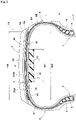
- FIG. 2 shows a pneumatic tire 1A which is a modification of the pneumatic tire 1 in FIG. 1 .
- the configuration of the above-described pneumatic tire 1 can be adopted for the portions that are not described below.
- the pneumatic tire 1A further includes the sealant layer 40 for preventing a puncture, on the tire inner cavity surface.
- the sealant layer 40 is formed on the inner cavity side of the inner liner rubber layer 10.
- the sound damper 20 is formed on the inner cavity side of the sealant layer 40.
- a sealant for forming the sealant layer 40 is not particularly limited, and the sealant of this example contains a rubber component, a liquid polymer, and a crosslinking agent.
- butyl-based rubbers such as isobutylene-isoprene-rubber and halogenated isobutylene-isoprene-rubber are adopted.
- a butyl-based rubber and a diene-based rubber can be mixed and used.
- liquid polymer examples include liquid polybutene, liquid polyisobutene, liquid polyisoprene, liquid polybutadiene, liquid poly- ⁇ -olefin, liquid isobutylene, liquid ethylene- ⁇ -olefin copolymers, liquid ethylene-propylene copolymers, and liquid ethylenebutylene copolymers.
- crosslinking agent a known compound can be used, and an organic peroxide is preferable.
- an organic peroxide is preferable.
- Use of the butyl-based rubber or the liquid polymer in an organic peroxide crosslinking system improves the adhesiveness, the sealing performance, the fluidity, and processability.
- organic peroxide crosslinking agent
- examples of the organic peroxide include: acyl peroxides such as benzoyl peroxide, dibenzoyl peroxide, and p-chlorobenzoyl peroxide; peroxyesters such as 1-butyl peroxyacetate, t-butyl peroxybenzoate, and t-butyl peroxyphthalate; ketone peroxides such as methyl ethyl ketone peroxide; alkyl peroxides such as di-t-butyl peroxybenzoate and 1,3-bis(1-butylperoxyisopropyl)benzene; hydroperoxides such as t-butyl hydroperoxide; and dicumyl peroxide and t-butylcumyl peroxide.
- acyl peroxides such as benzoyl peroxide, dibenzoyl peroxide, and p-chlorobenzoyl peroxide
- peroxyesters
- a crosslinking activator vulcanization accelerator
- an inorganic filler e.g., a silicone filler, a silicone filler, etc.
- the crosslinking activator (vulcanization accelerator) can be selected from the group consisting of sulfenamide crosslinking activators, thiazole crosslinking activators, thiuram crosslinking activators, thiourea crosslinking activators, guanidine crosslinking activators, dithiocarbamate crosslinking activators, aldehyde-amine crosslinking activators, aldehyde-ammonia crosslinking activators, imidazoline crosslinking activators, xanthate crosslinking activators, quinone dioxime compounds (quinoid compounds), and the like.
- the inorganic filler can be selected from the group consisting of carbon black, silica, calcium carbonate, calcium silicate, magnesium oxide, aluminum oxide, barium sulfate, talc, mica, and the like.
- the plasticizer can be selected from the group consisting of aromatic process oil, naphthenic process oil, paraffinic process oil, and the like.
- a hardness of the sealant layer 40 is preferably smaller than the hardness of the inner liner rubber layer 10. Accordingly, vibration is attenuated toward the inner side in the tire radial direction. Therefore, even with the sound damper 20 having a small length in the tire axial direction, a sufficient sound-damping effect is obtained.
- the pneumatic tires 1 and 1A according to the present invention are suitable for a passenger car, and particularly suitable for sizes with a tire width of 155 or more. Among them, sizes with a tire width of 205 or more are preferable, sizes with a tire width of 225 or more are more preferable, and sizes with a tire width of 265 or more are further preferable.
- Pneumatic tires with a size of 195/65R15 having the basic structure in FIG. 1 were produced as sample tires on the basis of specifications in Table 1, and were evaluated for noise performance and durability.
- the hardness of each rubber layer was measured by pressing a press needle against a tire meridian cross section in a direction perpendicular thereto, using a hardness meter having a press needle diameter of 0.5 mm or less (the same applies below).
- a hardness meter having a press needle diameter of 0.5 mm or less
- Pneumatic tires with the above size having the basic structure in FIG. 1 were produced as sample tires on the basis of specifications in Table 3, and were evaluated for noise performance and durability. Of the specifications of each sample tire, those not listed in Table 3 are common.
- the test methods are as follows.
- Noise was measured in the same manner as above on a test vehicle on which the sample tires were mounted. The results are indicated as indexes with the result of Example 3 being regarded as 100. A higher value indicates that the noise performance is better.
- Example 3 Example 4
- Example 5 Sound damper Presence Presence Presence Presence Length W1 of sound damper W1 ⁇ H W1 ⁇ H W1 ⁇ H W1 ⁇ H W1/TW (%) 60 50 40 30 Hardness of cap rubber layer (°) 70 70 70 Hardness of base rubber layer (°) 60 60 60 60 Hardness of inner liner rubber layer (°) 50 50 50 50 Noise performance (index) 110 100 90 85 Durability (index) 90 100 110 120
- Pneumatic tires with the above size having the basic structure in FIG. 1 were produced as sample tires on the basis of specifications in Table 4, and were evaluated for noise performance and durability. Of the specifications of each sample tire, those not listed in Table 4 are common.
- the test methods are as follows.
- Noise was measured in the same manner as above on a test vehicle on which the sample tires were mounted. The results are indicated as indexes with the result of Example 8 being regarded as 100. A higher value indicates that the noise performance is better.
- Example 10 Sound damper Presence Presence Presence Presence Presence Length W1 of sound damper W1 ⁇ H W1 ⁇ H W1 ⁇ H W1 ⁇ H W1 ⁇ H Hardness of cap rubber layer (°) 61 62 70 80 90 Hardness of base rubber layer (°) 60 60 60 60 60 Hardness of inner liner rubber layer (°) 59 59 50 40 30 Ho/Hi (%) 103 105 140 200 300 Noise performance (index) 100 100 100 100 100 100 Durability (index) 80 90 100 110 120
- Pneumatic tires with the above size having the basic structure in FIG. 1 were produced as sample tires on the basis of specifications in Table 5, and were evaluated for noise performance and durability. Of the specifications of each sample tire, those not listed in Table 5 are common.
- the test methods are as follows.
- Noise was measured in the same manner as above on a test vehicle on which the sample tires were mounted. The results are indicated as indexes with the result of Example 13 being regarded as 100. A higher value indicates that the noise performance is better.
- Example 11 Example 12
- Example 13 Example 14
- Noise performance (index) 70 90 100 100
- Pneumatic tires with the above size having the basic structure in FIG. 1 were produced as sample tires on the basis of specifications in Table 6, and were evaluated for noise performance and durability. Of the specifications of each sample tire, those not listed in Table 6 are common.
- the test methods are as follows.
- Noise was measured in the same manner as above on a test vehicle on which the sample tires were mounted. The results are indicated as indexes with the result of Example 18 being regarded as 100. A higher value indicates that the noise performance is better.
- Example 16 Example 17
- Example 18 Example 19 Sound damper Presence Presence Presence Presence Presence Length W1 of sound damper W1 ⁇ H W1 ⁇ H W1 ⁇ H W1 ⁇ H Length W1 of sound damper (mm) 200 150 100 70 Hardness of cap rubber layer 65 65 65 65 Hardness of base rubber layer (°) 60 60 60 60 Hardness of inner liner rubber layer (°) 50 50 50 50 Noise performance (index) 150 130 100 80 Durability (index) 70 90 100 120
- Pneumatic tires with the above size having the basic structure in FIG. 1 were produced as sample tires on the basis of specifications in Table 7, and were evaluated for noise performance and durability. Of the specifications of each sample tire, those not listed in Table 7 are common.
- the test methods are as follows.
- Noise was measured in the same manner as above on a test vehicle on which the sample tires were mounted. The results are indicated as indexes with the result of Example 22 being regarded as 100. A higher value indicates that the noise performance is better.
- Example 21 Example 22
- Example 23 Sound damper Presence Presence Presence Presence Presence Length W1 of sound damper W1 ⁇ H W1 ⁇ H W1 ⁇ H W1 ⁇ H Length HI of sound damper (mm) 80 50 30 20 Hardness of cap rubber layer 65 65 65 65 Hardness of base rubber layer (°) 60 60 60 60 Hardness of inner liner rubber layer (°) 50 50 50 50 50 Noise performance (index) 120 110 100 90 Durability (index) 80 90 100 120
- Pneumatic tires with the above size having the basic structure in FIG. 1 were produced as sample tires on the basis of specifications in Table 8, and were evaluated for noise performance. Of the specifications of each sample tire, those not listed in Table 8 are common.
- the test methods are as follows.
- Noise was measured at outside air temperatures of 0°C and 30°C in the same manner as above on a test vehicle on which the sample tires were mounted. The results are indicated as indexes with the noise performance at 30°C being regarded as 100. A lower value indicates that the temperature dependence of noise performance is better.
- Example 24 Example 25
- Example 26 Example 27
- Example 28 Sound damper Presence Presence Presence Presence Presence Length W1 of sound damper W1 ⁇ H W1 ⁇ H W1 ⁇ H W1 ⁇ H W1 ⁇ H
- Hardness of cap rubber layer (°) 65 65 65 65 65
- Hardness of base rubber layer (°) 60 60 60 60
- Hardness of inner liner rubber layer (°) 50 50 50 50 0°C tan ⁇ /30°C tan ⁇ 4.0 3.0 2.0 1.5 1.2 0°C noise performance (index) 90 100 110 115 120 30°C noise performance (index) 100 100 100 100 100 100 100
Landscapes
- Engineering & Computer Science (AREA)
- Mechanical Engineering (AREA)
- Tires In General (AREA)
Abstract
Description
- The present invention relates to a pneumatic tire.
- Conventionally, a pneumatic tire having a porous sound damper disposed on a tire inner cavity surface has been known (see, for example,
Japanese Laid-Open Patent Publication No. 2005-262920 - In order to improve the durability of the tire and the sound damper, a method of setting the length in the tire axial direction of the sound damper to be small is effective. However, as the length in the tire axial direction of the sound damper becomes smaller, the sound-damping effect of the sound damper decreases.
- The present invention has been made in view of the above circumstances, and a main object of the present invention is to provide a pneumatic tire that can have enhanced durability of the tire and a sound damper while maintaining a sufficient sound-damping effect.
- The present invention is directed to a pneumatic tire including: a pair of bead cores; a carcass layer including a carcass ply extending on and between the pair of bead cores through a tread portion and a pair of sidewall portions; a belt layer disposed outward of the carcass layer in a tire radial direction; a tread rubber disposed outward of the belt layer in the tire radial direction; an inner liner rubber layer disposed on a tire inner cavity side of the carcass layer; and a porous sound damper disposed on the tire inner cavity side of the inner liner rubber layer at the tread portion, wherein in a normal state where the pneumatic tire is fitted on a normal rim and inflated to a normal internal pressure and no load is applied to the pneumatic tire, a length W1 in a tire axial direction of the sound damper is smaller than a distance H in the tire radial direction from a bead base line to a maximum width position in an inner cavity surface of the sidewall portion, in a region in the tire axial direction where the sound damper is provided, the tread portion includes no cord, and includes a plurality of rubber layers each having a larger thickness than the inner liner rubber layer and stacked in the tire radial direction, and, as for a hardness of each rubber layer, the hardness of the rubber layer located more inward in the tire radial direction is smaller.
- In the pneumatic tire according to the present invention, the length W1 in the tire axial direction of the sound damper is preferably not greater than 50% of a tread ground-contact width TW.
- In the pneumatic tire according to the present invention, the length W1 in the tire axial direction of the sound damper is preferably not greater than 40% of the tread ground-contact width TW.
- In the pneumatic tire according to the present invention, a hardness Ho of the rubber layer disposed on an outermost side in the tire radial direction among the rubber layers is preferably not less than 105% of a hardness Hi of the rubber layer disposed on an innermost side in the tire radial direction among the rubber layers.
- In the pneumatic tire according to the present invention, the length W1 in the tire axial direction of the sound damper, the tread ground-contact width TW, the hardness Ho of the rubber layer disposed on the outermost side in the tire radial direction among the rubber layers, and the hardness Hi of the rubber layer disposed on the innermost side in the tire radial direction among the rubber layers preferably satisfy a relationship of (W1/TW)/(Ho/Hi)≤0.5.
- In the pneumatic tire according to the present invention, the length W1, the tread ground-contact width TW, the hardness Ho, and the hardness Hi preferably satisfy a relationship of (W1/TW)/(Ho/Hi)≤0.4.
- In the pneumatic tire according to the present invention, the length W1, the tread ground-contact width TW, the hardness Ho, and the hardness Hi preferably satisfy a relationship of (W1/TW)/(Ho/Hi)≤0.3.
- In the pneumatic tire according to the present invention, the length W1 in the tire axial direction of the sound damper is preferably not greater than 150 mm.
- In the pneumatic tire according to the present invention, the length W1 is preferably not greater than 100 mm.
- In the pneumatic tire according to the present invention, a length HI in the tire radial direction of the sound damper is preferably not greater than 50 mm.
- In the pneumatic tire according to the present invention, the length HI is preferably not greater than 30 mm.
- In the pneumatic tire according to the present invention, a loss tangent tanδ at 0°C and a loss tangent tanδ at 30°C of the rubber layer disposed on the outermost side in the tire radial direction among the rubber layers preferably satisfy a relationship of 0°C tanδ/30°C tanδ≤3.
- In the pneumatic tire according to the present invention, the loss tangent tanδ at 0°C and the loss tangent tanδ at 30°C preferably satisfy a relationship of 0°C tanδ/30°C tanδ≤2.
- In the pneumatic tire according to the present invention, preferably, each rubber layer contains a filler component and a plasticizer component, and, as for a ratio of a total amount of the filler component to a total amount of the plasticizer component in each rubber layer, the ratio in the rubber layer located more inward in the tire radial direction is smaller.
- Preferably, the pneumatic tire according to the present invention further includes a sealant layer for preventing a puncture, on a tire inner cavity surface, and a hardness of the sealant layer is smaller than a hardness of the inner liner rubber layer.
- Since, as for the hardness of each rubber layer, the hardness of the rubber layer located more inward in the tire radial direction is smaller in the pneumatic tire according to the present invention, vibration is attenuated toward the inner side in the tire radial direction. Therefore, even with the sound damper having a small length in the tire axial direction, a sufficient sound-damping effect is obtained. Accordingly, while the sound-damping effect is maintained, the length in the tire axial direction of the sound damper can be decreased, so that the durability of the tire and the sound damper can be enhanced.
-
-
FIG. 1 is a meridian cross-sectional view showing an embodiment of the pneumatic tire according to the present invention; and -
FIG. 2 is a meridian cross-sectional view showing a modification of the pneumatic tire inFIG. 1 . - Hereinafter, an embodiment of the present invention will be described with reference to the drawings.
-
FIG. 1 is a meridian cross-sectional view including a tire rotation axis (not shown) in a normal state of a pneumatic tire 1 according to the present embodiment. - The "normal state" is a state where the pneumatic tire 1 is fitted on a normal rim and inflated to a normal internal pressure and no load is applied to the pneumatic tire 1. In the following, unless otherwise specified, dimensions and the like of components of the pneumatic tire 1 are values measured in the normal state.
- The "normal rim" is a rim that is defined, in a standard system including a standard on which the pneumatic tire 1 is based, by the standard for each tire, and is, for example, the "standard rim" in the JATMA standard, the "Design Rim" in the TRA standard, or the "Measuring Rim" in the ETRTO standard.
- The "normal internal pressure" is an air pressure that is defined, in a standard system including a standard on which the pneumatic tire 1 is based, by the standard for each tire, and is the "maximum air pressure" in the JATMA standard, the maximum value indicated in the table "TIRE LOAD LIMITS AT VARIOUS COLD INFLATION PRESSURES" in the TRA standard, or the "INFLATION PRESSURE" in the ETRTO standard. In the case where the pneumatic tire 1 is for a passenger car, the normal internal pressure may be, for example, 180 kPa.
- The pneumatic tire 1 according to the present embodiment is suitably used as a radial tire, for a small truck, having a normal internal pressure of 350 to 600 kPa. The pneumatic tire 1 includes a pair of
bead cores 5, acarcass layer 6, abelt layer 7, and a pair ofbead apex rubbers 8. - The
bead cores 5 are disposed at a pair ofbead portions 4. Eachbead core 5 is formed, for example, in a polygonal cross-sectional shape in which a bead wire (not shown) made of steel is wound in multiple rows and multiple stages. - The
carcass layer 6 includes at least one carcass ply. The carcass ply is formed by, for example, coating an array of carcass cords with a topping rubber. As each of the carcass cords, for example, steel or an organic fiber such as polyester fiber, nylon fiber, rayon fiber, polyethylene naphthalate fiber, or aramid fiber, is used. - The
carcass layer 6 of the present embodiment includes acarcass ply 6A and acarcass ply 6B. Thecarcass layer 6 includes the topping rubbers of thecarcass plies carcass plies carcass ply 6A is disposed so as to extend on and between the pair ofbead cores 5 through atread portion 2 and a pair ofsidewall portions 3. Thecarcass ply 6B is disposed outward of thecarcass ply 6A. - The
belt layer 7 is disposed outward of thecarcass layer 6 in the tire radial direction. Thebelt layer 7 includes at least one belt ply. In the present embodiment, thebelt layer 7 includes twobelt plies belt plies - Each
bead apex rubber 8 is disposed outward of thebead core 5 in the tire radial direction. Thebead apex rubber 8 is formed in a substantially triangular cross-sectional shape that is tapered toward the outer side in the tire radial direction. - A
band layer 9 may be disposed outward of thebelt layer 7 in the tire radial direction. Theband layer 9 includes at least one band ply in which organic fiber cords are arranged at a small angle, for example, not greater than 10 degrees, with respect to the tire circumferential direction. The band ply may be obtained by splicing either a jointless band or ply that is formed by spirally winding a band cord or a ribbon-shaped band-like ply. - An inner
liner rubber layer 10 is formed inward of thecarcass layer 6, that is, on a tire inner cavity surface. The innerliner rubber layer 10 is formed from an air-impermeable rubber and maintains the internal pressure. - A
tread rubber 2G is disposed outward of thebelt layer 7 and theband layer 9 in the tire radial direction. Thetread rubber 2G of the present embodiment includes a cap rubber layer 2GA disposed on the outermost side in the tire radial direction, and a base rubber layer 2GB disposed inward of the cap rubber layer 2GA in the tire radial direction. Thetread rubber 2G may be composed of a single rubber layer. - The pneumatic tire 1 according to the present embodiment includes a
sound damper 20 on the inner side of thetread portion 2 in the tire radial direction. Thesound damper 20 is disposed on the tire inner cavity side of the innerliner rubber layer 10. - The
sound damper 20 is composed of, for example, a porous sponge material. The sponge material is a spongy porous structure, and examples of the sponge material include, in addition to a so-called sponge itself having open cells and obtained by foaming a rubber or synthetic resin, a web-like material in which animal fibers, plant fibers, synthetic fibers, or the like are entwined and integrally connected. Moreover, the "porous structure" includes a structure having not only open cells but also closed cells. For thesound damper 20 of this example, an open cell sponge material made of polyurethane is used. Such asound damper 20 has a hardness smaller than those of arubber layer 30 and asealant layer 40, which will be described later. - The sponge material as described above reduces sound (cavity resonance energy) by its surface and inner porous portions converting the vibration energy of vibrating air into heat energy to consume the vibration energy, thereby reducing the running noise of the pneumatic tire 1. In addition, the sponge material is easily deformed, for example, easily contracted and bent, and thus does not substantially affect the deformation of the tire during running. Therefore, deterioration of steering stability can be prevented. Furthermore, the sponge material has a very small specific gravity, and thus can prevent deterioration of the weight balance of the tire.
- As the sponge material, synthetic resin sponges such as ether-based polyurethane sponges, ester-based polyurethane sponges, and polyethylene sponges, and rubber sponges such as chloroprene rubber sponges (CR sponges), ethylene-propylene rubber sponges (EPDM sponges), and nitrile rubber sponges (NBR sponges) are suitable for use. In particular, polyethylene sponges, polyurethane sponges including ether-based polyurethane sponges, or the like are preferable from the viewpoint of sound-damping properties, lightness, foam controllability, durability, etc.
- The
sound damper 20 has a long band shape having a bottom surface fixed to the inner cavity surface of thetread portion 2, and extends in the tire circumferential direction. In this case, thesound damper 20 may be formed in a substantially annular shape by abutting outer end portions in the circumferential direction against each other, or the outer end portions may be separated from each other in the circumferential direction. - The
sound damper 20 has substantially the same cross-sectional shape at each position in the circumferential direction except the outer end portions. As this cross-sectional shape, in order to prevent falling-down or deformation of the tire during running, a flat and horizontally long shape having a small height with respect to the width in the tire axial direction is preferable. - In the pneumatic tire 1 in the normal state, a length W1 in the tire axial direction of the sound damper 20 (that is, the width of the sound damper 20) is smaller than a distance H in the tire radial direction from a bead base line to a maximum width position in the inner cavity surface of the
sidewall portion 3. - In a region in the tire axial direction where the
sound damper 20 is provided, thetread portion 2 includes a plurality of rubber layers 30 laminated in the tire radial direction. Here, the "rubber layer" is intended to be a rubber layer that has a larger thickness than the innerliner rubber layer 10 and that includes no cord. The rubber layers 30 include thetread rubber 2G (cap rubber layer 2GA and base rubber layer 2GB) and the innerliner rubber layer 10. In addition, the rubber layers 30 may include an intermediate rubber layer between the carcass plies 6A and 6B, an intermediate rubber layer between the belt plies 7A and 7B, an intermediate rubber layer between thecarcass layer 6 and thebelt layer 7, an intermediate rubber layer between thebelt layer 7 and theband layer 9, and an intermediate rubber layer between thecarcass layer 6 and the innerliner rubber layer 10. - In the pneumatic tire 1, as for the hardness of each
rubber layer 30, the hardness of therubber layer 30 located more inward in the tire radial direction is smaller. For example, the hardness of the base rubber layer 2GB is smaller than the hardness of the cap rubber layer 2GA. In addition, the hardness of the innerliner rubber layer 10 is smaller than the hardness of the base rubber layer 2GB. Due to such a configuration, vibration inputted from the tread surface of thetread portion 2 is attenuated toward the inner side in the tire radial direction. Therefore, even with thesound damper 20 having a small length in the tire axial direction, a sufficient sound-damping effect is obtained. - The
sound damper 20 is attached to the innerliner rubber layer 10 by using, for example, an adhesive or the like. However, if the hardness difference between theporous sound damper 20 and the innerliner rubber layer 10 is large, when the pneumatic tire 1 is used for a long period of time, stress may be concentrated at the interface between theporous sound damper 20 and the innerliner rubber layer 10, so that thesound damper 20 may be peeled. In the present embodiment, since therubber layer 30 located more inward in the tire radial direction has a smaller hardness, the hardness difference between thesound damper 20 and the innerliner rubber layer 10 is small, so that the resistance to peeling of thesound damper 20 can be improved. - The length W1 in the tire axial direction of the
sound damper 20 is preferably not greater than 50% of a tread ground-contact width TW. The tread ground-contact width TW is the distance in the tire axial direction between tread ground-contact edges TE1 and TE2 when the normal load is applied to the tire in the normal state and the tire is brought into contact with a flat surface at a camber angle of 0°. With such asound damper 20, peeling of thesound damper 20 from the inner cavity surface of thetread portion 2 can be suppressed, so that the durability of the pneumatic tire 1 and thesound damper 20 can be easily enhanced. In addition, from the above viewpoint, the length W1 in the tire axial direction of thesound damper 20 is more preferably not greater than 40% of the tread ground-contact width TW. - A hardness Ho of the
rubber layer 30 disposed on the outermost side in the tire radial direction (in the present embodiment, the cap rubber layer 2GA) among the rubber layers 30 is preferably not less than 105% of a hardness Hi of therubber layer 30 disposed on the innermost side in the tire radial direction (in the present embodiment, the inner liner rubber layer 10) among the rubber layers 30. By the rubber layers 30 having such hardnesses, peeling of thesound damper 20 from the inner cavity surface of thetread portion 2 is suppressed. - The hardness Ho of the
rubber layer 30 disposed on the outermost side in the tire radial direction among the rubber layers 30 is preferably less than 200% of the hardness Hi of therubber layer 30 disposed on the innermost side in the tire radial direction among the rubber layers 30. By the rubber layers 30 having such hardnesses, a further sound-damping effect is obtained. - The hardness of each
rubber layer 30 can be measured, for example, using a hardness meter having a press needle diameter of 0.5 mm or less. By using such a hardness meter, it is possible to evaluate elasticity that can follow the unevenness of a road surface at the micro level, and a sound-damping effect in actual running can be obtained. - The length W1 in the tire axial direction of the
sound damper 20, the tread ground-contact width TW, and the hardnesses Ho and Hi of the rubber layers 30 preferably satisfy the following relationship.
sound damper 20 can be enhanced while a sufficient sound-damping effect is maintained. - Moreover, the relationship between the length W1 in the tire axial direction of the
sound damper 20, the tread ground-contact width TW, and the hardnesses Ho and Hi of the rubber layers is more preferably
- The relationship between the length W1 in the tire axial direction of the
sound damper 20, the tread ground-contact width TW, and the hardnesses Ho and Hi of the rubber layers is further preferably
- The length W1 in the tire axial direction of the
sound damper 20 is preferably not greater than 70% of a length W2 in the tire axial direction of thebelt layer 7. With such asound damper 20, peeling of thesound damper 20 from the inner cavity surface of thetread portion 2 can be suppressed, so that the durability of the pneumatic tire 1 and thesound damper 20 can be easily enhanced. - The length W1 in the tire axial direction of the
sound damper 20 is preferably not greater than 150 mm. With such asound damper 20, peeling of thesound damper 20 from the inner cavity surface of thetread portion 2 can be suppressed, so that the durability of the pneumatic tire 1 and thesound damper 20 can be easily enhanced. - Moreover, from the above viewpoint, the length W1 in the tire axial direction of the
sound damper 20 is more preferably not greater than 120 mm and further preferably not greater than 100 mm. - A length HI in the tire radial direction of the
sound damper 20 is preferably not greater than 50 mm. With such asound damper 20, peeling of thesound damper 20 from the inner cavity surface of thetread portion 2 can be suppressed, so that the durability of the pneumatic tire 1 and thesound damper 20 can be easily enhanced. - Moreover, from the above viewpoint, the length HI in the tire radial direction of the
sound damper 20 is more preferably not greater than 30 mm. - A loss tangent tanδ at 0°C and a loss tangent tanδ at 30°C of the
rubber layer 30 disposed on the outermost side in the tire radial direction preferably satisfy the following relationship.
- Moreover, from the above viewpoint, the relationship between the loss tangent tanδ at 0°C and the loss tangent tanδ at 30°C of the
rubber layer 30 is more preferably
- The loss tangent tanδ at 0°C and the loss tangent tanδ at 30°C are values measured according to the standards of JIS K 6394 under the conditions of each measurement temperature (0°C or 30°C), a frequency of 10 Hz, an initial elongation strain of 10%, and a dynamic strain amplitude of ±2% using a viscoelasticity spectrometer manufactured by Iwamoto Seisakusho.
- Each
rubber layer 30 contains a filler component. Examples of the filler component include carbon black and silica. The filler component is measured, for example, as ash by thermogravimetric analysis (TGA) of a vulcanized rubber according to JIS K 6226-1: 2003. - In the pneumatic tire 1, as for the total amount of the filler component in each
rubber layer 30, such a total amount in therubber layer 30 located more inward in the tire radial direction is preferably smaller. Accordingly, vibration is attenuated toward the inner side in the tire radial direction. Therefore, even with thesound damper 20 having a small length in the tire axial direction, a sufficient sound-damping effect is obtained. - Each
rubber layer 30 contains a plasticizer component. Examples of the plasticizer component include oil. The plasticizer component is measured, for example, as an acetone extract according to JIS K 6229: 2015. - In the pneumatic tire 1, as for the total amount of the plasticizer component in each
rubber layer 30, such a total amount in therubber layer 30 located more inward in the tire radial direction is preferably larger. Accordingly, vibration is attenuated toward the inner side in the tire radial direction. Therefore, even with thesound damper 20 having a small length in the tire axial direction, a sufficient sound-damping effect is obtained. - As for the ratio of the total amount of the filler component to the total amount of the plasticizer component in each rubber layer, such a ratio in the
rubber layer 30 located more inward in the tire radial direction is preferably smaller. Accordingly, vibration is attenuated toward the inner side in the tire radial direction. Therefore, even with thesound damper 20 having a small length in the tire axial direction, a sufficient sound-damping effect is obtained. -
FIG. 2 shows apneumatic tire 1A which is a modification of the pneumatic tire 1 inFIG. 1 . In thepneumatic tire 1A, the configuration of the above-described pneumatic tire 1 can be adopted for the portions that are not described below. - The
pneumatic tire 1A further includes thesealant layer 40 for preventing a puncture, on the tire inner cavity surface. Thesealant layer 40 is formed on the inner cavity side of the innerliner rubber layer 10. Thesound damper 20 is formed on the inner cavity side of thesealant layer 40. - A sealant for forming the
sealant layer 40 is not particularly limited, and the sealant of this example contains a rubber component, a liquid polymer, and a crosslinking agent. - As the rubber component, butyl-based rubbers such as isobutylene-isoprene-rubber and halogenated isobutylene-isoprene-rubber are adopted. As the rubber component, a butyl-based rubber and a diene-based rubber can be mixed and used.
- Examples of the liquid polymer include liquid polybutene, liquid polyisobutene, liquid polyisoprene, liquid polybutadiene, liquid poly-α-olefin, liquid isobutylene, liquid ethylene-α-olefin copolymers, liquid ethylene-propylene copolymers, and liquid ethylenebutylene copolymers.
- As the crosslinking agent, a known compound can be used, and an organic peroxide is preferable. Use of the butyl-based rubber or the liquid polymer in an organic peroxide crosslinking system improves the adhesiveness, the sealing performance, the fluidity, and processability.
- Examples of the organic peroxide (crosslinking agent) include: acyl peroxides such as benzoyl peroxide, dibenzoyl peroxide, and p-chlorobenzoyl peroxide; peroxyesters such as 1-butyl peroxyacetate, t-butyl peroxybenzoate, and t-butyl peroxyphthalate; ketone peroxides such as methyl ethyl ketone peroxide; alkyl peroxides such as di-t-butyl peroxybenzoate and 1,3-bis(1-butylperoxyisopropyl)benzene; hydroperoxides such as t-butyl hydroperoxide; and dicumyl peroxide and t-butylcumyl peroxide. Among these organic peroxides, from the viewpoint of adhesiveness and fluidity, acyl peroxides are preferable, and dibenzoyl peroxide is particularly preferable.
- To the sealant material, a crosslinking activator (vulcanization accelerator), an inorganic filler, a plasticizer, etc., can be added as appropriate.
- The crosslinking activator (vulcanization accelerator) can be selected from the group consisting of sulfenamide crosslinking activators, thiazole crosslinking activators, thiuram crosslinking activators, thiourea crosslinking activators, guanidine crosslinking activators, dithiocarbamate crosslinking activators, aldehyde-amine crosslinking activators, aldehyde-ammonia crosslinking activators, imidazoline crosslinking activators, xanthate crosslinking activators, quinone dioxime compounds (quinoid compounds), and the like.
- The inorganic filler can be selected from the group consisting of carbon black, silica, calcium carbonate, calcium silicate, magnesium oxide, aluminum oxide, barium sulfate, talc, mica, and the like.
- The plasticizer can be selected from the group consisting of aromatic process oil, naphthenic process oil, paraffinic process oil, and the like.
- A hardness of the
sealant layer 40 is preferably smaller than the hardness of the innerliner rubber layer 10. Accordingly, vibration is attenuated toward the inner side in the tire radial direction. Therefore, even with thesound damper 20 having a small length in the tire axial direction, a sufficient sound-damping effect is obtained. - The
pneumatic tires 1 and 1A according to the present invention are suitable for a passenger car, and particularly suitable for sizes with a tire width of 155 or more. Among them, sizes with a tire width of 205 or more are preferable, sizes with a tire width of 225 or more are more preferable, and sizes with a tire width of 265 or more are further preferable. - Although the pneumatic tire 1 according to the present invention has been described in detail above, the present invention is not limited to the above specific embodiment, and various modifications can be made to implement the present invention.
- Pneumatic tires with a size of 195/65R15 having the basic structure in
FIG. 1 were produced as sample tires on the basis of specifications in Table 1, and were evaluated for noise performance and durability. The hardness of each rubber layer was measured by pressing a press needle against a tire meridian cross section in a direction perpendicular thereto, using a hardness meter having a press needle diameter of 0.5 mm or less (the same applies below). Of the specifications of each sample tire, those not listed in Table 1 are common. The test methods are as follows. - Noise was measured when a test vehicle on which the sample tires were mounted ran at a speed of 60 km/h. The results are indicated as indexes with the result of Comparative Example 1 being regarded as 100. A higher value indicates that the noise performance is better.
- Each sample tire was caused to run for 30,000 km using a drum tester under the conditions of an internal pressure of 230 kPa, a load of 4.24 kN, and a speed of 80 km/h, and the degree of damage to the sound damper after running was checked. The results are indexes with the result of Comparative Example 1 being regarded as 100. A higher value indicates that the durability is better.
[Table 1] Comparative Example 1 Comparative Example 2 Comparative Example 3 Comparative Example 4 Example 1 Sound damper Presence Presence Presence Presence Presence Length W1 of sound damper W1<H W1<H W1<H W1>H W1<H Hardness of cap rubber layer (°) 50 70 70 70 70 Hardness of base rubber layer (°) 60 70 60 60 60 Hardness of inner liner rubber layer (°) 70 70 60 50 50 Noise performance (index) 100 90 110 120 120 Durability (index) 100 100 100 90 100 - The blending ingredients (PHR) and the hardnesses of the cap rubber, the base rubber, and the inner liner rubber used in Example 1, etc., are as shown in Table 2.
[Table 2] Cap rubber layer Base rubber layer Inner liner rubber layer Natural rubber 40 50 50 Butadiene rubber 20 50 Styrene- butadiene rubber 40 Isobutylene-isoprene-rubber 50 Carbon black 70 60 50 Wax 3 3 Antioxidant 6C 3 3 Antioxidant RD 3 3 3 Process oil 10 10 10 Stearic acid 3 3 3 Zinc oxide 3 3 3 5%- oil sulfur 2 2 2 Vulcanization accelerator NS 1 1 1 Vulcanization accelerator DPG 1 1 1 Hardness (°) 70 60 50 - The details of each blending ingredient are as follows.
- Natural rubber (NR): RSS#1
- Butadiene rubber (BR): BR150B manufactured by Ube Industries, Ltd.
- Styrene-butadiene rubber (SBR): HPR850 manufactured by JSR Corporation
- Isobutylene-isoprene-rubber: Regular Isobutylene-Isoprene-Rubber 268 manufactured by Exxon Mobil Chemical Company
- Carbon black: SHOBLACK N550 manufactured by Cabot Japan K.K.
- Wax: SUNNOC WAX manufactured by Ouchi Shinko Chemical Industrial Co., Ltd.
- Antioxidant 6C: ANTIGENE 6C (N-(1,3-dimethylbutyl)-N'-phenyl-p-phenylenediamine) manufactured by Sumitomo Chemical Company, Limited
- Antioxidant RD: NOCRAC 224 manufactured by Ouchi Shinko Chemical Industrial Co., Ltd.
- Process oil: Mineral Oil PW-380 manufactured by Idemitsu Kosan Co., Ltd.
- Stearic acid: "CAMELLIA" manufactured by NOF Corporation
- Zinc oxide: Zinc Oxide Type-1 manufactured by Mitsui Mining & Smelting Co., Ltd.
- 5% sulfur: powdery sulfur manufactured by Karuizawa Sulfur Co., Ltd.
- Vulcanization accelerator: NOCCELER NS (N-tert-butyl-2-benzothiazolyl sulfenamide) manufactured by Ouchi Shinko Chemical Industrial Co., Ltd.
- As is obvious from Table 1, it is confirmed that, in the pneumatic tire of Example, the noise performance and the durability are improved in a well-balanced manner as compared to those in each Comparative Example.
- Pneumatic tires with the above size having the basic structure in
FIG. 1 were produced as sample tires on the basis of specifications in Table 3, and were evaluated for noise performance and durability. Of the specifications of each sample tire, those not listed in Table 3 are common. The test methods are as follows. - Noise was measured in the same manner as above on a test vehicle on which the sample tires were mounted. The results are indicated as indexes with the result of Example 3 being regarded as 100. A higher value indicates that the noise performance is better.
- Damage to the sound damper after running was checked in the same manner as above. The results are indicated as indexes with the result of Example 3 being regarded as 100. A higher value indicates that the durability is better.
[Table 3] Example 2 Example 3 Example 4 Example 5 Sound damper Presence Presence Presence Presence Length W1 of sound damper W1<H W1<H W1<H W1<H W1/TW (%) 60 50 40 30 Hardness of cap rubber layer (°) 70 70 70 70 Hardness of base rubber layer (°) 60 60 60 60 Hardness of inner liner rubber layer (°) 50 50 50 50 Noise performance (index) 110 100 90 85 Durability (index) 90 100 110 120 - Pneumatic tires with the above size having the basic structure in
FIG. 1 were produced as sample tires on the basis of specifications in Table 4, and were evaluated for noise performance and durability. Of the specifications of each sample tire, those not listed in Table 4 are common. The test methods are as follows. - Noise was measured in the same manner as above on a test vehicle on which the sample tires were mounted. The results are indicated as indexes with the result of Example 8 being regarded as 100. A higher value indicates that the noise performance is better.
- Damage to the sound damper after running was checked in the same manner as above. The results are indicated as indexes with the result of Example 8 being regarded as 100. A higher value indicates that the durability is better.
[Table 4] Example 6 Example 7 Example 8 Example 9 Example 10 Sound damper Presence Presence Presence Presence Presence Length W1 of sound damper W1<H W1<H W1<H W1<H W1<H Hardness of cap rubber layer (°) 61 62 70 80 90 Hardness of base rubber layer (°) 60 60 60 60 60 Hardness of inner liner rubber layer (°) 59 59 50 40 30 Ho/Hi (%) 103 105 140 200 300 Noise performance (index) 100 100 100 100 100 Durability (index) 80 90 100 110 120 - Pneumatic tires with the above size having the basic structure in
FIG. 1 were produced as sample tires on the basis of specifications in Table 5, and were evaluated for noise performance and durability. Of the specifications of each sample tire, those not listed in Table 5 are common. The test methods are as follows. - Noise was measured in the same manner as above on a test vehicle on which the sample tires were mounted. The results are indicated as indexes with the result of Example 13 being regarded as 100. A higher value indicates that the noise performance is better.
- Damage to the sound damper after running was checked in the same manner as above. The results are indicated as indexes with the result of Example 13 being regarded as 100. A higher value indicates that the durability is better.
[Table 5] Example 11 Example 12 Example 13 Example 14 Example 15 Sound damper Presence Presence Presence Presence Presence Length W1 of sound damper W1<H W1<H W1<H W1<H W1<H Hardness of cap rubber layer (°) 70 70 70 70 70 Hardness of base rubber layer (°) 60 60 60 60 60 Hardness of inner liner rubber layer (°) 50 50 50 50 50 (W1/TW)/(Ho/Hi) 0.8 0.5 0.4 0.3 0.2 Noise performance (index) 70 90 100 100 100 Durability (index) 70 90 100 110 120 - Pneumatic tires with the above size having the basic structure in
FIG. 1 were produced as sample tires on the basis of specifications in Table 6, and were evaluated for noise performance and durability. Of the specifications of each sample tire, those not listed in Table 6 are common. The test methods are as follows. - Noise was measured in the same manner as above on a test vehicle on which the sample tires were mounted. The results are indicated as indexes with the result of Example 18 being regarded as 100. A higher value indicates that the noise performance is better.
- Damage to the sound damper after running was checked in the same manner as above. The results are indicated as indexes with the result of Example 18 being regarded as 100. A higher value indicates that the durability is better.
[Table 6] Example 16 Example 17 Example 18 Example 19 Sound damper Presence Presence Presence Presence Length W1 of sound damper W1<H W1<H W1<H W1<H Length W1 of sound damper (mm) 200 150 100 70 Hardness of cap rubber layer 65 65 65 65 Hardness of base rubber layer (°) 60 60 60 60 Hardness of inner liner rubber layer (°) 50 50 50 50 Noise performance (index) 150 130 100 80 Durability (index) 70 90 100 120 - Pneumatic tires with the above size having the basic structure in
FIG. 1 were produced as sample tires on the basis of specifications in Table 7, and were evaluated for noise performance and durability. Of the specifications of each sample tire, those not listed in Table 7 are common. The test methods are as follows. - Noise was measured in the same manner as above on a test vehicle on which the sample tires were mounted. The results are indicated as indexes with the result of Example 22 being regarded as 100. A higher value indicates that the noise performance is better.
- Damage to the sound damper after running was checked in the same manner as above. The results are indicated as indexes with the result of Example 22 being regarded as 100. A higher value indicates that the durability is better.
[Table 7] Example 20 Example 21 Example 22 Example 23 Sound damper Presence Presence Presence Presence Length W1 of sound damper W1<H W1<H W1<H W1<H Length HI of sound damper (mm) 80 50 30 20 Hardness of cap rubber layer 65 65 65 65 Hardness of base rubber layer (°) 60 60 60 60 Hardness of inner liner rubber layer (°) 50 50 50 50 Noise performance (index) 120 110 100 90 Durability (index) 80 90 100 120 - Pneumatic tires with the above size having the basic structure in
FIG. 1 were produced as sample tires on the basis of specifications in Table 8, and were evaluated for noise performance. Of the specifications of each sample tire, those not listed in Table 8 are common. The test methods are as follows. - Noise was measured at outside air temperatures of 0°C and 30°C in the same manner as above on a test vehicle on which the sample tires were mounted. The results are indicated as indexes with the noise performance at 30°C being regarded as 100. A lower value indicates that the temperature dependence of noise performance is better.
[Table 8] Example 24 Example 25 Example 26 Example 27 Example 28 Sound damper Presence Presence Presence Presence Presence Length W1 of sound damper W1<H W1<H W1<H W1<H W1<H Hardness of cap rubber layer (°) 65 65 65 65 65 Hardness of base rubber layer (°) 60 60 60 60 60 Hardness of inner liner rubber layer (°) 50 50 50 50 50 0°C tanδ/30°C tanδ 4.0 3.0 2.0 1.5 1.2 0°C noise performance (index) 90 100 110 115 120 30°C noise performance (index) 100 100 100 100 100
Claims (15)
- A pneumatic tire (1, 1A) comprising:a pair of bead cores (5);a carcass layer (6) including a carcass ply (6A, 6B) extending on and between the pair of bead cores (5) through a tread portion (2) and a pair of sidewall portions (3);a belt layer (7) disposed outward of the carcass layer (6) in a tire radial direction;a tread rubber (2G) disposed outward of the belt layer (7) in the tire radial direction;an inner liner rubber layer (10) disposed on a tire inner cavity side of the carcass layer (6); anda porous sound damper (20) disposed on the tire inner cavity side of the inner liner rubber layer (10) at the tread portion (2), whereinin a normal state where the pneumatic tire (1, 1A) is fitted on a normal rim and inflated to a normal internal pressure and no load is applied to the pneumatic tire (1, 1A), a length W1 in a tire axial direction of the sound damper (20) is smaller than a distance H in the tire radial direction from a bead base line to a maximum width position in an inner cavity surface of the sidewall portion (3),in a region in the tire axial direction where the sound damper (20) is provided, the tread portion (2) includes no cord, and includes a plurality of rubber layers (30) each having a larger thickness than the inner liner rubber layer (10) and stacked in the tire radial direction, andas for a hardness of each rubber layer (30), the hardness of the rubber layer (30) located more inward in the tire radial direction is smaller.
- The pneumatic tire (1, 1A) according to claim 1, wherein the length W1 in the tire axial direction of the sound damper (20) is not greater than 50% of a tread ground-contact width TW.
- The pneumatic tire (1, 1A) according to claim 2, wherein the length W1 in the tire axial direction of the sound damper (20) is not greater than 40% of the tread ground-contact width TW.
- The pneumatic tire (1, 1A) according to any one of claims 1 to 3, wherein a hardness Ho of the rubber layer (30) disposed on an outermost side in the tire radial direction among the rubber layers (30) is not less than 105% of a hardness Hi of the rubber layer (30) disposed on an innermost side in the tire radial direction among the rubber layers (30).
- The pneumatic tire (1, 1A) according to any one of claims 1 to 4, wherein the length W1 in the tire axial direction of the sound damper (20), the tread ground-contact width TW, the hardness Ho of the rubber layer (30) disposed on the outermost side in the tire radial direction among the rubber layers (30), and the hardness Hi of the rubber layer (30) disposed on the innermost side in the tire radial direction among the rubber layers (30) satisfy a relationship of (W1/TW)/(Ho/Hi)≤0.5.
- The pneumatic tire (1, 1A) according to claim 5, wherein the length W1, the tread ground-contact width TW, the hardness Ho, and the hardness Hi satisfy a relationship of (W1/TW)/(Ho/Hi)≤0.4.
- The pneumatic tire (1, 1A) according to claim 6, wherein the length W1, the tread ground-contact width TW, the hardness Ho, and the hardness Hi satisfy a relationship of (W1/TW)/(Ho/Hi)≤0.3.
- The pneumatic tire (1, 1A) according to any one of claims 1 to 7, wherein the length W1 in the tire axial direction of the sound damper (20) is not greater than 150 mm.
- The pneumatic tire (1, 1A) according to claim 8, wherein the length W1 is not greater than 100 mm.
- The pneumatic tire (1, 1A) according to any one of claims 1 to 9, wherein a length HI in the tire radial direction of the sound damper (20) is not greater than 50 mm.
- The pneumatic tire (1, 1A) according to claim 10, wherein the length HI is not greater than 30 mm.
- The pneumatic tire (1, 1A) according to any one of claims 1 to 11, wherein a loss tangent tanδ at 0°C and a loss tangent tanδ at 30°C of the rubber layer (30) disposed on the outermost side in the tire radial direction among the rubber layers (30) satisfy a relationship of 0°C tanδ/30°C tanδ≤3.
- The pneumatic tire (1, 1A) according to claim 12, wherein the loss tangent tanδ at 0°C and the loss tangent tanδ at 30°C satisfy a relationship of 0°C tanδ/30°C tanδ≤2.
- The pneumatic tire (1, 1A) according to any one of claims 1 to 13, whereineach rubber layer (30) contains a filler component and a plasticizer component, andas for a ratio of a total amount of the filler component to a total amount of the plasticizer component in each rubber layer (30), the ratio in the rubber layer (30) located more inward in the tire radial direction is smaller.
- The pneumatic tire (1A) according to any one of claims 1 to 14, further comprising a sealant layer (40) for preventing a puncture, on a tire inner cavity surface, wherein
a hardness of the sealant layer (40) is smaller than a hardness of the inner liner rubber layer (10).
Applications Claiming Priority (1)
| Application Number | Priority Date | Filing Date | Title |
|---|---|---|---|
| JP2020178971A JP7753634B2 (en) | 2020-10-26 | 2020-10-26 | pneumatic tires |
Publications (2)
| Publication Number | Publication Date |
|---|---|
| EP3988333A1 true EP3988333A1 (en) | 2022-04-27 |
| EP3988333B1 EP3988333B1 (en) | 2024-03-20 |
Family
ID=78179310
Family Applications (1)
| Application Number | Title | Priority Date | Filing Date |
|---|---|---|---|
| EP21202480.6A Active EP3988333B1 (en) | 2020-10-26 | 2021-10-13 | Pneumatic tire |
Country Status (3)
| Country | Link |
|---|---|
| EP (1) | EP3988333B1 (en) |
| JP (1) | JP7753634B2 (en) |
| CN (1) | CN114475096A (en) |
Families Citing this family (8)
| Publication number | Priority date | Publication date | Assignee | Title |
|---|---|---|---|---|
| JP2024061153A (en) * | 2022-10-21 | 2024-05-07 | 住友ゴム工業株式会社 | Pneumatic tires |
| JP7852458B2 (en) * | 2022-10-21 | 2026-04-28 | 住友ゴム工業株式会社 | pneumatic tires |
| JP2025005868A (en) | 2023-06-28 | 2025-01-17 | 住友ゴム工業株式会社 | Pneumatic tire, method for repairing a punctured pneumatic tire, and vehicle |
| JP2025005866A (en) | 2023-06-28 | 2025-01-17 | 住友ゴム工業株式会社 | Pneumatic tire, puncture repair method of pneumatic tire, and vehicle |
| JP2025005867A (en) | 2023-06-28 | 2025-01-17 | 住友ゴム工業株式会社 | Pneumatic tire, method for repairing a punctured pneumatic tire, and vehicle |
| JP2025093719A (en) * | 2023-12-12 | 2025-06-24 | 株式会社ブリヂストン | RFID patch and tire |
| JP2026038813A (en) | 2024-08-23 | 2026-03-06 | 住友ゴム工業株式会社 | tire |
| JP2026038812A (en) | 2024-08-23 | 2026-03-06 | 住友ゴム工業株式会社 | tire |
Citations (6)
| Publication number | Priority date | Publication date | Assignee | Title |
|---|---|---|---|---|
| EP0620129A1 (en) * | 1993-04-16 | 1994-10-19 | Sumitomo Rubber Industries Limited | A pneumatic tyre |
| JP2005262920A (en) | 2004-03-16 | 2005-09-29 | Sumitomo Rubber Ind Ltd | Pneumatic tire and rim assembly |
| WO2018094026A1 (en) * | 2016-11-17 | 2018-05-24 | Bridgestone Americas Tire Operations, Llc | Pneumatic tire having dampening element adhered to air barrier layer |
| WO2019220680A1 (en) * | 2018-05-15 | 2019-11-21 | 横浜ゴム株式会社 | Pneumatic tire |
| WO2019221874A1 (en) * | 2018-05-15 | 2019-11-21 | Bridgestone Americas Tire Operations, Llc | Tire with multi-layer insert |
| EP3663102A1 (en) * | 2017-08-22 | 2020-06-10 | Sumitomo Rubber Industries, Ltd. | Pneumatic tire |
Family Cites Families (17)
| Publication number | Priority date | Publication date | Assignee | Title |
|---|---|---|---|---|
| NL270220A (en) * | 1960-10-19 | |||
| JPS61146608A (en) * | 1984-12-19 | 1986-07-04 | Bridgestone Corp | Pneumatic tubeless tire with puncture prevention function |
| DE10110238A1 (en) * | 2001-03-02 | 2002-09-26 | Continental Ag | Pneumatic vehicle tires with an asymmetrical tread |
| WO2003103989A1 (en) | 2002-06-05 | 2003-12-18 | 住友ゴム工業株式会社 | Assembly of pneumatic tire and rim, sound suppressing body used for the assembly, and pneumatic tire storage method |
| JP3787343B2 (en) | 2003-11-07 | 2006-06-21 | 住友ゴム工業株式会社 | Pneumatic tire and rim assembly |
| JP2007091167A (en) * | 2005-09-30 | 2007-04-12 | Yokohama Rubber Co Ltd:The | Pneumatic tire |
| US20100084067A1 (en) | 2007-04-02 | 2010-04-08 | The Yokohama Rubber Co., Ltd. | Pneumatic tire |
| JP4435253B2 (en) | 2008-03-26 | 2010-03-17 | 住友ゴム工業株式会社 | Inner liner and pneumatic tire |
| JP2013159303A (en) | 2012-02-08 | 2013-08-19 | Bridgestone Corp | Pneumatic tire |
| JP5443554B2 (en) | 2012-08-01 | 2014-03-19 | 住友ゴム工業株式会社 | Pneumatic tire with inner liner |
| JP2014213837A (en) | 2013-04-30 | 2014-11-17 | 株式会社ブリヂストン | Pneumatic radial tire and assembly of the same and rim |
| JP6113629B2 (en) | 2013-10-31 | 2017-04-12 | 東洋ゴム工業株式会社 | Pneumatic tire |
| WO2018116835A1 (en) | 2016-12-20 | 2018-06-28 | 住友ゴム工業株式会社 | Pneumatic tire |
| JP6434581B2 (en) | 2017-07-27 | 2018-12-05 | 住友ゴム工業株式会社 | tire |
| JP6962091B2 (en) * | 2017-09-15 | 2021-11-05 | 横浜ゴム株式会社 | Pneumatic tires |
| JP7180167B2 (en) * | 2018-07-25 | 2022-11-30 | 横浜ゴム株式会社 | pneumatic tire |
| JP6835153B2 (en) | 2019-07-03 | 2021-02-24 | 住友ゴム工業株式会社 | Rubber composition for tires and tires |
-
2020
- 2020-10-26 JP JP2020178971A patent/JP7753634B2/en active Active
-
2021
- 2021-10-12 CN CN202111187256.4A patent/CN114475096A/en active Pending
- 2021-10-13 EP EP21202480.6A patent/EP3988333B1/en active Active
Patent Citations (6)
| Publication number | Priority date | Publication date | Assignee | Title |
|---|---|---|---|---|
| EP0620129A1 (en) * | 1993-04-16 | 1994-10-19 | Sumitomo Rubber Industries Limited | A pneumatic tyre |
| JP2005262920A (en) | 2004-03-16 | 2005-09-29 | Sumitomo Rubber Ind Ltd | Pneumatic tire and rim assembly |
| WO2018094026A1 (en) * | 2016-11-17 | 2018-05-24 | Bridgestone Americas Tire Operations, Llc | Pneumatic tire having dampening element adhered to air barrier layer |
| EP3663102A1 (en) * | 2017-08-22 | 2020-06-10 | Sumitomo Rubber Industries, Ltd. | Pneumatic tire |
| WO2019220680A1 (en) * | 2018-05-15 | 2019-11-21 | 横浜ゴム株式会社 | Pneumatic tire |
| WO2019221874A1 (en) * | 2018-05-15 | 2019-11-21 | Bridgestone Americas Tire Operations, Llc | Tire with multi-layer insert |
Also Published As
| Publication number | Publication date |
|---|---|
| CN114475096A (en) | 2022-05-13 |
| EP3988333B1 (en) | 2024-03-20 |
| JP7753634B2 (en) | 2025-10-15 |
| JP2022069984A (en) | 2022-05-12 |
Similar Documents
| Publication | Publication Date | Title |
|---|---|---|
| EP3988333B1 (en) | Pneumatic tire | |
| US12054013B2 (en) | Pneumatic tire | |
| CN103269881B (en) | For the air-inflation tyre of heavy duty | |
| JP5550039B2 (en) | Pneumatic tire | |
| US11312191B2 (en) | Pneumatic tire | |
| EP3418074A1 (en) | Pneumatic tire | |
| EP1859964A1 (en) | Pneumatic tire | |
| EP3572241B1 (en) | Pneumatic tire | |
| WO2022074989A1 (en) | Pneumatic tire | |
| JP2024119375A (en) | tire | |
| EP3888943B1 (en) | Pneumatic tire | |
| EP4116113B1 (en) | Heavy duty tire | |
| US11084334B2 (en) | Tire for a motorcycle | |
| US8672009B2 (en) | Pneumatic tire with dual layer sidewall | |
| US20230322026A1 (en) | Heavy duty tire | |
| CN113365853A (en) | Run flat tire | |
| JP4897466B2 (en) | Pneumatic tire | |
| EP4656409A1 (en) | Tire | |
| EP3766708A1 (en) | Pneumatic tire | |
| JP2017154618A (en) | Pneumatic tire | |
| JP2024062218A (en) | Pneumatic tires | |
| JP2020104752A (en) | Pneumatic tire |
Legal Events
| Date | Code | Title | Description |
|---|---|---|---|
| PUAI | Public reference made under article 153(3) epc to a published international application that has entered the european phase |
Free format text: ORIGINAL CODE: 0009012 |
|
| STAA | Information on the status of an ep patent application or granted ep patent |
Free format text: STATUS: THE APPLICATION HAS BEEN PUBLISHED |
|
| AK | Designated contracting states |
Kind code of ref document: A1 Designated state(s): AL AT BE BG CH CY CZ DE DK EE ES FI FR GB GR HR HU IE IS IT LI LT LU LV MC MK MT NL NO PL PT RO RS SE SI SK SM TR |
|
| STAA | Information on the status of an ep patent application or granted ep patent |
Free format text: STATUS: REQUEST FOR EXAMINATION WAS MADE |
|
| 17P | Request for examination filed |
Effective date: 20220913 |
|
| RBV | Designated contracting states (corrected) |
Designated state(s): AL AT BE BG CH CY CZ DE DK EE ES FI FR GB GR HR HU IE IS IT LI LT LU LV MC MK MT NL NO PL PT RO RS SE SI SK SM TR |
|
| P01 | Opt-out of the competence of the unified patent court (upc) registered |
Effective date: 20230510 |
|
| GRAP | Despatch of communication of intention to grant a patent |
Free format text: ORIGINAL CODE: EPIDOSNIGR1 |
|
| STAA | Information on the status of an ep patent application or granted ep patent |
Free format text: STATUS: GRANT OF PATENT IS INTENDED |
|
| INTG | Intention to grant announced |
Effective date: 20231017 |
|
| RIN1 | Information on inventor provided before grant (corrected) |
Inventor name: FUJI, DAICHI Inventor name: YAMADA, AYUKO Inventor name: OKAMOTO, JUN |
|
| GRAS | Grant fee paid |
Free format text: ORIGINAL CODE: EPIDOSNIGR3 |
|
| GRAA | (expected) grant |
Free format text: ORIGINAL CODE: 0009210 |
|
| STAA | Information on the status of an ep patent application or granted ep patent |
Free format text: STATUS: THE PATENT HAS BEEN GRANTED |
|
| AK | Designated contracting states |
Kind code of ref document: B1 Designated state(s): AL AT BE BG CH CY CZ DE DK EE ES FI FR GB GR HR HU IE IS IT LI LT LU LV MC MK MT NL NO PL PT RO RS SE SI SK SM TR |
|
| REG | Reference to a national code |
Ref country code: GB Ref legal event code: FG4D |
|
| REG | Reference to a national code |
Ref country code: CH Ref legal event code: EP |
|
| REG | Reference to a national code |
Ref country code: IE Ref legal event code: FG4D |
|
| REG | Reference to a national code |
Ref country code: DE Ref legal event code: R096 Ref document number: 602021010627 Country of ref document: DE |
|
| PG25 | Lapsed in a contracting state [announced via postgrant information from national office to epo] |
Ref country code: LT Free format text: LAPSE BECAUSE OF FAILURE TO SUBMIT A TRANSLATION OF THE DESCRIPTION OR TO PAY THE FEE WITHIN THE PRESCRIBED TIME-LIMIT Effective date: 20240320 |
|
| REG | Reference to a national code |
Ref country code: LT Ref legal event code: MG9D |
|
| PG25 | Lapsed in a contracting state [announced via postgrant information from national office to epo] |
Ref country code: GR Free format text: LAPSE BECAUSE OF FAILURE TO SUBMIT A TRANSLATION OF THE DESCRIPTION OR TO PAY THE FEE WITHIN THE PRESCRIBED TIME-LIMIT Effective date: 20240621 |
|
| PG25 | Lapsed in a contracting state [announced via postgrant information from national office to epo] |
Ref country code: HR Free format text: LAPSE BECAUSE OF FAILURE TO SUBMIT A TRANSLATION OF THE DESCRIPTION OR TO PAY THE FEE WITHIN THE PRESCRIBED TIME-LIMIT Effective date: 20240320 Ref country code: RS Free format text: LAPSE BECAUSE OF FAILURE TO SUBMIT A TRANSLATION OF THE DESCRIPTION OR TO PAY THE FEE WITHIN THE PRESCRIBED TIME-LIMIT Effective date: 20240620 |
|
| REG | Reference to a national code |
Ref country code: NL Ref legal event code: MP Effective date: 20240320 |
|
| PG25 | Lapsed in a contracting state [announced via postgrant information from national office to epo] |
Ref country code: RS Free format text: LAPSE BECAUSE OF FAILURE TO SUBMIT A TRANSLATION OF THE DESCRIPTION OR TO PAY THE FEE WITHIN THE PRESCRIBED TIME-LIMIT Effective date: 20240620 Ref country code: NO Free format text: LAPSE BECAUSE OF FAILURE TO SUBMIT A TRANSLATION OF THE DESCRIPTION OR TO PAY THE FEE WITHIN THE PRESCRIBED TIME-LIMIT Effective date: 20240620 Ref country code: LT Free format text: LAPSE BECAUSE OF FAILURE TO SUBMIT A TRANSLATION OF THE DESCRIPTION OR TO PAY THE FEE WITHIN THE PRESCRIBED TIME-LIMIT Effective date: 20240320 Ref country code: HR Free format text: LAPSE BECAUSE OF FAILURE TO SUBMIT A TRANSLATION OF THE DESCRIPTION OR TO PAY THE FEE WITHIN THE PRESCRIBED TIME-LIMIT Effective date: 20240320 Ref country code: GR Free format text: LAPSE BECAUSE OF FAILURE TO SUBMIT A TRANSLATION OF THE DESCRIPTION OR TO PAY THE FEE WITHIN THE PRESCRIBED TIME-LIMIT Effective date: 20240621 Ref country code: FI Free format text: LAPSE BECAUSE OF FAILURE TO SUBMIT A TRANSLATION OF THE DESCRIPTION OR TO PAY THE FEE WITHIN THE PRESCRIBED TIME-LIMIT Effective date: 20240320 Ref country code: BG Free format text: LAPSE BECAUSE OF FAILURE TO SUBMIT A TRANSLATION OF THE DESCRIPTION OR TO PAY THE FEE WITHIN THE PRESCRIBED TIME-LIMIT Effective date: 20240320 |
|
| REG | Reference to a national code |
Ref country code: AT Ref legal event code: MK05 Ref document number: 1667519 Country of ref document: AT Kind code of ref document: T Effective date: 20240320 |
|
| PG25 | Lapsed in a contracting state [announced via postgrant information from national office to epo] |
Ref country code: SE Free format text: LAPSE BECAUSE OF FAILURE TO SUBMIT A TRANSLATION OF THE DESCRIPTION OR TO PAY THE FEE WITHIN THE PRESCRIBED TIME-LIMIT Effective date: 20240320 Ref country code: LV Free format text: LAPSE BECAUSE OF FAILURE TO SUBMIT A TRANSLATION OF THE DESCRIPTION OR TO PAY THE FEE WITHIN THE PRESCRIBED TIME-LIMIT Effective date: 20240320 |
|
| PG25 | Lapsed in a contracting state [announced via postgrant information from national office to epo] |
Ref country code: NL Free format text: LAPSE BECAUSE OF FAILURE TO SUBMIT A TRANSLATION OF THE DESCRIPTION OR TO PAY THE FEE WITHIN THE PRESCRIBED TIME-LIMIT Effective date: 20240320 |
|
| PG25 | Lapsed in a contracting state [announced via postgrant information from national office to epo] |
Ref country code: NL Free format text: LAPSE BECAUSE OF FAILURE TO SUBMIT A TRANSLATION OF THE DESCRIPTION OR TO PAY THE FEE WITHIN THE PRESCRIBED TIME-LIMIT Effective date: 20240320 |
|
| PG25 | Lapsed in a contracting state [announced via postgrant information from national office to epo] |
Ref country code: IS Free format text: LAPSE BECAUSE OF FAILURE TO SUBMIT A TRANSLATION OF THE DESCRIPTION OR TO PAY THE FEE WITHIN THE PRESCRIBED TIME-LIMIT Effective date: 20240720 |
|
| PG25 | Lapsed in a contracting state [announced via postgrant information from national office to epo] |
Ref country code: PT Free format text: LAPSE BECAUSE OF FAILURE TO SUBMIT A TRANSLATION OF THE DESCRIPTION OR TO PAY THE FEE WITHIN THE PRESCRIBED TIME-LIMIT Effective date: 20240722 Ref country code: SM Free format text: LAPSE BECAUSE OF FAILURE TO SUBMIT A TRANSLATION OF THE DESCRIPTION OR TO PAY THE FEE WITHIN THE PRESCRIBED TIME-LIMIT Effective date: 20240320 |
|
| PG25 | Lapsed in a contracting state [announced via postgrant information from national office to epo] |
Ref country code: ES Free format text: LAPSE BECAUSE OF FAILURE TO SUBMIT A TRANSLATION OF THE DESCRIPTION OR TO PAY THE FEE WITHIN THE PRESCRIBED TIME-LIMIT Effective date: 20240320 |
|
| PG25 | Lapsed in a contracting state [announced via postgrant information from national office to epo] |
Ref country code: EE Free format text: LAPSE BECAUSE OF FAILURE TO SUBMIT A TRANSLATION OF THE DESCRIPTION OR TO PAY THE FEE WITHIN THE PRESCRIBED TIME-LIMIT Effective date: 20240320 Ref country code: CZ Free format text: LAPSE BECAUSE OF FAILURE TO SUBMIT A TRANSLATION OF THE DESCRIPTION OR TO PAY THE FEE WITHIN THE PRESCRIBED TIME-LIMIT Effective date: 20240320 |
|
| PG25 | Lapsed in a contracting state [announced via postgrant information from national office to epo] |
Ref country code: AT Free format text: LAPSE BECAUSE OF FAILURE TO SUBMIT A TRANSLATION OF THE DESCRIPTION OR TO PAY THE FEE WITHIN THE PRESCRIBED TIME-LIMIT Effective date: 20240320 |
|
| PG25 | Lapsed in a contracting state [announced via postgrant information from national office to epo] |
Ref country code: PL Free format text: LAPSE BECAUSE OF FAILURE TO SUBMIT A TRANSLATION OF THE DESCRIPTION OR TO PAY THE FEE WITHIN THE PRESCRIBED TIME-LIMIT Effective date: 20240320 |
|
| PG25 | Lapsed in a contracting state [announced via postgrant information from national office to epo] |
Ref country code: SK Free format text: LAPSE BECAUSE OF FAILURE TO SUBMIT A TRANSLATION OF THE DESCRIPTION OR TO PAY THE FEE WITHIN THE PRESCRIBED TIME-LIMIT Effective date: 20240320 |
|
| PG25 | Lapsed in a contracting state [announced via postgrant information from national office to epo] |
Ref country code: SM Free format text: LAPSE BECAUSE OF FAILURE TO SUBMIT A TRANSLATION OF THE DESCRIPTION OR TO PAY THE FEE WITHIN THE PRESCRIBED TIME-LIMIT Effective date: 20240320 Ref country code: SK Free format text: LAPSE BECAUSE OF FAILURE TO SUBMIT A TRANSLATION OF THE DESCRIPTION OR TO PAY THE FEE WITHIN THE PRESCRIBED TIME-LIMIT Effective date: 20240320 Ref country code: RO Free format text: LAPSE BECAUSE OF FAILURE TO SUBMIT A TRANSLATION OF THE DESCRIPTION OR TO PAY THE FEE WITHIN THE PRESCRIBED TIME-LIMIT Effective date: 20240320 Ref country code: PT Free format text: LAPSE BECAUSE OF FAILURE TO SUBMIT A TRANSLATION OF THE DESCRIPTION OR TO PAY THE FEE WITHIN THE PRESCRIBED TIME-LIMIT Effective date: 20240722 Ref country code: PL Free format text: LAPSE BECAUSE OF FAILURE TO SUBMIT A TRANSLATION OF THE DESCRIPTION OR TO PAY THE FEE WITHIN THE PRESCRIBED TIME-LIMIT Effective date: 20240320 Ref country code: IS Free format text: LAPSE BECAUSE OF FAILURE TO SUBMIT A TRANSLATION OF THE DESCRIPTION OR TO PAY THE FEE WITHIN THE PRESCRIBED TIME-LIMIT Effective date: 20240720 Ref country code: ES Free format text: LAPSE BECAUSE OF FAILURE TO SUBMIT A TRANSLATION OF THE DESCRIPTION OR TO PAY THE FEE WITHIN THE PRESCRIBED TIME-LIMIT Effective date: 20240320 Ref country code: EE Free format text: LAPSE BECAUSE OF FAILURE TO SUBMIT A TRANSLATION OF THE DESCRIPTION OR TO PAY THE FEE WITHIN THE PRESCRIBED TIME-LIMIT Effective date: 20240320 Ref country code: CZ Free format text: LAPSE BECAUSE OF FAILURE TO SUBMIT A TRANSLATION OF THE DESCRIPTION OR TO PAY THE FEE WITHIN THE PRESCRIBED TIME-LIMIT Effective date: 20240320 Ref country code: AT Free format text: LAPSE BECAUSE OF FAILURE TO SUBMIT A TRANSLATION OF THE DESCRIPTION OR TO PAY THE FEE WITHIN THE PRESCRIBED TIME-LIMIT Effective date: 20240320 |
|
| PG25 | Lapsed in a contracting state [announced via postgrant information from national office to epo] |
Ref country code: IT Free format text: LAPSE BECAUSE OF FAILURE TO SUBMIT A TRANSLATION OF THE DESCRIPTION OR TO PAY THE FEE WITHIN THE PRESCRIBED TIME-LIMIT Effective date: 20240320 |
|
| REG | Reference to a national code |
Ref country code: DE Ref legal event code: R097 Ref document number: 602021010627 Country of ref document: DE |
|
| PG25 | Lapsed in a contracting state [announced via postgrant information from national office to epo] |
Ref country code: IT Free format text: LAPSE BECAUSE OF FAILURE TO SUBMIT A TRANSLATION OF THE DESCRIPTION OR TO PAY THE FEE WITHIN THE PRESCRIBED TIME-LIMIT Effective date: 20240320 |
|
| PG25 | Lapsed in a contracting state [announced via postgrant information from national office to epo] |
Ref country code: DK Free format text: LAPSE BECAUSE OF FAILURE TO SUBMIT A TRANSLATION OF THE DESCRIPTION OR TO PAY THE FEE WITHIN THE PRESCRIBED TIME-LIMIT Effective date: 20240320 |
|
| PLBE | No opposition filed within time limit |
Free format text: ORIGINAL CODE: 0009261 |
|
| STAA | Information on the status of an ep patent application or granted ep patent |
Free format text: STATUS: NO OPPOSITION FILED WITHIN TIME LIMIT |
|
| PG25 | Lapsed in a contracting state [announced via postgrant information from national office to epo] |
Ref country code: DK Free format text: LAPSE BECAUSE OF FAILURE TO SUBMIT A TRANSLATION OF THE DESCRIPTION OR TO PAY THE FEE WITHIN THE PRESCRIBED TIME-LIMIT Effective date: 20240320 |
|
| 26N | No opposition filed |
Effective date: 20241223 |
|
| PG25 | Lapsed in a contracting state [announced via postgrant information from national office to epo] |
Ref country code: SI Free format text: LAPSE BECAUSE OF FAILURE TO SUBMIT A TRANSLATION OF THE DESCRIPTION OR TO PAY THE FEE WITHIN THE PRESCRIBED TIME-LIMIT Effective date: 20240320 |
|
| REG | Reference to a national code |
Ref country code: CH Ref legal event code: PL |
|
| PG25 | Lapsed in a contracting state [announced via postgrant information from national office to epo] |
Ref country code: MC Free format text: LAPSE BECAUSE OF FAILURE TO SUBMIT A TRANSLATION OF THE DESCRIPTION OR TO PAY THE FEE WITHIN THE PRESCRIBED TIME-LIMIT Effective date: 20240320 |
|
| PG25 | Lapsed in a contracting state [announced via postgrant information from national office to epo] |
Ref country code: LU Free format text: LAPSE BECAUSE OF NON-PAYMENT OF DUE FEES Effective date: 20241013 Ref country code: BE Free format text: LAPSE BECAUSE OF NON-PAYMENT OF DUE FEES Effective date: 20241031 |
|
| PG25 | Lapsed in a contracting state [announced via postgrant information from national office to epo] |
Ref country code: CH Free format text: LAPSE BECAUSE OF NON-PAYMENT OF DUE FEES Effective date: 20241031 |
|
| REG | Reference to a national code |
Ref country code: BE Ref legal event code: MM Effective date: 20241031 |
|
| PGFP | Annual fee paid to national office [announced via postgrant information from national office to epo] |
Ref country code: FR Payment date: 20250908 Year of fee payment: 5 |
|
| PG25 | Lapsed in a contracting state [announced via postgrant information from national office to epo] |
Ref country code: IE Free format text: LAPSE BECAUSE OF NON-PAYMENT OF DUE FEES Effective date: 20241013 |
|
| PGFP | Annual fee paid to national office [announced via postgrant information from national office to epo] |
Ref country code: DE Payment date: 20250902 Year of fee payment: 5 |
|
| PG25 | Lapsed in a contracting state [announced via postgrant information from national office to epo] |
Ref country code: CY Free format text: LAPSE BECAUSE OF FAILURE TO SUBMIT A TRANSLATION OF THE DESCRIPTION OR TO PAY THE FEE WITHIN THE PRESCRIBED TIME-LIMIT; INVALID AB INITIO Effective date: 20211013 |
|
| PG25 | Lapsed in a contracting state [announced via postgrant information from national office to epo] |
Ref country code: HU Free format text: LAPSE BECAUSE OF FAILURE TO SUBMIT A TRANSLATION OF THE DESCRIPTION OR TO PAY THE FEE WITHIN THE PRESCRIBED TIME-LIMIT; INVALID AB INITIO Effective date: 20211013 |