EP3988030A1 - Catheter, catheter set, medical device, and ultrasonic measurement method - Google Patents
Catheter, catheter set, medical device, and ultrasonic measurement method Download PDFInfo
- Publication number
- EP3988030A1 EP3988030A1 EP20831879.0A EP20831879A EP3988030A1 EP 3988030 A1 EP3988030 A1 EP 3988030A1 EP 20831879 A EP20831879 A EP 20831879A EP 3988030 A1 EP3988030 A1 EP 3988030A1
- Authority
- EP
- European Patent Office
- Prior art keywords
- distal end
- inner shaft
- ultrasonic
- catheter
- shaft
- Prior art date
- Legal status (The legal status is an assumption and is not a legal conclusion. Google has not performed a legal analysis and makes no representation as to the accuracy of the status listed.)
- Withdrawn
Links
Images


Classifications
-
- A—HUMAN NECESSITIES
- A61—MEDICAL OR VETERINARY SCIENCE; HYGIENE
- A61B—DIAGNOSIS; SURGERY; IDENTIFICATION
- A61B8/00—Diagnosis using ultrasonic, sonic or infrasonic waves
- A61B8/08—Clinical applications
- A61B8/0833—Clinical applications involving detecting or locating foreign bodies or organic structures
- A61B8/0841—Clinical applications involving detecting or locating foreign bodies or organic structures for locating instruments
-
- A—HUMAN NECESSITIES
- A61—MEDICAL OR VETERINARY SCIENCE; HYGIENE
- A61B—DIAGNOSIS; SURGERY; IDENTIFICATION
- A61B17/00—Surgical instruments, devices or methods
- A61B17/34—Trocars; Puncturing needles
- A61B17/3403—Needle locating or guiding means
-
- A—HUMAN NECESSITIES
- A61—MEDICAL OR VETERINARY SCIENCE; HYGIENE
- A61B—DIAGNOSIS; SURGERY; IDENTIFICATION
- A61B17/00—Surgical instruments, devices or methods
- A61B17/34—Trocars; Puncturing needles
- A61B17/3478—Endoscopic needles, e.g. for infusion
-
- A—HUMAN NECESSITIES
- A61—MEDICAL OR VETERINARY SCIENCE; HYGIENE
- A61B—DIAGNOSIS; SURGERY; IDENTIFICATION
- A61B34/00—Computer-aided surgery; Manipulators or robots specially adapted for use in surgery
- A61B34/20—Surgical navigation systems; Devices for tracking or guiding surgical instruments, e.g. for frameless stereotaxis
-
- A—HUMAN NECESSITIES
- A61—MEDICAL OR VETERINARY SCIENCE; HYGIENE
- A61B—DIAGNOSIS; SURGERY; IDENTIFICATION
- A61B8/00—Diagnosis using ultrasonic, sonic or infrasonic waves
- A61B8/08—Clinical applications
- A61B8/0833—Clinical applications involving detecting or locating foreign bodies or organic structures
- A61B8/085—Clinical applications involving detecting or locating foreign bodies or organic structures for locating body or organic structures, e.g. tumours, calculi, blood vessels, nodules
-
- A—HUMAN NECESSITIES
- A61—MEDICAL OR VETERINARY SCIENCE; HYGIENE
- A61B—DIAGNOSIS; SURGERY; IDENTIFICATION
- A61B8/00—Diagnosis using ultrasonic, sonic or infrasonic waves
- A61B8/08—Clinical applications
- A61B8/0858—Clinical applications involving measuring tissue layers, e.g. skin, interfaces
-
- A—HUMAN NECESSITIES
- A61—MEDICAL OR VETERINARY SCIENCE; HYGIENE
- A61B—DIAGNOSIS; SURGERY; IDENTIFICATION
- A61B8/00—Diagnosis using ultrasonic, sonic or infrasonic waves
- A61B8/12—Diagnosis using ultrasonic, sonic or infrasonic waves in body cavities or body tracts, e.g. by using catheters
-
- A—HUMAN NECESSITIES
- A61—MEDICAL OR VETERINARY SCIENCE; HYGIENE
- A61B—DIAGNOSIS; SURGERY; IDENTIFICATION
- A61B8/00—Diagnosis using ultrasonic, sonic or infrasonic waves
- A61B8/44—Constructional features of the ultrasonic, sonic or infrasonic diagnostic device
- A61B8/4444—Constructional features of the ultrasonic, sonic or infrasonic diagnostic device related to the probe
- A61B8/445—Details of catheter construction
-
- A—HUMAN NECESSITIES
- A61—MEDICAL OR VETERINARY SCIENCE; HYGIENE
- A61M—DEVICES FOR INTRODUCING MEDIA INTO, OR ONTO, THE BODY; DEVICES FOR TRANSDUCING BODY MEDIA OR FOR TAKING MEDIA FROM THE BODY; DEVICES FOR PRODUCING OR ENDING SLEEP OR STUPOR
- A61M25/00—Catheters; Hollow probes
- A61M25/0021—Catheters; Hollow probes characterised by the form of the tubing
- A61M25/0023—Catheters; Hollow probes characterised by the form of the tubing by the form of the lumen, e.g. cross-section, variable diameter
- A61M25/0026—Multi-lumen catheters with stationary elements
-
- A—HUMAN NECESSITIES
- A61—MEDICAL OR VETERINARY SCIENCE; HYGIENE
- A61B—DIAGNOSIS; SURGERY; IDENTIFICATION
- A61B17/00—Surgical instruments, devices or methods
- A61B17/34—Trocars; Puncturing needles
- A61B17/3403—Needle locating or guiding means
- A61B2017/3413—Needle locating or guiding means guided by ultrasound
-
- A—HUMAN NECESSITIES
- A61—MEDICAL OR VETERINARY SCIENCE; HYGIENE
- A61B—DIAGNOSIS; SURGERY; IDENTIFICATION
- A61B34/00—Computer-aided surgery; Manipulators or robots specially adapted for use in surgery
- A61B34/20—Surgical navigation systems; Devices for tracking or guiding surgical instruments, e.g. for frameless stereotaxis
- A61B2034/2046—Tracking techniques
- A61B2034/2063—Acoustic tracking systems, e.g. using ultrasound
-
- A—HUMAN NECESSITIES
- A61—MEDICAL OR VETERINARY SCIENCE; HYGIENE
- A61B—DIAGNOSIS; SURGERY; IDENTIFICATION
- A61B34/00—Computer-aided surgery; Manipulators or robots specially adapted for use in surgery
- A61B34/20—Surgical navigation systems; Devices for tracking or guiding surgical instruments, e.g. for frameless stereotaxis
- A61B2034/2072—Reference field transducer attached to an instrument or patient
-
- A—HUMAN NECESSITIES
- A61—MEDICAL OR VETERINARY SCIENCE; HYGIENE
- A61B—DIAGNOSIS; SURGERY; IDENTIFICATION
- A61B90/00—Instruments, implements or accessories specially adapted for surgery or diagnosis and not covered by any of the groups A61B1/00 - A61B50/00, e.g. for luxation treatment or for protecting wound edges
- A61B90/06—Measuring instruments not otherwise provided for
- A61B2090/061—Measuring instruments not otherwise provided for for measuring dimensions, e.g. length
-
- A—HUMAN NECESSITIES
- A61—MEDICAL OR VETERINARY SCIENCE; HYGIENE
- A61B—DIAGNOSIS; SURGERY; IDENTIFICATION
- A61B90/00—Instruments, implements or accessories specially adapted for surgery or diagnosis and not covered by any of the groups A61B1/00 - A61B50/00, e.g. for luxation treatment or for protecting wound edges
- A61B90/36—Image-producing devices or illumination devices not otherwise provided for
- A61B90/37—Surgical systems with images on a monitor during operation
- A61B2090/378—Surgical systems with images on a monitor during operation using ultrasound
- A61B2090/3782—Surgical systems with images on a monitor during operation using ultrasound transmitter or receiver in catheter or minimal invasive instrument
- A61B2090/3784—Surgical systems with images on a monitor during operation using ultrasound transmitter or receiver in catheter or minimal invasive instrument both receiver and transmitter being in the instrument or receiver being also transmitter
-
- A—HUMAN NECESSITIES
- A61—MEDICAL OR VETERINARY SCIENCE; HYGIENE
- A61M—DEVICES FOR INTRODUCING MEDIA INTO, OR ONTO, THE BODY; DEVICES FOR TRANSDUCING BODY MEDIA OR FOR TAKING MEDIA FROM THE BODY; DEVICES FOR PRODUCING OR ENDING SLEEP OR STUPOR
- A61M25/00—Catheters; Hollow probes
- A61M2025/0004—Catheters; Hollow probes having two or more concentrically arranged tubes for forming a concentric catheter system
-
- A—HUMAN NECESSITIES
- A61—MEDICAL OR VETERINARY SCIENCE; HYGIENE
- A61M—DEVICES FOR INTRODUCING MEDIA INTO, OR ONTO, THE BODY; DEVICES FOR TRANSDUCING BODY MEDIA OR FOR TAKING MEDIA FROM THE BODY; DEVICES FOR PRODUCING OR ENDING SLEEP OR STUPOR
- A61M25/00—Catheters; Hollow probes
- A61M25/01—Introducing, guiding, advancing, emplacing or holding catheters
- A61M2025/0175—Introducing, guiding, advancing, emplacing or holding catheters having telescopic features, interengaging nestable members movable in relations to one another
-
- A—HUMAN NECESSITIES
- A61—MEDICAL OR VETERINARY SCIENCE; HYGIENE
- A61M—DEVICES FOR INTRODUCING MEDIA INTO, OR ONTO, THE BODY; DEVICES FOR TRANSDUCING BODY MEDIA OR FOR TAKING MEDIA FROM THE BODY; DEVICES FOR PRODUCING OR ENDING SLEEP OR STUPOR
- A61M25/00—Catheters; Hollow probes
- A61M25/01—Introducing, guiding, advancing, emplacing or holding catheters
- A61M25/0105—Steering means as part of the catheter or advancing means; Markers for positioning
- A61M25/0113—Mechanical advancing means, e.g. catheter dispensers
Definitions
- the present invention relates to a catheter, a catheter set, a medical instrument, and an ultrasonic measurement method.
- a known example of an instrument for measuring the thickness of tissues and lesions of blood vessels or the like includes a catheter provided with an ultrasonic transceiver.
- a reflected wave of an ultrasonic wave emitted from an ultrasonic generator toward tissue or the like is received by an ultrasonic transducer, and the thickness of the tissue or the like is measured based on a time required for the reflection of the ultrasonic wave.
- a contact force sensor is embedded in a distal end portion of the catheter, for example (see Patent Literature 1, for example).
- a contact force on an object obtained by the contact force sensor and a reflected wave from the object obtained by the ultrasonic transducer are measured, it is possible to measure the thickness of the object, based on a correlation between the contact force and the reflected wave.
- the correlation between the contact force and the reflected wave is used for measurement, and thus, it is necessary to reciprocate the catheter while pressing the catheter against the object. Therefore, the movement of the catheter may be complicated during measurement, or the object may be deformed by some pressing methods, which may hinder smooth and accurate measurement.
- the present invention has been contrived on the basis of the circumstances described above, and an object thereof is to provide a catheter, a catheter set, a medical instrument, and an ultrasonic measurement method capable of accurately measuring a thickness of an object, without excessively pressing the object.
- distal end side refers to a direction along the longitudinal axis direction of the inner shaft and a direction in which the object is located with respect to the inner shaft.
- proximal end side refers to a direction along the long axis direction of the inner shaft and a direction opposite to the distal end side.
- distal end refers to an end at the distal end side in any member or site
- proximal end refers to an end at the proximal end side in any member or site, respectively.
- the present invention can provide a catheter, a catheter set, a medical instrument, and an ultrasonic measurement method capable of accurately measuring a thickness of an object, without excessively pressing the object.
- FIG. 1 is a schematic cross-sectional view illustrating a first embodiment of the present invention.
- Embodiments of a catheter, a catheter set, a medical instrument, and an ultrasonic measurement method according to the present disclosure will be described below with reference to the drawings, but the present invention is not limited only to the embodiments described in the drawings. Further, the dimensions of the catheter, the catheter set, and the medical instrument illustrated in the drawings are dimensions indicated to facilitate the understanding of the contents of implementation and do not correspond to the actual dimensions.
- the catheter is a catheter used with any one of a distal end of an inner shaft and a distal end of an outer shaft contacting an object and is characterized in including the inner shaft including a lumen along a longitudinal axis direction, the outer shaft provided to cover an outer periphery of the inner shaft, and an ultrasonic element that is located between the inner shaft and the outer shaft, is arranged on a proximal end side from at least any one of the distal end of the inner shaft and the distal end of the outer shaft, and is capable of transmitting and receiving ultrasonic waves.
- FIG. 1 is a schematic cross-sectional view illustrating a first embodiment of the present invention.
- FIG. 2 is a schematic front view of FIG. 1 .
- a catheter 1 schematically includes an inner shaft 11, an outer shaft 21, an ultrasonic element 31, and a connector 51. It is noted that a method of using the catheter 1 will be described in detail in ⁇ Ultrasonic Measurement Method> described later.
- the inner shaft 11 is a shaft including a lumen 11h along the longitudinal axis direction.
- the inner shaft 11 may be formed of a hollow-shaped shaft penetrating from the distal end to the proximal end, for example.
- a therapeutic device 71 (described later), a medical solution (not illustrated), or the like is inserted through the lumen 11h of the inner shaft 11.
- the outer shaft 21 is a shaft provided to cover an outer periphery of the inner shaft 11. Specifically, the outer shaft 21 may be configured to hold the inner shaft 11 in a lumen 21h and cover the inner shaft 11 over the entire length of the inner shaft 11 along a longitudinal axis direction.
- the outer shaft 21 is connected to the inner shaft 11.
- Examples of a method of connecting the outer shaft 21 and the inner shaft 11 may include a method in which a spacer member 41 is interposed between the outer shaft 21 and the inner shaft 11 and the outer shaft 21 and the inner shaft 11 are connected by the spacer member 41, a method in which a part of an inner peripheral surface of the outer shaft 21 and a part of an outer peripheral surface of the inner shaft 11 are joined by welding or the like, a method in which the outer shaft 21 and the inner shaft 11 are connected via the ultrasonic element 31 described later, and a method obtained by combining these methods.
- the outer shaft 21 and the inner shaft 11 are adhered (fixed) by an adhesive via the ultrasonic element 31 and the spacer member 41.
- Materials forming the inner shaft 11 and the outer shaft 21 are not particularly limited as long as an effect of the present invention is not impaired. If the catheter 1 is used as a medical treatment device to be inserted into a body, materials forming each of the inner shaft 11 and the outer shaft 21 are preferably formed of materials having antithrombogenicity, flexibility, and biocompatibility, and an example of such materials include resin materials such as a polyamide resin, a polyolefin resin, a polyester resin, a polyurethane resin, a silicone resin, and a fluororesin.
- resin materials such as a polyamide resin, a polyolefin resin, a polyester resin, a polyurethane resin, a silicone resin, and a fluororesin.
- an inner diameter of the inner shaft 11 may be set to 0.5 mm to 1.5 mm
- a length of the inner shaft 11 may be set to 800 mm to 1500 mm
- an inner diameter of the outer shaft 21 may be set to 0.8 mm to 4 mm
- a length of the outer shaft 21 may be set to 800 mm to 1500 mm.
- a space into which a later-described cord 32 for communication and power transmission extending from the ultrasonic element 31 can be inserted is preferably provided between the outer peripheral surface of the inner shaft 11 and the inner peripheral surface of the outer shaft 21.
- the ultrasonic element 31 is an element that is located between the inner shaft 11 and the outer shaft 21, is arranged on a proximal end side from at least any one of a distal end 11t of the inner shaft 11 and a distal end 21t of the outer shaft 21, and is capable of transmitting and receiving ultrasonic waves.
- the ultrasonic element 31 may be fixed on an outer peripheral surface of a distal end portion of the inner shaft 11.
- An example of a method of connecting the ultrasonic element 31 to the inner shaft 11 and the outer shaft 21 may include a method in which the ultrasonic element 31 is adhesively fixed to each of the outer peripheral surface of the inner shaft 11 and the inner peripheral surface of the outer shaft 21 by an adhesive.
- Examples of an ultrasonic element to be employed for the ultrasonic element 31 include an ultrasonic element separately including a wave transmitter that transmits ultrasonic waves toward an object and a wave receiver that receives a reflected wave from an object, and an ultrasonic element including one ultrasonic transducer that alternately switches between a wave transmission mode and a wave reception mode to transmit and receive waves.
- An example of a frequency of ultrasonic waves transmitted from the ultrasonic element 31 may include from 20 kHz to 1000 kHz.
- a pulse wave, a continuous wave, and the like may be employed for a waveform of the ultrasonic wave.
- the above pulse wave may be any one of a single pulse wave or a periodic or aperiodic pulse wave.
- the distal end 21t of the outer shaft 21 is preferably located on a distal end side from the distal end 11t of the inner shaft 11 (the distal end 21t of the outer shaft 21 is formed to be separated toward the distal end side from the distal end 11t of the inner shaft 11).
- the shape of the distal end 21t of the outer shaft 21 may include an annular flat surface orthogonal to the longitudinal axis direction as in the distal end 21t of the outer shaft 21 in the catheter 1 (see FIG. 1 ), an arc-shaped flat surface orthogonal to the longitudinal axis direction as in a distal end 21m1t of an outer shaft 21m1 in a catheter 1m1 (see FIG.
- the ultrasonic element 31 is fixed on the outer peripheral surface of the distal end portion of the inner shaft 11.
- the distal end 21t of the outer shaft 21 is located on the distal end side from the distal end 11t of the inner shaft 11 as described above. Therefore, a reflected ultrasonic wave can be captured on the distal end side from the distal end 11t of the inner shaft 11 without being blocked by the inner shaft 11 to sense a behavior in front of the inner shaft 11.
- the ultrasonic element 31 may include a plurality of ultrasonic elements (each ultrasonic element is also referred to as the ultrasonic element 31), and it is preferable that the plurality of ultrasonic elements 31 are arranged along a circumferential direction of an outer periphery of the inner shaft 11.
- a catheter examples include the catheter 1 and a catheter 1m3 (see FIGs. 2 and 4A ), in which two or more of the ultrasonic elements 31 are arranged at equal intervals in the circumferential direction along the outer periphery of the inner shaft 11, and a catheter 1m4 (see FIG. 4B ) in which the ultrasonic elements 31 are arranged at different intervals.
- the plurality of ultrasonic elements 31 are arranged along the circumferential direction of the outer periphery of the inner shaft 11, one reflected wave can be received by the plurality of ultrasonic elements 31, and thus, it is possible to better understand a positional relationship between an object and a distal end portion of the catheter 1 (for example, a tilt of the longitudinal axis of the inner shaft 11 with respect to a surface of the object), based on a difference in reception times.
- the connector 51 is a member used by an operator to hold the catheter 1.
- the connector 51 may be connected to cover a proximal end portion of the outer shaft 21, for example. It is noted that the shape of the connector 51 is not particularly limited as long as an effect of the present invention is not impaired.
- the catheter 1 has the above-described configuration. Accordingly, because the ultrasonic element 31 is arranged on the proximal end side from at least any one of the distal end 11t of the inner shaft 11 and the distal end 21t of the outer shaft 21, the object and the ultrasonic element 31 can be located away from each other. Therefore, the catheter 1 can surely determine a contact between the catheter 1 and the object without excessively pressing the object to accurately measure a thickness and the like of the object.
- the catheter set includes the above-described catheter according to the present disclosure and a therapeutic device being inserted into the lumen of the inner shaft and having a distal end portion that can advance further to a distal end side than a distal end of the inner shaft.
- FIG. 5 is a schematic cross-sectional view illustrating a second embodiment of the present invention.
- a catheter set 10 schematically includes the catheter 1 and the therapeutic device 71. It is noted that a configuration of the catheter 1 is similar to that in the first embodiment, and thus, the same parts as those of the first embodiment are designated by the same reference numerals, and detailed description thereof will be omitted here. Further, a method of using the catheter set 10 will be described in detail in ⁇ Ultrasonic Measurement Method> described later.
- the catheter 1 is a catheter used with any one of the distal end 11t of the inner shaft 11 and the distal end 21t of the outer shaft 21 contacting an object and includes the inner shaft 11 provided with the lumen 11h along the longitudinal axis direction, the outer shaft 21 provided to cover an outer periphery of the inner shaft 11, and the ultrasonic element 31 that is located between the inner shaft 11 and the outer shaft 21, is arranged on a proximal end side from at least any one of the distal end 11t of the inner shaft 11 and the distal end 21t of the outer shaft 21, and is capable of transmitting and receiving ultrasonic waves.
- the therapeutic device 71 is a therapeutic device that is inserted into the lumen 11h of the inner shaft 11 and includes a distal end portion that can advance further to a distal end side than the distal end 11t of the inner shaft 11.
- the therapeutic device 71 can be configured so that the therapeutic device 71 is inserted into the lumen 11h from the distal end 11t to the proximal end of the inner shaft 11, and a distal end 71t of the therapeutic device 71 advancing from an opening 11k1 of the distal end 11t of the inner shaft 11 protrudes toward the distal end side beyond the distal end 21t of the outer shaft 21.
- a proximal end of the therapeutic device 71 may be arranged to pass through the inner shaft 11 and be exposed from an opening 11k2 of the proximal end of the inner shaft 11.
- Examples of the therapeutic device 71 include a puncture needle, a dilator, and a ablation device.
- a puncture needle 711 is described as an example of the therapeutic device 71.
- the ultrasonic element 31 described above can be used to recognize, for example, a positional relationship between the distal end portion of the therapeutic device 71 advancing from the opening 11k1 of the distal end 11t of the inner shaft 11 and/or the distal end 21t of the outer shaft 21, or a positional relationship between the distal end portion of the therapeutic device 71 and a surface of an object and/or a tissue inside the object and the like.
- the therapeutic device 71 for example, the distal end 71t of the therapeutic device 71
- a position of the therapeutic device 71 for example, a position of the distal end 71t with respect to the ultrasonic element 31 in the longitudinal axis direction
- the catheter set 10 has the above-described configuration. Accordingly, it is possible to recognize positions of the distal end 11t of the inner shaft 11, the distal end 21t of the outer shaft 21, and the distal end portion (the distal end 71t or the like) of the therapeutic device 71 by ultrasonic measurement, and thus, a positional relationship between the distal end portion of the therapeutic device 71 and an object or the like can be accurately recognized. As a result, the therapeutic device 71 can be used to surely treat the object.
- a medical instrument includes the above-described catheter according to the present disclosure, a therapeutic device being inserted into a lumen of an inner shaft and having a distal end portion that can advance further to a distal end side than a distal end of the inner shaft, a first drive device that advances and retreats the catheter into and from a body cavity, a second drive device that advances and retreats the therapeutic device, and a control device that controls the first drive device and the second drive device.
- FIG. 6 is a schematic view illustrating a third embodiment of the present invention.
- a medical instrument 100 schematically includes the catheter 1, the therapeutic device 71, a first drive device 611, a second drive device 612, a control device 613, a measurement and calculation device 614, and a determination device 615.
- configurations of the catheter 1 and the therapeutic device 71 are similar to those in the first and second embodiments, and thus, the same parts as those of the first and second embodiments are designated by the same reference numerals, and detailed description thereof will be omitted here.
- a method of using the medical instrument 100 will be described in detail later in the section ⁇ Ultrasonic Measurement Method>.
- the catheter 1 is a catheter used with any one of the distal end 11t of the inner shaft 11 and the distal end 21t of the outer shaft 21 contacting an object and includes the inner shaft 11 provided with the lumen 11h along the longitudinal axis direction, the outer shaft 21 provided to cover an outer periphery of the inner shaft 11, and the ultrasonic element 31 that is located between the inner shaft 11 and the outer shaft 21, is arranged on a proximal end side from at least any one of the distal end 11t of the inner shaft 11 and the distal end 21t of the outer shaft 21, and is capable of transmitting and receiving ultrasonic waves.
- the therapeutic device 71 is a therapeutic device that is inserted into the lumen 11h of the inner shaft 11 and includes a distal end portion that can advance further to the distal end side than the distal end 11h of the inner shaft 11.
- the puncture needle 711 is described as an example of the therapeutic device 71.
- the ultrasonic element 31 described above can be used to recognize, for example, a positional relationship between the distal end portion of the therapeutic device 71 advancing from the opening 11k1 of the distal end 11t of the inner shaft 11 and/or the distal end 21t of the outer shaft 21, or a positional relationship between the distal end portion of the therapeutic device 71 and a surface of an object and/or a tissue inside the object and the like.
- the therapeutic device 71 for example, the distal end 71t of the therapeutic device 71
- a position of the therapeutic device 71 for example, a position of the distal end 71t with respect to the ultrasonic element 31 in the longitudinal axis direction
- the first drive device 611 is a device that advances and retreats the catheter 1 into and from a body cavity.
- the first drive device 611 is provided in the connector 51, for example, and may be configured to advance and retreat the catheter 1 along the longitudinal axis direction of the inner shaft 11 while engaging with the outer periphery of the outer shaft 21.
- a range in which the catheter 1 is advanced and retreated depends on a distance in which the catheter 1 is moved inside a body, but can be set to a range between a position where the connector 51 and the distal end portion of the catheter 1 coincide and a position where the connector 51 and the proximal end portion of the catheter 1 coincide, for example.
- the second drive device 612 is a device that advances and retreats the therapeutic device.
- the second drive device 612 is provided in the connector 51, for example, and may be configured to advance and retreat the therapeutic device 71 in the lumen 11h of the inner shaft 11 along the longitudinal axis direction of the inner shaft 11 while engaging with the outer periphery of the therapeutic device 71.
- a range in which the therapeutic device 71 is advanced and retreated depends on a treatment content, but can be set to a range between a position where the distal end 71t of the therapeutic device 71 is within the inner shaft 11 and a position where the distal end 71t of the therapeutic device 71 exceeds the distal end 21t of the outer shaft 21 to enter the object (for example, a position of a treatment site).
- a linear actuator for example, a linear actuator, a linear motor, and an ultrasonic motor can be employed for the first drive device 611 and the second drive device 612 described above.
- the control device 613 is a device that controls the first drive device 611 and the second drive device 612. Specifically, the control device 613 controls the first drive device 611, for example, based on a distance from the ultrasonic element 31 to a furthermost end among the distal ends of the inner shaft 11 and the outer shaft 21 (distance-to-furthermost end) and a time until the ultrasonic element 31 receives a reflected wave reflected off a surface of an object, so that the distal end 11t of the inner shaft 11 and/or the distal end 21t of the outer shaft 21 contacts the surface of the object.
- control device 613 controls the second drive device 612, for example, based on a reflected wave reflected by a distal end of the therapeutic device 71 advancing from the opening 11k1 via the lumen 11h of the inner shaft 11, so that the distal end 71t of the therapeutic device 71 is located at a desired site.
- the measurement and calculation device 614 measures, for example, a timing for transmitting and receiving ultrasonic waves by the ultrasonic element 31, measures first to third times described later using the measurement/calculation value 614, and to calculate a distance to each site, a thickness of the object, and the like using these measured times.
- the determination device 615 uses a result calculated by the measurement and calculation device 614 to determine, for example, whether the distal end 11t of the inner shaft 11 and/or the distal end 21t of the outer shaft 21 contacts the surface of the object and whether an insertion depth of an insertion body into the object is appropriate.
- the medical instrument 100 has the above-described configuration. Accordingly, it is possible to recognize positions of the distal end 11t of the inner shaft 11, the distal end 21t of the outer shaft 21, and the distal end portion (the distal end 71t or the like) of the therapeutic device 71 by ultrasonic measurement, and thus, a positional relationship between the distal end portion of the therapeutic device 71 and an object or the like can be accurately recognized. As a result, the therapeutic device 71 can be used to surely treat the object.
- the ultrasonic measurement method is an ultrasonic measurement method used with any one of a distal end of an inner shaft and a distal end of an outer shaft contacting an object.
- the ultrasonic measurement method includes, using the catheter according to the present disclosure,
- the ultrasonic measurement method preferably includes (S4) after confirming that the distal end of the inner shaft and/or the distal end of the outer shaft contacts the surface of the object in the third step, a fourth step of receiving, by the ultrasonic element, a reflected wave (a second reflected wave) reflected by a deep portion deeper than the surface of the object, and measuring a time (second time) from the transmission of the ultrasonic wave to the reception of the second reflected wave, and (S5) after the fourth step, a fifth step of calculating a thickness of the object, based on the first time and the second time.
- the ultrasonic measurement method preferably includes (S6) after confirming that the distal end of the inner shaft and/or the distal end of the outer shaft contacts the surface of the object in the third step, a sixth step of inserting an insertion body into the object via a lumen of the inner shaft, and (S7) after the sixth step, a seventh step of receiving, by the ultrasonic element, a reflected wave (a third reflected wave) reflected by the insertion body and measuring a time (third time) from the transmission of the ultrasonic wave to the reception of the third reflected wave.
- the ultrasonic measurement method preferably includes (S8) after the seventh step, an eighth step of determining whether an insertion depth of the insertion body into the object is appropriate, based on the first time, the second time, and the third time.
- the ultrasonic measurement method can be suitably applied to uses of the catheter 1, the catheter set 10, and the medical instrument 100 described above. Therefore, the catheter 1, the catheter set 10, and the medical instrument 100 are described as examples, but the application of the ultrasonic measurement method is not limited only to the use of the catheter 1, the catheter set 10, and the medical instrument 100.
- the ultrasonic measurement method will be described below with reference to FIGs. 7A to 7F . It is noted that the therapeutic device 71 (the puncture needle 711) is described herein as an example of the insertion body.
- a catheter is used to transmit ultrasonic waves from an ultrasonic element.
- the first step S1 specifically, for example, after inserting the catheter 1 into a blood vessel from a distal end of the catheter 1, an operator operates the control device 613 while grasping the connector 51, to operate the first drive device 611 and push ahead the distal end of the catheter 1 to the vicinity of an object b.
- a periodic pulse wave (an ultrasonic wave W0) having a predetermined frequency is transmitted from the ultrasonic element 31 substantially toward the distal end side (see FIG. 7A ).
- step S2 after the first step S1, a first reflected wave reflected by a surface of an object is received by the ultrasonic element and a first time from the transmission of the ultrasonic wave to the reception of the first reflected wave is measured.
- the ultrasonic element 31 is used to receive a first reflected wave W1 of the ultrasonic wave W0 transmitted in the first step S1 (see FIG. 7B ) and the measurement and calculation device 614 is used to measure a first time T1 from the transmission of the ultrasonic wave to the reception of the first reflected wave W1 by the ultrasonic element 31.
- step S3 after the second step S2, it is determined whether the distal end of the inner shaft and/or the distal end of the outer shaft contacts the surface of the object, based on the first time and a longer distance between a distance from an arrangement position of the ultrasonic element to the distal end of the inner shaft and a distance from the arrangement position of the ultrasonic element to the distal end of the outer shaft.
- the determination device 615 is used to compare a distance from the ultrasonic element 31 to a furthermost end among the distal ends of the inner shaft 11 and the outer shaft 21 (a distance-to-furthermost end L0), with a distance between the ultrasonic element 31 and a surface s1 of the object b (a first distance L1) obtained from the first time T1. At this time, if the first distance L1 is larger than the distance-to-furthermost end L0 (L1 > L0), the determination device 615 determines that the distal end 11t of the inner shaft 11 and the distal end 21t of the outer shaft 21 are separated from the object b (see FIG. 7B ).
- the determination device 615 determines that the distal end 11t of the inner shaft 11 and/or the distal end 21t of the outer shaft 21 contacts the object (see FIG. 7C ).
- the ultrasonic measurement method includes the first step S1, the second step S2, and the third step S3, and thus, it is possible to surely determine whether the object b contacts the distal end 11t of the inner shaft 11 and/or the distal end 21t of the outer shaft 21 without excessively pressing the object b.
- step S4 after confirming that the distal end of the inner shaft and/or the distal end of the outer shaft contacts the surface of the object in the third step S3, a second reflected wave reflected by a deep portion deeper than the surface of the object, is received by the ultrasonic element and a second time from the transmission of the ultrasonic wave to the reception of the second reflected wave is measured.
- the ultrasonic element 31 is used to receive a second reflected wave W2 formed when the ultrasonic wave W0 transmitted in the first step S1 is reflected off an interface s2 of a deep portion (an interface on a distal end side from the surface s1 of the object b) (see FIG. 7D ), and the measurement and calculation device 614 is used to measure a second time T2 from the transmission of the ultrasonic wave W0 to the reception of the second reflected wave W2 by the ultrasonic element 31.
- step S5 after the fourth step S4, a thickness of the object is calculated based on the first time and the second time.
- the measurement and calculation device 614 uses the first time T1 measured in the second step S2 and the second time T2 measured in the fourth step S4 to calculate a difference (L2 - L1) between the first distance L1 converted from the first time T1 and a distance (a second distance L2) converted from the second time T2, and then, calculates a thickness L of the object (see FIG. 7D ).
- the second reflected wave received in the fourth step is a reflected wave reflected from an opposite surface in a depth direction facing the surface of the object against which the distal end of the inner shaft and/or the distal end of the outer shaft abuts, or from a lesion existing inside a wall surface of the object. Therefore, a depth of the lesion can be calculated using the second reflected wave, for example.
- the ultrasonic measurement method further includes the fourth step S4 and the fifth step S5 described above, and thus, the thickness L of the object b can be accurately measured without excessively pressing the object b, and for example, a shape of the lesion and/or a depth of the lesion can be detected more accurately.
- step S6 after confirming that the distal end of the inner shaft and/or the distal end of the outer shaft contacts the surface of the object in the third step S3, the insertion body is inserted into the object via the lumen of the inner shaft.
- the sixth step S6 specifically, for example, after inserting the therapeutic device 71 (the puncture needle 711) from the opening 11k2 at the proximal end of the inner shaft 11 (see FIG. 6 ), the operator operates the control device 613 while grasping the connector 51, to operate the second drive device 612 and advance the distal end portion of the therapeutic device 71 from the opening 11k1 at the distal end 11t of the inner shaft 11.
- the second drive device 612 advances the distal end 11t of the inner shaft 11 to puncture the object b (see FIG. 7E ).
- step S7 after the sixth step S6, a third reflected wave reflected by the insertion body is received by the ultrasonic element and a third time from the transmission of the ultrasonic wave to the reception of the third reflected wave is measured.
- a third reflected wave W3 of an ultrasonic wave transmitted from the ultrasonic element 31 and reflected by the distal end 71t of the therapeutic device 71 is received (see FIG. 7F ) and the measurement and calculation device 614 is used to measure a third time T3 from the transmission of the ultrasonic wave W0 to the reception of the third reflected wave W3 by the ultrasonic element 31.
- a difference (L3 - L1) between the first distance L1 converted from the first time T1 measured in the second step S2 and a distance (a third distance L3) converted from the above-mentioned third time T3 is calculated to confirm that the distal end 71t punctures the surface s1 of the object b.
- the ultrasonic measurement method further includes the sixth step S6 and the seventh step S7 described above, and thus, it is possible to surely recognize whether the distal end 71t of the therapeutic device 71 enters the surface s1 of the object b, based on the first and third times T1 and T3.
- step S8 after the seventh step S7, it is determined whether an insertion depth of the insertion body into the object is appropriate, based on the first time, the second time, and the third time.
- the eighth step S8 specifically, for example, a difference (L2 - L1) between the first distance L1 converted from the first time T1 measured in the second step S2 and the second distance L2 converted from the second time T2 measured in the fourth step S4, and the difference (L3 - L1) between the first distance L1 converted from the first time T1 measured in the second step S2 and the third distance L3 converted from the third time T3 measured in the seventh step S7, are used to evaluate a position (a depth M) of the distal end 71t of the therapeutic device in the object b.
- the determination device 615 is used to determine whether the evaluated position of the distal end 71t is within a predetermined range (see FIG. 7F ).
- the ultrasonic measurement method further includes the eighth step S8, and thus, the position of the therapeutic device 71 (the puncture needle 711) (in particular, the position of the distal end 71t of the therapeutic device ) in the object b can be surely recognized, based on the first to third times T1 to T3. As a result, the therapeutic device 71 can be used to more accurately treat the lesion or the like (the object b).
- the second drive device 612 is used to remove the therapeutic device 71 from the object b, and further, the first drive device 611 is used to remove the catheter 1 from the body, and thereby, a procedure using the catheter 1, the catheter set 10, and the medical instrument 100 is completed.
- the catheter 1 in which the distal end 21t of the outer shaft 21 is located on the distal end side from the distal end 11t of the inner shaft 11 is described.
- a catheter 1m5 in which a distal end 11m5t of an inner shaft 11m5 is located on the distal end side from a distal end 21m5t of an outer shaft 21m5 see FIG. 8A
- a catheter 1m6 in which a position of a distal end 21m6t of an outer shaft 21m6 and a position of a distal end 11m6t of an inner shaft 11m6 are the same in the longitudinal axis direction can be employed.
- the catheter 1 including the plurality of ultrasonic elements 31 arranged along the circumferential direction of the outer periphery of the inner shaft 11 is described.
- a catheter including only one ultrasonic element may also be employed.
Landscapes
- Health & Medical Sciences (AREA)
- Life Sciences & Earth Sciences (AREA)
- Surgery (AREA)
- Engineering & Computer Science (AREA)
- Heart & Thoracic Surgery (AREA)
- Veterinary Medicine (AREA)
- Biomedical Technology (AREA)
- Public Health (AREA)
- Animal Behavior & Ethology (AREA)
- General Health & Medical Sciences (AREA)
- Nuclear Medicine, Radiotherapy & Molecular Imaging (AREA)
- Medical Informatics (AREA)
- Molecular Biology (AREA)
- Pathology (AREA)
- Biophysics (AREA)
- Radiology & Medical Imaging (AREA)
- Physics & Mathematics (AREA)
- Vascular Medicine (AREA)
- Pulmonology (AREA)
- Anesthesiology (AREA)
- Hematology (AREA)
- Robotics (AREA)
- Ultra Sonic Daignosis Equipment (AREA)
- Media Introduction/Drainage Providing Device (AREA)
- Surgical Instruments (AREA)
Abstract
Description
- The present invention relates to a catheter, a catheter set, a medical instrument, and an ultrasonic measurement method.
- A known example of an instrument for measuring the thickness of tissues and lesions of blood vessels or the like includes a catheter provided with an ultrasonic transceiver.
- In such a catheter, a reflected wave of an ultrasonic wave emitted from an ultrasonic generator toward tissue or the like is received by an ultrasonic transducer, and the thickness of the tissue or the like is measured based on a time required for the reflection of the ultrasonic wave. In a catheter using such a technique, a contact force sensor is embedded in a distal end portion of the catheter, for example (see
Patent Literature 1, for example). - According to the above-described catheter, if a contact force on an object obtained by the contact force sensor and a reflected wave from the object obtained by the ultrasonic transducer are measured, it is possible to measure the thickness of the object, based on a correlation between the contact force and the reflected wave.
- [Patent Literature 1]
JP2016-123868A - However, in the conventional catheter as described above, the correlation between the contact force and the reflected wave is used for measurement, and thus, it is necessary to reciprocate the catheter while pressing the catheter against the object. Therefore, the movement of the catheter may be complicated during measurement, or the object may be deformed by some pressing methods, which may hinder smooth and accurate measurement.
- The present invention has been contrived on the basis of the circumstances described above, and an object thereof is to provide a catheter, a catheter set, a medical instrument, and an ultrasonic measurement method capable of accurately measuring a thickness of an object, without excessively pressing the object.
- Some aspects of the present disclosure are
- (1) a catheter used with any one of a distal end of an inner shaft and a distal end of an outer shaft contacting an object, the catheter comprising
- an inner shaft including a lumen along a longitudinal axis direction,
- an outer shaft provided to cover an outer periphery of the inner shaft, and
- an ultrasonic element that is located between the inner shaft and the outer shaft, is arranged on a proximal end side from at least any one of the distal end of the inner shaft and the distal end of the outer shaft, and is capable of transmitting and receiving ultrasonic waves,
- (2) the catheter according to (1), in which the distal end of the outer shaft is located on a distal end side from the distal end of the inner shaft,
- (3) the catheter according to (1) or (2) above, in which the ultrasonic element includes a plurality of ultrasonic elements, and
the plurality of ultrasonic elements are arranged along a circumferential direction of the outer periphery of the inner shaft, - (4) a catheter set including
- the catheter according to any one of (1) to (3) above, and
- a therapeutic device being inserted into the lumen of the inner shaft and including a distal end portion capable of advancing further to a distal end side than the distal end of the inner shaft,
- (5) an ultrasonic measurement method used with any one of a distal end of an inner shaft and a distal end of an outer shaft contacting an object, the ultrasonic measurement method using a catheter, the catheter including
- an inner shaft including a lumen along a longitudinal axis direction,
- an outer shaft provided to cover an outer periphery of the inner shaft, and
- an ultrasonic element that is located between the inner shaft and the outer shaft, is arranged on a proximal end side from at least any one of the distal end of the inner shaft and the distal end of the outer shaft, and is capable of transmitting and receiving ultrasonic waves, the ultrasonic measurement method including
- a first step of transmitting an ultrasonic wave from the ultrasonic element,
- after the first step, a second step of receiving, by the ultrasonic element, a first reflected wave reflected off a surface of the object and measuring a first time from a transmission of the ultrasonic wave to a reception of the first reflected wave,
- after the second step, a third step of determining whether the distal end of the inner shaft and/or the distal end of the outer shaft contacts the surface of the object, based on the first time and a longer distance between a distance from an arrangement position of the ultrasonic element to the distal end of the inner shaft and a distance from the arrangement position of the ultrasonic element to the distal end of the outer shaft,
- (6) the ultrasonic measurement method according to (5) above, including
- after confirming that the distal end of the inner shaft and/or the distal end of the outer shaft contacts the surface of the object in the third step, a fourth step of receiving, by the ultrasonic element, a second reflected wave reflected by a deep portion deeper than the surface of the object, and measuring a second time from the transmission of the ultrasonic wave to a reception of the second reflected wave, and
- after the fourth step, a fifth step of calculating a thickness of the object, based on the first time and the second time,
- (7) the ultrasonic measurement method according to (5) or (6) above, including
- after confirming that the distal end of the inner shaft and/or the distal end of the outer shaft contacts the surface of the object in the third step, a sixth step of inserting an insertion body into the object via the lumen of the inner shaft, and
- after the sixth step, a seventh step of receiving, by the ultrasonic element, a third reflected wave reflected by the insertion body and measuring a third time from the transmission of the ultrasonic wave to a reception of the third reflected wave,
- (8) the ultrasonic measurement method according to (7) above, including
after the seventh step, an eighth step of determining whether an insertion depth of the insertion body into the object is appropriate, based on the first time, the second time, and the third time, and - (9) a medical instrument including
- the catheter according to any one of (1) to (3) above,
- a therapeutic device being inserted into a lumen of the inner shaft and including a distal end portion capable of advancing further to a distal end side than the distal end of the inner shaft,
- a first drive device that advances and retreats the catheter into and from a body cavity,
- a second drive device that advances and retreats the therapeutic device, and
- a control device that controls the first drive device and the second drive device.
- It is noted that as used herein, the "distal end side" refers to a direction along the longitudinal axis direction of the inner shaft and a direction in which the object is located with respect to the inner shaft. Further, the "proximal end side" refers to a direction along the long axis direction of the inner shaft and a direction opposite to the distal end side. Further, the "distal end" refers to an end at the distal end side in any member or site, and the "proximal end" refers to an end at the proximal end side in any member or site, respectively.
- The present invention can provide a catheter, a catheter set, a medical instrument, and an ultrasonic measurement method capable of accurately measuring a thickness of an object, without excessively pressing the object.
-
FIG. 1 is a schematic cross-sectional view illustrating a first embodiment of the present invention. -
FIG. 2 is a schematic front view ofFIG. 1 . -
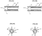
FIG. 3A is a partially enlarged schematic cross-sectional view illustrating a modification ofFIG. 1 . -
FIG. 3B is a partially enlarged schematic cross-sectional view illustrating a modification ofFIG. 1 . -
FIG. 4A is a schematic front view illustrating a modification ofFIG. 1 . -
FIG. 4B is a schematic front view illustrating a modification ofFIG. 1 . -
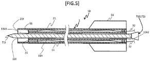
FIG. 5 is a schematic cross-sectional view illustrating a second embodiment of the present invention. -
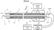
FIG. 6 is a schematic view illustrating a third embodiment of the present invention. -
FIG. 7A is an explanatory diagram of a fourth embodiment of the present invention. -
FIG. 7B is an explanatory diagram of the fourth embodiment of the present invention. -
FIG. 7C is an explanatory diagram of the fourth embodiment of the present invention. -
FIG. 7D is an explanatory diagram of the fourth embodiment of the present invention. -
FIG. 7E is an explanatory diagram of the fourth embodiment of the present invention. -
FIG. 7F is an explanatory diagram of the fourth embodiment of the present invention. -
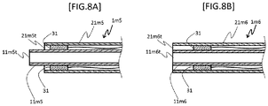
FIG. 8A is a partially enlarged schematic cross-sectional view illustrating a modification ofFIG. 1 . -
FIG. 8B is a partially enlarged schematic cross-sectional view illustrating a modification ofFIG. 1 . - Embodiments of a catheter, a catheter set, a medical instrument, and an ultrasonic measurement method according to the present disclosure will be described below with reference to the drawings, but the present invention is not limited only to the embodiments described in the drawings. Further, the dimensions of the catheter, the catheter set, and the medical instrument illustrated in the drawings are dimensions indicated to facilitate the understanding of the contents of implementation and do not correspond to the actual dimensions.
- The catheter is a catheter used with any one of a distal end of an inner shaft and a distal end of an outer shaft contacting an object and is characterized in including the inner shaft including a lumen along a longitudinal axis direction, the outer shaft provided to cover an outer periphery of the inner shaft, and an ultrasonic element that is located between the inner shaft and the outer shaft, is arranged on a proximal end side from at least any one of the distal end of the inner shaft and the distal end of the outer shaft, and is capable of transmitting and receiving ultrasonic waves.
-
FIG. 1 is a schematic cross-sectional view illustrating a first embodiment of the present invention.FIG. 2 is a schematic front view ofFIG. 1 . As illustrated inFIGS. 1 and 2 , acatheter 1 schematically includes aninner shaft 11, anouter shaft 21, anultrasonic element 31, and aconnector 51. It is noted that a method of using thecatheter 1 will be described in detail in <Ultrasonic Measurement Method> described later. - The
inner shaft 11 is a shaft including alumen 11h along the longitudinal axis direction. Specifically, theinner shaft 11 may be formed of a hollow-shaped shaft penetrating from the distal end to the proximal end, for example. For example, a therapeutic device 71 (described later), a medical solution (not illustrated), or the like is inserted through thelumen 11h of theinner shaft 11. - The
outer shaft 21 is a shaft provided to cover an outer periphery of theinner shaft 11. Specifically, theouter shaft 21 may be configured to hold theinner shaft 11 in alumen 21h and cover theinner shaft 11 over the entire length of theinner shaft 11 along a longitudinal axis direction. - The
outer shaft 21 is connected to theinner shaft 11. Examples of a method of connecting theouter shaft 21 and theinner shaft 11 may include a method in which aspacer member 41 is interposed between theouter shaft 21 and theinner shaft 11 and theouter shaft 21 and theinner shaft 11 are connected by thespacer member 41, a method in which a part of an inner peripheral surface of theouter shaft 21 and a part of an outer peripheral surface of theinner shaft 11 are joined by welding or the like, a method in which theouter shaft 21 and theinner shaft 11 are connected via theultrasonic element 31 described later, and a method obtained by combining these methods. In the present embodiment, theouter shaft 21 and theinner shaft 11 are adhered (fixed) by an adhesive via theultrasonic element 31 and thespacer member 41. - Materials forming the
inner shaft 11 and theouter shaft 21 are not particularly limited as long as an effect of the present invention is not impaired. If thecatheter 1 is used as a medical treatment device to be inserted into a body, materials forming each of theinner shaft 11 and theouter shaft 21 are preferably formed of materials having antithrombogenicity, flexibility, and biocompatibility, and an example of such materials include resin materials such as a polyamide resin, a polyolefin resin, a polyester resin, a polyurethane resin, a silicone resin, and a fluororesin. - Here, as for the dimensions of the
inner shaft 11 and theouter shaft 21, for example, an inner diameter of theinner shaft 11 may be set to 0.5 mm to 1.5 mm, a length of theinner shaft 11 may be set to 800 mm to 1500 mm, an inner diameter of theouter shaft 21 may be set to 0.8 mm to 4 mm, and a length of theouter shaft 21 may be set to 800 mm to 1500 mm. It is noted that a space into which a later-describedcord 32 for communication and power transmission extending from theultrasonic element 31 can be inserted is preferably provided between the outer peripheral surface of theinner shaft 11 and the inner peripheral surface of theouter shaft 21. - The
ultrasonic element 31 is an element that is located between theinner shaft 11 and theouter shaft 21, is arranged on a proximal end side from at least any one of adistal end 11t of theinner shaft 11 and adistal end 21t of theouter shaft 21, and is capable of transmitting and receiving ultrasonic waves. For example, as in thecatheter 1, theultrasonic element 31 may be fixed on an outer peripheral surface of a distal end portion of theinner shaft 11. An example of a method of connecting theultrasonic element 31 to theinner shaft 11 and theouter shaft 21 may include a method in which theultrasonic element 31 is adhesively fixed to each of the outer peripheral surface of theinner shaft 11 and the inner peripheral surface of theouter shaft 21 by an adhesive. - Examples of an ultrasonic element to be employed for the
ultrasonic element 31 include an ultrasonic element separately including a wave transmitter that transmits ultrasonic waves toward an object and a wave receiver that receives a reflected wave from an object, and an ultrasonic element including one ultrasonic transducer that alternately switches between a wave transmission mode and a wave reception mode to transmit and receive waves. An example of a frequency of ultrasonic waves transmitted from theultrasonic element 31 may include from 20 kHz to 1000 kHz. A pulse wave, a continuous wave, and the like may be employed for a waveform of the ultrasonic wave. The above pulse wave may be any one of a single pulse wave or a periodic or aperiodic pulse wave. - Here, as in the
catheter 1, thedistal end 21t of theouter shaft 21 is preferably located on a distal end side from thedistal end 11t of the inner shaft 11 (thedistal end 21t of theouter shaft 21 is formed to be separated toward the distal end side from thedistal end 11t of the inner shaft 11). In such a case, the shape of thedistal end 21t of theouter shaft 21 may include an annular flat surface orthogonal to the longitudinal axis direction as in thedistal end 21t of theouter shaft 21 in the catheter 1 (seeFIG. 1 ), an arc-shaped flat surface orthogonal to the longitudinal axis direction as in a distal end 21m1t of an outer shaft 21m1 in a catheter 1m1 (seeFIG. 3A ), and a convex curved surface curved toward the distal end side as in a distal end 21m2t of an outer shaft 21m2 in a catheter 1m2 (seeFIG. 3B ). It is noted that, in thecatheter 1, theultrasonic element 31 is fixed on the outer peripheral surface of the distal end portion of theinner shaft 11. Thedistal end 21t of theouter shaft 21 is located on the distal end side from thedistal end 11t of theinner shaft 11 as described above. Therefore, a reflected ultrasonic wave can be captured on the distal end side from thedistal end 11t of theinner shaft 11 without being blocked by theinner shaft 11 to sense a behavior in front of theinner shaft 11. - It is noted that the
ultrasonic element 31 may include a plurality of ultrasonic elements (each ultrasonic element is also referred to as the ultrasonic element 31), and it is preferable that the plurality ofultrasonic elements 31 are arranged along a circumferential direction of an outer periphery of theinner shaft 11. Examples of such a catheter include thecatheter 1 and a catheter 1m3 (seeFIGs. 2 and4A ), in which two or more of theultrasonic elements 31 are arranged at equal intervals in the circumferential direction along the outer periphery of theinner shaft 11, and a catheter 1m4 (seeFIG. 4B ) in which theultrasonic elements 31 are arranged at different intervals. If the plurality ofultrasonic elements 31 are arranged along the circumferential direction of the outer periphery of theinner shaft 11, one reflected wave can be received by the plurality ofultrasonic elements 31, and thus, it is possible to better understand a positional relationship between an object and a distal end portion of the catheter 1 (for example, a tilt of the longitudinal axis of theinner shaft 11 with respect to a surface of the object), based on a difference in reception times. - The
connector 51 is a member used by an operator to hold thecatheter 1. Theconnector 51 may be connected to cover a proximal end portion of theouter shaft 21, for example. It is noted that the shape of theconnector 51 is not particularly limited as long as an effect of the present invention is not impaired. - As described above, the
catheter 1 has the above-described configuration. Accordingly, because theultrasonic element 31 is arranged on the proximal end side from at least any one of thedistal end 11t of theinner shaft 11 and thedistal end 21t of theouter shaft 21, the object and theultrasonic element 31 can be located away from each other. Therefore, thecatheter 1 can surely determine a contact between thecatheter 1 and the object without excessively pressing the object to accurately measure a thickness and the like of the object. - The catheter set includes the above-described catheter according to the present disclosure and a therapeutic device being inserted into the lumen of the inner shaft and having a distal end portion that can advance further to a distal end side than a distal end of the inner shaft.
-
FIG. 5 is a schematic cross-sectional view illustrating a second embodiment of the present invention. As illustrated inFIG. 5 , a catheter set 10 schematically includes thecatheter 1 and thetherapeutic device 71. It is noted that a configuration of thecatheter 1 is similar to that in the first embodiment, and thus, the same parts as those of the first embodiment are designated by the same reference numerals, and detailed description thereof will be omitted here. Further, a method of using the catheter set 10 will be described in detail in <Ultrasonic Measurement Method> described later. - The
catheter 1 is a catheter used with any one of thedistal end 11t of theinner shaft 11 and thedistal end 21t of theouter shaft 21 contacting an object and includes theinner shaft 11 provided with thelumen 11h along the longitudinal axis direction, theouter shaft 21 provided to cover an outer periphery of theinner shaft 11, and theultrasonic element 31 that is located between theinner shaft 11 and theouter shaft 21, is arranged on a proximal end side from at least any one of thedistal end 11t of theinner shaft 11 and thedistal end 21t of theouter shaft 21, and is capable of transmitting and receiving ultrasonic waves. - The
therapeutic device 71 is a therapeutic device that is inserted into thelumen 11h of theinner shaft 11 and includes a distal end portion that can advance further to a distal end side than thedistal end 11t of theinner shaft 11. Specifically, for example, thetherapeutic device 71 can be configured so that thetherapeutic device 71 is inserted into thelumen 11h from thedistal end 11t to the proximal end of theinner shaft 11, and adistal end 71t of thetherapeutic device 71 advancing from an opening 11k1 of thedistal end 11t of theinner shaft 11 protrudes toward the distal end side beyond thedistal end 21t of theouter shaft 21. On the other hand, a proximal end of thetherapeutic device 71 may be arranged to pass through theinner shaft 11 and be exposed from an opening 11k2 of the proximal end of theinner shaft 11. - Examples of the
therapeutic device 71 include a puncture needle, a dilator, and a ablation device. In the present embodiment, apuncture needle 711 is described as an example of thetherapeutic device 71. - Here, the
ultrasonic element 31 described above can be used to recognize, for example, a positional relationship between the distal end portion of thetherapeutic device 71 advancing from the opening 11k1 of thedistal end 11t of theinner shaft 11 and/or thedistal end 21t of theouter shaft 21, or a positional relationship between the distal end portion of thetherapeutic device 71 and a surface of an object and/or a tissue inside the object and the like. Specifically, because an ultrasonic wave reflected by the therapeutic device 71 (for example, thedistal end 71t of the therapeutic device 71) is detected, it is possible to recognize a position of the therapeutic device 71 (for example, a position of thedistal end 71t with respect to theultrasonic element 31 in the longitudinal axis direction), based on the time required for the ultrasonic wave to be reflected. - As described above, the catheter set 10 has the above-described configuration. Accordingly, it is possible to recognize positions of the
distal end 11t of theinner shaft 11, thedistal end 21t of theouter shaft 21, and the distal end portion (thedistal end 71t or the like) of thetherapeutic device 71 by ultrasonic measurement, and thus, a positional relationship between the distal end portion of thetherapeutic device 71 and an object or the like can be accurately recognized. As a result, thetherapeutic device 71 can be used to surely treat the object. - A medical instrument includes the above-described catheter according to the present disclosure, a therapeutic device being inserted into a lumen of an inner shaft and having a distal end portion that can advance further to a distal end side than a distal end of the inner shaft, a first drive device that advances and retreats the catheter into and from a body cavity, a second drive device that advances and retreats the therapeutic device, and a control device that controls the first drive device and the second drive device.
-
FIG. 6 is a schematic view illustrating a third embodiment of the present invention. As illustrated inFIG. 6 , amedical instrument 100 schematically includes thecatheter 1, thetherapeutic device 71, afirst drive device 611, asecond drive device 612, acontrol device 613, a measurement andcalculation device 614, and adetermination device 615. It is noted that configurations of thecatheter 1 and thetherapeutic device 71 are similar to those in the first and second embodiments, and thus, the same parts as those of the first and second embodiments are designated by the same reference numerals, and detailed description thereof will be omitted here. Further, a method of using themedical instrument 100 will be described in detail later in the section <Ultrasonic Measurement Method>. - The
catheter 1 is a catheter used with any one of thedistal end 11t of theinner shaft 11 and thedistal end 21t of theouter shaft 21 contacting an object and includes theinner shaft 11 provided with thelumen 11h along the longitudinal axis direction, theouter shaft 21 provided to cover an outer periphery of theinner shaft 11, and theultrasonic element 31 that is located between theinner shaft 11 and theouter shaft 21, is arranged on a proximal end side from at least any one of thedistal end 11t of theinner shaft 11 and thedistal end 21t of theouter shaft 21, and is capable of transmitting and receiving ultrasonic waves. - The
therapeutic device 71 is a therapeutic device that is inserted into thelumen 11h of theinner shaft 11 and includes a distal end portion that can advance further to the distal end side than thedistal end 11h of theinner shaft 11. In the present embodiment, thepuncture needle 711 is described as an example of thetherapeutic device 71. - Here, the
ultrasonic element 31 described above can be used to recognize, for example, a positional relationship between the distal end portion of thetherapeutic device 71 advancing from the opening 11k1 of thedistal end 11t of theinner shaft 11 and/or thedistal end 21t of theouter shaft 21, or a positional relationship between the distal end portion of thetherapeutic device 71 and a surface of an object and/or a tissue inside the object and the like. Specifically, because an ultrasonic wave reflected by the therapeutic device 71 (for example, thedistal end 71t of the therapeutic device 71) is detected, it is possible to recognize a position of the therapeutic device 71 (for example, a position of thedistal end 71t with respect to theultrasonic element 31 in the longitudinal axis direction), based on the time required for the ultrasonic wave to be reflected. - The
first drive device 611 is a device that advances and retreats thecatheter 1 into and from a body cavity. Thefirst drive device 611 is provided in theconnector 51, for example, and may be configured to advance and retreat thecatheter 1 along the longitudinal axis direction of theinner shaft 11 while engaging with the outer periphery of theouter shaft 21. A range in which thecatheter 1 is advanced and retreated depends on a distance in which thecatheter 1 is moved inside a body, but can be set to a range between a position where theconnector 51 and the distal end portion of thecatheter 1 coincide and a position where theconnector 51 and the proximal end portion of thecatheter 1 coincide, for example. - The
second drive device 612 is a device that advances and retreats the therapeutic device. Thesecond drive device 612 is provided in theconnector 51, for example, and may be configured to advance and retreat thetherapeutic device 71 in thelumen 11h of theinner shaft 11 along the longitudinal axis direction of theinner shaft 11 while engaging with the outer periphery of thetherapeutic device 71. A range in which thetherapeutic device 71 is advanced and retreated depends on a treatment content, but can be set to a range between a position where thedistal end 71t of thetherapeutic device 71 is within theinner shaft 11 and a position where thedistal end 71t of thetherapeutic device 71 exceeds thedistal end 21t of theouter shaft 21 to enter the object (for example, a position of a treatment site). - For example, a linear actuator, a linear motor, and an ultrasonic motor can be employed for the
first drive device 611 and thesecond drive device 612 described above. - The
control device 613 is a device that controls thefirst drive device 611 and thesecond drive device 612. Specifically, thecontrol device 613 controls thefirst drive device 611, for example, based on a distance from theultrasonic element 31 to a furthermost end among the distal ends of theinner shaft 11 and the outer shaft 21 (distance-to-furthermost end) and a time until theultrasonic element 31 receives a reflected wave reflected off a surface of an object, so that thedistal end 11t of theinner shaft 11 and/or thedistal end 21t of theouter shaft 21 contacts the surface of the object. Further, thecontrol device 613 controls thesecond drive device 612, for example, based on a reflected wave reflected by a distal end of thetherapeutic device 71 advancing from the opening 11k1 via thelumen 11h of theinner shaft 11, so that thedistal end 71t of thetherapeutic device 71 is located at a desired site. - The measurement and
calculation device 614 measures, for example, a timing for transmitting and receiving ultrasonic waves by theultrasonic element 31, measures first to third times described later using the measurement/calculation value 614, and to calculate a distance to each site, a thickness of the object, and the like using these measured times. - The
determination device 615 uses a result calculated by the measurement andcalculation device 614 to determine, for example, whether thedistal end 11t of theinner shaft 11 and/or thedistal end 21t of theouter shaft 21 contacts the surface of the object and whether an insertion depth of an insertion body into the object is appropriate. - As described above, if the
medical instrument 100 has the above-described configuration. Accordingly, it is possible to recognize positions of thedistal end 11t of theinner shaft 11, thedistal end 21t of theouter shaft 21, and the distal end portion (thedistal end 71t or the like) of thetherapeutic device 71 by ultrasonic measurement, and thus, a positional relationship between the distal end portion of thetherapeutic device 71 and an object or the like can be accurately recognized. As a result, thetherapeutic device 71 can be used to surely treat the object. - The ultrasonic measurement method is an ultrasonic measurement method used with any one of a distal end of an inner shaft and a distal end of an outer shaft contacting an object. The ultrasonic measurement method includes, using the catheter according to the present disclosure,
- (S1) a first step of transmitting an ultrasonic wave from an ultrasonic element,
- (S2) after the first step, a second step of receiving, by the ultrasonic element, a reflected wave (a first reflected wave) reflected off a surface of the object and measuring a time (first time) from the transmission of the ultrasonic wave to the reception of the first reflected wave, and
- (S3) after the second step, a third step of determining whether the distal end of the inner shaft and/or the distal end of the outer shaft contacts the surface of the object, based on the first time and a longer distance between a distance from an arrangement position of the ultrasonic element to the distal end of the inner shaft and a distance from the arrangement position of the ultrasonic element to the distal end of the outer shaft.
- Further, the ultrasonic measurement method preferably includes (S4) after confirming that the distal end of the inner shaft and/or the distal end of the outer shaft contacts the surface of the object in the third step, a fourth step of receiving, by the ultrasonic element, a reflected wave (a second reflected wave) reflected by a deep portion deeper than the surface of the object, and measuring a time (second time) from the transmission of the ultrasonic wave to the reception of the second reflected wave, and
(S5) after the fourth step, a fifth step of calculating a thickness of the object, based on the first time and the second time. - Further, the ultrasonic measurement method preferably includes (S6) after confirming that the distal end of the inner shaft and/or the distal end of the outer shaft contacts the surface of the object in the third step, a sixth step of inserting an insertion body into the object via a lumen of the inner shaft, and
(S7) after the sixth step, a seventh step of receiving, by the ultrasonic element, a reflected wave (a third reflected wave) reflected by the insertion body and measuring a time (third time) from the transmission of the ultrasonic wave to the reception of the third reflected wave. - Further, the ultrasonic measurement method preferably includes (S8) after the seventh step, an eighth step of determining whether an insertion depth of the insertion body into the object is appropriate, based on the first time, the second time, and the third time.
- The ultrasonic measurement method can be suitably applied to uses of the
catheter 1, the catheter set 10, and themedical instrument 100 described above. Therefore, thecatheter 1, the catheter set 10, and themedical instrument 100 are described as examples, but the application of the ultrasonic measurement method is not limited only to the use of thecatheter 1, the catheter set 10, and themedical instrument 100. - An embodiment of the ultrasonic measurement method will be described below with reference to
FIGs. 7A to 7F . It is noted that the therapeutic device 71 (the puncture needle 711) is described herein as an example of the insertion body. - In step S1, a catheter is used to transmit ultrasonic waves from an ultrasonic element. In the first step S1, specifically, for example, after inserting the
catheter 1 into a blood vessel from a distal end of thecatheter 1, an operator operates thecontrol device 613 while grasping theconnector 51, to operate thefirst drive device 611 and push ahead the distal end of thecatheter 1 to the vicinity of an object b. Subsequently, for example, a periodic pulse wave (an ultrasonic wave W0) having a predetermined frequency is transmitted from theultrasonic element 31 substantially toward the distal end side (seeFIG. 7A ). - In step S2, after the first step S1, a first reflected wave reflected by a surface of an object is received by the ultrasonic element and a first time from the transmission of the ultrasonic wave to the reception of the first reflected wave is measured. Specifically, in the second step S2, for example, the
ultrasonic element 31 is used to receive a first reflected wave W1 of the ultrasonic wave W0 transmitted in the first step S1 (seeFIG. 7B ) and the measurement andcalculation device 614 is used to measure a first time T1 from the transmission of the ultrasonic wave to the reception of the first reflected wave W1 by theultrasonic element 31. - In step S3, after the second step S2, it is determined whether the distal end of the inner shaft and/or the distal end of the outer shaft contacts the surface of the object, based on the first time and a longer distance between a distance from an arrangement position of the ultrasonic element to the distal end of the inner shaft and a distance from the arrangement position of the ultrasonic element to the distal end of the outer shaft. In the third step S3, specifically, for example, the
determination device 615 is used to compare a distance from theultrasonic element 31 to a furthermost end among the distal ends of theinner shaft 11 and the outer shaft 21 (a distance-to-furthermost end L0), with a distance between theultrasonic element 31 and a surface s1 of the object b (a first distance L1) obtained from the first time T1. At this time, if the first distance L1 is larger than the distance-to-furthermost end L0 (L1 > L0), thedetermination device 615 determines that thedistal end 11t of theinner shaft 11 and thedistal end 21t of theouter shaft 21 are separated from the object b (seeFIG. 7B ). On the other hand, if the first distance L1 and the distance-to-furthermost end L0 are the same (L1 = L0), thedetermination device 615 determines that thedistal end 11t of theinner shaft 11 and/or thedistal end 21t of theouter shaft 21 contacts the object (seeFIG. 7C ). - As described above, the ultrasonic measurement method includes the first step S1, the second step S2, and the third step S3, and thus, it is possible to surely determine whether the object b contacts the
distal end 11t of theinner shaft 11 and/or thedistal end 21t of theouter shaft 21 without excessively pressing the object b. - In step S4, after confirming that the distal end of the inner shaft and/or the distal end of the outer shaft contacts the surface of the object in the third step S3, a second reflected wave reflected by a deep portion deeper than the surface of the object, is received by the ultrasonic element and a second time from the transmission of the ultrasonic wave to the reception of the second reflected wave is measured. Specifically, in the fourth step S4, for example, the
ultrasonic element 31 is used to receive a second reflected wave W2 formed when the ultrasonic wave W0 transmitted in the first step S1 is reflected off an interface s2 of a deep portion (an interface on a distal end side from the surface s1 of the object b) (seeFIG. 7D ), and the measurement andcalculation device 614 is used to measure a second time T2 from the transmission of the ultrasonic wave W0 to the reception of the second reflected wave W2 by theultrasonic element 31. - In step S5, after the fourth step S4, a thickness of the object is calculated based on the first time and the second time. In the fifth step S5, specifically, for example, the measurement and
calculation device 614 uses the first time T1 measured in the second step S2 and the second time T2 measured in the fourth step S4 to calculate a difference (L2 - L1) between the first distance L1 converted from the first time T1 and a distance (a second distance L2) converted from the second time T2, and then, calculates a thickness L of the object (seeFIG. 7D ). It is noted that the second reflected wave received in the fourth step is a reflected wave reflected from an opposite surface in a depth direction facing the surface of the object against which the distal end of the inner shaft and/or the distal end of the outer shaft abuts, or from a lesion existing inside a wall surface of the object. Therefore, a depth of the lesion can be calculated using the second reflected wave, for example. - As described above, the ultrasonic measurement method further includes the fourth step S4 and the fifth step S5 described above, and thus, the thickness L of the object b can be accurately measured without excessively pressing the object b, and for example, a shape of the lesion and/or a depth of the lesion can be detected more accurately.
- In step S6, after confirming that the distal end of the inner shaft and/or the distal end of the outer shaft contacts the surface of the object in the third step S3, the insertion body is inserted into the object via the lumen of the inner shaft. In the sixth step S6, specifically, for example, after inserting the therapeutic device 71 (the puncture needle 711) from the opening 11k2 at the proximal end of the inner shaft 11 (see
FIG. 6 ), the operator operates thecontrol device 613 while grasping theconnector 51, to operate thesecond drive device 612 and advance the distal end portion of thetherapeutic device 71 from the opening 11k1 at thedistal end 11t of theinner shaft 11. Next, thesecond drive device 612 advances thedistal end 11t of theinner shaft 11 to puncture the object b (seeFIG. 7E ). - In step S7, after the sixth step S6, a third reflected wave reflected by the insertion body is received by the ultrasonic element and a third time from the transmission of the ultrasonic wave to the reception of the third reflected wave is measured. Specifically, in the seventh step S7, for example, a third reflected wave W3 of an ultrasonic wave transmitted from the
ultrasonic element 31 and reflected by thedistal end 71t of thetherapeutic device 71 is received (seeFIG. 7F ) and the measurement andcalculation device 614 is used to measure a third time T3 from the transmission of the ultrasonic wave W0 to the reception of the third reflected wave W3 by theultrasonic element 31. Further, in the seventh step S7, a difference (L3 - L1) between the first distance L1 converted from the first time T1 measured in the second step S2 and a distance (a third distance L3) converted from the above-mentioned third time T3 is calculated to confirm that thedistal end 71t punctures the surface s1 of the object b. - As described above, the ultrasonic measurement method further includes the sixth step S6 and the seventh step S7 described above, and thus, it is possible to surely recognize whether the
distal end 71t of thetherapeutic device 71 enters the surface s1 of the object b, based on the first and third times T1 and T3. - In step S8, after the seventh step S7, it is determined whether an insertion depth of the insertion body into the object is appropriate, based on the first time, the second time, and the third time. In the eighth step S8, specifically, for example, a difference (L2 - L1) between the first distance L1 converted from the first time T1 measured in the second step S2 and the second distance L2 converted from the second time T2 measured in the fourth step S4, and the difference (L3 - L1) between the first distance L1 converted from the first time T1 measured in the second step S2 and the third distance L3 converted from the third time T3 measured in the seventh step S7, are used to evaluate a position (a depth M) of the
distal end 71t of the therapeutic device in the object b. Next, thedetermination device 615 is used to determine whether the evaluated position of thedistal end 71t is within a predetermined range (seeFIG. 7F ). - As described above, the ultrasonic measurement method further includes the eighth step S8, and thus, the position of the therapeutic device 71 (the puncture needle 711) (in particular, the position of the
distal end 71t of the therapeutic device ) in the object b can be surely recognized, based on the first to third times T1 to T3. As a result, thetherapeutic device 71 can be used to more accurately treat the lesion or the like (the object b). - It is noted that after treatment using the
therapeutic device 71 at a desired position in the object b based on the determination in the eighth step S8, thesecond drive device 612 is used to remove thetherapeutic device 71 from the object b, and further, thefirst drive device 611 is used to remove thecatheter 1 from the body, and thereby, a procedure using thecatheter 1, the catheter set 10, and themedical instrument 100 is completed. - The present invention is not limited to the configuration of the above-described embodiments, but is indicated by the claims, and is intended to include all modifications within meanings and the scope equivalent to the claims.
- For example, in the first embodiment described above, the
catheter 1 in which thedistal end 21t of theouter shaft 21 is located on the distal end side from thedistal end 11t of theinner shaft 11 is described. However, a catheter 1m5 in which a distal end 11m5t of an inner shaft 11m5 is located on the distal end side from a distal end 21m5t of an outer shaft 21m5 (seeFIG. 8A ) and a catheter 1m6 in which a position of a distal end 21m6t of an outer shaft 21m6 and a position of a distal end 11m6t of an inner shaft 11m6 are the same in the longitudinal axis direction (seeFIG. 8B ) can be employed. - Further, in the first embodiment described above, the
catheter 1 including the plurality ofultrasonic elements 31 arranged along the circumferential direction of the outer periphery of theinner shaft 11 is described. However, a catheter including only one ultrasonic element (not illustrated) may also be employed. -
- b
- Object
- 1
- Catheter
- 11
- Inner shaft
- 11h
- Lumen
- 21
- Outer shaft
- 31
- Ultrasonic element
- 611
- First drive device
- 612
- Second drive device
- 613
- Control device
- 71
- Therapeutic device (insertion body)
- 10
- Catheter set
- 100
- Medical instrument
Claims (9)
- A catheter used with any one of a distal end of an inner shaft and a distal end of an outer shaft contacting an object, the catheter comprising:an inner shaft including a lumen along a longitudinal axis direction;an outer shaft provided to cover an outer periphery of the inner shaft; andan ultrasonic element that is located between the inner shaft and the outer shaft, is arranged on a proximal end side from at least any one of the distal end of the inner shaft and the distal end of the outer shaft, and is capable of transmitting and receiving ultrasonic waves.
- The catheter according to claim 1, wherein the distal end of the outer shaft is located on a distal end side from the distal end of the inner shaft.
- The catheter according to claim 1 or 2, wherein the ultrasonic element includes a plurality of ultrasonic elements, and
the plurality of ultrasonic elements are arranged along a circumferential direction of the outer periphery of the inner shaft. - A catheter set, comprising:the catheter according to any one of claims 1 to 3; anda therapeutic device being inserted into the lumen of the inner shaft and including a distal end portion capable of advancing further to a distal end side than the distal end of the inner shaft.
- An ultrasonic measurement method used with any one of a distal end of an inner shaft and a distal end of an outer shaft contacting an object, the ultrasonic measurement method using a catheter, the catheter including:an inner shaft including a lumen along a longitudinal axis direction;an outer shaft provided to cover an outer periphery of the inner shaft; andan ultrasonic element that is located between the inner shaft and the outer shaft, is arranged on a proximal end side from at least any one of the distal end of the inner shaft and the distal end of the outer shaft, and is capable of transmitting and receiving ultrasonic waves, the ultrasonic measurement method comprising:a first step of transmitting an ultrasonic wave from the ultrasonic element;after the first step, a second step of receiving, by the ultrasonic element, a first reflected wave reflected off a surface of the object and measuring a first time from a transmission of the ultrasonic wave to a reception of the first reflected wave;after the second step, a third step of determining whether the distal end of the inner shaft and/or the distal end of the outer shaft contacts the surface of the object, based on the first time and a longer distance between a distance from an arrangement position of the ultrasonic element to the distal end of the inner shaft and a distance from the arrangement position of the ultrasonic element to the distal end of the outer shaft.
- The ultrasonic measurement method according to claim 5, comprising:after confirming that the distal end of the inner shaft and/or the distal end of the outer shaft contacts the surface of the object in the third step, a fourth step of receiving, by the ultrasonic element, a second reflected wave reflected by a deep portion deeper than the surface of the object, and measuring a second time from the transmission of the ultrasonic wave to a reception of the second reflected wave; andafter the fourth step, a fifth step of calculating a thickness of the object, based on the first time and the second time.
- The ultrasonic measurement method according to claim 5 or 6, comprising:after confirming that the distal end of the inner shaft and/or the distal end of the outer shaft contacts the surface of the object in the third step, a sixth step of inserting an insertion body into the object via the lumen of the inner shaft; andafter the sixth step, a seventh step of receiving, by the ultrasonic element, a third reflected wave reflected by the insertion body and measuring a third time from the transmission of the ultrasonic wave to a reception of the third reflected wave.
- The ultrasonic measurement method according to claim 7, comprising:
after the seventh step, an eighth step of determining whether an insertion depth of the insertion body into the object is appropriate, based on the first time, the second time, and the third time. - A medical instrument, comprising:the catheter according to any one of claims 1 to 3;a therapeutic device being inserted into the lumen of the inner shaft and including a distal end portion capable of advancing further to a distal end side than the distal end of the inner shaft;a first drive device that advances and retreats the catheter into and from a body cavity;a second drive device that advances and retreats the therapeutic device; anda control device that controls the first drive device and the second drive device.
Applications Claiming Priority (2)
| Application Number | Priority Date | Filing Date | Title |
|---|---|---|---|
| JP2019116508A JP7202263B2 (en) | 2019-06-24 | 2019-06-24 | Catheters, catheter sets, and medical devices |
| PCT/JP2020/022935 WO2020262001A1 (en) | 2019-06-24 | 2020-06-10 | Catheter, catheter set, medical device, and ultrasonic measurement method |
Publications (2)
| Publication Number | Publication Date |
|---|---|
| EP3988030A1 true EP3988030A1 (en) | 2022-04-27 |
| EP3988030A4 EP3988030A4 (en) | 2023-08-02 |
Family
ID=73994447
Family Applications (1)
| Application Number | Title | Priority Date | Filing Date |
|---|---|---|---|
| EP20831879.0A Withdrawn EP3988030A4 (en) | 2019-06-24 | 2020-06-10 | Catheter, catheter set, medical device, and ultrasonic measurement method |
Country Status (5)
| Country | Link |
|---|---|
| US (1) | US20220104792A1 (en) |
| EP (1) | EP3988030A4 (en) |
| JP (1) | JP7202263B2 (en) |
| CN (1) | CN114080187A (en) |
| WO (1) | WO2020262001A1 (en) |
Families Citing this family (1)
| Publication number | Priority date | Publication date | Assignee | Title |
|---|---|---|---|---|
| JP2025510283A (en) * | 2022-03-28 | 2025-04-14 | デューク ユニバーシティ | Systems and methods for treating cancer using ultrasound |
Family Cites Families (18)
| Publication number | Priority date | Publication date | Assignee | Title |
|---|---|---|---|---|
| JPH03280939A (en) * | 1990-03-29 | 1991-12-11 | Fujitsu Ltd | Ultrasonic probe |
| JPH05285140A (en) * | 1992-04-09 | 1993-11-02 | Hitachi Ltd | Ultrasonic device |
| US5368037A (en) * | 1993-02-01 | 1994-11-29 | Endosonics Corporation | Ultrasound catheter |
| US7226417B1 (en) * | 1995-12-26 | 2007-06-05 | Volcano Corporation | High resolution intravascular ultrasound transducer assembly having a flexible substrate |
| US6672312B2 (en) * | 2001-01-31 | 2004-01-06 | Transurgical, Inc. | Pulmonary vein ablation with myocardial tissue locating |
| JP3553923B2 (en) | 2002-05-28 | 2004-08-11 | 独立行政法人 科学技術振興機構 | Forward looking ultrasonic probe and method of manufacturing the same |
| EP1858417A1 (en) | 2005-02-28 | 2007-11-28 | Wilson-Cook Medical Inc. | Echogenic markers on gi medical devices |
| CA2652126C (en) * | 2006-05-12 | 2015-12-01 | Hira V. Thapliyal | Device for ablating body tissue |
| JP5403785B2 (en) * | 2008-10-15 | 2014-01-29 | 国立大学法人 名古屋工業大学 | Insertion device |
| AU2009313687B2 (en) * | 2008-11-17 | 2015-11-26 | Vytronus, Inc. | Systems and methods for ablating body tissue |
| DE112010002450B4 (en) * | 2009-06-12 | 2017-12-07 | Technische Universität Dresden | Arrangement and method for the combined determination of sound velocities and distances in media by means of ultrasound |
| US9694213B2 (en) | 2009-12-31 | 2017-07-04 | St. Jude Medical, Atrial Fibrillation Division, Inc. | Acoustic coupling for assessment and ablation procedures |
| JP2012000194A (en) * | 2010-06-15 | 2012-01-05 | Hitachi Aloka Medical Ltd | Medical system |
| JP5678669B2 (en) * | 2011-01-06 | 2015-03-04 | セイコーエプソン株式会社 | Ultrasonic sensor, tactile sensor, and gripping device |
| JP5840910B2 (en) * | 2011-10-17 | 2016-01-06 | 日立Geニュークリア・エナジー株式会社 | Ultrasonic flaw detection method |
| US10327734B2 (en) | 2014-12-30 | 2019-06-25 | Biosense Webster (Israel) Ltd. | Measurement of tissue thickness using ultrasound and force measurements |
| JP2018521802A (en) * | 2015-08-05 | 2018-08-09 | コーニンクレッカ フィリップス エヌ ヴェKoninklijke Philips N.V. | Catheter assembly with low axial sliding friction |
| JP6794226B2 (en) | 2016-11-07 | 2020-12-02 | テルモ株式会社 | Diagnostic imaging device, operating method and program of diagnostic imaging device |
-
2019
- 2019-06-24 JP JP2019116508A patent/JP7202263B2/en active Active
-
2020
- 2020-06-10 WO PCT/JP2020/022935 patent/WO2020262001A1/en not_active Ceased
- 2020-06-10 CN CN202080045665.8A patent/CN114080187A/en not_active Withdrawn
- 2020-06-10 EP EP20831879.0A patent/EP3988030A4/en not_active Withdrawn
-
2021
- 2021-12-15 US US17/551,939 patent/US20220104792A1/en not_active Abandoned
Also Published As
| Publication number | Publication date |
|---|---|
| JP7202263B2 (en) | 2023-01-11 |
| EP3988030A4 (en) | 2023-08-02 |
| WO2020262001A1 (en) | 2020-12-30 |
| US20220104792A1 (en) | 2022-04-07 |
| CN114080187A (en) | 2022-02-22 |
| JP2021000359A (en) | 2021-01-07 |
Similar Documents
| Publication | Publication Date | Title |
|---|---|---|
| US6656136B1 (en) | Use of focused ultrasound for vascular sealing | |
| JP6322210B2 (en) | Devices, systems, and methods for targeted intubation | |
| JP4972639B2 (en) | Method and apparatus for guiding and positioning an intravascular device | |
| CN103732273B (en) | Ultrasound-guided puncture needle and indwelling needle | |
| US20100305428A1 (en) | Ultrasonic guidance of subcutaneous tunneling | |
| WO2007047993A2 (en) | System and methods for sealing a vascular opening | |
| JP2006288755A (en) | Medical treatment equipment | |
| EP1962694A1 (en) | Device and method for determining the location of a vascular opening prior to application of hifu energy to seal the opening | |
| WO2013176098A1 (en) | Puncture device | |
| TW201434443A (en) | Ultrasonic probe and method for guiding puncture | |
| JP2014124452A (en) | Medicine injection system | |
| US20220104792A1 (en) | Catheter, catheter set, medical instrument, and ultrasonic measurement method | |
| EP3603530B1 (en) | Ultrasonic diagnosis device | |
| KR101586977B1 (en) | Spine pedicle view guide device for safe pedicle screw fixation or vertebroplasty using ultrasonic imaging | |
| JP3641427B2 (en) | Endoscopic ultrasound probe | |
| JP3504428B2 (en) | Ultrasonic diagnostic device in body cavity | |
| JPH07222748A (en) | Ultrasonic wave probe for blood vessel | |
| WO2020179410A1 (en) | Medical device | |
| JPH02215447A (en) | Applicator for embedded sensor | |
| KR20170022572A (en) | Ultrasonic image apparatus having function of pneumatic injection |
Legal Events
| Date | Code | Title | Description |
|---|---|---|---|
| STAA | Information on the status of an ep patent application or granted ep patent |
Free format text: STATUS: THE INTERNATIONAL PUBLICATION HAS BEEN MADE |
|
| PUAI | Public reference made under article 153(3) epc to a published international application that has entered the european phase |
Free format text: ORIGINAL CODE: 0009012 |
|
| STAA | Information on the status of an ep patent application or granted ep patent |
Free format text: STATUS: REQUEST FOR EXAMINATION WAS MADE |
|
| 17P | Request for examination filed |
Effective date: 20220103 |
|
| AK | Designated contracting states |
Kind code of ref document: A1 Designated state(s): AL AT BE BG CH CY CZ DE DK EE ES FI FR GB GR HR HU IE IS IT LI LT LU LV MC MK MT NL NO PL PT RO RS SE SI SK SM TR |
|
| DAV | Request for validation of the european patent (deleted) | ||
| DAX | Request for extension of the european patent (deleted) | ||
| A4 | Supplementary search report drawn up and despatched |
Effective date: 20230705 |
|
| RIC1 | Information provided on ipc code assigned before grant |
Ipc: A61B 8/08 20060101ALI20230629BHEP Ipc: A61M 25/00 20060101ALI20230629BHEP Ipc: A61B 17/00 20060101ALI20230629BHEP Ipc: A61B 8/12 20060101AFI20230629BHEP |
|
| STAA | Information on the status of an ep patent application or granted ep patent |
Free format text: STATUS: EXAMINATION IS IN PROGRESS |
|
| 17Q | First examination report despatched |
Effective date: 20250207 |
|
| STAA | Information on the status of an ep patent application or granted ep patent |
Free format text: STATUS: THE APPLICATION HAS BEEN WITHDRAWN |
|
| 18W | Application withdrawn |
Effective date: 20250307 |