EP3987167B1 - Wirbelantrieb mit reaktionskontrolle - Google Patents
Wirbelantrieb mit reaktionskontrolle Download PDFInfo
- Publication number
- EP3987167B1 EP3987167B1 EP20827630.3A EP20827630A EP3987167B1 EP 3987167 B1 EP3987167 B1 EP 3987167B1 EP 20827630 A EP20827630 A EP 20827630A EP 3987167 B1 EP3987167 B1 EP 3987167B1
- Authority
- EP
- European Patent Office
- Prior art keywords
- monopropellant
- vortex
- combustion chamber
- decomposed
- flow rate
- Prior art date
- Legal status (The legal status is an assumption and is not a legal conclusion. Google has not performed a legal analysis and makes no representation as to the accuracy of the status listed.)
- Active
Links
Images


Classifications
-
- F—MECHANICAL ENGINEERING; LIGHTING; HEATING; WEAPONS; BLASTING
- F02—COMBUSTION ENGINES; HOT-GAS OR COMBUSTION-PRODUCT ENGINE PLANTS
- F02K—JET-PROPULSION PLANTS
- F02K9/00—Rocket-engine plants, i.e. plants carrying both fuel and oxidant therefor; Control thereof
- F02K9/08—Rocket-engine plants, i.e. plants carrying both fuel and oxidant therefor; Control thereof using solid propellants
- F02K9/28—Rocket-engine plants, i.e. plants carrying both fuel and oxidant therefor; Control thereof using solid propellants having two or more propellant charges with the propulsion gases exhausting through a common nozzle
-
- F—MECHANICAL ENGINEERING; LIGHTING; HEATING; WEAPONS; BLASTING
- F02—COMBUSTION ENGINES; HOT-GAS OR COMBUSTION-PRODUCT ENGINE PLANTS
- F02K—JET-PROPULSION PLANTS
- F02K9/00—Rocket-engine plants, i.e. plants carrying both fuel and oxidant therefor; Control thereof
- F02K9/42—Rocket-engine plants, i.e. plants carrying both fuel and oxidant therefor; Control thereof using liquid or gaseous propellants
-
- F—MECHANICAL ENGINEERING; LIGHTING; HEATING; WEAPONS; BLASTING
- F02—COMBUSTION ENGINES; HOT-GAS OR COMBUSTION-PRODUCT ENGINE PLANTS
- F02K—JET-PROPULSION PLANTS
- F02K9/00—Rocket-engine plants, i.e. plants carrying both fuel and oxidant therefor; Control thereof
- F02K9/42—Rocket-engine plants, i.e. plants carrying both fuel and oxidant therefor; Control thereof using liquid or gaseous propellants
- F02K9/425—Propellants
-
- F—MECHANICAL ENGINEERING; LIGHTING; HEATING; WEAPONS; BLASTING
- F02—COMBUSTION ENGINES; HOT-GAS OR COMBUSTION-PRODUCT ENGINE PLANTS
- F02K—JET-PROPULSION PLANTS
- F02K9/00—Rocket-engine plants, i.e. plants carrying both fuel and oxidant therefor; Control thereof
- F02K9/42—Rocket-engine plants, i.e. plants carrying both fuel and oxidant therefor; Control thereof using liquid or gaseous propellants
- F02K9/44—Feeding propellants
-
- F—MECHANICAL ENGINEERING; LIGHTING; HEATING; WEAPONS; BLASTING
- F02—COMBUSTION ENGINES; HOT-GAS OR COMBUSTION-PRODUCT ENGINE PLANTS
- F02K—JET-PROPULSION PLANTS
- F02K9/00—Rocket-engine plants, i.e. plants carrying both fuel and oxidant therefor; Control thereof
- F02K9/42—Rocket-engine plants, i.e. plants carrying both fuel and oxidant therefor; Control thereof using liquid or gaseous propellants
- F02K9/44—Feeding propellants
- F02K9/56—Control
- F02K9/58—Propellant feed valves
-
- F—MECHANICAL ENGINEERING; LIGHTING; HEATING; WEAPONS; BLASTING
- F02—COMBUSTION ENGINES; HOT-GAS OR COMBUSTION-PRODUCT ENGINE PLANTS
- F02K—JET-PROPULSION PLANTS
- F02K9/00—Rocket-engine plants, i.e. plants carrying both fuel and oxidant therefor; Control thereof
- F02K9/42—Rocket-engine plants, i.e. plants carrying both fuel and oxidant therefor; Control thereof using liquid or gaseous propellants
- F02K9/60—Constructional parts; Details not otherwise provided for
- F02K9/68—Decomposition chambers
-
- F—MECHANICAL ENGINEERING; LIGHTING; HEATING; WEAPONS; BLASTING
- F02—COMBUSTION ENGINES; HOT-GAS OR COMBUSTION-PRODUCT ENGINE PLANTS
- F02K—JET-PROPULSION PLANTS
- F02K9/00—Rocket-engine plants, i.e. plants carrying both fuel and oxidant therefor; Control thereof
- F02K9/72—Rocket-engine plants, i.e. plants carrying both fuel and oxidant therefor; Control thereof using liquid and solid propellants, i.e. hybrid rocket-engine plants
-
- F—MECHANICAL ENGINEERING; LIGHTING; HEATING; WEAPONS; BLASTING
- F05—INDEXING SCHEMES RELATING TO ENGINES OR PUMPS IN VARIOUS SUBCLASSES OF CLASSES F01-F04
- F05D—INDEXING SCHEME FOR ASPECTS RELATING TO NON-POSITIVE-DISPLACEMENT MACHINES OR ENGINES, GAS-TURBINES OR JET-PROPULSION PLANTS
- F05D2240/00—Components
- F05D2240/10—Stators
- F05D2240/12—Fluid guiding means, e.g. vanes
- F05D2240/127—Vortex generators, turbulators, or the like, for mixing
Definitions
- the subject matter described herein relates to a vortex thruster system that can generate various thrust levels.
- Design requirements for a rocket combustion engine can include competing or conflicting requirements.
- an efficient rocket combustion chamber can thoroughly mix fuel and oxidizer to generate complete combustion.
- complete combustion can cause intense thermal stress of the rocket engine hardware.
- a cooling mechanism may be required to prevent overheating, but conventional cooling mechanisms can add weight to a system that is mass-sensitive.
- Some rocket engines can achieve high mixing rates and combustion efficiencies through the use of complex propellant injectors that can be heavy and expensive to manufacture. Furthermore, some rocket engines include intricate regenerative coolant channels to remove heat from the rocket hardware. Such rocket engine configurations may be difficult and expensive to manufacture, as well as require an increase in overall size and weight of the rocket engine.
- Li Huixin et al "the design and main performance of a hydrogen peroxide/kerosene coaxial-swirl injector in a lab-scale rocket engine", Aerospace Science and Technology, Elsevier Masson, FR, vol, 70, 11 September 2017, pages 636-643, XP085211242 discloses a vortex thruster system having a catalyst bed, a first valve and a vortex combustion chamber.
- aspects of the current subject matter include various embodiments of a vortex thruster system that can generate various thrust levels.
- the vortex thruster system includes the features of claim 1.
- the vortex thruster system can include a second valve for controlling a second flow rate of the monopropellant into the catalyst bed.
- the second flow rate can be greater than the first flow rate.
- the delivery of the monopropellant at the second flow rate can generate a second thrust level that is greater than the first thrust level.
- the vortex thruster system can include a secondary propellant valve configured to deliver a secondary propellant into the vortex combustion chamber including the decomposed monopropellant to create a third thrust level that is greater than the second thrust level.
- the monopropellant can include hydrogen peroxide or hydrazine.
- the decomposed monopropellant can include water vapor and oxygen.
- the decomposed monopropellant can include nitrogen, hydrogen, and ammonia.
- the secondary propellant can include a kerosene or a mixed oxide of nitrogen.
- a method includes the steps of claim 7.
- the delivering of the decomposed monopropellant into the vortex combustion chamber can include delivering a first amount of the decomposed monopropellant through a first injection port positioned proximate a sidewall of the vortex combustion chamber and configured to deliver the first amount of the decomposed monopropellant in a direction tangent to the sidewall.
- the delivering of the decomposed monopropellant into the vortex combustion chamber can include delivering a second amount of the decomposed monopropellant through a second injection port positioned proximate to a proximal end of the vortex combustion chamber and configured to deliver the second amount of the decomposed monopropellant into a center area of the vortex combustion chamber.
- the method can further include activating a second monopropellant valve to deliver the monopropellant at a second flow rate to the catalyst bed.
- the second flow rate can be greater than the first flow rate.
- the delivery of the monopropellant at the second flow rate can create a second thrust level that is greater than the first thrust level.
- the method can further include activating a secondary propellant valve to deliver a secondary propellant into the vortex combustion chamber including the decomposed monopropellant to create a third thrust level that is greater than the second thrust level.
- the monopropellant can include hydrogen peroxide or hydrazine.
- the secondary propellant can include kerosene or a mixed oxide of nitrogen.
- a vortex thruster system can be included in various propulsion systems and can provide an efficient and effective way to generate various thrust levels.
- the vortex thruster system can be configured to efficiently generate at least three discrete thrust levels, such as a high thrust level, a medium thrust level, and a low thrust level.
- the vortex thruster system can be configured to generate a swirling or vortex flow field in a combustion chamber to limit thermal loading of the hardware of the vortex thruster system.
- Various vortex thruster system embodiments are described in greater detail below.
- the vortex thruster system can include a catalyst bed and at least one oxidizer or monopropellant injector configured to deliver a monopropellant into the catalyst bed.
- the catalyst bed can be configured to decompose the monopropellant, such as decompose hydrogen peroxide into high-temperature water vapor and gaseous oxygen.
- the catalyst bed can be in communication with a vortex combustion chamber such that the decomposed monopropellant formed in the catalyst bed can be delivered into the vortex combustion chamber. Delivery of the decomposed monopropellant into the vortex combustion chamber can generate thrust by exhausting the products of decomposition through a nozzle extending from the vortex combustion chamber.
- the vortex thruster system can control a flow rate at which the monopropellant is delivered to the catalyst bed, which can affect the amount of thrust generated at the nozzle.
- the vortex thruster system can include a first monopropellant valve and a second monopropellant valve that are each configured to deliver the monopropellant at a different flow rate (e.g., a greater flow rate of the monopropellant into the catalyst bed can result in a greater generated thrust).
- the vortex thruster system can include a secondary propellant valve that directly injects a secondary propellant (e.g., a kerosene) into the vortex combustion chamber to ignite with the decomposed monopropellant in a bi-propellant configuration to generate a highest thrust level that can be achieved by the vortex thruster system.
- a secondary propellant e.g., a kerosene
- the vortex combustion chamber can include at least one tangential injection port, such as at least an array of tangential injection ports, that are configured to deliver the decomposed monopropellant in a direction tangential to a circumference of an inner cylindrical surface of the vortex combustion chamber.
- This tangential injection can cause a flow of the decomposed monopropellant to swirl in the vortex combustion chamber.
- the swirl flow may translate upwards towards the proximal end of the vortex combustion chamber where the flow can turn inward and move spirally away from a closed proximal end of the vortex combustion chamber, down the center of the vortex combustion chamber, and out the nozzle.
- the vortex thruster system includes at least one axial proximal injection port for delivering a portion of the decomposed monopropellant into a center area of the vortex combustion chamber. This may assist with efficiently and effectively optimizing the vortex combustion chamber for achieving a desired thrust level while simultaneously limiting the thermal load on the thruster hardware.
- a thrust level can include an approximate range of thrust loads, such as a low thrust level including a first thrust load range (e.g., approximately 89N to 135N (20 lbf to 30 lbf)), a medium thrust level including a second thrust load range (e.g., approximately 222N to 266N (50 lbf to 60 lbf)), and a high thrust level including a third thrust load range (e.g., approximately 445N to 534N (100 lbf to 120 lbf)).
- first thrust load range e.g., approximately 89N to 135N (20 lbf to 30 lbf
- a medium thrust level including a second thrust load range
- a high thrust level e.g., approximately 445N to 534N (100 lbf to 120 lbf)
- Other thrust levels and thrust load ranges are within the scope of this disclosure.
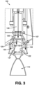
- FIGS. 1-3 illustrate an embodiment of a vortex thruster system 100 configured to efficiently and effectively generate at least three discrete thrust levels.
- the vortex thruster system 100 can include a vortex combustion chamber 102 having a proximal end 104, a distal end 106, and a sidewall 108 extending between the proximal end 104 and distal end 106.
- the vortex combustion chamber 102 may be cylindrical in shape, as shown in FIG. 1 , however, other shapes are within the scope of this disclosure.
- the proximal end 104 of the vortex combustion chamber may include a hollow dome-shape and the distal end 106 may include a converging-diverging nozzle 110 that provides a passageway through the distal end 106 of the vortex combustion chamber 102, as shown in FIG. 1 .
- the vortex thruster system 100 may include a catalyst bed 120 and at least one monopropellant valve, such as a first monopropellant valve 130 and a second monopropellant valve 140, in communication with the catalyst bed 120.
- the first monopropellant valve 130 is configured to provide a different flow rate of monopropellant 105 into the catalyst bed 120 compared to the second monopropellant valve 140.
- the first monopropellant valve 130 can provide a lower flow rate of monopropellant to allow the vortex thruster system 100 to generate a first, lower thrust level.
- the second monopropellant valve 130 can provide a higher flow rate of monopropellant to allow the vortex thruster system 100 to generate a higher, second thrust level that is greater than the first, lower thrust load.
- the catalyst bed 120 can be configured to decompose the monopropellant 105 as it flows axially through the catalyst bed 120.
- the decomposed monopropellant 107 can then be delivered into the vortex combustion chamber 102 to assist with generating thrust, as will be described in greater detail below.
- the monopropellant 105 can include a liquid hydrogen peroxide (e.g., 90% hydrogen peroxide) and the decomposed monopropellant 107 can include water vapor and gaseous oxygen.
- Other monopropellants e.g. hydrazine
- the catalyst bed 120 can include a stack of reactive and inert metallic screens.
- Other catalyst beds that can decompose monopropellants e.g. iridium-coated alumina pellet beds are within the scope of this disclosure.
- some embodiments of the vortex thruster system 100 can include an annular chamber 125 positioned around at least a part of the vortex combustion chamber 102 and in fluid communication with an outlet of the catalyst bed 120.
- the annular chamber 125 can allow the decomposed monopropellant 107 to enter the vortex combustion chamber by passing through at least one array of tangential injection ports 127 positioned along the sidewall 108 of the vortex combustion chamber 102, as shown in FIG. 3 .
- the vortex thruster system 100 can include a proximal chamber 126 for allowing the decomposed monopropellant 107 to be injected into a proximal end of the vortex combustion chamber 102 through at least one proximal injection port 129, as also shown in FIG. 3 . Any number of chambers and injectors can be included in the vortex thruster system 100 for directing and controlling the delivery of the decomposed monopropellant 107 into the vortex combustion chamber 102.
- At least one array of tangential injection ports 127 may be positioned along the sidewall 108 of the vortex combustion chamber and configured to direct the decomposed monopropellant 107 at a direction that is tangential to the circumference of the inner cylindrical surface of the sidewall 108 of the vortex combustion chamber 102.
- Such swirling can improve combustion efficiency and control hardware temperatures by shielding the vortex combustion chamber walls from high-temperature products of combustion.
- At least one proximal injection port 129 may be axially positioned along the proximal end 104 of the vortex combustion chamber 102.
- the proximal injection port 129 may be positioned approximately parallel to or along a longitudinal axis of the vortex combustion chamber 102.
- the proximal injection port 129 may be configured to deliver a portion of the decomposed monopropellant 107 into a combustion zone at or near the centerline of the vortex combustion chamber 102 (e.g., along a longitudinal axis of the vortex combustion chamber).
- the proximal injection port 129 may provide a trim function that can balance mixing and cooling functions of the vortex flow field.
- some embodiments of the vortex thruster system 100 can include a secondary propellant valve 150 configured to directly inject a secondary propellant (e.g., kerosene, such as RP-1 kerosene) directly into the vortex combustion chamber 102.
- a secondary propellant e.g., kerosene, such as RP-1 kerosene
- Other secondary propellants e.g., mixed oxides of nitrogen (MON)
- MON mixed oxides of nitrogen
- the secondary propellant can be delivered to a proximal end of the vortex combustion chamber.
- the secondary propellant can mix with high-temperature products of the decomposed monopropellant in the vortex combustion chamber to generate a desired thrust level (e.g., a high thrust mode).
- the vortex thruster system 100 can be configured to generate at least three different thrust levels that each generate discrete thrust loads or load ranges.
- the vortex thruster system 100 can generate a low thrust level (e.g., generates approximately 107N (24 lbf)), a medium thrust level (e.g., generates approximately 245N (55 lbf)), and a high thrust level (e.g., generates approximately 490N (110 lbf)).
- the low thrust level can be achieved by activating the first monopropellant valve 130 thereby delivering the monopropellant at a first, lower flow rate into the catalyst bed 120.
- the medium thrust level can be achieved by activating the second monopropellant valve 140 thereby delivering the monopropellant at a second, greater flow rate into the catalyst bed 120.
- the high thrust level can be achieved by activating the second monopropellant valve 140 as well as the secondary propellant valve 150 to allow the secondary propellant to mix and ignite with the decomposed monopropellant 107 in the vortex combustion chamber 102.
- liquid hydrogen peroxide can be injected into the catalyst bed 120 where the liquid hydrogen peroxide exothermically decomposes into gaseous oxygen and water vapor as it flows axially through the catalyst bed 120.
- the decomposed monopropellant 107 can be approximately 760C (1,400 degrees F) and can flow into the annular chamber 125 and/or proximal chamber 126 surrounding the vortex combustion chamber 102.
- the hot oxidizing gas (e.g., the decomposed monopropellant 107) can then enter the vortex combustion chamber 102 through the array of tangential injection ports 127 and/or the proximal injection port 129.
- the result of the decomposed monopropellant in the vortex combustion chamber can result in the flow of hot gas through the nozzle 110 (e.g., niobium nozzle) and the generation of monopropellant thrust (e.g., low or medium thrust levels).
- a secondary propellant e.g., kerosene
- a secondary propellant e.g., kerosene
- the products of such mixing and burning can result in combustion flow through the nozzle 110 (e.g., niobium nozzle) and generation of bipropellant thrust.
- the nozzle 110 may be coated with a silicide coating that can protect against oxidation of the niobium.
- phrases such as "at least one of” or “one or more of” may occur followed by a conjunctive list of elements or features.
- the term “and/or” may also occur in a list of two or more elements or features. Unless otherwise implicitly or explicitly contradicted by the context in which it is used, such a phrase is intended to mean any of the listed elements or features individually or any of the recited elements or features in combination with any of the other recited elements or features.
- the phrases “at least one of A and B;” “one or more of A and B;” and “A and/or B” are each intended to mean "A alone, B alone, or A and B together.”
- a similar interpretation is also intended for lists including three or more items.
- phrases “at least one of A, B, and C;” “one or more of A, B, and C;” and “A, B, and/or C” are each intended to mean “A alone, B alone, C alone, A and B together, A and C together, B and C together, or A and B and C together.”
- Use of the term “based on,” above and in the claims is intended to mean, “based at least in part on,” such that an unrecited feature or element is also permissible.
Landscapes
- Engineering & Computer Science (AREA)
- Chemical & Material Sciences (AREA)
- Combustion & Propulsion (AREA)
- Mechanical Engineering (AREA)
- General Engineering & Computer Science (AREA)
- Incineration Of Waste (AREA)
Claims (11)
- Wirbeltriebwerksystem (100), umfassend:ein Katalysatorbett (120), das so konfiguriert ist, dass es einen dem Katalysatorbett zugeführten Monotreibstoff zersetzt;ein erstes Ventil (130) zum Steuern der Zufuhr des Monotreibstoffs mit einer ersten Durchflussrate in das Katalysatorbett, um den Monotreibstoff in einen zersetzten Monotreibstoff umzuwandeln; undeine Wirbelbrennkammer (102) in Fluidverbindung mit dem Katalysatorbett und konfiguriert zum Aufnehmen des zersetzten Monotreibstoffs aus dem Katalysatorbett, wobei der zersetzte Monotreibstoff zur Erzeugung einer ersten Schubstufe beiträgt,wobei das System dadurch gekennzeichnet ist, dass die Wirbelbrennkammer (102) mindestens eine seitliche Einspritzöffnung (127) aufweist, die in der Nähe einer Seitenwand (108) der Wirbelbrennkammer angeordnet ist und so konfiguriert ist, dass sie eine erste Menge des zersetzten Monotreibstoffs in die Wirbelbrennkammer in einer Richtung abgibt, die ungefähr tangential zur Seitenwand ist, undund dass die Wirbelbrennkammer (102) eine proximale Einspritzöffnung (129) umfasst, die in der Nähe eines proximalen Endes der Wirbelbrennkammer positioniert ist und dazu ausgelegt ist, eine zweite Menge des zersetzten Monotreibstoffs in einen Mittelbereich der Wirbelbrennkammer abzugeben.
- Wirbeltriebwerkssystem (100) nach Anspruch 1, ferner umfassend ein zweites Ventil (140) zum Steuern einer zweiten Durchflussrate des Monotreibstoffs in das Katalysatorbett (120), wobei die zweite Durchflussrate größer als die erste Durchflussrate ist.
- Wirbeltriebwerk (100) nach Anspruch 2, wobei die Abgabe des Monotreibstoffs mit der zweiten Durchflussrate eine zweite Schubstufe erzeugt, die größer ist als die erste Schubstufe.
- Wirbeltriebwerk (100) nach einem der Ansprüche 1 bis 3, wobei der Monotreibstoff Wasserstoffperoxid oder Hydrazin ist.
- Wirbeltriebwerkssystem (100) nach einem der Ansprüche 1 bis 4, wobei der zersetzte Monotreibstoff Wasserdampf und Sauerstoff oder Stickstoff, Wasserstoff und Ammoniak umfasst.
- Wirbeltriebwerkssystem (100) nach einem der Ansprüche 3 bis 5, ferner umfassend ein Sekundärtreibstoffventil (150), das dazu ausgebildet ist, einen Sekundärtreibstoff, der den zersetzten Monotreibstoff enthält, in die Wirbelbrennkammer (102) zuzuführen, um eine dritte Schubstufe zu erzeugen, die größer als die zweite Schubstufe ist.
- Verfahren eines Wirbeltriebwerksystems (100), umfassend:Aktivieren eines ersten Monotreibstoffventils (130), um einen Monotreibstoff mit einer ersten Durchflussrate an ein Katalysatorbett (102) des Wirbeltriebwerksystems zuzuführen, um einen zersetzten Monotreibstoff zu bilden;Zersetzen des Monotreibstoffs im Katalysatorbett (120); undZuführen des zersetzten Monotreibstoffs in eine Wirbelbrennkammer (120) des Wirbeltriebwerksystems, um bei der Erzeugung einer ersten Schubstufe zu helfen,wobei das Zuführen des zersetzten Monotreibstoffs in die Wirbelbrennkammer das Zuführen einer ersten Menge des zersetzten Monotreibstoffs durch eine erste Einspritzöffnung (127) umfasst, die in der Nähe einer Seitenwand (108) der Wirbelbrennkammer positioniert ist und so konfiguriert ist, dass sie die erste Menge des zersetzten Monotreibstoffs in einer Richtung tangential zur Seitenwand zuführt, undwobei das Zuführen des zersetzten Monotreibstoffs in die Wirbelbrennkammer das Zuführen einer zweiten Menge des zersetzten Monotreibstoffs durch eine zweite Einspritzöffnung (129) umfasst, die in der Nähe eines proximalen Endes der Wirbelbrennkammer positioniert ist und dazu ausgelegt ist, die zweite Menge des zersetzten Monotreibstoffs in einen Mittelbereich der Wirbelbrennkammer zuzuführen.
- Verfahren nach Anspruch 7, ferner umfassend:
Aktivieren eines zweiten Monotreibstoffventils (140), um den Monotreibstoff mit einer zweiten Durchflussrate an das Katalysatorbett zuzuführen, wobei die zweite Durchflussrate größer als die erste Durchflussrate ist und wobei optional das Zuführen des Monotreibstoffs mit der zweiten Durchflussrate eine zweite Schubstufe erzeugt, der größer als die erste Schubstufe ist. - Verfahren nach einem der Ansprüche 7 bis 8, wobei der Monotreibstoff Wasserstoffperoxid oder Hydrazin ist.
- Verfahren nach einem der Ansprüche 8 bis 9, ferner umfassend:
Aktivieren eines Sekundärtreibstoffventils (150), um einen Sekundärtreibstoff, der den zersetzten Monotreibstoff enthält, in die Wirbelbrennkammer (120) zuzuführen, um eine dritte Schubstufe zu erzeugen, die größer ist als die zweite Schubstufe. - System nach Anspruch 6 oder Verfahren nach Anspruch 10, wobei der sekundäre Treibstoff Kerosin oder ein gemischtes Stickoxid ist.
Applications Claiming Priority (2)
| Application Number | Priority Date | Filing Date | Title |
|---|---|---|---|
| US16/449,229 US11572851B2 (en) | 2019-06-21 | 2019-06-21 | Reaction control vortex thruster system |
| PCT/US2020/038735 WO2020257649A1 (en) | 2019-06-21 | 2020-06-19 | Reaction control vortex thruster system |
Publications (3)
| Publication Number | Publication Date |
|---|---|
| EP3987167A1 EP3987167A1 (de) | 2022-04-27 |
| EP3987167A4 EP3987167A4 (de) | 2023-06-28 |
| EP3987167B1 true EP3987167B1 (de) | 2025-01-22 |
Family
ID=74037421
Family Applications (1)
| Application Number | Title | Priority Date | Filing Date |
|---|---|---|---|
| EP20827630.3A Active EP3987167B1 (de) | 2019-06-21 | 2020-06-19 | Wirbelantrieb mit reaktionskontrolle |
Country Status (6)
| Country | Link |
|---|---|
| US (2) | US11572851B2 (de) |
| EP (1) | EP3987167B1 (de) |
| BR (1) | BR112021025838A2 (de) |
| IL (1) | IL289076B2 (de) |
| PL (1) | PL3987167T3 (de) |
| WO (1) | WO2020257649A1 (de) |
Families Citing this family (3)
| Publication number | Priority date | Publication date | Assignee | Title |
|---|---|---|---|---|
| US11952967B2 (en) | 2021-08-19 | 2024-04-09 | Sierra Space Corporation | Liquid propellant injector for vortex hybrid rocket motor |
| WO2023177942A1 (en) * | 2022-03-17 | 2023-09-21 | Skyrocket Industries, Llc | Advanced monopropellant thruster |
| US11879414B2 (en) | 2022-04-12 | 2024-01-23 | Sierra Space Corporation | Hybrid rocket oxidizer flow control system including regression rate sensors |
Family Cites Families (87)
| Publication number | Priority date | Publication date | Assignee | Title |
|---|---|---|---|---|
| US3059429A (en) | 1958-03-25 | 1962-10-23 | Sunstrand Corp | Reaction chamber |
| US3115007A (en) | 1958-09-22 | 1963-12-24 | Phillips Petroleum Co | Self-actuating hybrid rocket motor |
| US3091520A (en) | 1958-12-19 | 1963-05-28 | North American Aviation Inc | Radial outflow catalytic pack |
| US3135703A (en) | 1959-09-21 | 1964-06-02 | Bell Aerospace Corp | Thrust chamber catalyst structure |
| FR1311203A (fr) | 1961-08-30 | 1962-12-07 | Onera (Off Nat Aerospatiale) | Perfectionnements apportés aux générateurs de gaz chauds, notamment aux moteursfusées, à propergol liquide-solide de caractère hypergolique |
| US3177657A (en) | 1961-10-02 | 1965-04-13 | Thiokol Chemical Corp | Rocket engine |
| US3158997A (en) | 1962-05-15 | 1964-12-01 | United Aircraft Corp | Tribrid rocket combustion chamber |
| US3201973A (en) | 1962-12-14 | 1965-08-24 | John E Fitzgerald | Solid propellant burning rate detector |
| FR1391928A (fr) | 1964-01-29 | 1965-03-12 | Monsieur Le Ministre Des Armee | Injecteur |
| US3368353A (en) | 1965-09-30 | 1968-02-13 | United Aircraft Corp | Automatic o/f control |
| US3426534A (en) | 1966-06-02 | 1969-02-11 | Thiokol Chemical Corp | Fuel control device |
| US3591907A (en) | 1966-10-04 | 1971-07-13 | North American Rockwell | Shrink fit fabrication method for fluid injectors |
| FR1597538A (de) | 1967-09-23 | 1970-06-29 | ||
| US3560407A (en) | 1967-11-30 | 1971-02-02 | Fmc Corp | Method of making a catalyst coated with samarium oxide |
| US3768253A (en) | 1968-05-13 | 1973-10-30 | Westinghouse Electric Corp | Vortex ring nuclear reactor |
| US3640072A (en) | 1968-07-20 | 1972-02-08 | Lutz Tilo Kayser | Rocket engine |
| US3773462A (en) | 1969-04-04 | 1973-11-20 | Stein Industrie | Heat exchanger |
| US3715888A (en) | 1969-11-26 | 1973-02-13 | Universal Oil Prod Co | Hybrid rocket |
| US3695041A (en) * | 1970-05-08 | 1972-10-03 | Rocket Research Corp | Two-stage hydrazine rocket motor |
| US3648461A (en) | 1970-05-13 | 1972-03-14 | Nasa | Solid propellent rocket motor nozzle |
| US3712059A (en) | 1970-12-03 | 1973-01-23 | Textron Inc | Reverse flow internally-cooled rocket engine |
| US3871828A (en) | 1972-10-10 | 1975-03-18 | Hughes Aircraft Co | Hydrazine gas generator |
| US3903693A (en) | 1973-03-26 | 1975-09-09 | Anthony Fox | Rocket motor housing |
| US3899815A (en) | 1973-09-28 | 1975-08-19 | Rockwell International Corp | Thermal bed screen pack |
| US4069664A (en) | 1974-01-24 | 1978-01-24 | Hughes Aircraft Company | Monopropellant thruster |
| US3956885A (en) | 1974-09-03 | 1976-05-18 | Avco Corporation | Electrothermal reactor |
| US4322946A (en) | 1975-01-22 | 1982-04-06 | Trw Inc. | Thermal thruster with superheater |
| US4840025A (en) * | 1986-10-14 | 1989-06-20 | General Electric Company | Multiple-propellant air vehicle and propulsion system |
| US4841723A (en) | 1986-10-14 | 1989-06-27 | General Electric Company | Multiple-propellant air vehicle and propulsion system |
| US4817890A (en) | 1986-10-14 | 1989-04-04 | General Electric Company | Multiple-propellant air vehicle and propulsion system |
| US4811556A (en) | 1986-10-14 | 1989-03-14 | General Electric Company | Multiple-propellant air vehicle and propulsion system |
| US5010730A (en) | 1988-02-24 | 1991-04-30 | Acurex Corporation | Gas-fed hybrid propulsion system |
| US5582001A (en) | 1989-08-24 | 1996-12-10 | Bradford; Michael D. | Hybrid rocket combustion enhancement |
| US5101623A (en) | 1990-02-06 | 1992-04-07 | Rockwell International Corporation | Rocket motor containing improved oxidizer injector |
| US5107129A (en) | 1990-06-04 | 1992-04-21 | General Dynamics Corporation/Space Systems Division | Fiber optic solid/hybrid rocket motor grain regression rate sensor |
| DE4122755A1 (de) * | 1991-07-10 | 1993-01-21 | Erno Raumfahrttechnik Gmbh | Triebwerk fuer raumflugkoerper |
| US5372070A (en) | 1992-02-10 | 1994-12-13 | Thiokol Corporation | Burn rate modification of solid propellants with bismuth trioxide |
| FR2698914B1 (fr) | 1992-12-09 | 1995-03-03 | Europ Propulsion | Moteur-fusée à ergols liquides à flux dérivé et générateur de gaz intégré. |
| US5367872A (en) | 1993-04-27 | 1994-11-29 | Thiokol Corporation | Method and apparatus for enhancing combustion efficiency of solid fuel hybrid rocket motors |
| US5529648A (en) | 1993-12-23 | 1996-06-25 | Aerodyne Research, Inc. | Heterogeneous fuel for hybrid rocket |
| JPH07310594A (ja) | 1994-05-20 | 1995-11-28 | American Rocket Co | ハイブリッドロケットモータの固体燃料グレイン |
| US5767973A (en) | 1996-02-07 | 1998-06-16 | Simmons Machine Tool Corporation | Wheelset sensing system |
| US5715675A (en) | 1994-10-21 | 1998-02-10 | Environmental Aeroscience Corp. | Hybrid rocket system and integrated motor for use therein |
| US5622046A (en) | 1995-08-28 | 1997-04-22 | The United States Of America As Represented By The Secretary Of The Army | Multiple impinging stream vortex injector |
| EP0763468B1 (de) * | 1995-09-18 | 2002-03-20 | Microcosm, Inc. | Wirtschaftliche Trägerrakete |
| US5794435A (en) | 1996-02-07 | 1998-08-18 | Lockhhed Martin Corporation | Stable-combustion oxidizer vaporizer for hybrid rockets |
| US5819526A (en) | 1996-02-23 | 1998-10-13 | Trw Inc. | Low power arcjet propellant feed system |
| DE19650411A1 (de) | 1996-12-05 | 1997-06-19 | Thomas Dr Stinnesbeck | Maximierung der Treibstoffregressionsraten von Hybridraketen |
| US6014857A (en) | 1996-12-05 | 2000-01-18 | Stinnesbeck; Thomas L. | High fuel regression hybrid rocket motor |
| US6135393A (en) * | 1997-11-25 | 2000-10-24 | Trw Inc. | Spacecraft attitude and velocity control thruster system |
| US6101808A (en) | 1998-05-29 | 2000-08-15 | Orbital Technologies Corporation | Cryogenic solid hybrid rocket engine and method of propelling a rocket |
| US6684624B2 (en) | 1998-07-22 | 2004-02-03 | The Board Of Trustees Of The Leland Stanford Junior University | High regression rate hybrid rocket propellants |
| US6601380B2 (en) | 1999-03-24 | 2003-08-05 | Orbital Technologies Corporation | Hybrid rocket engine and method of propelling a rocket |
| US6298659B1 (en) | 1999-03-24 | 2001-10-09 | Orbital Technologies Corporation | Vortex flow field and apparatus and method for producing the same |
| US6272846B1 (en) * | 1999-04-14 | 2001-08-14 | The United States Of America As Represented By The Administrator Of The National Aeronautics And Space Administration | Reduced toxicity fuel satellite propulsion system |
| TW518609B (en) | 2000-03-15 | 2003-01-21 | Hitachi Ltd | Chemical decontamination liquid decomposition device provided with catalyst tower and catalyst tower therefor |
| US6590403B1 (en) | 2000-04-17 | 2003-07-08 | Orbital Technologies Corporation | Material regression sensor |
| US6354074B1 (en) | 2000-05-24 | 2002-03-12 | Lockheed Martin Corp. | Hybrid injection thrust vector control |
| AU2003304724A1 (en) | 2002-01-16 | 2008-03-06 | W.E. Research, Llc | Methods of controlling solid propellant ignition, combustion, and extinguishment |
| US6860099B1 (en) | 2003-01-09 | 2005-03-01 | The United States Of America As Represented By The Administrator Of The National Aeronautics And Space Administration | Liquid propellant tracing impingement injector |
| US6834494B2 (en) | 2003-04-01 | 2004-12-28 | The Boeing Company | Design and assembly of a catalyst bed gas generator for the catalytic decomposition of high concentration hydrogen peroxide propellants and the catalytic combustion of hydrocarbon/air mixtures |
| US7257939B2 (en) | 2003-08-15 | 2007-08-21 | United States Of America As Represented By The Secretary Of The Army | Sliding-action magneto-mechanical injector throttling device |
| IL159248A (en) | 2003-12-08 | 2011-10-31 | Aharon Oren | Impulse motor with increased electro-thermal impulse |
| US20070144140A1 (en) | 2005-12-22 | 2007-06-28 | Sarigul-Klijn Martinus M | High propellant mass fraction hybrid rocket propulsion |
| US7452513B2 (en) | 2006-09-02 | 2008-11-18 | Igor Matveev | Triple helical flow vortex reactor |
| WO2008153549A2 (en) * | 2006-11-13 | 2008-12-18 | Space Propulsion Group, Inc. | Mixtures of oxides of nitrogen and oxygen as oxidizers for propulsion, gas generation and power generation applications |
| US7762058B2 (en) * | 2007-04-17 | 2010-07-27 | Pratt & Whitney Rocketdyne, Inc. | Ultra-compact, high performance aerovortical rocket thruster |
| US20120060464A1 (en) | 2007-07-24 | 2012-03-15 | James Robert Grote | Systems, methods and apparatus for propulsion |
| US8707676B2 (en) | 2008-02-28 | 2014-04-29 | The Aerospace Corporation | Radial flow rapid prototyping rocket motors |
| US8225507B2 (en) | 2008-02-28 | 2012-07-24 | The Aerospace Corporation | Stereolithographic rocket motor manufacturing method |
| US9038368B2 (en) | 2011-08-01 | 2015-05-26 | The Aerospace Corporation | Systems, methods, and apparatus for providing a multi-fuel hybrid rocket motor |
| US20130042596A1 (en) | 2011-08-02 | 2013-02-21 | The Aerospace Corporation | Systems and Methods for Fabricating Hybrid Rocket Fuel Motor Fuel Grains |
| US20130074472A1 (en) | 2011-09-24 | 2013-03-28 | Robert J. Jensen | Injector having multiple impingement lengths |
| US20140026537A1 (en) | 2012-07-30 | 2014-01-30 | Utah State University | Multiple Use Hybrid Rocket Motor |
| US20140123654A1 (en) | 2012-11-07 | 2014-05-08 | General Electric Companpy | Fuel metering valve system |
| CN105164471B (zh) | 2013-03-13 | 2017-09-08 | 工业涡轮(英国)有限公司 | 贫方位角火焰燃烧器 |
| TWI504538B (zh) | 2013-05-31 | 2015-10-21 | Nat Applied Res Laboratories | 雙旋流混合火箭引擎 |
| CN105020050B (zh) | 2015-06-03 | 2019-07-09 | 中国人民解放军战略支援部队航天工程大学 | 采用射流对撞燃烧方式的在线可调式燃气发生器 |
| US10781773B2 (en) | 2015-11-04 | 2020-09-22 | Northrop Grumman Innovation Systems, Inc. | Solid rocket motors including flight termination systems, and related multi-stage solid rocket motor assemblies and methods |
| US20180156159A1 (en) | 2016-07-12 | 2018-06-07 | Additive Rocket Corporation | Regenerative hybrid rocket motor |
| US11124464B2 (en) | 2016-09-09 | 2021-09-21 | Terves, Llc | High density hybrid rocket motor |
| US20180334996A1 (en) | 2017-05-21 | 2018-11-22 | Streamline Automation Llc | Hybrid Rocket Motor |
| BR112021003328A8 (pt) | 2018-08-23 | 2023-02-07 | Rocket Crafters Propulsion Llc | Sistema de injeção de campo de fluxo em vórtex com alta taxa de regressão e controle de vazão linear em um motor foguete híbrido |
| US11661907B2 (en) | 2018-10-11 | 2023-05-30 | Sierra Space Corporation | Vortex hybrid rocket motor |
| TWI669448B (zh) | 2019-01-04 | 2019-08-21 | 晉陞太空科技股份有限公司 | 發動機的氧化劑注入器 |
| US12060853B2 (en) | 2019-01-30 | 2024-08-13 | Laboratoire Reaction Dynamics Inc. | Rocket engine with integrated oxidizer catalyst in manifold and injector assembly |
| CN110118136B (zh) | 2019-04-29 | 2021-10-08 | 南京理工大学 | 推力可调的过氧化氢单组元推力器 |
-
2019
- 2019-06-21 US US16/449,229 patent/US11572851B2/en active Active
-
2020
- 2020-06-19 BR BR112021025838A patent/BR112021025838A2/pt not_active Application Discontinuation
- 2020-06-19 EP EP20827630.3A patent/EP3987167B1/de active Active
- 2020-06-19 IL IL289076A patent/IL289076B2/en unknown
- 2020-06-19 WO PCT/US2020/038735 patent/WO2020257649A1/en not_active Ceased
- 2020-06-19 PL PL20827630.3T patent/PL3987167T3/pl unknown
-
2023
- 2023-01-06 US US18/094,300 patent/US11927152B2/en active Active
Also Published As
| Publication number | Publication date |
|---|---|
| PL3987167T3 (pl) | 2025-05-19 |
| US20230160359A1 (en) | 2023-05-25 |
| EP3987167A1 (de) | 2022-04-27 |
| IL289076B1 (en) | 2025-01-01 |
| US20200400103A1 (en) | 2020-12-24 |
| WO2020257649A1 (en) | 2020-12-24 |
| IL289076A (en) | 2022-02-01 |
| US11927152B2 (en) | 2024-03-12 |
| IL289076B2 (en) | 2025-05-01 |
| EP3987167A4 (de) | 2023-06-28 |
| US11572851B2 (en) | 2023-02-07 |
| BR112021025838A2 (pt) | 2022-04-26 |
Similar Documents
| Publication | Publication Date | Title |
|---|---|---|
| US11927152B2 (en) | Reaction control vortex thruster system | |
| US6601380B2 (en) | Hybrid rocket engine and method of propelling a rocket | |
| EP0620895B1 (de) | Antriebs- und energieversorgungssystem für einen satelliten | |
| US6588199B2 (en) | High performance rocket engine having a stepped expansion combustion chamber and method of making the same | |
| US8776526B2 (en) | Motor with solid fuel installed within combustion chamber and vortex generator installed on inner wall of combustion chamber | |
| EP3864278B1 (de) | Wirbelhybridraketenmotor | |
| US11480136B1 (en) | Monopropellant continuous detonation engines | |
| JP2022553637A (ja) | 宇宙船用ハイブリッド推進装置 | |
| US3423943A (en) | Hybrid rocket motor | |
| US10920714B2 (en) | Stable hybrid rocket technology | |
| US20220120240A1 (en) | Vortex thruster system including catalyst bed with screen assembly | |
| JP4100518B2 (ja) | ピントル噴射器 | |
| US20240125287A1 (en) | Monopropellant continuous detonation engines | |
| CN113039392A (zh) | 旋流式预燃器系统和方法 | |
| US11952967B2 (en) | Liquid propellant injector for vortex hybrid rocket motor | |
| KR102793795B1 (ko) | 고성능 이원추진제 엔진 | |
| WO2024239046A1 (en) | A manifold for a rocket engine | |
| AU2023357936A1 (en) | Thruster for orbital maneuvers, propulsion system for orbital maneuvers and orbital transport vehicle | |
| HK40050939B (en) | Swirl preburner system and method | |
| Conrad | Exploring in aerospace rocketry. 7-Liquid propellant rocket systems | |
| JPH0354351A (ja) | 2段ロケット燃焼器 |
Legal Events
| Date | Code | Title | Description |
|---|---|---|---|
| STAA | Information on the status of an ep patent application or granted ep patent |
Free format text: STATUS: THE INTERNATIONAL PUBLICATION HAS BEEN MADE |
|
| PUAI | Public reference made under article 153(3) epc to a published international application that has entered the european phase |
Free format text: ORIGINAL CODE: 0009012 |
|
| STAA | Information on the status of an ep patent application or granted ep patent |
Free format text: STATUS: REQUEST FOR EXAMINATION WAS MADE |
|
| 17P | Request for examination filed |
Effective date: 20220117 |
|
| AK | Designated contracting states |
Kind code of ref document: A1 Designated state(s): AL AT BE BG CH CY CZ DE DK EE ES FI FR GB GR HR HU IE IS IT LI LT LU LV MC MK MT NL NO PL PT RO RS SE SI SK SM TR |
|
| DAV | Request for validation of the european patent (deleted) | ||
| DAX | Request for extension of the european patent (deleted) | ||
| A4 | Supplementary search report drawn up and despatched |
Effective date: 20230530 |
|
| RIC1 | Information provided on ipc code assigned before grant |
Ipc: F02K 9/56 20060101ALI20230523BHEP Ipc: F02K 9/52 20060101ALI20230523BHEP Ipc: B64G 1/40 20060101ALI20230523BHEP Ipc: B64G 1/26 20060101ALI20230523BHEP Ipc: F02K 9/68 20060101AFI20230523BHEP |
|
| REG | Reference to a national code |
Ref country code: DE Ref legal event code: R079 Free format text: PREVIOUS MAIN CLASS: F02K0009680000 Ipc: F02K0009440000 Ref document number: 602020045261 Country of ref document: DE |
|
| RIC1 | Information provided on ipc code assigned before grant |
Ipc: F02K 9/42 20060101ALI20240718BHEP Ipc: B64G 1/26 20060101ALI20240718BHEP Ipc: B64G 1/40 20060101ALI20240718BHEP Ipc: F02K 9/72 20060101ALI20240718BHEP Ipc: F02K 9/58 20060101ALI20240718BHEP Ipc: F02K 9/52 20060101ALI20240718BHEP Ipc: F02K 9/56 20060101ALI20240718BHEP Ipc: F02K 9/68 20060101ALI20240718BHEP Ipc: F02K 9/44 20060101AFI20240718BHEP |
|
| GRAP | Despatch of communication of intention to grant a patent |
Free format text: ORIGINAL CODE: EPIDOSNIGR1 |
|
| STAA | Information on the status of an ep patent application or granted ep patent |
Free format text: STATUS: GRANT OF PATENT IS INTENDED |
|
| INTG | Intention to grant announced |
Effective date: 20240903 |
|
| GRAS | Grant fee paid |
Free format text: ORIGINAL CODE: EPIDOSNIGR3 |
|
| GRAA | (expected) grant |
Free format text: ORIGINAL CODE: 0009210 |
|
| STAA | Information on the status of an ep patent application or granted ep patent |
Free format text: STATUS: THE PATENT HAS BEEN GRANTED |
|
| AK | Designated contracting states |
Kind code of ref document: B1 Designated state(s): AL AT BE BG CH CY CZ DE DK EE ES FI FR GB GR HR HU IE IS IT LI LT LU LV MC MK MT NL NO PL PT RO RS SE SI SK SM TR |
|
| REG | Reference to a national code |
Ref country code: GB Ref legal event code: FG4D |
|
| REG | Reference to a national code |
Ref country code: CH Ref legal event code: EP |
|
| REG | Reference to a national code |
Ref country code: IE Ref legal event code: FG4D |
|
| REG | Reference to a national code |
Ref country code: DE Ref legal event code: R096 Ref document number: 602020045261 Country of ref document: DE |
|
| REG | Reference to a national code |
Ref country code: NL Ref legal event code: FP |
|
| P01 | Opt-out of the competence of the unified patent court (upc) registered |
Free format text: CASE NUMBER: APP_24622/2025 Effective date: 20250522 |
|
| PG25 | Lapsed in a contracting state [announced via postgrant information from national office to epo] |
Ref country code: RS Free format text: LAPSE BECAUSE OF FAILURE TO SUBMIT A TRANSLATION OF THE DESCRIPTION OR TO PAY THE FEE WITHIN THE PRESCRIBED TIME-LIMIT Effective date: 20250422 |
|
| PG25 | Lapsed in a contracting state [announced via postgrant information from national office to epo] |
Ref country code: FI Free format text: LAPSE BECAUSE OF FAILURE TO SUBMIT A TRANSLATION OF THE DESCRIPTION OR TO PAY THE FEE WITHIN THE PRESCRIBED TIME-LIMIT Effective date: 20250122 |
|
| PGFP | Annual fee paid to national office [announced via postgrant information from national office to epo] |
Ref country code: PL Payment date: 20250602 Year of fee payment: 6 Ref country code: DE Payment date: 20250627 Year of fee payment: 6 |
|
| PG25 | Lapsed in a contracting state [announced via postgrant information from national office to epo] |
Ref country code: ES Free format text: LAPSE BECAUSE OF FAILURE TO SUBMIT A TRANSLATION OF THE DESCRIPTION OR TO PAY THE FEE WITHIN THE PRESCRIBED TIME-LIMIT Effective date: 20250122 |
|
| PGFP | Annual fee paid to national office [announced via postgrant information from national office to epo] |
Ref country code: GB Payment date: 20250627 Year of fee payment: 6 |
|
| REG | Reference to a national code |
Ref country code: LT Ref legal event code: MG9D |
|
| PG25 | Lapsed in a contracting state [announced via postgrant information from national office to epo] |
Ref country code: IS Free format text: LAPSE BECAUSE OF FAILURE TO SUBMIT A TRANSLATION OF THE DESCRIPTION OR TO PAY THE FEE WITHIN THE PRESCRIBED TIME-LIMIT Effective date: 20250522 |
|
| PGFP | Annual fee paid to national office [announced via postgrant information from national office to epo] |
Ref country code: NO Payment date: 20250627 Year of fee payment: 6 |
|
| PGFP | Annual fee paid to national office [announced via postgrant information from national office to epo] |
Ref country code: NL Payment date: 20250626 Year of fee payment: 6 |
|
| REG | Reference to a national code |
Ref country code: AT Ref legal event code: MK05 Ref document number: 1761636 Country of ref document: AT Kind code of ref document: T Effective date: 20250122 |
|
| PG25 | Lapsed in a contracting state [announced via postgrant information from national office to epo] |
Ref country code: HR Free format text: LAPSE BECAUSE OF FAILURE TO SUBMIT A TRANSLATION OF THE DESCRIPTION OR TO PAY THE FEE WITHIN THE PRESCRIBED TIME-LIMIT Effective date: 20250122 |
|
| PG25 | Lapsed in a contracting state [announced via postgrant information from national office to epo] |
Ref country code: PT Free format text: LAPSE BECAUSE OF FAILURE TO SUBMIT A TRANSLATION OF THE DESCRIPTION OR TO PAY THE FEE WITHIN THE PRESCRIBED TIME-LIMIT Effective date: 20250522 Ref country code: LV Free format text: LAPSE BECAUSE OF FAILURE TO SUBMIT A TRANSLATION OF THE DESCRIPTION OR TO PAY THE FEE WITHIN THE PRESCRIBED TIME-LIMIT Effective date: 20250122 |
|
| PGFP | Annual fee paid to national office [announced via postgrant information from national office to epo] |
Ref country code: FR Payment date: 20250625 Year of fee payment: 6 |
|
| PG25 | Lapsed in a contracting state [announced via postgrant information from national office to epo] |
Ref country code: BG Free format text: LAPSE BECAUSE OF FAILURE TO SUBMIT A TRANSLATION OF THE DESCRIPTION OR TO PAY THE FEE WITHIN THE PRESCRIBED TIME-LIMIT Effective date: 20250122 Ref country code: GR Free format text: LAPSE BECAUSE OF FAILURE TO SUBMIT A TRANSLATION OF THE DESCRIPTION OR TO PAY THE FEE WITHIN THE PRESCRIBED TIME-LIMIT Effective date: 20250423 |
|
| PG25 | Lapsed in a contracting state [announced via postgrant information from national office to epo] |
Ref country code: AT Free format text: LAPSE BECAUSE OF FAILURE TO SUBMIT A TRANSLATION OF THE DESCRIPTION OR TO PAY THE FEE WITHIN THE PRESCRIBED TIME-LIMIT Effective date: 20250122 |
|
| PG25 | Lapsed in a contracting state [announced via postgrant information from national office to epo] |
Ref country code: SE Free format text: LAPSE BECAUSE OF FAILURE TO SUBMIT A TRANSLATION OF THE DESCRIPTION OR TO PAY THE FEE WITHIN THE PRESCRIBED TIME-LIMIT Effective date: 20250122 |
|
| PG25 | Lapsed in a contracting state [announced via postgrant information from national office to epo] |
Ref country code: SM Free format text: LAPSE BECAUSE OF FAILURE TO SUBMIT A TRANSLATION OF THE DESCRIPTION OR TO PAY THE FEE WITHIN THE PRESCRIBED TIME-LIMIT Effective date: 20250122 |
|
| PG25 | Lapsed in a contracting state [announced via postgrant information from national office to epo] |
Ref country code: DK Free format text: LAPSE BECAUSE OF FAILURE TO SUBMIT A TRANSLATION OF THE DESCRIPTION OR TO PAY THE FEE WITHIN THE PRESCRIBED TIME-LIMIT Effective date: 20250122 |
|
| PG25 | Lapsed in a contracting state [announced via postgrant information from national office to epo] |
Ref country code: IT Free format text: LAPSE BECAUSE OF FAILURE TO SUBMIT A TRANSLATION OF THE DESCRIPTION OR TO PAY THE FEE WITHIN THE PRESCRIBED TIME-LIMIT Effective date: 20250122 |
|
| PG25 | Lapsed in a contracting state [announced via postgrant information from national office to epo] |
Ref country code: CZ Free format text: LAPSE BECAUSE OF FAILURE TO SUBMIT A TRANSLATION OF THE DESCRIPTION OR TO PAY THE FEE WITHIN THE PRESCRIBED TIME-LIMIT Effective date: 20250122 Ref country code: EE Free format text: LAPSE BECAUSE OF FAILURE TO SUBMIT A TRANSLATION OF THE DESCRIPTION OR TO PAY THE FEE WITHIN THE PRESCRIBED TIME-LIMIT Effective date: 20250122 |
|
| REG | Reference to a national code |
Ref country code: DE Ref legal event code: R097 Ref document number: 602020045261 Country of ref document: DE |
|
| PG25 | Lapsed in a contracting state [announced via postgrant information from national office to epo] |
Ref country code: RO Free format text: LAPSE BECAUSE OF FAILURE TO SUBMIT A TRANSLATION OF THE DESCRIPTION OR TO PAY THE FEE WITHIN THE PRESCRIBED TIME-LIMIT Effective date: 20250122 |
|
| PG25 | Lapsed in a contracting state [announced via postgrant information from national office to epo] |
Ref country code: SK Free format text: LAPSE BECAUSE OF FAILURE TO SUBMIT A TRANSLATION OF THE DESCRIPTION OR TO PAY THE FEE WITHIN THE PRESCRIBED TIME-LIMIT Effective date: 20250122 |
|
| PLBE | No opposition filed within time limit |
Free format text: ORIGINAL CODE: 0009261 |
|
| STAA | Information on the status of an ep patent application or granted ep patent |
Free format text: STATUS: NO OPPOSITION FILED WITHIN TIME LIMIT |
|
| REG | Reference to a national code |
Ref country code: CH Ref legal event code: L10 Free format text: ST27 STATUS EVENT CODE: U-0-0-L10-L00 (AS PROVIDED BY THE NATIONAL OFFICE) Effective date: 20251203 |
|
| 26N | No opposition filed |
Effective date: 20251023 |
|
| REG | Reference to a national code |
Ref country code: CH Ref legal event code: H13 Free format text: ST27 STATUS EVENT CODE: U-0-0-H10-H13 (AS PROVIDED BY THE NATIONAL OFFICE) Effective date: 20260127 |
|
| PG25 | Lapsed in a contracting state [announced via postgrant information from national office to epo] |
Ref country code: MC Free format text: LAPSE BECAUSE OF FAILURE TO SUBMIT A TRANSLATION OF THE DESCRIPTION OR TO PAY THE FEE WITHIN THE PRESCRIBED TIME-LIMIT Effective date: 20250122 |
|
| PG25 | Lapsed in a contracting state [announced via postgrant information from national office to epo] |
Ref country code: LU Free format text: LAPSE BECAUSE OF NON-PAYMENT OF DUE FEES Effective date: 20250619 |
|
| REG | Reference to a national code |
Ref country code: BE Ref legal event code: MM Effective date: 20250630 |
|
| PG25 | Lapsed in a contracting state [announced via postgrant information from national office to epo] |
Ref country code: IE Free format text: LAPSE BECAUSE OF NON-PAYMENT OF DUE FEES Effective date: 20250619 |
|
| PG25 | Lapsed in a contracting state [announced via postgrant information from national office to epo] |
Ref country code: BE Free format text: LAPSE BECAUSE OF NON-PAYMENT OF DUE FEES Effective date: 20250630 |
|
| PG25 | Lapsed in a contracting state [announced via postgrant information from national office to epo] |
Ref country code: CH Free format text: LAPSE BECAUSE OF NON-PAYMENT OF DUE FEES Effective date: 20250630 |