EP3985660A1 - Ultrasonic speaker - Google Patents
Ultrasonic speaker Download PDFInfo
- Publication number
- EP3985660A1 EP3985660A1 EP21200101.0A EP21200101A EP3985660A1 EP 3985660 A1 EP3985660 A1 EP 3985660A1 EP 21200101 A EP21200101 A EP 21200101A EP 3985660 A1 EP3985660 A1 EP 3985660A1
- Authority
- EP
- European Patent Office
- Prior art keywords
- substrate
- protrusions
- case
- ultrasonic speaker
- lower stages
- Prior art date
- Legal status (The legal status is an assumption and is not a legal conclusion. Google has not performed a legal analysis and makes no representation as to the accuracy of the status listed.)
- Withdrawn
Links
Images


Classifications
-
- H—ELECTRICITY
- H04—ELECTRIC COMMUNICATION TECHNIQUE
- H04R—LOUDSPEAKERS, MICROPHONES, GRAMOPHONE PICK-UPS OR LIKE ACOUSTIC ELECTROMECHANICAL TRANSDUCERS; ELECTRIC HEARING AIDS; PUBLIC ADDRESS SYSTEMS
- H04R1/00—Details of transducers, loudspeakers or microphones
- H04R1/20—Arrangements for obtaining desired frequency or directional characteristics
- H04R1/32—Arrangements for obtaining desired frequency or directional characteristics for obtaining desired directional characteristic only
- H04R1/323—Arrangements for obtaining desired frequency or directional characteristics for obtaining desired directional characteristic only for loudspeakers
-
- G—PHYSICS
- G10—MUSICAL INSTRUMENTS; ACOUSTICS
- G10K—SOUND-PRODUCING DEVICES; METHODS OR DEVICES FOR PROTECTING AGAINST, OR FOR DAMPING, NOISE OR OTHER ACOUSTIC WAVES IN GENERAL; ACOUSTICS NOT OTHERWISE PROVIDED FOR
- G10K9/00—Devices in which sound is produced by vibrating a diaphragm or analogous element, e.g. fog horns, vehicle hooters or buzzers
- G10K9/12—Devices in which sound is produced by vibrating a diaphragm or analogous element, e.g. fog horns, vehicle hooters or buzzers electrically operated
- G10K9/122—Devices in which sound is produced by vibrating a diaphragm or analogous element, e.g. fog horns, vehicle hooters or buzzers electrically operated using piezoelectric driving means
-
- H—ELECTRICITY
- H04—ELECTRIC COMMUNICATION TECHNIQUE
- H04R—LOUDSPEAKERS, MICROPHONES, GRAMOPHONE PICK-UPS OR LIKE ACOUSTIC ELECTROMECHANICAL TRANSDUCERS; ELECTRIC HEARING AIDS; PUBLIC ADDRESS SYSTEMS
- H04R1/00—Details of transducers, loudspeakers or microphones
- H04R1/02—Casings; Cabinets ; Supports therefor; Mountings therein
- H04R1/021—Casings; Cabinets ; Supports therefor; Mountings therein incorporating only one transducer
-
- G—PHYSICS
- G10—MUSICAL INSTRUMENTS; ACOUSTICS
- G10K—SOUND-PRODUCING DEVICES; METHODS OR DEVICES FOR PROTECTING AGAINST, OR FOR DAMPING, NOISE OR OTHER ACOUSTIC WAVES IN GENERAL; ACOUSTICS NOT OTHERWISE PROVIDED FOR
- G10K15/00—Acoustics not otherwise provided for
- G10K15/02—Synthesis of acoustic waves
-
- H—ELECTRICITY
- H04—ELECTRIC COMMUNICATION TECHNIQUE
- H04R—LOUDSPEAKERS, MICROPHONES, GRAMOPHONE PICK-UPS OR LIKE ACOUSTIC ELECTROMECHANICAL TRANSDUCERS; ELECTRIC HEARING AIDS; PUBLIC ADDRESS SYSTEMS
- H04R2217/00—Details of magnetostrictive, piezoelectric, or electrostrictive transducers covered by H04R15/00 or H04R17/00 but not provided for in any of their subgroups
- H04R2217/03—Parametric transducers where sound is generated or captured by the acoustic demodulation of amplitude modulated ultrasonic waves
Definitions
- the present invention relates to an ultrasonic speaker suitable for a parametric speaker.
- Japanese Registered Patent No. 6707242 and the like disclose related art examples of an array type parametric speaker using ultrasonic speakers.
- Some of the related art examples have adopted a structure in which a case is provided with a step so that the inner diameter of the bottom surface of the case is smaller than the inner diameter of the top surface (opening portion) of the case, and a substrate is placed on the top surface of the step.
- the present invention has an object to provide an ultrasonic speaker capable of increasing an effective vibration area as compared with the size of a substrate and improving the characteristics of a parametric speaker.
- An ultrasonic speaker of the present invention comprises a case that has an opened top surface and includes a plurality of protrusions protruding inward on an inner side surface of the case, a piezoelectric element fixed to a bottom surface in the case, and a substrate that is inserted in the case and placed on upper surfaces of the plurality of protrusions.
- the effective vibration area can be increased as compared with the size of the substrate, and the characteristics of the parametric speaker can be improved.
- an ultrasonic speaker 1 of the present embodiment comprises a case 11 having a cylindrical shape that has an opened top surface and includes a plurality of protrusions 111 protruding inward on an inner side surface of the case, a disc-shaped piezoelectric element 12 fixed to a bottom surface in the case 11, a disc-shaped sponge piece 13 that is accommodated in the case 11 and arranged so as to cover the piezoelectric element 12, a disc-shaped substrate 14 that is inserted in the case 11 and placed on upper surfaces of the plurality of protrusions 111, two pins 15 that are connected to the substrate 14 and extend upward, and a lead wire (not shown) for connecting the pins 15 and the piezoelectric element 12.
- the substrate 14 is, for example, a PCB. Note that the top surface (opened surface) of the case 11 is hermetically sealed with a sealing material (not shown).
- the protrusions 111 are arranged on both upper and lower stages of the inner side surface of the case 11, which correspond to two types of reference depths on the inner side surface of the case 11.
- the substrate 14 includes notches 141 at positions where the substrate 14 passes through the protrusions 111 on the upper stage, and is placed on the upper surfaces of the protrusions 111 on the lower stage as shown in FIG. 5 .
- the protrusions 111 on the upper and lower stages are arranged at positions where the substrate 14 is held between the protrusions 111 on the upper and lower stages by inserting the substrate 14 into the case 11 while the notches 141 are aligned with the protrusions 111 on the upper stage to allow the substrate 14 to pass through the protrusions 111 on the upper stage, and then rotating the substrate 14 by a predetermined angle with a vertical direction set as a rotation axis (see FIG. 5 ).
- a total of three protrusions 111 on the upper stage are provided to be arranged at angular intervals of 120°
- a total of three protrusions 111 on the lower stage are provided to be likewise arranged at angular intervals of 120° and further rotationally shifted by 60° from the three protrusions 111 on the upper stage respectively.
- the substrate 14 has a total of three notches 141 arranged at angular intervals of 120°.
- the substrate 14 is passed through the protrusions 111 on the upper stage, and then rotated by about 30° with the vertical direction set as the rotation axis, whereby the substrate 14 can be fixed. Note that the distance in the vertical direction between the lower surface of each protrusion 111 on the upper stage and the upper surface of each protrusion 111 on the lower stage is substantially equal to the thickness of the substrate 14.
- the ultrasonic speaker 1 of the present embodiment is configured so that the protrusions 111 protruding inward are provided in the case 11, and the substrate 14 is placed on the upper surfaces of the protrusions 111. Therefore, the inner diameter of the bottom surface of the case can be made equal to the inner diameter of the top surface of the case, so that the gap g occurring between adjacent ultrasonic speakers can be almost eliminated (the adjacent pitch can be reduced), the effective vibration area can be increased, and the characteristics of the parametric speaker can be improved.
- the protrusions 111 on the upper and lower stages are arranged at positions where the substrate 14 is held between the protrusions 111 on the upper and lower stages by passing the substrate 14 through the protrusions 111 on the upper stage and then rotating the substrate 14 by a predetermined angle with the vertical direction set as the rotation axis.
- the substrate 14 can be fixed by interposing the substrate 14 between the protrusions 111 on the upper and lower stages, and a step of soldering lead wires to the substrate 14 can be easily performed (in the related art, a substrate is simply placed on the pedestal of a case, so that when a piezoelectric element is soldered and connected to the substrate with lead wires, it is necessary to hold the substrate so that the substrate does not move). Further, this structure also contributes to holding the substrate 14 horizontally. For example, even when the upper surface of the substrate 14 is filled with a sealing material (silicon) or the like in order to improve the characteristics, it is possible to prevent the substrate 14 from tilting due to the weight of the sealing material (silicon).
- a sealing material silicon
Landscapes
- Physics & Mathematics (AREA)
- Engineering & Computer Science (AREA)
- Acoustics & Sound (AREA)
- Signal Processing (AREA)
- Health & Medical Sciences (AREA)
- Otolaryngology (AREA)
- Multimedia (AREA)
- Circuit For Audible Band Transducer (AREA)
- Transducers For Ultrasonic Waves (AREA)
Abstract
Description
- The present invention relates to an ultrasonic speaker suitable for a parametric speaker.
- For example,
Japanese Registered Patent No. 6707242 - Some of the related art examples have adopted a structure in which a case is provided with a step so that the inner diameter of the bottom surface of the case is smaller than the inner diameter of the top surface (opening portion) of the case, and a substrate is placed on the top surface of the step.
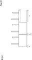
- In the case where this structure is adopted, even when ultrasonic speakers are arranged to be spread all over as densely as possible as shown in
FIG. 1 , a gap g occurs between adjacent ultrasonic speakers, and the gap g is equal to a value larger than the double (2d) of the step d (g>2d). As a result, the size (outer diameter D) of the bottom surface of the case becomes smaller than the size (outer diameter L) of the substrate, which has caused a problem that an effective vibration area cannot be gained. - Therefore, the present invention has an object to provide an ultrasonic speaker capable of increasing an effective vibration area as compared with the size of a substrate and improving the characteristics of a parametric speaker.
- An ultrasonic speaker of the present invention comprises a case that has an opened top surface and includes a plurality of protrusions protruding inward on an inner side surface of the case, a piezoelectric element fixed to a bottom surface in the case, and a substrate that is inserted in the case and placed on upper surfaces of the plurality of protrusions.
- According to the ultrasonic speaker of the present invention, the effective vibration area can be increased as compared with the size of the substrate, and the characteristics of the parametric speaker can be improved.
-
-
FIG. 1 is a diagram showing an example of a conventional ultrasonic speaker; -
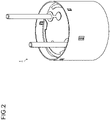
FIG. 2 is a perspective view of an ultrasonic speaker of a first embodiment; -
FIG. 3 is an exploded perspective view of the ultrasonic speaker of the first embodiment; -
FIG. 4 is a plan view of the ultrasonic speaker of the first embodiment; and -
FIG. 5 is a cross-sectional view of the ultrasonic speaker of the first embodiment. - Hereinafter, an embodiment of the present invention will be described in detail. Components having the same functions are designated by the same reference numerals, and duplicative description thereon will be omitted.
- Hereinafter, the structure of an ultrasonic speaker of a first embodiment will be described with reference to
FIGS. 2 to 5 . As shown inFIG. 3 , anultrasonic speaker 1 of the present embodiment comprises acase 11 having a cylindrical shape that has an opened top surface and includes a plurality ofprotrusions 111 protruding inward on an inner side surface of the case, a disc-shapedpiezoelectric element 12 fixed to a bottom surface in thecase 11, a disc-shaped sponge piece 13 that is accommodated in thecase 11 and arranged so as to cover thepiezoelectric element 12, a disc-shaped substrate 14 that is inserted in thecase 11 and placed on upper surfaces of the plurality ofprotrusions 111, twopins 15 that are connected to thesubstrate 14 and extend upward, and a lead wire (not shown) for connecting thepins 15 and thepiezoelectric element 12. Thesubstrate 14 is, for example, a PCB. Note that the top surface (opened surface) of thecase 11 is hermetically sealed with a sealing material (not shown). The sealing material may be, for example, a silicon-based material. - As shown in the cross-sectional view of
FIG. 5 (a cutting line is shown inFIG. 4 ), theprotrusions 111 are arranged on both upper and lower stages of the inner side surface of thecase 11, which correspond to two types of reference depths on the inner side surface of thecase 11. As shown inFIG. 3 , thesubstrate 14 includesnotches 141 at positions where thesubstrate 14 passes through theprotrusions 111 on the upper stage, and is placed on the upper surfaces of theprotrusions 111 on the lower stage as shown inFIG. 5 . - It is preferable to arrange the
protrusions 111 on the upper and lower stages at positions where thesubstrate 14 is held between theprotrusions 111 on the upper and lower stages by inserting thesubstrate 14 into thecase 11 while thenotches 141 are aligned with theprotrusions 111 on the upper stage to allow thesubstrate 14 to pass through theprotrusions 111 on the upper stage, and then rotating thesubstrate 14 by a predetermined angle with a vertical direction set as a rotation axis (seeFIG. 5 ). - For example, a total of three
protrusions 111 on the upper stage are provided to be arranged at angular intervals of 120°, and a total of threeprotrusions 111 on the lower stage are provided to be likewise arranged at angular intervals of 120° and further rotationally shifted by 60° from the threeprotrusions 111 on the upper stage respectively. Thesubstrate 14 has a total of threenotches 141 arranged at angular intervals of 120°. Thesubstrate 14 is passed through theprotrusions 111 on the upper stage, and then rotated by about 30° with the vertical direction set as the rotation axis, whereby thesubstrate 14 can be fixed. Note that the distance in the vertical direction between the lower surface of eachprotrusion 111 on the upper stage and the upper surface of eachprotrusion 111 on the lower stage is substantially equal to the thickness of thesubstrate 14. - The
ultrasonic speaker 1 of the present embodiment is configured so that theprotrusions 111 protruding inward are provided in thecase 11, and thesubstrate 14 is placed on the upper surfaces of theprotrusions 111. Therefore, the inner diameter of the bottom surface of the case can be made equal to the inner diameter of the top surface of the case, so that the gap g occurring between adjacent ultrasonic speakers can be almost eliminated (the adjacent pitch can be reduced), the effective vibration area can be increased, and the characteristics of the parametric speaker can be improved. - According to the
ultrasonic speaker 1 of the present embodiment, theprotrusions 111 on the upper and lower stages are arranged at positions where thesubstrate 14 is held between theprotrusions 111 on the upper and lower stages by passing thesubstrate 14 through theprotrusions 111 on the upper stage and then rotating thesubstrate 14 by a predetermined angle with the vertical direction set as the rotation axis. Therefore, thesubstrate 14 can be fixed by interposing thesubstrate 14 between theprotrusions 111 on the upper and lower stages, and a step of soldering lead wires to thesubstrate 14 can be easily performed (in the related art, a substrate is simply placed on the pedestal of a case, so that when a piezoelectric element is soldered and connected to the substrate with lead wires, it is necessary to hold the substrate so that the substrate does not move). Further, this structure also contributes to holding thesubstrate 14 horizontally. For example, even when the upper surface of thesubstrate 14 is filled with a sealing material (silicon) or the like in order to improve the characteristics, it is possible to prevent thesubstrate 14 from tilting due to the weight of the sealing material (silicon).
Claims (3)
- An ultrasonic speaker comprising:a case that has an opened top surface and includes a plurality of protrusions protruding inward on an inner side surface of the case;a piezoelectric element fixed to a bottom surface in the case; anda substrate that is inserted in the case and placed on upper surfaces of the plurality of protrusions.
- The ultrasonic speaker according to claim 1, wherein the protrusions are arranged on both upper and lower stages of the inner side surface of the case which correspond to two types of reference depths on the inner side surface of the case, and the substrate includes notches at positions where the substrate passes through the protrusions on the upper stage, and is placed on the upper surfaces of the protrusions on the lower stage.
- The ultrasonic speaker according to claim 2, wherein the protrusions on the upper and lower stages are arranged at positions where the substrate is held between the protrusions on the upper and lower stages by passing the substrate through the protrusions on the upper stage and then rotating the substrate by a predetermined angle with a vertical direction set as a rotation axis.
Applications Claiming Priority (1)
| Application Number | Priority Date | Filing Date | Title |
|---|---|---|---|
| JP2020173050A JP2022064424A (en) | 2020-10-14 | 2020-10-14 | Ultrasonic speaker |
Publications (1)
| Publication Number | Publication Date |
|---|---|
| EP3985660A1 true EP3985660A1 (en) | 2022-04-20 |
Family
ID=78134814
Family Applications (1)
| Application Number | Title | Priority Date | Filing Date |
|---|---|---|---|
| EP21200101.0A Withdrawn EP3985660A1 (en) | 2020-10-14 | 2021-09-30 | Ultrasonic speaker |
Country Status (4)
| Country | Link |
|---|---|
| US (1) | US11700480B2 (en) |
| EP (1) | EP3985660A1 (en) |
| JP (1) | JP2022064424A (en) |
| CN (1) | CN114363742A (en) |
Citations (6)
| Publication number | Priority date | Publication date | Assignee | Title |
|---|---|---|---|---|
| JPH047242B2 (en) | 1985-02-06 | 1992-02-10 | Toray Industries | |
| JPH11266498A (en) * | 1998-01-13 | 1999-09-28 | Murata Mfg Co Ltd | Ultrasonic wave sensor and its manufacture |
| JP2006352829A (en) * | 2005-05-20 | 2006-12-28 | Murata Mfg Co Ltd | Ultrasonic sensor |
| JP2007318742A (en) * | 2006-04-28 | 2007-12-06 | Murata Mfg Co Ltd | Ultrasonic sensor |
| JP2012114539A (en) * | 2010-11-22 | 2012-06-14 | Murata Mfg Co Ltd | Ultrasonic sensor and method of manufacturing the same |
| JP2018101924A (en) * | 2016-12-21 | 2018-06-28 | 上田日本無線株式会社 | Ultrasonic transducer |
Family Cites Families (2)
| Publication number | Priority date | Publication date | Assignee | Title |
|---|---|---|---|---|
| JP5522100B2 (en) * | 2010-05-28 | 2014-06-18 | 株式会社村田製作所 | Ultrasonic sensor |
| JP6707242B1 (en) | 2019-09-26 | 2020-06-10 | 株式会社イーソニック | Array type parametric speaker |
-
2020
- 2020-10-14 JP JP2020173050A patent/JP2022064424A/en active Pending
-
2021
- 2021-09-30 EP EP21200101.0A patent/EP3985660A1/en not_active Withdrawn
- 2021-10-05 US US17/494,092 patent/US11700480B2/en active Active
- 2021-10-12 CN CN202111186111.2A patent/CN114363742A/en active Pending
Patent Citations (6)
| Publication number | Priority date | Publication date | Assignee | Title |
|---|---|---|---|---|
| JPH047242B2 (en) | 1985-02-06 | 1992-02-10 | Toray Industries | |
| JPH11266498A (en) * | 1998-01-13 | 1999-09-28 | Murata Mfg Co Ltd | Ultrasonic wave sensor and its manufacture |
| JP2006352829A (en) * | 2005-05-20 | 2006-12-28 | Murata Mfg Co Ltd | Ultrasonic sensor |
| JP2007318742A (en) * | 2006-04-28 | 2007-12-06 | Murata Mfg Co Ltd | Ultrasonic sensor |
| JP2012114539A (en) * | 2010-11-22 | 2012-06-14 | Murata Mfg Co Ltd | Ultrasonic sensor and method of manufacturing the same |
| JP2018101924A (en) * | 2016-12-21 | 2018-06-28 | 上田日本無線株式会社 | Ultrasonic transducer |
Also Published As
| Publication number | Publication date |
|---|---|
| JP2022064424A (en) | 2022-04-26 |
| CN114363742A (en) | 2022-04-15 |
| US20220116699A1 (en) | 2022-04-14 |
| US11700480B2 (en) | 2023-07-11 |
Similar Documents
| Publication | Publication Date | Title |
|---|---|---|
| US20070058826A1 (en) | Condenser microphone | |
| US7626127B2 (en) | Shield structure | |
| US9056761B2 (en) | Semiconductor sensor device and electronic apparatus including the semiconductor device | |
| CN103392350B (en) | The manufacture method of semiconductor device and the manufacture method of microphone | |
| CN114402449B (en) | transducer | |
| US7124639B1 (en) | Ultra high temperature hermetically protected wirebonded piezoresistive transducer | |
| US11700480B2 (en) | Ultrasonic speaker | |
| KR20120063505A (en) | Unidirectional microphone | |
| JP2004163321A (en) | Pressure sensor and terminal connection method for pressure sensor | |
| JP2017037039A (en) | Physical quantity sensor device and method for manufacturing physical quantity sensor device | |
| JPH09232351A (en) | Electronic device package | |
| US20220141594A1 (en) | Piezoelectric vibration plate and piezoelectric sound generating component | |
| US20040164391A1 (en) | Stacked semiconductor device | |
| US7344405B2 (en) | Electro-acoustic transducer with holder | |
| CN101047364A (en) | Piezodectric vibration device | |
| CN109842392A (en) | The manufacturing method of piezoelectric vibration device and piezoelectric vibration device | |
| US20150188025A1 (en) | Container for electronic component and electronic component | |
| US9589730B2 (en) | Feed-through assembly | |
| CN1084520C (en) | High-voltage varistor | |
| CN108307280B (en) | Electronic components and electronic equipment | |
| EP4044622A1 (en) | Microphone | |
| JP6762049B2 (en) | Crystal oscillator | |
| JP6762050B2 (en) | Manufacturing method of crystal unit | |
| JPH07193169A (en) | Resin-sealed semiconductor device and mounting method thereof | |
| JPS61121609A (en) | Ladder type ceramic filter |
Legal Events
| Date | Code | Title | Description |
|---|---|---|---|
| PUAI | Public reference made under article 153(3) epc to a published international application that has entered the european phase |
Free format text: ORIGINAL CODE: 0009012 |
|
| STAA | Information on the status of an ep patent application or granted ep patent |
Free format text: STATUS: THE APPLICATION HAS BEEN PUBLISHED |
|
| AK | Designated contracting states |
Kind code of ref document: A1 Designated state(s): AL AT BE BG CH CY CZ DE DK EE ES FI FR GB GR HR HU IE IS IT LI LT LU LV MC MK MT NL NO PL PT RO RS SE SI SK SM TR |
|
| STAA | Information on the status of an ep patent application or granted ep patent |
Free format text: STATUS: REQUEST FOR EXAMINATION WAS MADE |
|
| 17P | Request for examination filed |
Effective date: 20220930 |
|
| RBV | Designated contracting states (corrected) |
Designated state(s): AL AT BE BG CH CY CZ DE DK EE ES FI FR GB GR HR HU IE IS IT LI LT LU LV MC MK MT NL NO PL PT RO RS SE SI SK SM TR |
|
| RIN1 | Information on inventor provided before grant (corrected) |
Inventor name: INOUE, RYO Inventor name: TANAKA, AKIHIRO |
|
| GRAP | Despatch of communication of intention to grant a patent |
Free format text: ORIGINAL CODE: EPIDOSNIGR1 |
|
| STAA | Information on the status of an ep patent application or granted ep patent |
Free format text: STATUS: GRANT OF PATENT IS INTENDED |
|
| RIC1 | Information provided on ipc code assigned before grant |
Ipc: G10K 9/22 20060101ALI20230417BHEP Ipc: G10K 9/122 20060101AFI20230417BHEP |
|
| INTG | Intention to grant announced |
Effective date: 20230508 |
|
| GRAS | Grant fee paid |
Free format text: ORIGINAL CODE: EPIDOSNIGR3 |
|
| STAA | Information on the status of an ep patent application or granted ep patent |
Free format text: STATUS: THE APPLICATION IS DEEMED TO BE WITHDRAWN |
|
| 18D | Application deemed to be withdrawn |
Effective date: 20230919 |