EP3985403A1 - Appareil et procédé pour diagnostiquer un dysfonctionnement de l'unité de commutation incluse dans un bloc-batterie multiple - Google Patents
Appareil et procédé pour diagnostiquer un dysfonctionnement de l'unité de commutation incluse dans un bloc-batterie multiple Download PDFInfo
- Publication number
- EP3985403A1 EP3985403A1 EP20888006.2A EP20888006A EP3985403A1 EP 3985403 A1 EP3985403 A1 EP 3985403A1 EP 20888006 A EP20888006 A EP 20888006A EP 3985403 A1 EP3985403 A1 EP 3985403A1
- Authority
- EP
- European Patent Office
- Prior art keywords
- battery pack
- current
- switch unit
- pack
- battery
- Prior art date
- Legal status (The legal status is an assumption and is not a legal conclusion. Google has not performed a legal analysis and makes no representation as to the accuracy of the status listed.)
- Pending
Links
Images


Classifications
-
- H—ELECTRICITY
- H02—GENERATION; CONVERSION OR DISTRIBUTION OF ELECTRIC POWER
- H02J—CIRCUIT ARRANGEMENTS OR SYSTEMS FOR SUPPLYING OR DISTRIBUTING ELECTRIC POWER; SYSTEMS FOR STORING ELECTRIC ENERGY
- H02J7/00—Circuit arrangements for charging or depolarising batteries or for supplying loads from batteries
- H02J7/0047—Circuit arrangements for charging or depolarising batteries or for supplying loads from batteries with monitoring or indicating devices or circuits
-
- G—PHYSICS
- G01—MEASURING; TESTING
- G01R—MEASURING ELECTRIC VARIABLES; MEASURING MAGNETIC VARIABLES
- G01R31/00—Arrangements for testing electric properties; Arrangements for locating electric faults; Arrangements for electrical testing characterised by what is being tested not provided for elsewhere
- G01R31/327—Testing of circuit interrupters, switches or circuit-breakers
-
- B—PERFORMING OPERATIONS; TRANSPORTING
- B60—VEHICLES IN GENERAL
- B60L—PROPULSION OF ELECTRICALLY-PROPELLED VEHICLES; SUPPLYING ELECTRIC POWER FOR AUXILIARY EQUIPMENT OF ELECTRICALLY-PROPELLED VEHICLES; ELECTRODYNAMIC BRAKE SYSTEMS FOR VEHICLES IN GENERAL; MAGNETIC SUSPENSION OR LEVITATION FOR VEHICLES; MONITORING OPERATING VARIABLES OF ELECTRICALLY-PROPELLED VEHICLES; ELECTRIC SAFETY DEVICES FOR ELECTRICALLY-PROPELLED VEHICLES
- B60L3/00—Electric devices on electrically-propelled vehicles for safety purposes; Monitoring operating variables, e.g. speed, deceleration or energy consumption
- B60L3/0023—Detecting, eliminating, remedying or compensating for drive train abnormalities, e.g. failures within the drive train
- B60L3/0046—Detecting, eliminating, remedying or compensating for drive train abnormalities, e.g. failures within the drive train relating to electric energy storage systems, e.g. batteries or capacitors
-
- B—PERFORMING OPERATIONS; TRANSPORTING
- B60—VEHICLES IN GENERAL
- B60L—PROPULSION OF ELECTRICALLY-PROPELLED VEHICLES; SUPPLYING ELECTRIC POWER FOR AUXILIARY EQUIPMENT OF ELECTRICALLY-PROPELLED VEHICLES; ELECTRODYNAMIC BRAKE SYSTEMS FOR VEHICLES IN GENERAL; MAGNETIC SUSPENSION OR LEVITATION FOR VEHICLES; MONITORING OPERATING VARIABLES OF ELECTRICALLY-PROPELLED VEHICLES; ELECTRIC SAFETY DEVICES FOR ELECTRICALLY-PROPELLED VEHICLES
- B60L58/00—Methods or circuit arrangements for monitoring or controlling batteries or fuel cells, specially adapted for electric vehicles
- B60L58/10—Methods or circuit arrangements for monitoring or controlling batteries or fuel cells, specially adapted for electric vehicles for monitoring or controlling batteries
- B60L58/18—Methods or circuit arrangements for monitoring or controlling batteries or fuel cells, specially adapted for electric vehicles for monitoring or controlling batteries of two or more battery modules
- B60L58/21—Methods or circuit arrangements for monitoring or controlling batteries or fuel cells, specially adapted for electric vehicles for monitoring or controlling batteries of two or more battery modules having the same nominal voltage
-
- G—PHYSICS
- G01—MEASURING; TESTING
- G01R—MEASURING ELECTRIC VARIABLES; MEASURING MAGNETIC VARIABLES
- G01R19/00—Arrangements for measuring currents or voltages or for indicating presence or sign thereof
- G01R19/165—Indicating that current or voltage is either above or below a predetermined value or within or outside a predetermined range of values
- G01R19/16533—Indicating that current or voltage is either above or below a predetermined value or within or outside a predetermined range of values characterised by the application
- G01R19/16538—Indicating that current or voltage is either above or below a predetermined value or within or outside a predetermined range of values characterised by the application in AC or DC supplies
- G01R19/16542—Indicating that current or voltage is either above or below a predetermined value or within or outside a predetermined range of values characterised by the application in AC or DC supplies for batteries
-
- G—PHYSICS
- G01—MEASURING; TESTING
- G01R—MEASURING ELECTRIC VARIABLES; MEASURING MAGNETIC VARIABLES
- G01R31/00—Arrangements for testing electric properties; Arrangements for locating electric faults; Arrangements for electrical testing characterised by what is being tested not provided for elsewhere
- G01R31/327—Testing of circuit interrupters, switches or circuit-breakers
- G01R31/3271—Testing of circuit interrupters, switches or circuit-breakers of high voltage or medium voltage devices
- G01R31/3275—Fault detection or status indication
-
- G—PHYSICS
- G01—MEASURING; TESTING
- G01R—MEASURING ELECTRIC VARIABLES; MEASURING MAGNETIC VARIABLES
- G01R31/00—Arrangements for testing electric properties; Arrangements for locating electric faults; Arrangements for electrical testing characterised by what is being tested not provided for elsewhere
- G01R31/327—Testing of circuit interrupters, switches or circuit-breakers
- G01R31/3277—Testing of circuit interrupters, switches or circuit-breakers of low voltage devices, e.g. domestic or industrial devices, such as motor protections, relays, rotation switches
-
- G—PHYSICS
- G01—MEASURING; TESTING
- G01R—MEASURING ELECTRIC VARIABLES; MEASURING MAGNETIC VARIABLES
- G01R31/00—Arrangements for testing electric properties; Arrangements for locating electric faults; Arrangements for electrical testing characterised by what is being tested not provided for elsewhere
- G01R31/36—Arrangements for testing, measuring or monitoring the electrical condition of accumulators or electric batteries, e.g. capacity or state of charge [SoC]
- G01R31/382—Arrangements for monitoring battery or accumulator variables, e.g. SoC
- G01R31/3842—Arrangements for monitoring battery or accumulator variables, e.g. SoC combining voltage and current measurements
-
- G—PHYSICS
- G01—MEASURING; TESTING
- G01R—MEASURING ELECTRIC VARIABLES; MEASURING MAGNETIC VARIABLES
- G01R31/00—Arrangements for testing electric properties; Arrangements for locating electric faults; Arrangements for electrical testing characterised by what is being tested not provided for elsewhere
- G01R31/36—Arrangements for testing, measuring or monitoring the electrical condition of accumulators or electric batteries, e.g. capacity or state of charge [SoC]
- G01R31/389—Measuring internal impedance, internal conductance or related variables
-
- H—ELECTRICITY
- H01—ELECTRIC ELEMENTS
- H01M—PROCESSES OR MEANS, e.g. BATTERIES, FOR THE DIRECT CONVERSION OF CHEMICAL ENERGY INTO ELECTRICAL ENERGY
- H01M10/00—Secondary cells; Manufacture thereof
- H01M10/42—Methods or arrangements for servicing or maintenance of secondary cells or secondary half-cells
- H01M10/4207—Methods or arrangements for servicing or maintenance of secondary cells or secondary half-cells for several batteries or cells simultaneously or sequentially
-
- H—ELECTRICITY
- H01—ELECTRIC ELEMENTS
- H01M—PROCESSES OR MEANS, e.g. BATTERIES, FOR THE DIRECT CONVERSION OF CHEMICAL ENERGY INTO ELECTRICAL ENERGY
- H01M10/00—Secondary cells; Manufacture thereof
- H01M10/42—Methods or arrangements for servicing or maintenance of secondary cells or secondary half-cells
- H01M10/425—Structural combination with electronic components, e.g. electronic circuits integrated to the outside of the casing
-
- H—ELECTRICITY
- H01—ELECTRIC ELEMENTS
- H01M—PROCESSES OR MEANS, e.g. BATTERIES, FOR THE DIRECT CONVERSION OF CHEMICAL ENERGY INTO ELECTRICAL ENERGY
- H01M10/00—Secondary cells; Manufacture thereof
- H01M10/42—Methods or arrangements for servicing or maintenance of secondary cells or secondary half-cells
- H01M10/48—Accumulators combined with arrangements for measuring, testing or indicating the condition of cells, e.g. the level or density of the electrolyte
- H01M10/482—Accumulators combined with arrangements for measuring, testing or indicating the condition of cells, e.g. the level or density of the electrolyte for several batteries or cells simultaneously or sequentially
-
- H—ELECTRICITY
- H02—GENERATION; CONVERSION OR DISTRIBUTION OF ELECTRIC POWER
- H02J—CIRCUIT ARRANGEMENTS OR SYSTEMS FOR SUPPLYING OR DISTRIBUTING ELECTRIC POWER; SYSTEMS FOR STORING ELECTRIC ENERGY
- H02J7/00—Circuit arrangements for charging or depolarising batteries or for supplying loads from batteries
- H02J7/0013—Circuit arrangements for charging or depolarising batteries or for supplying loads from batteries acting upon several batteries simultaneously or sequentially
- H02J7/0024—Parallel/serial switching of connection of batteries to charge or load circuit
-
- H—ELECTRICITY
- H02—GENERATION; CONVERSION OR DISTRIBUTION OF ELECTRIC POWER
- H02J—CIRCUIT ARRANGEMENTS OR SYSTEMS FOR SUPPLYING OR DISTRIBUTING ELECTRIC POWER; SYSTEMS FOR STORING ELECTRIC ENERGY
- H02J7/00—Circuit arrangements for charging or depolarising batteries or for supplying loads from batteries
- H02J7/0029—Circuit arrangements for charging or depolarising batteries or for supplying loads from batteries with safety or protection devices or circuits
- H02J7/0036—Circuit arrangements for charging or depolarising batteries or for supplying loads from batteries with safety or protection devices or circuits using connection detecting circuits
-
- B—PERFORMING OPERATIONS; TRANSPORTING
- B60—VEHICLES IN GENERAL
- B60L—PROPULSION OF ELECTRICALLY-PROPELLED VEHICLES; SUPPLYING ELECTRIC POWER FOR AUXILIARY EQUIPMENT OF ELECTRICALLY-PROPELLED VEHICLES; ELECTRODYNAMIC BRAKE SYSTEMS FOR VEHICLES IN GENERAL; MAGNETIC SUSPENSION OR LEVITATION FOR VEHICLES; MONITORING OPERATING VARIABLES OF ELECTRICALLY-PROPELLED VEHICLES; ELECTRIC SAFETY DEVICES FOR ELECTRICALLY-PROPELLED VEHICLES
- B60L2240/00—Control parameters of input or output; Target parameters
- B60L2240/40—Drive Train control parameters
- B60L2240/54—Drive Train control parameters related to batteries
- B60L2240/547—Voltage
-
- B—PERFORMING OPERATIONS; TRANSPORTING
- B60—VEHICLES IN GENERAL
- B60L—PROPULSION OF ELECTRICALLY-PROPELLED VEHICLES; SUPPLYING ELECTRIC POWER FOR AUXILIARY EQUIPMENT OF ELECTRICALLY-PROPELLED VEHICLES; ELECTRODYNAMIC BRAKE SYSTEMS FOR VEHICLES IN GENERAL; MAGNETIC SUSPENSION OR LEVITATION FOR VEHICLES; MONITORING OPERATING VARIABLES OF ELECTRICALLY-PROPELLED VEHICLES; ELECTRIC SAFETY DEVICES FOR ELECTRICALLY-PROPELLED VEHICLES
- B60L2240/00—Control parameters of input or output; Target parameters
- B60L2240/40—Drive Train control parameters
- B60L2240/54—Drive Train control parameters related to batteries
- B60L2240/549—Current
-
- G—PHYSICS
- G01—MEASURING; TESTING
- G01R—MEASURING ELECTRIC VARIABLES; MEASURING MAGNETIC VARIABLES
- G01R31/00—Arrangements for testing electric properties; Arrangements for locating electric faults; Arrangements for electrical testing characterised by what is being tested not provided for elsewhere
- G01R31/36—Arrangements for testing, measuring or monitoring the electrical condition of accumulators or electric batteries, e.g. capacity or state of charge [SoC]
- G01R31/392—Determining battery ageing or deterioration, e.g. state of health
-
- G—PHYSICS
- G01—MEASURING; TESTING
- G01R—MEASURING ELECTRIC VARIABLES; MEASURING MAGNETIC VARIABLES
- G01R31/00—Arrangements for testing electric properties; Arrangements for locating electric faults; Arrangements for electrical testing characterised by what is being tested not provided for elsewhere
- G01R31/36—Arrangements for testing, measuring or monitoring the electrical condition of accumulators or electric batteries, e.g. capacity or state of charge [SoC]
- G01R31/396—Acquisition or processing of data for testing or for monitoring individual cells or groups of cells within a battery
-
- G—PHYSICS
- G01—MEASURING; TESTING
- G01R—MEASURING ELECTRIC VARIABLES; MEASURING MAGNETIC VARIABLES
- G01R31/00—Arrangements for testing electric properties; Arrangements for locating electric faults; Arrangements for electrical testing characterised by what is being tested not provided for elsewhere
- G01R31/50—Testing of electric apparatus, lines, cables or components for short-circuits, continuity, leakage current or incorrect line connections
- G01R31/54—Testing for continuity
-
- H—ELECTRICITY
- H01—ELECTRIC ELEMENTS
- H01M—PROCESSES OR MEANS, e.g. BATTERIES, FOR THE DIRECT CONVERSION OF CHEMICAL ENERGY INTO ELECTRICAL ENERGY
- H01M10/00—Secondary cells; Manufacture thereof
- H01M10/42—Methods or arrangements for servicing or maintenance of secondary cells or secondary half-cells
- H01M10/425—Structural combination with electronic components, e.g. electronic circuits integrated to the outside of the casing
- H01M2010/4271—Battery management systems including electronic circuits, e.g. control of current or voltage to keep battery in healthy state, cell balancing
-
- H—ELECTRICITY
- H02—GENERATION; CONVERSION OR DISTRIBUTION OF ELECTRIC POWER
- H02J—CIRCUIT ARRANGEMENTS OR SYSTEMS FOR SUPPLYING OR DISTRIBUTING ELECTRIC POWER; SYSTEMS FOR STORING ELECTRIC ENERGY
- H02J7/00—Circuit arrangements for charging or depolarising batteries or for supplying loads from batteries
- H02J7/0047—Circuit arrangements for charging or depolarising batteries or for supplying loads from batteries with monitoring or indicating devices or circuits
- H02J7/005—Detection of state of health [SOH]
-
- Y—GENERAL TAGGING OF NEW TECHNOLOGICAL DEVELOPMENTS; GENERAL TAGGING OF CROSS-SECTIONAL TECHNOLOGIES SPANNING OVER SEVERAL SECTIONS OF THE IPC; TECHNICAL SUBJECTS COVERED BY FORMER USPC CROSS-REFERENCE ART COLLECTIONS [XRACs] AND DIGESTS
- Y02—TECHNOLOGIES OR APPLICATIONS FOR MITIGATION OR ADAPTATION AGAINST CLIMATE CHANGE
- Y02E—REDUCTION OF GREENHOUSE GAS [GHG] EMISSIONS, RELATED TO ENERGY GENERATION, TRANSMISSION OR DISTRIBUTION
- Y02E60/00—Enabling technologies; Technologies with a potential or indirect contribution to GHG emissions mitigation
- Y02E60/10—Energy storage using batteries
Definitions
- the secondary battery should be interpreted as being included in the category of the lithium secondary battery.
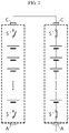
- the diagnosing apparatus 10 is a device for diagnosing a failure of switch units S1 to Sn included in a multi battery pack MP in which first to n th battery packs P1 to Pn are connected in parallel through a parallel link node N.
- the third switch unit S3 includes a third high-potential switch S3 + installed at a high-potential side of the third battery pack P3 and a third low-potential switch S3 - installed at a low-potential side of the third battery pack P3.
- the n th switch unit Sn includes an n th high-potential switch Sn + installed at a high-potential side of the n th battery pack Pn and an n th low-potential switch Sn - installed at a low-potential side of the n th battery pack Pn.
- a capacitor Cap is provided at a front end of the load L.
- the capacitor Cap is connected in parallel between the multi battery pack MP and the load L.
- the capacitor Cap functions as a filter to prevent a noise signal from being applied toward the load L.
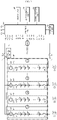
- the diagnosing apparatus 10 includes first to n th current sensors I1 to In installed on power lines connected to the first to n th battery packs P1 to Pn, respectively, to measure a current flowing through each battery pack. That is, the first current sensor I1 measures the magnitude of current flowing through the first battery pack P1. In addition, the second current sensor 12 measures the magnitude of current flowing through the second battery pack P2. In addition, the third current sensor 13 measures the magnitude of current flowing through the third battery pack P3. The n th current sensor In measures the magnitude of current flowing through the n th battery pack Pn. Although not shown in the drawing, the fourth to n-1 th current sensors measure the magnitude of currents flowing through the fourth to n-1 th battery packs, respectively. In the drawing, it is shown that first to n th current sensors I1 to In are included in the battery packs, respectively. However, in the present disclosure, the first to n th current sensors I1 to In may also be installed outside the battery packs, without limitation.
- the present disclosure may be applied to diagnose a failure of the switch unit included in each battery pack and/or degradation of the battery pack while the multi battery pack MP is being discharged or charged.
- the precharge current is a sum current of the pack currents discharged from the first to n th battery packs P1 to Pn, and the magnitude of the pack current of a k th battery pack Pk varies with time according to Equation 1 below.
- I k V pack , k / R in , k Exp ⁇ t / RC
- the control unit 20 measures the n number of pack currents I k (k is 1 to n) flowing from each battery pack to the capacitor Cap by using the first to n th current sensors I1 to In at a time point when a preset time passes after turning on the precharge switch FS, and record the same in the storage unit 30.
- the pack current I k may be measured at a preset diagnosis time point while the multi battery pack MP is being charged or discharged.
- control unit 20 calculates an average value (Avr current ) and standard deviation ( ⁇ current ) of the n number of measured pack currents and records the same in the storage unit 30.
- control unit 20 identifies a battery pack whose pack current I k has a magnitude smaller than the average value by a threshold value or more. In addition, the control unit 20 determines that an open failure occurs at the switch unit included in the identified battery pack, and outputs information (e.g., ID) about the corresponding battery pack.
- information e.g., ID
- the control unit 20 identifies a battery pack whose pack current I k has a magnitude different from the average value (Avr current ) by ⁇ ⁇ ⁇ current or more, namely smaller than the average value (Avr current ) by ⁇ ⁇ ⁇ current or more, and determines that an open failure occurs at the switch unit included in the identified battery pack.
- ⁇ has a value between 1.0 and 2.0, and is preferably 1.5.
- the control unit 20 outputs the information (e.g., ID) about the battery pack including the switch unit in which the open failure occurs. The embodiment related to the output will be described later.
- control unit 20 periodically measure the current flowing through each battery pack and the voltage applied between the positive electrode terminal and the negative electrode terminal by using the first to n th current sensors I1 to In and the first to n th voltage sensors V1 to Vn while the multi battery pack MP is being charged or discharged, and record the same in the storage unit 30.
- control unit 20 determines the n number of internal resistances R in,k (k is 1 to n) for the first to n th battery packs P1 to Pn from the plurality of voltage data and the plurality of current data measured for each battery pack, and records the same in the storage unit 30. In addition, the control unit 20 calculates an average value AvrR and standard deviation ⁇ R of the n number of internal resistances R in , 1 to R in,n and records the same in the storage unit 30.
- the open failure diagnosis logic of the switch unit may be modified as follows.
- control unit 20 identifies a battery pack whose internal resistance R in,k is different from the average value Avr R by less than a threshold value and whose pack current I k has a magnitude different from the average value by a threshold value or more.
- control unit 20 determines that an open failure occurs at the switch unit included in the identified battery pack, and outputs information (e.g., ID) about the corresponding battery pack.
- the control unit 20 identifies a battery pack whose internal resistance R in,k is different from the average value Avr R by less than ⁇ ⁇ ⁇ R , namely whose internal resistance R in,k is not greater than the average value AvrR by ⁇ ⁇ ⁇ R or more, and whose pack current I k has a magnitude different from the average value Avr current by ⁇ ⁇ ⁇ current or more, namely whose pack current I k has a magnitude smaller than the average value Avr current by ⁇ ⁇ ⁇ current or more.
- ⁇ has a value between 1.0 and 2.0, and is preferably 1.5.
- the control unit 20 determines that an open failure occurs at the switch unit included in the identified battery pack, and outputs information (e.g., ID) about the corresponding battery pack.
- the diagnosing apparatus 10 may include a display unit 40.
- the control unit 20 may visually output the information about the battery pack including the switch unit at which an open failure occurs through the display unit 40.
- the control unit 20 may visually output the information about the battery pack whose internal resistance increases by a threshold value or more due to degradation through the display unit 40.
- the display unit 40 is not necessarily included in the diagnosing apparatus 10, and may be included in another device.
- the control unit 20 is not directly connected to the display unit 40, but is indirectly connected to the display unit 40 through a control means included in another device. Therefore, it should be understood that the electrical connection between the display unit 40 and the control unit 20 also includes such an indirect connection.
- the control unit 20 may provide the diagnosis information to another device including a display unit.
- the control unit 20 may be connected to another device to enable data transmission, the another device may receive the information about the battery pack including the switch unit at which an open failure occurs or the information about a degraded battery pack whose internal resistance increases by the threshold value or more, and the another device may display the received information about the battery pack through a display unit connected thereto as a graphic user interface.
- the diagnosing apparatus 10 may include a notification unit 50.
- the control unit 20 may audibly output the information about the battery pack including the switch unit at which an open failure occurs through the notification unit 50.
- the control unit 20 may audibly output the information about the degraded battery pack whose internal resistance increases by the threshold value or more due to degradation through the notification unit 50.
- the information output through the notification unit 50 may be a voice message indicating that a failure occurs at the switch unit and thus the battery pack needs to be inspected.
- the voice message may include a message indicating that a degraded battery pack whose internal resistance increases by the threshold value or more needs to be inspected.
- the notification unit 50 may simply output a preset warning sound.
- the notification unit 50 is a means capable of outputting sound, there is no special limitation on its type.
- the notification unit 50 may be a speaker or a buzzer.
- the diagnosing apparatus 10 may include a communication unit 60.
- the control unit 20 may transmit the information about the battery pack including the switch unit at which an open failure occurs to an external device through the communication unit 60.
- the control unit 20 may transmit the information about a degraded battery pack whose internal resistance increases by the threshold value or more due to degradation to an external device through the communication unit 60.
- the control unit 20 may generate communication data including the information (e.g., ID) about the battery pack including the switch unit at which an open failure occurs or about a degraded battery pack whose internal resistance increases by the threshold value or more due to degradation, and then output the generated communication data through the communication unit 60.
- the communication data may be transferred to a control unit included in an external device through a communication network.
- the control unit of the external device may extract the information (e.g., ID) about the battery pack including the switch unit at which an open failure occurs or about a degraded battery pack whose internal resistance increases by the threshold value or more due to degradation from the communication data, and visually display the extracted information on a display unit connected to the external device.
- the type of the storage unit 30 is a storage medium capable of recording and erasing information.
- the storage unit 30 may be a RAM, a ROM, an EEPROM, a register, or a flash memory.
- the storage unit 30 may also be electrically connected to the control unit 20 through, for example, a data bus so as to be accessed by the control unit 20.
- control unit 20 may control the first to n th voltage sensors V1 to Vn, receive voltage measurement signals V1 to Vn from the first to n th voltage sensors V1 to Vn to determine a voltage of each battery pack, and record the same in the storage unit 30.
- control unit 20 may control the first to n th current sensors I1 to In, receive current measurement signals I1 to In from the first to n th current sensors I1 to In to determine the magnitude of current flowing through each battery pack, and record the same in the storage unit 30.
- control unit 20 may optionally include a processor, an application-specific integrated circuit (ASIC), another chipset, a logic circuit, a register, a communication modem, a data processing device, or the like, known in the art to execute the various control logics described above.
- control logic when the control logic is implemented in software, the control unit 20 may be implemented as a set of program modules.
- the program module may be stored in a memory and executed by a processor.
- the memory may be provided inside or outside the processor and be connected to the processor through various well-known computer components. Also, the memory may be included in the storage unit 30.
- the memory refers to a device in which information is stored, regardless of the type of device, and does not refer to a specific memory device.
- the diagnosing apparatus 10 may be included in a battery management system 100 as shown in FIG. 9 .
- the battery management system 100 controls the overall operation related to charging and discharging of a battery, and is a computing system called a battery management system (BMS) in the art.
- BMS battery management system
- the electric driving mechanism 200 may be a mobile computer device such as a mobile phone, a laptop computer and a tablet computer, or a handheld multimedia device such as a digital camera, a video camera and an audio/video reproduction device.
- a mobile computer device such as a mobile phone, a laptop computer and a tablet computer
- a handheld multimedia device such as a digital camera, a video camera and an audio/video reproduction device.
- FIG. 5 is a flowchart for specifically illustrating a method for periodically calculating an internal resistance of each battery pack included in the multi battery pack MP by the control unit 20 according to an embodiment of the present disclosure.
- Step S10 the control unit 20 monitors the magnitude of a current flowing through a conductive wire using a current sensor (not shown) installed on the conductive wire through which a charging current or a discharging current flows, and if the magnitude of the current is above a certain level, the control unit 20 determines that the multi battery pack MP is being charged or discharged.
- a current sensor not shown
- Step S20 the control unit 20 measures currents flowing through the first to n th battery packs P1 to Pn and voltages of the first to n th battery packs P1 to Pn at regular time intervals by using the first to n th current sensors I1 to In and the first to n th voltage sensors V1 to Vn, and records the same in the storage unit 30.
- Step S30 proceeds after Step S20.
- Step S60 determines whether the internal resistance R in,k of each battery pack or not. If the determination result of Step S60 is YES, the control unit 20 proceeds to Step S20 to repeat the process of calculating the internal resistance R in,k of each battery pack and calculating the average value AvrR and standard deviation ⁇ R of the n number of internal resistances. Meanwhile, if the determination result of Step S60 is NO, the control unit 20 ends the logic for calculating the internal resistance of each battery pack.
- the present disclosure can be applied to diagnose a failure of the switch unit included in each battery pack and/or degradation of the battery pack while the multi battery pack MP is being discharged or charged.
- Step S70 the control unit 20 determines whether there is a discharging request from a control device that manages the load L. To this end, the control unit 20 monitors whether a discharging request message is received from the control device of the load L by means of the communication unit 60.
- Step S80 the control unit 20 turns on the first to n th switch units S1 to Sn respectively included in the first to n th battery packs P1 to Pn.
- Step S90 proceeds after Step S80.
- Step S110 If the determination result of Step S110 is YES, the control unit 20 shifts the process to Step S120.
- Step S170 If the determination result of Step S170 is YES, namely if the magnitude of the pack current flowing from the first battery pack to the capacitor Cap is smaller than the average value by ⁇ ⁇ ⁇ current or more, the control unit 20 shifts the process to Step S180.
- Step S180 the control unit 20 determines whether ⁇ R in,k is greater than or equal to ⁇ ⁇ ⁇ R .
- ⁇ has a value between 1.0 and 2.0, and may be preferably 1.5.
- Step S180 If the determination result of Step S180 is YES, namely if the internal resistance R in,1 of the first battery pack is greater than the average value AvrR of the internal resistances by ⁇ ⁇ ⁇ R or more, the control unit 20 shifts the process to S190.
- the internal resistance R in,1 of the first battery pack is greater than the average value AvrR of the internal resistances by ⁇ ⁇ ⁇ R or more, it means that the degree of degradation of the battery pack is considerably greater than that of the remaining battery packs. In this case, the magnitude of the pack current flowing from the battery pack to the capacitor Cap is considerably smaller than the average value.
- Step S190 the control unit 20 determines that the magnitude of the pack current I 1 of the first battery pack is smaller than the average value Avr current by ⁇ ⁇ ⁇ current or more because the internal resistance of the pack increases greater than the average value by ⁇ ⁇ ⁇ R or more, not due to the failure of the switch unit but due to the degradation of the first battery pack, thereby to decrease the magnitude of the pack current.
- Step S200 proceeds after Step S190.
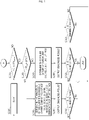
- the average value AvrR and standard deviation ⁇ R of the internal resistances of the first to fifth battery packs are 110.4 milliohms and 7.33 milliohms, respectively.
- ⁇ value is set as 1.5.
- the difference between the internal resistance and the average value is greatest for the fifth battery pack, but is 1.17 times of ⁇ R .
- a minus sign means that the internal resistance is smaller than the average value
- a plus sign means that the internal resistance is greater than the average value.
- the internal resistance of the fifth battery pack is not greater than the average value by 1.5 ⁇ R or more and the measured value of the pack current is greater than the average value by 1.5 ⁇ current or more, it may be determined that an open failure occurs at the switch unit included in the battery pack.
- the open failure refers to a case where an open failure occurs in at least one of the high-potential switch and the low-potential switch of the switch unit.
- a failure of the switch unit included in each battery pack is diagnosed by statistically analyzing the measured value of the pack current flowing through each battery pack without measuring the magnitude of the total current flowing through the multi battery pack.
- each element may be selectively integrated with other elements or each element may be divided into sub-elements for effective implementation control logic(s).
- functional identity can be acknowledged for the integrated or divided elements, the integrated or divided elements fall within the scope of the present disclosure.
Landscapes
- Engineering & Computer Science (AREA)
- Power Engineering (AREA)
- General Physics & Mathematics (AREA)
- Physics & Mathematics (AREA)
- General Chemical & Material Sciences (AREA)
- Chemical Kinetics & Catalysis (AREA)
- Manufacturing & Machinery (AREA)
- Chemical & Material Sciences (AREA)
- Electrochemistry (AREA)
- Microelectronics & Electronic Packaging (AREA)
- Sustainable Energy (AREA)
- Transportation (AREA)
- Mechanical Engineering (AREA)
- Sustainable Development (AREA)
- Life Sciences & Earth Sciences (AREA)
- Health & Medical Sciences (AREA)
- General Health & Medical Sciences (AREA)
- Medical Informatics (AREA)
- Secondary Cells (AREA)
- Charge And Discharge Circuits For Batteries Or The Like (AREA)
- Tests Of Electric Status Of Batteries (AREA)
Applications Claiming Priority (3)
| Application Number | Priority Date | Filing Date | Title |
|---|---|---|---|
| KR20190145238 | 2019-11-13 | ||
| KR1020200151350A KR20210058717A (ko) | 2019-11-13 | 2020-11-12 | 멀티 배터리 팩에 포함된 스위치부의 고장 진단 장치 및 방법 |
| PCT/KR2020/016035 WO2021096312A1 (fr) | 2019-11-13 | 2020-11-13 | Appareil et procédé pour diagnostiquer un dysfonctionnement de l'unité de commutation incluse dans un bloc-batterie multiple |
Publications (2)
| Publication Number | Publication Date |
|---|---|
| EP3985403A1 true EP3985403A1 (fr) | 2022-04-20 |
| EP3985403A4 EP3985403A4 (fr) | 2022-08-10 |
Family
ID=75913124
Family Applications (1)
| Application Number | Title | Priority Date | Filing Date |
|---|---|---|---|
| EP20888006.2A Pending EP3985403A4 (fr) | 2019-11-13 | 2020-11-13 | Appareil et procédé pour diagnostiquer un dysfonctionnement de l'unité de commutation incluse dans un bloc-batterie multiple |
Country Status (5)
| Country | Link |
|---|---|
| US (1) | US11815556B2 (fr) |
| EP (1) | EP3985403A4 (fr) |
| JP (1) | JP7248220B2 (fr) |
| CN (1) | CN113874741B (fr) |
| WO (1) | WO2021096312A1 (fr) |
Family Cites Families (26)
| Publication number | Priority date | Publication date | Assignee | Title |
|---|---|---|---|---|
| JP4728303B2 (ja) | 2007-08-31 | 2011-07-20 | パナソニック株式会社 | 充電回路、及びこれを備えた電池パック、充電システム |
| CN101645609B (zh) * | 2008-08-08 | 2012-07-04 | 凹凸电子(武汉)有限公司 | 电池系统及其充/放电电路和充/放电控制方法 |
| JP5564561B2 (ja) * | 2010-04-23 | 2014-07-30 | 株式会社日立製作所 | 組電池および組電池の制御装置 |
| KR101058682B1 (ko) * | 2010-06-18 | 2011-08-22 | 주식회사 엘지화학 | 배터리 팩의 충방전 전류를 제어하는 배터리 팩 보호 장치와 이를 포함하는 배터리 팩 및 멀티 배터리 팩 시스템 |
| KR20120005729A (ko) | 2010-07-09 | 2012-01-17 | (주)브이이엔에스 | 전기자동차 및 그 동작방법 |
| CN103097177B (zh) | 2010-07-09 | 2015-09-02 | Lg电子株式会社 | 电动汽车及其控制方法 |
| CN102577015A (zh) | 2010-10-15 | 2012-07-11 | 三洋电机株式会社 | 蓄电系统用的自诊断装置 |
| JP5733786B2 (ja) | 2010-11-02 | 2015-06-10 | Necエナジーデバイス株式会社 | 二次電池システム |
| JP2013038884A (ja) | 2011-08-05 | 2013-02-21 | Sharp Corp | 充放電制御装置 |
| US9341678B2 (en) * | 2011-09-28 | 2016-05-17 | Alliance For Sustainable Energy, Llc | Fail-safe designs for large capacity battery systems |
| JP5910172B2 (ja) * | 2012-03-01 | 2016-04-27 | 株式会社Gsユアサ | スイッチ故障診断装置、電池パックおよびスイッチ故障診断プログラム、スイッチ故障診断方法 |
| PL2720056T3 (pl) * | 2012-04-04 | 2021-07-12 | Lg Chem, Ltd. | Urządzenie do mierzenia rezystancji izolacji, mające funkcję samodiagnozowania usterek, oraz wykorzystujący je sposób samodiagnozowania |
| KR101648239B1 (ko) * | 2012-06-29 | 2016-08-12 | 삼성에스디아이 주식회사 | 돌입 전류를 저감하는 에너지 저장 장치 및 그 방법 |
| JP5983171B2 (ja) | 2012-08-10 | 2016-08-31 | 株式会社Gsユアサ | スイッチ故障診断装置、蓄電装置 |
| KR101551035B1 (ko) | 2013-12-30 | 2015-09-08 | 현대자동차주식회사 | 프리 차지 중 고장 진단 방법 |
| KR101551088B1 (ko) | 2014-05-09 | 2015-09-07 | 현대자동차주식회사 | 배터리 승온 시스템 및 릴레이 고장 검출 장치 및 그 방법 |
| JP2016082667A (ja) | 2014-10-15 | 2016-05-16 | 株式会社豊田自動織機 | 電源装置及び異常検出方法 |
| JP6414460B2 (ja) | 2014-12-18 | 2018-10-31 | 株式会社デンソー | バッテリの劣化状態判定装置及び劣化状態判定方法 |
| CN104578307B (zh) | 2015-01-23 | 2017-01-18 | 浙江大学 | 一种容错锂离子电池组的结构及故障检测方法 |
| KR102059076B1 (ko) * | 2016-02-19 | 2020-02-11 | 주식회사 엘지화학 | 스위치 부품의 고장 진단 장치 및 방법 |
| KR101689501B1 (ko) | 2016-03-03 | 2016-12-23 | 두산중공업 주식회사 | 싸이리스터 스위치 고장 검지 장치를 구비한 다중 위상제어 정류기 및 고장 검지 방법 |
| KR102058198B1 (ko) | 2016-12-12 | 2019-12-20 | 주식회사 엘지화학 | 상시 전원 공급을 위한 병렬 회로를 이용하여 배터리의 릴레이의 고장을 진단하는 장치 및 방법 |
| JP6798423B2 (ja) | 2017-05-29 | 2020-12-09 | 株式会社豊田自動織機 | 電池パック |
| KR102204983B1 (ko) | 2017-09-25 | 2021-01-18 | 주식회사 엘지화학 | 배터리 관리 장치와 이를 포함하는 배터리 팩 및 자동차 |
| KR102348105B1 (ko) * | 2018-01-15 | 2022-01-05 | 주식회사 엘지에너지솔루션 | 버스바의 고장을 진단하기 위한 배터리 관리 시스템 및 방법 |
| US11233407B2 (en) * | 2019-03-01 | 2022-01-25 | GM Global Technology Operations LLC | Switch control systems and methods for battery with adjustable capacity |
-
2020
- 2020-11-13 WO PCT/KR2020/016035 patent/WO2021096312A1/fr unknown
- 2020-11-13 JP JP2021551545A patent/JP7248220B2/ja active Active
- 2020-11-13 US US17/600,173 patent/US11815556B2/en active Active
- 2020-11-13 CN CN202080033065.XA patent/CN113874741B/zh active Active
- 2020-11-13 EP EP20888006.2A patent/EP3985403A4/fr active Pending
Also Published As
| Publication number | Publication date |
|---|---|
| WO2021096312A1 (fr) | 2021-05-20 |
| JP2022522753A (ja) | 2022-04-20 |
| US11815556B2 (en) | 2023-11-14 |
| JP7248220B2 (ja) | 2023-03-29 |
| EP3985403A4 (fr) | 2022-08-10 |
| CN113874741B (zh) | 2024-03-15 |
| CN113874741A (zh) | 2021-12-31 |
| US20220155371A1 (en) | 2022-05-19 |
Similar Documents
| Publication | Publication Date | Title |
|---|---|---|
| US10782350B2 (en) | Apparatus and method for diagnosing failure of switch element | |
| KR101470553B1 (ko) | 배터리의 절연 저항 측정 장치 및 방법 | |
| EP3754347B1 (fr) | Dispositif et procédé de diagnostic de commutateur | |
| KR100958795B1 (ko) | 배터리 누설전류 감지 장치 및 방법, 및 상기 장치를 포함하는 배터리 구동 장치 및 배터리 팩 | |
| US20220179008A1 (en) | Battery Diagnosing Apparatus and Method | |
| CN111433618B (zh) | 电流测量设备和方法及包括电流测量设备的电池组 | |
| US12081048B2 (en) | Apparatus and method for balancing battery packs connected in parallel | |
| KR20130112802A (ko) | 고장 자가 진단 기능을 구비한 절연 저항 측정 장치 및 이를 이용한 자가 진단 방법 | |
| US20220404418A1 (en) | Relay Diagnosis Apparatus, Relay Diagnosis Method, Battery System and Electric Vehicle | |
| EP3624250B1 (fr) | Bloc batterie | |
| EP3832326B1 (fr) | Appareil de diagnostic de bloc-batterie | |
| EP3972074A1 (fr) | Appareil et procédé pour commander l'opération de mise en marche d'unités de commutation comprises dans un bloc-batterie multiple parallèle | |
| EP4145667A1 (fr) | Dispositif et procédé de commande de sortie de module multi-bloc parallèle | |
| KR20190075609A (ko) | 전류 센서 진단 장치 및 방법 | |
| EP4099034A1 (fr) | Dispositif de diagnostic de relais, procédé de diagnostic de relais, système de batterie et véhicule électrique | |
| EP3754350A1 (fr) | Dispositif et procédé de diagnostic de commutateur | |
| KR20210058717A (ko) | 멀티 배터리 팩에 포함된 스위치부의 고장 진단 장치 및 방법 | |
| EP3985403A1 (fr) | Appareil et procédé pour diagnostiquer un dysfonctionnement de l'unité de commutation incluse dans un bloc-batterie multiple | |
| EP3974247A1 (fr) | Dispositif et procédé de commande de sortie de système à blocs multiples parallèle | |
| KR20210053067A (ko) | 병렬 연결된 멀티 배터리 팩의 케이블 열화 진단 장치 및 방법 | |
| KR20230052763A (ko) | 배터리 진단 장치, 배터리 팩, 전기 차량, 및 배터리 진단 방법 | |
| KR20200038818A (ko) | 전류 센서 진단 장치 및 방법 | |
| KR20240126342A (ko) | 스위치 고장 진단 기능을 가진 배터리 관리 장치, 이를 포함하는 시스템 및 방법 | |
| KR20240038887A (ko) | 배터리 진단 장치, 배터리 진단 방법, 배터리 팩 및 자동차 | |
| KR20240038886A (ko) | 배터리 진단 장치, 배터리 진단 방법, 배터리 팩 및 자동차 |
Legal Events
| Date | Code | Title | Description |
|---|---|---|---|
| STAA | Information on the status of an ep patent application or granted ep patent |
Free format text: STATUS: THE INTERNATIONAL PUBLICATION HAS BEEN MADE |
|
| PUAI | Public reference made under article 153(3) epc to a published international application that has entered the european phase |
Free format text: ORIGINAL CODE: 0009012 |
|
| STAA | Information on the status of an ep patent application or granted ep patent |
Free format text: STATUS: REQUEST FOR EXAMINATION WAS MADE |
|
| 17P | Request for examination filed |
Effective date: 20220114 |
|
| AK | Designated contracting states |
Kind code of ref document: A1 Designated state(s): AL AT BE BG CH CY CZ DE DK EE ES FI FR GB GR HR HU IE IS IT LI LT LU LV MC MK MT NL NO PL PT RO RS SE SI SK SM TR |
|
| A4 | Supplementary search report drawn up and despatched |
Effective date: 20220712 |
|
| RIC1 | Information provided on ipc code assigned before grant |
Ipc: H02J 7/00 20060101ALI20220706BHEP Ipc: G01R 19/165 20060101ALI20220706BHEP Ipc: B60L 3/00 20190101ALI20220706BHEP Ipc: H01M 10/48 20060101ALI20220706BHEP Ipc: G01R 31/389 20190101ALI20220706BHEP Ipc: G01R 31/36 20200101ALI20220706BHEP Ipc: G01R 31/385 20190101ALI20220706BHEP Ipc: G01R 31/50 20200101ALI20220706BHEP Ipc: G01R 31/327 20060101AFI20220706BHEP |
|
| DAV | Request for validation of the european patent (deleted) | ||
| DAX | Request for extension of the european patent (deleted) |