EP3985399A1 - Automatic analysis device - Google Patents
Automatic analysis device Download PDFInfo
- Publication number
- EP3985399A1 EP3985399A1 EP20825127.2A EP20825127A EP3985399A1 EP 3985399 A1 EP3985399 A1 EP 3985399A1 EP 20825127 A EP20825127 A EP 20825127A EP 3985399 A1 EP3985399 A1 EP 3985399A1
- Authority
- EP
- European Patent Office
- Prior art keywords
- reagent
- pipe
- blowing
- wall
- reagent cooler
- Prior art date
- Legal status (The legal status is an assumption and is not a legal conclusion. Google has not performed a legal analysis and makes no representation as to the accuracy of the status listed.)
- Granted
Links
Images


Classifications
-
- G—PHYSICS
- G01—MEASURING; TESTING
- G01N—INVESTIGATING OR ANALYSING MATERIALS BY DETERMINING THEIR CHEMICAL OR PHYSICAL PROPERTIES
- G01N35/00—Automatic analysis not limited to methods or materials provided for in any single one of groups G01N1/00 - G01N33/00; Handling materials therefor
- G01N35/10—Devices for transferring samples or any liquids to, in, or from, the analysis apparatus, e.g. suction devices, injection devices
- G01N35/1002—Reagent dispensers
-
- B—PERFORMING OPERATIONS; TRANSPORTING
- B01—PHYSICAL OR CHEMICAL PROCESSES OR APPARATUS IN GENERAL
- B01L—CHEMICAL OR PHYSICAL LABORATORY APPARATUS FOR GENERAL USE
- B01L3/00—Containers or dishes for laboratory use, e.g. laboratory glassware; Droppers
- B01L3/50—Containers for the purpose of retaining a material to be analysed, e.g. test tubes
- B01L3/502—Containers for the purpose of retaining a material to be analysed, e.g. test tubes with fluid transport, e.g. in multi-compartment structures
-
- B—PERFORMING OPERATIONS; TRANSPORTING
- B01—PHYSICAL OR CHEMICAL PROCESSES OR APPARATUS IN GENERAL
- B01L—CHEMICAL OR PHYSICAL LABORATORY APPARATUS FOR GENERAL USE
- B01L2200/00—Solutions for specific problems relating to chemical or physical laboratory apparatus
- B01L2200/02—Adapting objects or devices to another
- B01L2200/026—Fluid interfacing between devices or objects, e.g. connectors, inlet details
-
- B—PERFORMING OPERATIONS; TRANSPORTING
- B01—PHYSICAL OR CHEMICAL PROCESSES OR APPARATUS IN GENERAL
- B01L—CHEMICAL OR PHYSICAL LABORATORY APPARATUS FOR GENERAL USE
- B01L2200/00—Solutions for specific problems relating to chemical or physical laboratory apparatus
- B01L2200/16—Reagents, handling or storing thereof
-
- B—PERFORMING OPERATIONS; TRANSPORTING
- B01—PHYSICAL OR CHEMICAL PROCESSES OR APPARATUS IN GENERAL
- B01L—CHEMICAL OR PHYSICAL LABORATORY APPARATUS FOR GENERAL USE
- B01L2300/00—Additional constructional details
- B01L2300/04—Closures and closing means
- B01L2300/046—Function or devices integrated in the closure
- B01L2300/048—Function or devices integrated in the closure enabling gas exchange, e.g. vents
-
- B—PERFORMING OPERATIONS; TRANSPORTING
- B01—PHYSICAL OR CHEMICAL PROCESSES OR APPARATUS IN GENERAL
- B01L—CHEMICAL OR PHYSICAL LABORATORY APPARATUS FOR GENERAL USE
- B01L2300/00—Additional constructional details
- B01L2300/06—Auxiliary integrated devices, integrated components
- B01L2300/0681—Filter
-
- B—PERFORMING OPERATIONS; TRANSPORTING
- B01—PHYSICAL OR CHEMICAL PROCESSES OR APPARATUS IN GENERAL
- B01L—CHEMICAL OR PHYSICAL LABORATORY APPARATUS FOR GENERAL USE
- B01L2300/00—Additional constructional details
- B01L2300/14—Means for pressure control
-
- B—PERFORMING OPERATIONS; TRANSPORTING
- B01—PHYSICAL OR CHEMICAL PROCESSES OR APPARATUS IN GENERAL
- B01L—CHEMICAL OR PHYSICAL LABORATORY APPARATUS FOR GENERAL USE
- B01L2300/00—Additional constructional details
- B01L2300/18—Means for temperature control
- B01L2300/1894—Cooling means; Cryo cooling
-
- G—PHYSICS
- G01—MEASURING; TESTING
- G01N—INVESTIGATING OR ANALYSING MATERIALS BY DETERMINING THEIR CHEMICAL OR PHYSICAL PROPERTIES
- G01N35/00—Automatic analysis not limited to methods or materials provided for in any single one of groups G01N1/00 - G01N33/00; Handling materials therefor
- G01N2035/00346—Heating or cooling arrangements
- G01N2035/00435—Refrigerated reagent storage
-
- G—PHYSICS
- G01—MEASURING; TESTING
- G01N—INVESTIGATING OR ANALYSING MATERIALS BY DETERMINING THEIR CHEMICAL OR PHYSICAL PROPERTIES
- G01N35/00—Automatic analysis not limited to methods or materials provided for in any single one of groups G01N1/00 - G01N33/00; Handling materials therefor
- G01N2035/00346—Heating or cooling arrangements
- G01N2035/00445—Other cooling arrangements
-
- G—PHYSICS
- G01—MEASURING; TESTING
- G01N—INVESTIGATING OR ANALYSING MATERIALS BY DETERMINING THEIR CHEMICAL OR PHYSICAL PROPERTIES
- G01N35/00—Automatic analysis not limited to methods or materials provided for in any single one of groups G01N1/00 - G01N33/00; Handling materials therefor
- G01N2035/00346—Heating or cooling arrangements
- G01N2035/00455—Controlling humidity in analyser
-
- G—PHYSICS
- G01—MEASURING; TESTING
- G01N—INVESTIGATING OR ANALYSING MATERIALS BY DETERMINING THEIR CHEMICAL OR PHYSICAL PROPERTIES
- G01N35/00—Automatic analysis not limited to methods or materials provided for in any single one of groups G01N1/00 - G01N33/00; Handling materials therefor
- G01N35/02—Automatic analysis not limited to methods or materials provided for in any single one of groups G01N1/00 - G01N33/00; Handling materials therefor using a plurality of sample containers moved by a conveyor system past one or more treatment or analysis stations
- G01N35/04—Details of the conveyor system
- G01N2035/0439—Rotary sample carriers, i.e. carousels
- G01N2035/0443—Rotary sample carriers, i.e. carousels for reagents
Definitions
- the present invention relates to an automatic analyzer.
- an automatic analyzer that performs analysis by mixing various reagents and a sample is provided with a reagent cooler that holds the various reagents.
- the reagent cooler has a reagent aspiration hole in a portion of the lid member so that the held reagent can be easily aspirated, and the reagent aspiration hole is always open.
- Patent Literature 1 discloses a technique that prevents inflow of outside air and dew condensation by feeding cooled air from outside the reagent cooler.
- Patent Literature 1 Japanese Patent Application Laid-Open No. 2009-270857 .
- cooling of the reagent cooler In the prior art, cooling of the reagent cooler, cooling of the air to be fed into the reagent cooler, and air stirring means to uniformize the temperature inside the reagent cooler have been performed using different devices. Using different devices in this way poses a problem about a rise in the power consumption of the automatic analyzer and a problem that the structure becomes complicated.
- the object of the present invention is to provide an automatic analyzer that solves the above problems and can prevent dew condensation in the reagent cooler and permit temperature uniformization with low power consumption and a simple structure.
- the present invention provides an automatic analyzer that performs analysis by mixing a reagent and a sample and includes: a reagent cooler that stores a reagent vessel; a refrigerant pipe that is disposed inside the outer wall of the reagent cooler and circulates a refrigerant inside the outer wall; a blowing pipe that is disposed inside the outer wall and guides outside air existing outside the reagent cooler to the inside of the reagent cooler; and a blowing unit that is disposed at the blowing pipe and diffuses the outside air into the inside of the reagent cooler through the blowing pipe.
- a reagent cooler with low power consumption and a simple structure, in which outside air is taken into the reagent cooler and cooled with the cooled air of the refrigerant cooler itself during that process and by blowing air into the reagent cooler, the inside of the reagent cooler is positively pressurized to prevent inflow of outside air through an aspiration hole and thereby prevent dew condensation and the temperature in the cooler can be made uniform by blowing the outside air.
- the first embodiment is an embodiment as an automatic analyzer that performs analysis by mixing a reagent and a sample and includes: a reagent cooler that stores a reagent vessel; a refrigerant pipe that is disposed inside an outer wall of the reagent cooler and circulates a refrigerant inside the outer wall; a blowing pipe that is disposed inside the outer wall and guides outside air existing outside the reagent cooler to the inside of the reagent cooler; and a blowing unit that is disposed at the blowing pipe and diffuses the outside air into the inside of the reagent cooler through the blowing pipe.
- FIG. 1 is a plan view that shows an outline of an automatic analyzer 101.
- the automatic analyzer 101 mixes a sample and a reagent and automatically analyzes the mixed sample to be measured.
- the automatic analyzer 101 includes a transport line 1, a sample probe 2 for aspirating a sample, a reaction vessel supplier 3, a reaction vessel supply mechanism 4, a reaction vessel table 5 (incubator), a reaction measurement device 6, a reagent stirring rod 7, a reagent disk 8, a reagent probe 102, a reagent cooler 103, and further an intake port 112, a filter 113, and a blowing unit 114.
- the reaction vessel supplier 3 holds a plurality of reaction vessels 9.
- the reaction vessel supply mechanism 4 supplies a reaction vessel 9 held by the reaction vessel supplier 3 to the reaction vessel table 5.
- the reaction vessel table 5 moves the supplied reaction vessel 9 to the sample discharge position where a sample is discharged from the sample probe 2, by its own rotation.
- the reagent cooler 103 stores a reagent vessel 107 that contains a reagent.
- the reagent cooler 103 has a cylindrical shape in which the side wall has an outer wall and an inner wall and its top forms a lid.
- FIG. 1 shows the inside of the reagent cooler 103 in which the lid is partially deleted. As illustrated in the figure, an aspiration hole 104 is made in the lid at the top of the reagent cooler 103.
- the reagent cooler 103 has an inner wall inside the outer wall.
- the top of the reagent vessel 107 is open.
- the reagent stirring rod 7 is moved to the reagent stirring position where the reagent contained in a reagent vessel 107 is stirred.
- the reagent stirring rod 7 is inserted into the reagent vessel 107 through the aspiration hole 104 and the top of the reagent vessel 107. Then, the reagent stirring rod 7 stirs the reagent contained in the reagent vessel by being rotated while inserted.
- the reagent stirring rod 7 that has stirred the reagent is pulled out of the reagent vessel 107.
- the reagent probe 102 is moved to the reagent aspiration position where the reagent is aspirated from the reagent vessel 107. Then, the reagent probe 102 is inserted into the reagent vessel 107 through the aspiration hole 104 and the top of the reagent vessel 107. Then, the reagent probe 102 aspirates the reagent from the reagent vessel 107 while inserted.
- the reagent probe 102 that has aspirated the reagent is pulled out of the reagent vessel 107. After that, the reagent probe 102 is moved to the reagent discharge position and it discharges the reagent into a reaction vessel 9. After the reagent is discharged, the reaction vessel table 5 moves the reaction vessel 9 to the sample discharge position where the sample is discharged from the sample probe 2, by its own rotation.
- the transport line 1 transports the sample vessel 11 held by a test tube rack 10 to the sample aspiration position where the sample is aspirated from the sample probe 2.
- the sample vessel 11 contains a sample.
- the top of the sample vessel is open. After the sample vessel 11 is transported to the sample aspiration position, the sample probe 2 is inserted from the top of the sample vessel 11. Then, the sample probe 2 aspirates the sample from the sample vessel 11 while inserted.
- the sample probe 2 After aspiration of the sample, the sample probe 2 is pulled out of the sample vessel 11. After that, the sample probe 2 is moved to the sample discharge position. After the sample probe 2 is moved to the sample discharge position, it discharges the aspirated sample into the reaction vessel 9.
- a stirring mechanism (not shown) stirs the reagent and sample that have been discharged into the reaction vessel 9.
- the reagent and sample that have been stirred are left as they are, for a prescribed time.
- the reaction vessel 9 is moved to a reaction measurement device 6.
- the reaction measurement device 6 measures the state of reaction between the reagent and sample contained in the reaction vessel 9 that has been moved.
- At least one reagent vessel 107 for example, four reagent vessels are disposed on the reagent disk 8 and as the reagent disk 8 rotates, the reagent to be stirred and aspirated by the reagent stirring rod 7 and reagent probe 102 can be replaced.
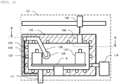
- FIG. 2 is a sectional view taken along line A-A of the automatic analyzer.
- refrigerant pipes 105 are provided in contact with the inner wall of the reagent cooler 103.
- the refrigerant pipe 105 is made of a material with high thermal conductivity.
- the refrigerant pipe 105 is connected to a cooling device 110 and the refrigerant cooled by the cooling device 110 is circulated in the refrigerant pipe 105.
- the refrigerant pipe 105 is cooled by circulation of the refrigerant and the inner wall of the reagent cooler 103 that is in contact with the refrigerant pipe 105 is cooled.
- the cool air from the inner wall is transmitted to the inside of the reagent cooler 103 so that the inside of the reagent cooler 103 is cooled to a given temperature.
- the cooling temperature here is assumed to be approximately 6.5°C.
- a material with low thermal conductivity is filled between the outer wall and inner wall of the reagent cooler 103 (shaded portion in FIG. 2 ) so as to prevent the influence of the outside air temperature.
- a large drain pipe 111 is provided at the bottom of the reagent cooler 103 and if dew condensation occurs inside the reagent cooler 103, dew drops are discharged through the large drain pipe 111 outside the reagent cooler 103 downward in the figure.
- FIG. 3 is a sectional view taken along line B-B of the configuration outline in FIG. 2 .
- a blowing pipe 109 is a pipe to take the air outside the reagent cooler 103 into the reagent cooler 103 through an intake port 112.
- the blowing pipe 109 extends between the inner wall and outer wall of the reagent cooler 103 (shaded portions in FIG. 3 ) and contacts the refrigerant pipes 105 as shown in FIG. 2 .
- the blowing pipe 109 is made of a material with high thermal conductivity and cooled by contact with the refrigerant pipes 105. As it is cooled in this way, the gas passing inside the blowing pipe 109 is also cooled.
- the intake port 112 and blowing port 108 are respectively attached to the start end and terminal end of the blowing pipe 109.
- the intake port 112 is disposed outside the outer wall of the reagent cooler 103 and the blowing port 108 is disposed more inward than the inner wall of the reagent cooler 103 and along the inner wall.
- the blowing pipe 109 includes a blowing unit 114 and a filter 113 that prevents penetration of foreign matters on the intake side of the blowing unit 114.
- One example of the blowing unit 114 may be a fan.
- the blowing unit 114 is located between the intake port 112 and the blowing port 108. As a concrete example of the first embodiment, FIG. 3 shows that the unit is adjacent to the intake port 112, but instead it may be adjacent to the blowing port 108. 115 indicates the flow of air into the intake port 112.
- the length of the blowing pipe 109 is such a length that the temperature of the outside air taken through the intake port 112 at the time when the outside air flows from the blowing port 108 is within 5°C from the temperature in the reagent cooler 103.
- the length should be such that the temperature of the outside air is in the range of 11.5°C to 1.5°C.
- the length of the portion of the blowing pipe 109 existing inside the outer wall of the side wall is set such that the difference between the temperature of the outside air at the time when the outside air is taken into the blowing unit 114 and the temperature in the reagent cooler 103 is 5 degrees or lower.
- blowing pipe 109 that exists inside the outer wall of the reagent cooler 103 should be disposed 45° or larger along the side wall of the cylindrical reagent cooler 103.
- a small drain pipe 106 is provided in the blowing pipe 109 between the intake port 112 and the blowing port 108.
- the small drain pipe 106 is closer to the blowing port 108 than the half point of the blowing pipe 109.
- the start end and terminal end of the blowing pipe are respectively attached to the intake port and blowing port and the small drain pipe with a small diameter is provided closer to the blowing port than the half point of the blowing pipe.
- the terminal end of the small drain pipe 106 is connected to the large drain pipe 111. Consequently, the dew condensation water that is generated in the blowing pipe 109 when the outside air taken in from the intake port 112 by the blowing pipe 109 is cooled in the blowing pipe 109 passes from the small drain pipe 106 through the large drain pipe 111 and is discharged outside the reagent cooler 103 as shown in FIG. 2 .
- the blowing pipe 109 is connected to a pipe whose terminal end is outside the reagent cooler 103.
- This pipe is comprised of a small drain pipe as a small diameter pipe connected to the blowing pipe 109, and a large drain pipe that is provided at the bottom of the reagent cooler and connected to the small diameter pipe and has a larger diameter than the small diameter.
- the large drain pipe as the large diameter pipe has its terminal end outside the reagent cooler.
- the reagent cooler 103 is positively pressurized to prevent inflow of outside air from the aspiration hole 104 in the lid and thereby prevent dew condensation. Furthermore, as the cooled outside air is blown from the blowing port 108 into the reagent cooler 103, the air inside the reagent cooler 103 is stirred and the internal temperature is made uniform.
- the blowing port 108 of the blowing pipe 109 is disposed more inward than the inner wall of the reagent cooler 103 and along the inner wall.
- the present invention is not limited to the abovementioned embodiment but includes various variations.
- the abovementioned embodiment has been described in detail for better understanding of the present invention and the invention is not limited to an embodiment that includes all the elements described above.
Landscapes
- Chemical & Material Sciences (AREA)
- Health & Medical Sciences (AREA)
- General Health & Medical Sciences (AREA)
- Analytical Chemistry (AREA)
- Life Sciences & Earth Sciences (AREA)
- Biochemistry (AREA)
- Physics & Mathematics (AREA)
- General Physics & Mathematics (AREA)
- Immunology (AREA)
- Pathology (AREA)
- Hematology (AREA)
- Clinical Laboratory Science (AREA)
- Chemical Kinetics & Catalysis (AREA)
- Automatic Analysis And Handling Materials Therefor (AREA)
Abstract
Description
- The present invention relates to an automatic analyzer.
- Conventionally, an automatic analyzer that performs analysis by mixing various reagents and a sample is provided with a reagent cooler that holds the various reagents. The reagent cooler has a reagent aspiration hole in a portion of the lid member so that the held reagent can be easily aspirated, and the reagent aspiration hole is always open.
- Generally, the inside of the reagent cooler is kept at a lower temperature than the room temperature. However, since the reagent aspiration hole is always open, outside air flows in through the hole, causing dew condensation inside the reagent cooler. In addition, the inflow of outside air causes a rise in the temperature in the vicinity of the reagent aspiration hole and makes the temperature distribution inside the cooler ununiform. Therefore, Patent Literature 1 discloses a technique that prevents inflow of outside air and dew condensation by feeding cooled air from outside the reagent cooler.
- Patent Literature 1:
Japanese Patent Application Laid-Open No. 2009-270857 - In the prior art, cooling of the reagent cooler, cooling of the air to be fed into the reagent cooler, and air stirring means to uniformize the temperature inside the reagent cooler have been performed using different devices. Using different devices in this way poses a problem about a rise in the power consumption of the automatic analyzer and a problem that the structure becomes complicated.
- The object of the present invention is to provide an automatic analyzer that solves the above problems and can prevent dew condensation in the reagent cooler and permit temperature uniformization with low power consumption and a simple structure.
- In order to achieve the above object, the present invention provides an automatic analyzer that performs analysis by mixing a reagent and a sample and includes: a reagent cooler that stores a reagent vessel; a refrigerant pipe that is disposed inside the outer wall of the reagent cooler and circulates a refrigerant inside the outer wall; a blowing pipe that is disposed inside the outer wall and guides outside air existing outside the reagent cooler to the inside of the reagent cooler; and a blowing unit that is disposed at the blowing pipe and diffuses the outside air into the inside of the reagent cooler through the blowing pipe.
- According to the present invention, it is possible to provide a reagent cooler with low power consumption and a simple structure, in which outside air is taken into the reagent cooler and cooled with the cooled air of the refrigerant cooler itself during that process and by blowing air into the reagent cooler, the inside of the reagent cooler is positively pressurized to prevent inflow of outside air through an aspiration hole and thereby prevent dew condensation and the temperature in the cooler can be made uniform by blowing the outside air.
-
-
FIG. 1 is a plan view showing an outline of an automatic analyzer. -
FIG. 2 is a schematic sectional view taken along line A-A of the automatic analyzer. -
FIG. 3 is a sectional view taken along line B-B of a configuration outline. - Hereinafter, an embodiment of the present invention will be described in detail referring to drawings. In all the drawings that explain the embodiment, basically the same elements are designated by the same reference signs and repeated description thereof is omitted.
- The first embodiment is an embodiment as an automatic analyzer that performs analysis by mixing a reagent and a sample and includes: a reagent cooler that stores a reagent vessel; a refrigerant pipe that is disposed inside an outer wall of the reagent cooler and circulates a refrigerant inside the outer wall; a blowing pipe that is disposed inside the outer wall and guides outside air existing outside the reagent cooler to the inside of the reagent cooler; and a blowing unit that is disposed at the blowing pipe and diffuses the outside air into the inside of the reagent cooler through the blowing pipe.
-
FIG. 1 is a plan view that shows an outline of anautomatic analyzer 101. Theautomatic analyzer 101 mixes a sample and a reagent and automatically analyzes the mixed sample to be measured. As shown inFIG. 1 , theautomatic analyzer 101 includes a transport line 1, asample probe 2 for aspirating a sample, areaction vessel supplier 3, a reactionvessel supply mechanism 4, a reaction vessel table 5 (incubator), areaction measurement device 6, areagent stirring rod 7, areagent disk 8, areagent probe 102, areagent cooler 103, and further anintake port 112, afilter 113, and ablowing unit 114. - The
reaction vessel supplier 3 holds a plurality ofreaction vessels 9. The reactionvessel supply mechanism 4 supplies areaction vessel 9 held by thereaction vessel supplier 3 to the reaction vessel table 5. The reaction vessel table 5 moves the suppliedreaction vessel 9 to the sample discharge position where a sample is discharged from thesample probe 2, by its own rotation. - The
reagent cooler 103 stores areagent vessel 107 that contains a reagent. Thereagent cooler 103 has a cylindrical shape in which the side wall has an outer wall and an inner wall and its top forms a lid.FIG. 1 shows the inside of thereagent cooler 103 in which the lid is partially deleted. As illustrated in the figure, anaspiration hole 104 is made in the lid at the top of thereagent cooler 103. As shown here, thereagent cooler 103 has an inner wall inside the outer wall. - The top of the
reagent vessel 107 is open. Thereagent stirring rod 7 is moved to the reagent stirring position where the reagent contained in areagent vessel 107 is stirred. Thereagent stirring rod 7 is inserted into thereagent vessel 107 through theaspiration hole 104 and the top of thereagent vessel 107. Then, thereagent stirring rod 7 stirs the reagent contained in the reagent vessel by being rotated while inserted. Thereagent stirring rod 7 that has stirred the reagent is pulled out of thereagent vessel 107. - After that, the
reagent probe 102 is moved to the reagent aspiration position where the reagent is aspirated from thereagent vessel 107. Then, thereagent probe 102 is inserted into thereagent vessel 107 through theaspiration hole 104 and the top of thereagent vessel 107. Then, thereagent probe 102 aspirates the reagent from thereagent vessel 107 while inserted. - The
reagent probe 102 that has aspirated the reagent is pulled out of thereagent vessel 107. After that, thereagent probe 102 is moved to the reagent discharge position and it discharges the reagent into areaction vessel 9. After the reagent is discharged, the reaction vessel table 5 moves thereaction vessel 9 to the sample discharge position where the sample is discharged from thesample probe 2, by its own rotation. - The transport line 1 transports the
sample vessel 11 held by atest tube rack 10 to the sample aspiration position where the sample is aspirated from thesample probe 2. Thesample vessel 11 contains a sample. The top of the sample vessel is open. After thesample vessel 11 is transported to the sample aspiration position, thesample probe 2 is inserted from the top of thesample vessel 11. Then, thesample probe 2 aspirates the sample from thesample vessel 11 while inserted. - After aspiration of the sample, the
sample probe 2 is pulled out of thesample vessel 11. After that, thesample probe 2 is moved to the sample discharge position. After thesample probe 2 is moved to the sample discharge position, it discharges the aspirated sample into thereaction vessel 9. - A stirring mechanism (not shown) stirs the reagent and sample that have been discharged into the
reaction vessel 9. The reagent and sample that have been stirred are left as they are, for a prescribed time. After that, thereaction vessel 9 is moved to areaction measurement device 6. Then, thereaction measurement device 6 measures the state of reaction between the reagent and sample contained in thereaction vessel 9 that has been moved. - At least one
reagent vessel 107, for example, four reagent vessels are disposed on thereagent disk 8 and as thereagent disk 8 rotates, the reagent to be stirred and aspirated by thereagent stirring rod 7 andreagent probe 102 can be replaced. -
FIG. 2 is a sectional view taken along line A-A of the automatic analyzer. As shown in the figure, between the inner wall and outer wall of the side wall, lid and bottom of thereagent cooler 103,refrigerant pipes 105 are provided in contact with the inner wall of thereagent cooler 103. Therefrigerant pipe 105 is made of a material with high thermal conductivity. Therefrigerant pipe 105 is connected to acooling device 110 and the refrigerant cooled by thecooling device 110 is circulated in therefrigerant pipe 105. Therefrigerant pipe 105 is cooled by circulation of the refrigerant and the inner wall of thereagent cooler 103 that is in contact with therefrigerant pipe 105 is cooled. The cool air from the inner wall is transmitted to the inside of thereagent cooler 103 so that the inside of thereagent cooler 103 is cooled to a given temperature. - As an example, the cooling temperature here is assumed to be approximately 6.5°C. Furthermore, a material with low thermal conductivity is filled between the outer wall and inner wall of the reagent cooler 103 (shaded portion in
FIG. 2 ) so as to prevent the influence of the outside air temperature. - As shown in
FIG. 2 , alarge drain pipe 111 is provided at the bottom of thereagent cooler 103 and if dew condensation occurs inside thereagent cooler 103, dew drops are discharged through thelarge drain pipe 111 outside thereagent cooler 103 downward in the figure. -
FIG. 3 is a sectional view taken along line B-B of the configuration outline inFIG. 2 . A blowingpipe 109 is a pipe to take the air outside thereagent cooler 103 into thereagent cooler 103 through anintake port 112. The blowingpipe 109 extends between the inner wall and outer wall of the reagent cooler 103 (shaded portions inFIG. 3 ) and contacts therefrigerant pipes 105 as shown inFIG. 2 . The blowingpipe 109 is made of a material with high thermal conductivity and cooled by contact with therefrigerant pipes 105. As it is cooled in this way, the gas passing inside the blowingpipe 109 is also cooled. - The
intake port 112 and blowingport 108 are respectively attached to the start end and terminal end of the blowingpipe 109. Theintake port 112 is disposed outside the outer wall of thereagent cooler 103 and the blowingport 108 is disposed more inward than the inner wall of thereagent cooler 103 and along the inner wall. The blowingpipe 109 includes ablowing unit 114 and afilter 113 that prevents penetration of foreign matters on the intake side of theblowing unit 114. One example of theblowing unit 114 may be a fan. Theblowing unit 114 is located between theintake port 112 and the blowingport 108. As a concrete example of the first embodiment,FIG. 3 shows that the unit is adjacent to theintake port 112, but instead it may be adjacent to the blowingport 108. 115 indicates the flow of air into theintake port 112. - The length of the blowing
pipe 109 is such a length that the temperature of the outside air taken through theintake port 112 at the time when the outside air flows from the blowingport 108 is within 5°C from the temperature in thereagent cooler 103. For example, if the temperature in thereagent cooler 103 is 6.5°C, the length should be such that the temperature of the outside air is in the range of 11.5°C to 1.5°C. Specifically, the length of the portion of the blowingpipe 109 existing inside the outer wall of the side wall is set such that the difference between the temperature of the outside air at the time when the outside air is taken into theblowing unit 114 and the temperature in thereagent cooler 103 is 5 degrees or lower.FIG. 3 illustrates a case that the blowing pipe is disposed along about a half of the whole circumference (360 degrees) of the side wall, but it is acceptable that the blowing pipe is disposed at least 45 degrees along the side wall. In other words, it is preferable that the portion of the blowingpipe 109 that exists inside the outer wall of thereagent cooler 103 should be disposed 45° or larger along the side wall of thecylindrical reagent cooler 103. - As shown in
FIG. 2 andFIG. 3 , asmall drain pipe 106 is provided in the blowingpipe 109 between theintake port 112 and the blowingport 108. Preferably thesmall drain pipe 106 is closer to the blowingport 108 than the half point of the blowingpipe 109. Specifically, the start end and terminal end of the blowing pipe are respectively attached to the intake port and blowing port and the small drain pipe with a small diameter is provided closer to the blowing port than the half point of the blowing pipe. - The terminal end of the
small drain pipe 106 is connected to thelarge drain pipe 111. Consequently, the dew condensation water that is generated in the blowingpipe 109 when the outside air taken in from theintake port 112 by the blowingpipe 109 is cooled in the blowingpipe 109 passes from thesmall drain pipe 106 through thelarge drain pipe 111 and is discharged outside thereagent cooler 103 as shown inFIG. 2 . In other words, the blowingpipe 109 is connected to a pipe whose terminal end is outside thereagent cooler 103. This pipe is comprised of a small drain pipe as a small diameter pipe connected to the blowingpipe 109, and a large drain pipe that is provided at the bottom of the reagent cooler and connected to the small diameter pipe and has a larger diameter than the small diameter. The large drain pipe as the large diameter pipe has its terminal end outside the reagent cooler. - As described above, cooled outside air is introduced through the blowing
pipe 109 into thereagent cooler 103 of the automatic analyzer according to this embodiment. Consequently, thereagent cooler 103 is positively pressurized to prevent inflow of outside air from theaspiration hole 104 in the lid and thereby prevent dew condensation. Furthermore, as the cooled outside air is blown from the blowingport 108 into thereagent cooler 103, the air inside thereagent cooler 103 is stirred and the internal temperature is made uniform. Preferably, in order to improve the air stirring efficiency, the blowingport 108 of the blowingpipe 109 is disposed more inward than the inner wall of thereagent cooler 103 and along the inner wall. - The present invention is not limited to the abovementioned embodiment but includes various variations. For example, the abovementioned embodiment has been described in detail for better understanding of the present invention and the invention is not limited to an embodiment that includes all the elements described above.
-
- 1
- transport line
- 2
- sample probe
- 3
- reaction vessel supplier
- 4
- reaction vessel supply mechanism
- 5
- reaction vessel table
- 6
- reaction measurement device
- 7
- reagent stirring rod
- 8
- reagent disk
- 9
- reaction vessel
- 10
- test tube rack
- 11
- sample vessel
- 101
- automatic analyzer
- 102
- reagent probe
- 103
- reagent cooler
- 104
- aspiration hole
- 105
- refrigerant pipe
- 106
- small drain pipe
- 107
- reagent vessel
- 108
- blowing port
- 109
- blowing pipe
- 110
- cooling device
- 111
- large drain pipe
- 112
- intake port
- 113
- filter
- 114
- blowing unit
- 115
- air flow
Claims (12)
- An automatic analyzer that performs analysis by mixing a reagent and a sample, the automatic analyzer comprising:a reagent cooler that stores a reagent vessel;a refrigerant pipe that is disposed inside an outer wall of the reagent cooler and circulates a refrigerant inside the outer wall;a blowing pipe that is disposed inside the outer wall and guides outside air existing outside the reagent cooler to inside of the reagent cooler; anda blowing unit that is disposed at the blowing pipe and diffuses the outside air into the inside of the reagent cooler through the blowing pipe.
- The automatic analyzer according to claim 1, wherein
a length of a portion existing inside the outer wall of the blowing pipe is set such that a difference between a temperature of the outside air when the outside air is taken into the blowing unit and a temperature in the reagent cooler is 5 degrees (5°C) or lower. - The automatic analyzer according to claim 1, whereina side wall of the reagent cooler is cylindrical, anda portion existing inside the outer wall of the blowing pipe is disposed at 45° or larger of the cylindrical side wall.
- The automatic analyzer according to claim 1, wherein
a pipe having a terminal end outside the reagent cooler is connected to the blowing pipe. - The automatic analyzer according to claim 4, whereinthe pipe includes a small diameter pipe connected to the blowing pipe and a large diameter pipe having a diameter larger than that of the small diameter pipe, provided at a bottom of the reagent cooler and connected to the small diameter pipe, andthe large diameter pipe has a terminal end outside the reagent cooler.
- The automatic analyzer according to claim 5, whereinan intake port and a blowing port are respectively attached to a start end and a terminal end of the blowing pipe, andthe small diameter pipe is provided closer to the blowing port than half of the blowing pipe.
- The automatic analyzer according to claim 1, wherein
a filter that prevents foreign matters is provided on an intake side of the blowing unit. - The automatic analyzer according to claim 1, whereinthe reagent cooler includes a lid having an aspiration hole in a part thereof, andthe reagent cooler is positively pressurized by the blowing unit, and inflow of the outside air from the aspiration hole is prevented.
- The automatic analyzer according to claim 1, wherein
the reagent cooler includes an inner wall inside the outer wall. - The automatic analyzer according to claim 9, whereinan intake port and a blowing port are respectively attached to a start end and a terminal end of the blowing pipe, andthe blowing port is disposed along the inner wall inward than the inner wall of the reagent cooler.
- The automatic analyzer according to claim 9, wherein
the refrigerant pipe and the blowing pipe are disposed between the outer wall and the inner wall. - The automatic analyzer according to claim 11, wherein
the refrigerant pipe is in contact with the inner wall.
Applications Claiming Priority (2)
| Application Number | Priority Date | Filing Date | Title |
|---|---|---|---|
| JP2019111810 | 2019-06-17 | ||
| PCT/JP2020/007336 WO2020255488A1 (en) | 2019-06-17 | 2020-02-25 | Automatic analysis device |
Publications (3)
| Publication Number | Publication Date |
|---|---|
| EP3985399A1 true EP3985399A1 (en) | 2022-04-20 |
| EP3985399A4 EP3985399A4 (en) | 2023-07-19 |
| EP3985399B1 EP3985399B1 (en) | 2024-12-11 |
Family
ID=74040004
Family Applications (1)
| Application Number | Title | Priority Date | Filing Date |
|---|---|---|---|
| EP20825127.2A Active EP3985399B1 (en) | 2019-06-17 | 2020-02-25 | Automatic analysis device |
Country Status (5)
| Country | Link |
|---|---|
| US (1) | US12339292B2 (en) |
| EP (1) | EP3985399B1 (en) |
| JP (1) | JP7297893B2 (en) |
| CN (1) | CN113892033A (en) |
| WO (1) | WO2020255488A1 (en) |
Families Citing this family (5)
| Publication number | Priority date | Publication date | Assignee | Title |
|---|---|---|---|---|
| EP4119949A4 (en) * | 2020-03-11 | 2024-07-17 | Hitachi High-Tech Corporation | Automated analyzer |
| JP7465993B2 (en) * | 2020-11-05 | 2024-04-11 | 株式会社日立ハイテク | Automated Analysis Equipment |
| WO2022254478A1 (en) * | 2021-05-31 | 2022-12-08 | 株式会社日立ハイテク | Reagent cooling box and automatic analysis device comprising same |
| CN119895267A (en) * | 2022-10-11 | 2025-04-25 | 株式会社日立高新技术 | Automatic analysis device |
| JP2025182465A (en) * | 2024-06-03 | 2025-12-15 | 株式会社日立ハイテク | automatic analyzer |
Family Cites Families (14)
| Publication number | Priority date | Publication date | Assignee | Title |
|---|---|---|---|---|
| JPS5714796A (en) * | 1980-07-01 | 1982-01-26 | Tokyo Shibaura Electric Co | Atmosphere conditioning device in nuclear reactor container |
| US6067807A (en) * | 1999-02-04 | 2000-05-30 | Carrier Corporation | Absorption machine with refrigerant management system |
| DE102004034827A1 (en) * | 2004-07-19 | 2006-03-16 | Fraunhofer-Gesellschaft zur Förderung der angewandten Forschung e.V. | Cooling device for biological samples |
| JP5089324B2 (en) | 2007-10-05 | 2012-12-05 | ベックマン コールター, インコーポレイテッド | Reagent storage |
| JP2009270857A (en) | 2008-05-01 | 2009-11-19 | Olympus Corp | Automatic analyzer |
| JP2010237021A (en) | 2009-03-31 | 2010-10-21 | Sysmex Corp | Analyzer |
| JP5836850B2 (en) | 2012-03-08 | 2015-12-24 | 株式会社日立ハイテクノロジーズ | Automatic analyzer |
| CN202812619U (en) * | 2012-07-27 | 2013-03-20 | 广东联塑科技实业有限公司 | Draining pipe fitting |
| CN104180094A (en) * | 2014-08-22 | 2014-12-03 | 天津盛象塑料管业有限公司 | Mute PVC (polyvinyl chloride) drain pipe |
| JP6496230B2 (en) | 2015-10-15 | 2019-04-03 | 株式会社クボタケミックス | Backflow prevention device and rice field dam system |
| CN206851498U (en) * | 2017-05-14 | 2018-01-09 | 广州市城市农场有限公司 | A kind of farm plantation temperature-controlling system |
| CN207575135U (en) * | 2017-05-15 | 2018-07-06 | 陈会军 | A kind of colonoscopy enteron aisle auxiliary dewatering device |
| CN207317228U (en) * | 2017-10-25 | 2018-05-04 | 上海盛庐节能机电股份有限公司 | One kind avoids air outlet from having condensation device |
| CN108999275A (en) * | 2018-07-04 | 2018-12-14 | 合肥欧语自动化有限公司 | A kind of Intellectualized sewage water drainage system |
-
2020
- 2020-02-25 WO PCT/JP2020/007336 patent/WO2020255488A1/en not_active Ceased
- 2020-02-25 CN CN202080038528.1A patent/CN113892033A/en active Pending
- 2020-02-25 EP EP20825127.2A patent/EP3985399B1/en active Active
- 2020-02-25 US US17/596,247 patent/US12339292B2/en active Active
- 2020-02-25 JP JP2021527350A patent/JP7297893B2/en active Active
Also Published As
| Publication number | Publication date |
|---|---|
| US20220317140A1 (en) | 2022-10-06 |
| EP3985399B1 (en) | 2024-12-11 |
| US12339292B2 (en) | 2025-06-24 |
| JP7297893B2 (en) | 2023-06-26 |
| JPWO2020255488A1 (en) | 2020-12-24 |
| WO2020255488A1 (en) | 2020-12-24 |
| CN113892033A (en) | 2022-01-04 |
| EP3985399A4 (en) | 2023-07-19 |
Similar Documents
| Publication | Publication Date | Title |
|---|---|---|
| US12339292B2 (en) | Automatic analyzer | |
| CN108291919B (en) | Automatic analyzer and method for loading reagent bottle | |
| US11231433B2 (en) | Automatic analyzer and cleaning method | |
| EP4119949A1 (en) | Automated analyzer | |
| CN105452435A (en) | Nucleic acid amplification/detection device and nucleic acid inspection device using same | |
| JP2009270857A (en) | Automatic analyzer | |
| JP7140545B2 (en) | Reagent storage and automatic analyzer | |
| US20220187285A1 (en) | Automatic Analyzer | |
| EP4242664A1 (en) | Automatic analysis device | |
| EP4603842A1 (en) | Automatic analysis device | |
| EP4368997A1 (en) | Drying method for reagent cooling box | |
| JP2014002001A (en) | Automatic analyzer | |
| JP7504742B2 (en) | Reagent storage and automatic analyzer | |
| CN1795389B (en) | Used in the temperature control system in the automatic bioanalyzer | |
| JP2023124475A (en) | inspection system | |
| JP2005283529A (en) | Reagent cooler and automatic analyzer using the same | |
| EP4502619A1 (en) | Automatic analysis device | |
| JP6796550B2 (en) | Automatic sample changer for NMR | |
| EP4579243A1 (en) | Automatic analysis device | |
| WO2025225237A1 (en) | Automated analysis device | |
| JP2023145798A (en) | Reagent storage and automatic analysis equipment |
Legal Events
| Date | Code | Title | Description |
|---|---|---|---|
| STAA | Information on the status of an ep patent application or granted ep patent |
Free format text: STATUS: THE INTERNATIONAL PUBLICATION HAS BEEN MADE |
|
| PUAI | Public reference made under article 153(3) epc to a published international application that has entered the european phase |
Free format text: ORIGINAL CODE: 0009012 |
|
| STAA | Information on the status of an ep patent application or granted ep patent |
Free format text: STATUS: REQUEST FOR EXAMINATION WAS MADE |
|
| 17P | Request for examination filed |
Effective date: 20211124 |
|
| AK | Designated contracting states |
Kind code of ref document: A1 Designated state(s): AL AT BE BG CH CY CZ DE DK EE ES FI FR GB GR HR HU IE IS IT LI LT LU LV MC MK MT NL NO PL PT RO RS SE SI SK SM TR |
|
| DAV | Request for validation of the european patent (deleted) | ||
| DAX | Request for extension of the european patent (deleted) | ||
| A4 | Supplementary search report drawn up and despatched |
Effective date: 20230616 |
|
| RIC1 | Information provided on ipc code assigned before grant |
Ipc: G01N 35/00 20060101AFI20230612BHEP |
|
| GRAP | Despatch of communication of intention to grant a patent |
Free format text: ORIGINAL CODE: EPIDOSNIGR1 |
|
| STAA | Information on the status of an ep patent application or granted ep patent |
Free format text: STATUS: GRANT OF PATENT IS INTENDED |
|
| INTG | Intention to grant announced |
Effective date: 20240923 |
|
| GRAS | Grant fee paid |
Free format text: ORIGINAL CODE: EPIDOSNIGR3 |
|
| GRAA | (expected) grant |
Free format text: ORIGINAL CODE: 0009210 |
|
| STAA | Information on the status of an ep patent application or granted ep patent |
Free format text: STATUS: THE PATENT HAS BEEN GRANTED |
|
| AK | Designated contracting states |
Kind code of ref document: B1 Designated state(s): AL AT BE BG CH CY CZ DE DK EE ES FI FR GB GR HR HU IE IS IT LI LT LU LV MC MK MT NL NO PL PT RO RS SE SI SK SM TR |
|
| REG | Reference to a national code |
Ref country code: GB Ref legal event code: FG4D |
|
| REG | Reference to a national code |
Ref country code: CH Ref legal event code: EP |
|
| REG | Reference to a national code |
Ref country code: IE Ref legal event code: FG4D |
|
| REG | Reference to a national code |
Ref country code: DE Ref legal event code: R096 Ref document number: 602020043071 Country of ref document: DE |
|
| REG | Reference to a national code |
Ref country code: LT Ref legal event code: MG9D |
|
| PG25 | Lapsed in a contracting state [announced via postgrant information from national office to epo] |
Ref country code: HR Free format text: LAPSE BECAUSE OF FAILURE TO SUBMIT A TRANSLATION OF THE DESCRIPTION OR TO PAY THE FEE WITHIN THE PRESCRIBED TIME-LIMIT Effective date: 20241211 |
|
| PG25 | Lapsed in a contracting state [announced via postgrant information from national office to epo] |
Ref country code: FI Free format text: LAPSE BECAUSE OF FAILURE TO SUBMIT A TRANSLATION OF THE DESCRIPTION OR TO PAY THE FEE WITHIN THE PRESCRIBED TIME-LIMIT Effective date: 20241211 |
|
| PG25 | Lapsed in a contracting state [announced via postgrant information from national office to epo] |
Ref country code: BG Free format text: LAPSE BECAUSE OF FAILURE TO SUBMIT A TRANSLATION OF THE DESCRIPTION OR TO PAY THE FEE WITHIN THE PRESCRIBED TIME-LIMIT Effective date: 20241211 |
|
| REG | Reference to a national code |
Ref country code: NL Ref legal event code: MP Effective date: 20241211 |
|
| PG25 | Lapsed in a contracting state [announced via postgrant information from national office to epo] |
Ref country code: ES Free format text: LAPSE BECAUSE OF FAILURE TO SUBMIT A TRANSLATION OF THE DESCRIPTION OR TO PAY THE FEE WITHIN THE PRESCRIBED TIME-LIMIT Effective date: 20241211 |
|
| PG25 | Lapsed in a contracting state [announced via postgrant information from national office to epo] |
Ref country code: NO Free format text: LAPSE BECAUSE OF FAILURE TO SUBMIT A TRANSLATION OF THE DESCRIPTION OR TO PAY THE FEE WITHIN THE PRESCRIBED TIME-LIMIT Effective date: 20250311 |
|
| PG25 | Lapsed in a contracting state [announced via postgrant information from national office to epo] |
Ref country code: GR Free format text: LAPSE BECAUSE OF FAILURE TO SUBMIT A TRANSLATION OF THE DESCRIPTION OR TO PAY THE FEE WITHIN THE PRESCRIBED TIME-LIMIT Effective date: 20250312 Ref country code: LV Free format text: LAPSE BECAUSE OF FAILURE TO SUBMIT A TRANSLATION OF THE DESCRIPTION OR TO PAY THE FEE WITHIN THE PRESCRIBED TIME-LIMIT Effective date: 20241211 |
|
| PG25 | Lapsed in a contracting state [announced via postgrant information from national office to epo] |
Ref country code: RS Free format text: LAPSE BECAUSE OF FAILURE TO SUBMIT A TRANSLATION OF THE DESCRIPTION OR TO PAY THE FEE WITHIN THE PRESCRIBED TIME-LIMIT Effective date: 20250311 |
|
| PG25 | Lapsed in a contracting state [announced via postgrant information from national office to epo] |
Ref country code: NL Free format text: LAPSE BECAUSE OF FAILURE TO SUBMIT A TRANSLATION OF THE DESCRIPTION OR TO PAY THE FEE WITHIN THE PRESCRIBED TIME-LIMIT Effective date: 20241211 |
|
| REG | Reference to a national code |
Ref country code: AT Ref legal event code: MK05 Ref document number: 1750778 Country of ref document: AT Kind code of ref document: T Effective date: 20241211 |
|
| PG25 | Lapsed in a contracting state [announced via postgrant information from national office to epo] |
Ref country code: SM Free format text: LAPSE BECAUSE OF FAILURE TO SUBMIT A TRANSLATION OF THE DESCRIPTION OR TO PAY THE FEE WITHIN THE PRESCRIBED TIME-LIMIT Effective date: 20241211 |
|
| PG25 | Lapsed in a contracting state [announced via postgrant information from national office to epo] |
Ref country code: PL Free format text: LAPSE BECAUSE OF FAILURE TO SUBMIT A TRANSLATION OF THE DESCRIPTION OR TO PAY THE FEE WITHIN THE PRESCRIBED TIME-LIMIT Effective date: 20241211 |
|
| PG25 | Lapsed in a contracting state [announced via postgrant information from national office to epo] |
Ref country code: IS Free format text: LAPSE BECAUSE OF FAILURE TO SUBMIT A TRANSLATION OF THE DESCRIPTION OR TO PAY THE FEE WITHIN THE PRESCRIBED TIME-LIMIT Effective date: 20250411 |
|
| PG25 | Lapsed in a contracting state [announced via postgrant information from national office to epo] |
Ref country code: PT Free format text: LAPSE BECAUSE OF FAILURE TO SUBMIT A TRANSLATION OF THE DESCRIPTION OR TO PAY THE FEE WITHIN THE PRESCRIBED TIME-LIMIT Effective date: 20250411 |
|
| PG25 | Lapsed in a contracting state [announced via postgrant information from national office to epo] |
Ref country code: EE Free format text: LAPSE BECAUSE OF FAILURE TO SUBMIT A TRANSLATION OF THE DESCRIPTION OR TO PAY THE FEE WITHIN THE PRESCRIBED TIME-LIMIT Effective date: 20241211 |
|
| PG25 | Lapsed in a contracting state [announced via postgrant information from national office to epo] |
Ref country code: AT Free format text: LAPSE BECAUSE OF FAILURE TO SUBMIT A TRANSLATION OF THE DESCRIPTION OR TO PAY THE FEE WITHIN THE PRESCRIBED TIME-LIMIT Effective date: 20241211 Ref country code: RO Free format text: LAPSE BECAUSE OF FAILURE TO SUBMIT A TRANSLATION OF THE DESCRIPTION OR TO PAY THE FEE WITHIN THE PRESCRIBED TIME-LIMIT Effective date: 20241211 |
|
| PG25 | Lapsed in a contracting state [announced via postgrant information from national office to epo] |
Ref country code: SK Free format text: LAPSE BECAUSE OF FAILURE TO SUBMIT A TRANSLATION OF THE DESCRIPTION OR TO PAY THE FEE WITHIN THE PRESCRIBED TIME-LIMIT Effective date: 20241211 |
|
| PG25 | Lapsed in a contracting state [announced via postgrant information from national office to epo] |
Ref country code: CZ Free format text: LAPSE BECAUSE OF FAILURE TO SUBMIT A TRANSLATION OF THE DESCRIPTION OR TO PAY THE FEE WITHIN THE PRESCRIBED TIME-LIMIT Effective date: 20241211 |
|
| PG25 | Lapsed in a contracting state [announced via postgrant information from national office to epo] |
Ref country code: IT Free format text: LAPSE BECAUSE OF FAILURE TO SUBMIT A TRANSLATION OF THE DESCRIPTION OR TO PAY THE FEE WITHIN THE PRESCRIBED TIME-LIMIT Effective date: 20241211 |
|
| PG25 | Lapsed in a contracting state [announced via postgrant information from national office to epo] |
Ref country code: SE Free format text: LAPSE BECAUSE OF FAILURE TO SUBMIT A TRANSLATION OF THE DESCRIPTION OR TO PAY THE FEE WITHIN THE PRESCRIBED TIME-LIMIT Effective date: 20241211 |
|
| REG | Reference to a national code |
Ref country code: DE Ref legal event code: R097 Ref document number: 602020043071 Country of ref document: DE |
|
| PG25 | Lapsed in a contracting state [announced via postgrant information from national office to epo] |
Ref country code: MC Free format text: LAPSE BECAUSE OF FAILURE TO SUBMIT A TRANSLATION OF THE DESCRIPTION OR TO PAY THE FEE WITHIN THE PRESCRIBED TIME-LIMIT Effective date: 20241211 |
|
| REG | Reference to a national code |
Ref country code: CH Ref legal event code: PL |
|
| PG25 | Lapsed in a contracting state [announced via postgrant information from national office to epo] |
Ref country code: DK Free format text: LAPSE BECAUSE OF FAILURE TO SUBMIT A TRANSLATION OF THE DESCRIPTION OR TO PAY THE FEE WITHIN THE PRESCRIBED TIME-LIMIT Effective date: 20241211 |
|
| PG25 | Lapsed in a contracting state [announced via postgrant information from national office to epo] |
Ref country code: LU Free format text: LAPSE BECAUSE OF NON-PAYMENT OF DUE FEES Effective date: 20250225 |
|
| PLBE | No opposition filed within time limit |
Free format text: ORIGINAL CODE: 0009261 |
|
| STAA | Information on the status of an ep patent application or granted ep patent |
Free format text: STATUS: NO OPPOSITION FILED WITHIN TIME LIMIT |
|
| PG25 | Lapsed in a contracting state [announced via postgrant information from national office to epo] |
Ref country code: CH Free format text: LAPSE BECAUSE OF NON-PAYMENT OF DUE FEES Effective date: 20250228 |
|
| 26N | No opposition filed |
Effective date: 20250912 |
|
| GBPC | Gb: european patent ceased through non-payment of renewal fee |
Effective date: 20250311 |
|
| REG | Reference to a national code |
Ref country code: BE Ref legal event code: MM Effective date: 20250228 |
|
| PG25 | Lapsed in a contracting state [announced via postgrant information from national office to epo] |
Ref country code: GB Free format text: LAPSE BECAUSE OF NON-PAYMENT OF DUE FEES Effective date: 20250311 |
|
| PG25 | Lapsed in a contracting state [announced via postgrant information from national office to epo] |
Ref country code: BE Free format text: LAPSE BECAUSE OF NON-PAYMENT OF DUE FEES Effective date: 20250228 |
|
| PG25 | Lapsed in a contracting state [announced via postgrant information from national office to epo] |
Ref country code: IE Free format text: LAPSE BECAUSE OF NON-PAYMENT OF DUE FEES Effective date: 20250225 |
|
| PGFP | Annual fee paid to national office [announced via postgrant information from national office to epo] |
Ref country code: DE Payment date: 20260223 Year of fee payment: 7 |
|
| PGFP | Annual fee paid to national office [announced via postgrant information from national office to epo] |
Ref country code: FR Payment date: 20260227 Year of fee payment: 7 |
|
| PG25 | Lapsed in a contracting state [announced via postgrant information from national office to epo] |
Ref country code: CY Free format text: LAPSE BECAUSE OF FAILURE TO SUBMIT A TRANSLATION OF THE DESCRIPTION OR TO PAY THE FEE WITHIN THE PRESCRIBED TIME-LIMIT Effective date: 20241211 |
|
| PG25 | Lapsed in a contracting state [announced via postgrant information from national office to epo] |
Ref country code: LT Free format text: LAPSE BECAUSE OF FAILURE TO SUBMIT A TRANSLATION OF THE DESCRIPTION OR TO PAY THE FEE WITHIN THE PRESCRIBED TIME-LIMIT Effective date: 20241211 |
|
| PG25 | Lapsed in a contracting state [announced via postgrant information from national office to epo] |
Ref country code: TR Free format text: LAPSE BECAUSE OF FAILURE TO SUBMIT A TRANSLATION OF THE DESCRIPTION OR TO PAY THE FEE WITHIN THE PRESCRIBED TIME-LIMIT Effective date: 20241211 |