EP4119949A1 - Automated analyzer - Google Patents
Automated analyzer Download PDFInfo
- Publication number
- EP4119949A1 EP4119949A1 EP21766377.2A EP21766377A EP4119949A1 EP 4119949 A1 EP4119949 A1 EP 4119949A1 EP 21766377 A EP21766377 A EP 21766377A EP 4119949 A1 EP4119949 A1 EP 4119949A1
- Authority
- EP
- European Patent Office
- Prior art keywords
- reagent
- cool box
- outside air
- drain
- reagent cool
- Prior art date
- Legal status (The legal status is an assumption and is not a legal conclusion. Google has not performed a legal analysis and makes no representation as to the accuracy of the status listed.)
- Pending
Links
- 239000003153 chemical reaction reagent Substances 0.000 claims abstract description 247
- 238000009833 condensation Methods 0.000 claims abstract description 65
- 230000005494 condensation Effects 0.000 claims abstract description 65
- 238000004458 analytical method Methods 0.000 claims abstract description 41
- XLYOFNOQVPJJNP-UHFFFAOYSA-N water Substances O XLYOFNOQVPJJNP-UHFFFAOYSA-N 0.000 claims abstract description 31
- 238000007599 discharging Methods 0.000 claims abstract description 6
- 238000011144 upstream manufacturing Methods 0.000 claims description 3
- 230000007723 transport mechanism Effects 0.000 description 12
- 238000001514 detection method Methods 0.000 description 11
- 238000012545 processing Methods 0.000 description 8
- 230000032258 transport Effects 0.000 description 8
- 230000000694 effects Effects 0.000 description 7
- 239000000463 material Substances 0.000 description 7
- 238000003556 assay Methods 0.000 description 6
- 238000001816 cooling Methods 0.000 description 5
- 238000009413 insulation Methods 0.000 description 4
- 238000000034 method Methods 0.000 description 4
- 239000000498 cooling water Substances 0.000 description 3
- 230000008569 process Effects 0.000 description 3
- RYGMFSIKBFXOCR-UHFFFAOYSA-N Copper Chemical compound [Cu] RYGMFSIKBFXOCR-UHFFFAOYSA-N 0.000 description 2
- XAGFODPZIPBFFR-UHFFFAOYSA-N aluminium Chemical compound [Al] XAGFODPZIPBFFR-UHFFFAOYSA-N 0.000 description 2
- 229910052782 aluminium Inorganic materials 0.000 description 2
- 239000000427 antigen Substances 0.000 description 2
- 102000036639 antigens Human genes 0.000 description 2
- 108091007433 antigens Proteins 0.000 description 2
- 239000008280 blood Substances 0.000 description 2
- 210000004369 blood Anatomy 0.000 description 2
- 230000008859 change Effects 0.000 description 2
- 239000012295 chemical reaction liquid Substances 0.000 description 2
- 230000000052 comparative effect Effects 0.000 description 2
- 229910052802 copper Inorganic materials 0.000 description 2
- 239000010949 copper Substances 0.000 description 2
- 238000007885 magnetic separation Methods 0.000 description 2
- 230000000149 penetrating effect Effects 0.000 description 2
- 238000012546 transfer Methods 0.000 description 2
- 210000002700 urine Anatomy 0.000 description 2
- 241000894006 Bacteria Species 0.000 description 1
- 239000011324 bead Substances 0.000 description 1
- 238000007664 blowing Methods 0.000 description 1
- 239000012809 cooling fluid Substances 0.000 description 1
- 230000003247 decreasing effect Effects 0.000 description 1
- 238000012217 deletion Methods 0.000 description 1
- 230000037430 deletion Effects 0.000 description 1
- 238000013461 design Methods 0.000 description 1
- 239000000428 dust Substances 0.000 description 1
- 239000004794 expanded polystyrene Substances 0.000 description 1
- 230000004941 influx Effects 0.000 description 1
- 239000007788 liquid Substances 0.000 description 1
- 238000003760 magnetic stirring Methods 0.000 description 1
- 239000000203 mixture Substances 0.000 description 1
- 230000035515 penetration Effects 0.000 description 1
- 229920002635 polyurethane Polymers 0.000 description 1
- 239000004814 polyurethane Substances 0.000 description 1
- 238000007781 pre-processing Methods 0.000 description 1
- 230000005855 radiation Effects 0.000 description 1
- 239000011347 resin Substances 0.000 description 1
- 229920005989 resin Polymers 0.000 description 1
- 229910001220 stainless steel Inorganic materials 0.000 description 1
- 239000010935 stainless steel Substances 0.000 description 1
- 238000003756 stirring Methods 0.000 description 1
Images


Classifications
-
- G—PHYSICS
- G01—MEASURING; TESTING
- G01N—INVESTIGATING OR ANALYSING MATERIALS BY DETERMINING THEIR CHEMICAL OR PHYSICAL PROPERTIES
- G01N35/00—Automatic analysis not limited to methods or materials provided for in any single one of groups G01N1/00 - G01N33/00; Handling materials therefor
- G01N35/10—Devices for transferring samples or any liquids to, in, or from, the analysis apparatus, e.g. suction devices, injection devices
- G01N35/1002—Reagent dispensers
-
- G—PHYSICS
- G01—MEASURING; TESTING
- G01N—INVESTIGATING OR ANALYSING MATERIALS BY DETERMINING THEIR CHEMICAL OR PHYSICAL PROPERTIES
- G01N35/00—Automatic analysis not limited to methods or materials provided for in any single one of groups G01N1/00 - G01N33/00; Handling materials therefor
-
- B—PERFORMING OPERATIONS; TRANSPORTING
- B01—PHYSICAL OR CHEMICAL PROCESSES OR APPARATUS IN GENERAL
- B01L—CHEMICAL OR PHYSICAL LABORATORY APPARATUS FOR GENERAL USE
- B01L7/00—Heating or cooling apparatus; Heat insulating devices
-
- B—PERFORMING OPERATIONS; TRANSPORTING
- B01—PHYSICAL OR CHEMICAL PROCESSES OR APPARATUS IN GENERAL
- B01L—CHEMICAL OR PHYSICAL LABORATORY APPARATUS FOR GENERAL USE
- B01L2200/00—Solutions for specific problems relating to chemical or physical laboratory apparatus
- B01L2200/14—Process control and prevention of errors
- B01L2200/141—Preventing contamination, tampering
-
- B—PERFORMING OPERATIONS; TRANSPORTING
- B01—PHYSICAL OR CHEMICAL PROCESSES OR APPARATUS IN GENERAL
- B01L—CHEMICAL OR PHYSICAL LABORATORY APPARATUS FOR GENERAL USE
- B01L2200/00—Solutions for specific problems relating to chemical or physical laboratory apparatus
- B01L2200/16—Reagents, handling or storing thereof
-
- B—PERFORMING OPERATIONS; TRANSPORTING
- B01—PHYSICAL OR CHEMICAL PROCESSES OR APPARATUS IN GENERAL
- B01L—CHEMICAL OR PHYSICAL LABORATORY APPARATUS FOR GENERAL USE
- B01L2300/00—Additional constructional details
- B01L2300/10—Means to control humidity and/or other gases
-
- B—PERFORMING OPERATIONS; TRANSPORTING
- B01—PHYSICAL OR CHEMICAL PROCESSES OR APPARATUS IN GENERAL
- B01L—CHEMICAL OR PHYSICAL LABORATORY APPARATUS FOR GENERAL USE
- B01L2300/00—Additional constructional details
- B01L2300/18—Means for temperature control
- B01L2300/1894—Cooling means; Cryo cooling
-
- G—PHYSICS
- G01—MEASURING; TESTING
- G01N—INVESTIGATING OR ANALYSING MATERIALS BY DETERMINING THEIR CHEMICAL OR PHYSICAL PROPERTIES
- G01N35/00—Automatic analysis not limited to methods or materials provided for in any single one of groups G01N1/00 - G01N33/00; Handling materials therefor
- G01N2035/00346—Heating or cooling arrangements
- G01N2035/00356—Holding samples at elevated temperature (incubation)
- G01N2035/00386—Holding samples at elevated temperature (incubation) using fluid heat transfer medium
-
- G—PHYSICS
- G01—MEASURING; TESTING
- G01N—INVESTIGATING OR ANALYSING MATERIALS BY DETERMINING THEIR CHEMICAL OR PHYSICAL PROPERTIES
- G01N35/00—Automatic analysis not limited to methods or materials provided for in any single one of groups G01N1/00 - G01N33/00; Handling materials therefor
- G01N2035/00346—Heating or cooling arrangements
- G01N2035/00435—Refrigerated reagent storage
-
- G—PHYSICS
- G01—MEASURING; TESTING
- G01N—INVESTIGATING OR ANALYSING MATERIALS BY DETERMINING THEIR CHEMICAL OR PHYSICAL PROPERTIES
- G01N35/00—Automatic analysis not limited to methods or materials provided for in any single one of groups G01N1/00 - G01N33/00; Handling materials therefor
- G01N2035/00346—Heating or cooling arrangements
- G01N2035/00445—Other cooling arrangements
-
- G—PHYSICS
- G01—MEASURING; TESTING
- G01N—INVESTIGATING OR ANALYSING MATERIALS BY DETERMINING THEIR CHEMICAL OR PHYSICAL PROPERTIES
- G01N35/00—Automatic analysis not limited to methods or materials provided for in any single one of groups G01N1/00 - G01N33/00; Handling materials therefor
- G01N35/02—Automatic analysis not limited to methods or materials provided for in any single one of groups G01N1/00 - G01N33/00; Handling materials therefor using a plurality of sample containers moved by a conveyor system past one or more treatment or analysis stations
- G01N35/04—Details of the conveyor system
- G01N2035/0439—Rotary sample carriers, i.e. carousels
- G01N2035/0443—Rotary sample carriers, i.e. carousels for reagents
Definitions
- the present invention relates to an automatic analysis device.
- an automatic analysis device that analyzes a specimen (sample) such as blood or urine biochemically or immunologically has been known. Generally, analysis is made by causing a specimen and a reagent to react with each other, in which the reaction between the reagent and specimen is optically and electrically detected.
- each of the reagents that are used for reaction is put in a vessel and the vessel is placed in the reagent setting area of a reagent cool box.
- the inside of the reagent cool box is kept cool, for example, at a temperature of 5°C to 12°C or so.
- the reagent cool box has a through-hole for aspiration of a reagent in order to aspirate the reagent from a reagent vessel set in the reagent cool box.
- the temperature inside the reagent cool box rises or the inflowing outside air is cooled to below the dew point, resulting in condensation in the cool box.
- the rise in the temperature inside the cool box is undesirable in terms of stable storage of the reagent and also condensation in the reagent cool box may cause penetration of the condensation water into the reagent vessel and change the condition of the reagent.
- a tag for reagent identification may be attached to the reagent vessel and in that case, the tag may be damaged due to adhesion of the condensation water to the tag.
- Patent Literature 1 proposes an automatic analysis device that directly introduces cooled air into a reagent cool box to make the pressure inside the cool box not lower than the atmospheric pressure, so that cool air blows out from a reagent aspiration hole to prevent influx of outside air through the reagent aspiration hole and thereby suppress condensation inside the reagent cool box.
- Patent Literature 1 Japanese Patent Application Laid-Open No. 2013-185980
- the object of the present invention is to provide an automatic analysis device that can suppress condensation inside the reagent cool box and immediately discharge the generated condensation water by introducing outside air.
- an automatic analysis device includes a reagent cool box that stores a plurality of reagent vessels while keeping the plurality of reagent vessels cool, in which the reagent cool box includes: a drain for discharging the condensation water generated inside the reagent cool box, and an outside air introduction path for guiding air outside the reagent cool box to the inside, and the outside air introduction path is provided along the bottom surface of the reagent cool box, and an outside air discharge port thereof is formed toward an upper opening unit of the drain.
- an automatic analysis device that can suppress occurrence of condensation inside a reagent cool box and can immediately discharge the condensation water generated by introducing outside air.
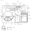
- Fig. 1 is a plan view showing the entire configuration of the automatic analysis device according to this embodiment.
- Fig. 2 is a vertical sectional view schematically showing the configuration of the reagent cool box of Fig. 1 as viewed from the direction of arrow A.
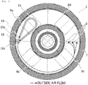
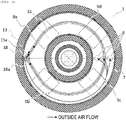
- Fig. 3 is a horizontal sectional view schematically showing the configuration of the reagent cool box of Fig. 2 as viewed from the direction of arrow B.
- the automatic analysis device 100 is a device that causes a specimen and a reagent to react with each other and measures the reaction liquid as a result of the reaction.
- the automatic analysis device 100 includes a reagent cool box 1, a reagent vessel 3, a specimen dispensing nozzle 303, a reaction table 305, a reaction vessel transport mechanism 306, a specimen dispensing tip and reaction vessel holding member 307, a reagent disk 2, a reagent dispensing nozzle 314, a processing unit 315, a detection unit 316, a rack transport line 317, and a control device 319.
- the rack transport line 317 is a line to transport a rack 301 capable of holding a plurality of specimen vessels 302 containing a specimen, to a specimen dispensing position or the like.
- the specimen dispensing nozzle 303 is a nozzle to aspirate the specimen contained in a specimen vessel 302 and discharge it into a reaction vessel 304.
- the reaction table 305 is a disk to induce a reaction between the specimen and reagent at a constant temperature and its temperature is maintained at a prescribed temperature by a heater (not shown) to accelerate the reaction between the specimen and reagent.
- a plurality of reaction vessels 304 are held in the reaction table 305, and a specimen and a reagent are mixed and made to react.
- the reaction vessel transport mechanism 306 transports the reaction vessel 304.
- the specimen dispensing tip and reaction vessel holding member 307 stores a specimen dispensing tip and a reaction vessel 304 that are disposable and used to dispense a specimen.
- the reagent disk 2 is a disk that stores a reagent vessel 3 and is kept cool by the reagent cool box 1 in order to store the reagent stably.
- the user or the reagent vessel transport mechanism (not shown) can access the reagent vessel 3 by opening an opening and closing lid 5 provided on a lid 4.
- a reagent aspiration hole 6 as a through-hole for aspiration of a reagent is provided in part of the lid 4.
- the reagent dispensing nozzle 314 is a nozzle to aspirate the reagent stored in the reagent vessel 3 in the reagent disk 2 through the reagent aspiration hole 6 and discharge it into the reaction vessel 304.
- the reagent vessels 3 in the reagent disk 2 contain various assay reagents (first reagents) that are used for analysis of the specimen.
- the processing unit 315 performs processing before analysis of the specimen by the detection unit 316.
- the detection unit 316 makes detection using the liquid whose reaction has been completed in the reaction vessel 304.
- the control device 319 controls various operations of the above members and also performs arithmetic processing to calculate the concentration of a given component of the specimen from the result of detection by the detection unit 316.
- the control device 319 has a temperature control unit 318 that controls the temperature of the reagent cool box 1.
- the user sets a reagent vessel 3 and consumables such as a specimen dispensing tip and a reaction vessel 304 that are required for analysis, in the reagent disk 2 and the specimen dispensing tip and reaction vessel holding member 307, respectively.
- the reaction vessel transport mechanism 306 of the automatic analysis device transports a reaction vessel 304 and a specimen dispensing tip that are unused, to the reaction table 305 and the specimen dispensing tip mounting position.
- the reagent dispensing nozzle 314 since the reagent dispensing nozzle 314 is installed in a manner to be able to rotate and move up and down, it rotates and moves to above the reagent aspiration hole 6 made in the lid 4 of the reagent cool box 1 and then moves down and passes through the reagent aspiration hole 6. After that, the tip of the reagent dispensing nozzle 314 that has passed through the reagent aspiration hole 6 is inserted into the reagent in a specified reagent vessel 3 to aspirate a specified amount of reagent. Then, the reagent dispensing nozzle 314 moves up and then rotates and moves to above the specified position of the reaction table 305 and discharges the reagent into the reaction vessel 304 set in the reaction table 305.
- reaction refers to binding of a specimen and a luminescent labeled material by antigen-antibody reaction using, as an assay reagent, a luminescent labeled antibody which reacts only with a specific antigen of the specimen.
- the specimen and assay reagent are stirred. After this motion is completed, the used specimen dispensing tip is disposed of into the specimen dispensing tip disposal port 320.
- reaction vessel 304 that has been placed on the reaction table 305 for a prescribed time is transported to the processing unit 315 by a first transport mechanism 308.
- magnetic separation and stirring of the specimen are performed as processing of the specimen before detection.
- the first transport mechanism 308 again transports the reaction vessel 304 to the reaction table 305.
- the reaction vessel 304 that has been placed on the reaction table 305 for the prescribed time is moved to the detection unit 316 by a second transport mechanism 309.
- a signal from the reaction liquid is detected by the detection unit 316 and the result of analysis is given to the user and stored in a memory device.
- reaction vessel 304 is transported to a reaction vessel disposal port 321 by the second transport mechanism 309 and reaction vessel transport mechanism 306 and disposed of.
- the reagent disk 2 is located inside the reagent cool box 1 of the automatic analysis device 100, and a plurality of reagent vessels 3 are placed in the reagent disk 2.
- the shape of the reagent cool box 1 is arbitrary, it is formed cylindrically so that the distance from the inner wall 7 of the reagent cool box 1 on the same circle is uniform.
- the reagent disk 2 is formed so as to be circular in a plan view and the reagent vessels 3 are arranged radially in a circular pattern inside the cylindrical reagent cool box 1. Therefore, as shown in Fig. 2 , when the motor 8 located outside the reagent cool box 1 rotates, the reagent disk 2 rotates in the reagent cool box 1.
- the specified reagent vessel 3 placed on the reagent disk 2 is moved to just below the reagent aspiration hole 6 and in this condition the reagent dispensing nozzle 314 indicated in Fig. 1 aspirates the reagent from the reagent vessel 3 through the reagent aspiration hole 6.
- the reagent aspiration hole 6 is formed in the lid 4 and the outside air and the inside of the reagent cool box 1 are communicated through the reagent aspiration hole 6.
- the reagent aspiration hole 6 through which the reagent dispensing nozzle 314 for aspirating the reagent from the reagent vessel 3 can pass is formed in the lid 4 and the inside and outside of the reagent cool box 1 are communicated through the reagent aspiration hole 6.
- the reagent vessel 3 is kept cool as the cold energy of the cooled inner wall 7 is transferred by air convection or radiation.
- the inner wall 7 is cooled by being directly cooled by a cooler 9 fitted to the outside of the inner wall 7.
- a cooler 9 a device that absorbs heat on one side and radiates heat on the other side by applying an electric current, for example, a Peltier element, may be used. Consequently, the heat in the reagent cool box 1 can be absorbed and the heat can be radiated to the outside of the reagent cool box 1.
- the radiating side of the cooler 9 is an extended heat transfer surface of a heat sink 10.
- the heat sink 10 is air-cooled by forced convection through air blowing by a fan 11 and the exhaust heat is discharged into an exhaust heat duct 12.
- the exhaust heat duct 12 is an air flow path that leads to the outside of the automatic analysis device.
- a water-cooling heat sink or the like that transfers heat by cooling water may be used in order to discharge the heat from the cooler 9.
- the reagent cool box 1 in this embodiment has a plurality of coolers 9a to 9d arranged circumferentially below the bottom surface of the inner wall 7.
- Fig. 2 shows only the cooler 9 on the right side and, for the sake of convenience, the left part of the figure is used to explain the structure of the drain 18, etc. to drain the condensation water generated in the reagent cool box, so the cooler 9 is omitted on the left side in the figure.
- the pipe 15 is arranged to form an outside air introduction path that connects the point of introduction from outside the reagent cool box 1 into the reagent cool box 1 to the drain 18.
- Fig. 1 shows only the cooler 9 on the right side and, for the sake of convenience, the left part of the figure is used to explain the structure of the drain 18, etc. to drain the condensation water generated in the reagent cool box, so the cooler 9 is omitted on the left side in the figure.
- the pipe 15 is arranged to form an outside air introduction path that connects the point of introduction from outside the reagent cool box 1
- the pipe 15 is arranged so that it leads into the reagent cool box 1 by penetrating the bottom surface of the inner wall 7 in an area where no cooler 9 exists, and passes over the cooler 9a among the coolers.
- the pipe 15 passes on the inner diameter side of the drain 18 when it leads into the reagent cool box 1, thereby offering an advantageous effect that the need for making another through-hole in the inner wall 7 is eliminated.
- each of the coolers 9 is measured by a temperature sensor 14 installed near each cooler 9. Using the measured temperature, the temperature of each cooler 9 is controlled by the temperature control unit 318 so that it becomes a preset temperature.
- the temperature of the cooler 9a nearest to a pipe outlet 15a, is set to a temperature lower than the temperature of the other coolers 9b, 9c, and 9d.
- the reagent cool box 1 When the reagent cool box 1 is directly cooled by the cooler 9, if the temperature of the inner wall 7 is uniform in the vertical and horizontal directions, the reagent temperature distribution can be suppressed. For this reason, it is desirable to use a material with a high thermal conductivity such as copper or aluminum as the material of the inner wall 7.
- a cooling fluid path is formed in the inner wall 7 to make the cooling water flow in the path to cool the inner wall 7 so that the air in the reagent cool box 1 and the reagent vessel 3 are cooled.
- a material with a relatively low thermal conductivity such as stainless steel or resin.
- the temperature of the reagent cool box 1 is measured by the temperature sensor 14 fitted inside the reagent cool box 1 or on the inner wall 7. Using the measured temperature, the temperature control unit 318 controls the temperature of the cooler 9 to keep the reagent vessel 3 cool at an adequate temperature.
- the reagent cool box 1 is thermally insulated by a thermal insulation 13 fitted to its outside so that the heat in the reagent cool box 1 hardly escapes outward and the reagent vessel 3 is kept cool efficiently.
- the thermal insulation 13 is made of a material with a low thermal conductivity, for example, expanded polystyrene or expanded polyurethane.
- outside air has a high temperature and a high humidity
- the outside air that has entered through the reagent aspiration hole 6 may cause condensation on the reagent disk 2 or reagent vessel 3.
- outside air is introduced into the reagent cool box 1 to make the pressure in the reagent cool box 1 higher than the atmospheric pressure, so that outside air can be prevented from entering through the reagent aspiration hole.
- condensation on the reagent vessel 3 and reagent disk 2 can be prevented by making the temperature of the introduced outside air lower than the surface temperatures of the reagent vessel 3 and reagent disk 2.
- the air introduced into the reagent cool box 1 is cooled on the pipe 15 and blown out through the pipe outlet 15a. At that time, the condensation water generated in the pipe 15 is also discharged through the pipe outlet 15a.
- the pipe 15 is cooled by being directly fitted to the inner wall 7.
- the pipe outlet 15a functions as an outside air discharge port, but if another member such as an air deflector is connected to the tip of the pipe outlet 15a, the tip of the member functions as an outside air discharge port.
- the blower 16 that is used to supply air should be able to supply air in an environment in which pressure loss is high.
- a diaphragm pump, centrifugal fan or piezo fan may be used.
- the amount of outside air introduced into the reagent cool box 1 should be not smaller than the amount of air that enters the reagent cool box 1 through the reagent aspiration hole and leaks out of the reagent cool box 1.
- condensation on the reagent vessel 3 and reagent disk 2 may cause the condensation water to enter the reagent vessel and affect the analysis performance, condensation must be suppressed. Furthermore, if the condensation generated on the wall surface in the reagent cool box 1 adheres to the surface of the inner wall 7 for a long time, the nature of the condensation water may change.
- the reagent cool box 1 is structured so that the reagent dispensing nozzle intermittently accesses the reagent cool box 1 through the reagent aspiration hole 6 and outside air enters it when the opening and closing lid 5 is opened to take out and put in the reagent vessel 3, even though condensation in the reagent cool box 1 can be reduced, it is difficult to eliminate condensation completely. In other words, it is desirable to prevent condensation on the reagent vessel 3 and reagent disk 2 and immediately discharge the condensation water generated in the reagent cool box 1 and pipe 15 without allowing it to stagnate in the reagent cool box 1.
- the pipe outlet 15a is located near the upper opening unit 18a of the drain 18, the bottom surface of the inner wall 7 of the reagent cool box 1 is inclined at a prescribed angle with respect to the horizontal direction, and the drain 18 is located below the inclined bottom surface of the inner wall 7 of the reagent cool box 1 in the vertical direction.
- the pipe 15 leads into the reagent cool box 1 from outside the reagent cool box 1 by penetrating the heat insulation and inner wall 7 of the reagent cool box 1 and lies along the bottom surface of the inner wall 7 of the reagent cool box 1.
- the pipe outlet 15a located at the tip of the pipe 15, is formed toward the upper opening unit 18a of the drain 18.
- the vertical projection of the pipe outlet 15a may be within the range of the upper opening unit 18a of the drain 18.
- the sectional shape of the pipe 15 can be changed.
- it may be rectangular, circular or, trapezoidal.
- the number of pipes 15 and pipe outlets 15a need not be one; for example, two pipes 15 and two pipe outlets 15a may be provided or two pipe outlets 15a may be provided for one pipe 15.
- the material of the pipe should be a material with a high thermal conductivity, for example, copper or aluminum, so that direct cooling by the cooler through the inner wall 7 can be done easily.
- the inner wall 7 is inclined with respect to the horizontal plane or only the bottom surface of the inner wall 7 is inclined with respect to the horizontal plane.
- the bottom surface of the inner wall 7 is inclined in a manner that only the upper opening unit 18a of the drain 18 is located at the lowermost position. While the bottom surface of the inner wall 7 is inclined with respect to the horizontal direction, the rotation axis of the reagent disk is vertical. This eliminates the need to incline the reagent vessel 3 and the reagent dispensing nozzle.
- the upper end of the drain 18 that is connected to the bottom surface of the inner wall 7 has the upper opening unit 18a that has a larger bore than the bore of the main body of the drain 18.
- the bore diameter is gradually decreased from the upper opening unit 18a to form an inclined surface which is connected to the main body of the drain 18. Therefore, the condensation water on the bottom surface of the inner wall 7 and near the drain 18 is easily guided into the drain 18.
- the outside air introduced by the blower 16 is cooled as it passes through the pipe 15. Since the pipe 15 is fitted along the bottom surface of the reagent cool box 1, the outside air can be cooled to a temperature almost equal to the temperature of the reagent cool box 1. At this time, if the outside air has a high temperature and a high humidity, the temperature of the outside air is cooled and reaches the dew point or lower, and condensation occurs in the pipe 15. The generated condensation water is pushed out by the blower 16 and discharged from the pipe outlet 15a together with the cooled outside air. Since the pipe outlet 15a is formed toward the upper opening unit 18a of the drain 18, the discharged water flows into the upper opening unit 18a of the drain 18 and is immediately discharged without flowing on the other bottom surface of the inner wall 7.
- condensation occurs on the surface of the inner wall 7, if the temperature of the surface of an area having a lower temperature than the outside air discharged into the reagent cool box 1 or the temperature of the outside air that has penetrated when opening and closing the opening and closing lid for replacement of the reagent vessel 3 reaches the dew point or lower, condensation occurs.
- This condensation is guided to the upper opening unit 18a of the drain 18 by the inclined bottom surface of the inner wall 7 of the reagent cool box 1.
- the condensation water is discharged so that it is collected at one point, namely the upper opening unit 18a of the drain 18 that is the lowermost portion of the bottom surface of the inner wall 7. Therefore, the possibility that a certain amount of condensation water stays circularly due to the surface tension is lower than in a reagent cool box whose lowermost portion in the vertical direction is circular when the reagent cool box is viewed from above.
- the condensation water generated on the outer circumferential side of the pipe 15 and on the bottom surface of the inner wall 7 is aspirated toward the outer circumferential surface of the pipe 15 by the capillary force of the clearance between the pipe 15 and the bottom surface of the inner wall 7.
- the condensation water thus aspirated is guided along the outer circumference of the pipe 15 into the upper opening unit 18a of the drain 18.
- the condensation water does not stagnate on the bottom surface of the reagent cool box and the generated condensation water is always discharged into the drain 18, thereby keeping the inside of the reagent cool box 1 hygienic.
- the temperature of the cooler 9a located below the area where the pipe 15 lies is set to a lower temperature than the temperature of the other coolers 9b to 9d. The effect of this is explained below referring to Fig. 4 and Fig. 5 .
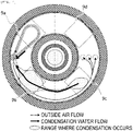
- Fig. 4 is a horizontal sectional view schematically showing a state of condensation when the coolers 9a to 9d have a fixed temperature, as a comparative example.
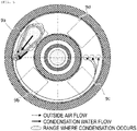
- Fig. 5 is a horizontal sectional view schematically showing a state of condensation when the cooler 9a has a lower temperature than the other coolers 9b to 9d, as in this embodiment.
- the condensation that has occurred in the pipe 15 flows directly into the upper opening unit 18a of the drain 18 that is located near the pipe outlet 15a, and is discharged.
- the temperature of the coolers 9b and 9c is lower than the temperature of the outside air discharged from the pipe outlet 15a, condensation occurs on the coolers 9b and 9c.
- the bottom surface of the inner wall 7 is inclined with the upper opening unit 18a of the drain 18 at the lowermost position, the condensation generated on the coolers 9b and 9c is discharged in a manner that it is collected at one point, namely the upper opening unit 18a.
- the automatic analysis device may include only one cooler that is located in the area where the pipe 15 lies.
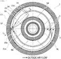
- Fig. 6 is a horizontal sectional view schematically showing the configuration of a reagent cool box according to the second embodiment.
- the pipe 15 is routed so as to encompass the rotation center axis of the reagent disk. Therefore, the pipe 15 in this embodiment lies over all the coolers 9a to 9d. However, the temperature of the cooler 9a, located below the pipe 15's route nearest to the pipe outlet 15a, namely the most downstream side route of the pipe 15, is set to a lower temperature than the temperature of the coolers located below the upstream side route of the pipe 15, namely coolers 9b to 9d.
- Fig. 7 is a horizontal sectional view schematically showing the configuration of a reagent cool box according to the third embodiment.
- Fig. 8 is a vertical sectional view schematically showing the configuration of the reagent cool box of Fig. 7 as viewed from the direction of arrow C.
- the pipe outlet 15a is located near the cooler 9a in the reagent cool box 1 and an explanation is given below of the case that a drain groove 20 and a cover 21 lie over the cooler 9a. Therefore, the different elements from the elements of the reagent cool box 1 in the above embodiments are described below and description of the same elements is omitted.
- the pipe outlet 15a is located near the cooler 9b and the bottom surface of the inner wall 7 and the cover 21 over it are located so as to form a flow path that connects the pipe outlet 15a to the upper opening unit 18a of the drain 18.
- a cover opening end 21a and the bottom surface of the inner wall 7 form an outside air discharge port.
- an outside air introduction path is formed by the pipe 15 on the upstream side and formed by the cover 21 and the bottom surface of the inner wall 7 on the downstream side.
- the drain groove 20, which is lower than the other portions of the bottom surface of the inner wall 7, is located on the bottom surface of the inner wall 7 in the area where the cover 21 is located.
- the drain groove 20 is inclined so that the upper opening unit 18a of the drain 18 becomes the lowermost portion.
- the shape of the drain groove 20 is not limited as far as it is inclined so that the upper opening unit 18a is the lowermost portion.
- a fin shape to increase the area of contact between outside air and the inner wall 7 may be provided over the drain groove 20.
- a labyrinth flow path may be formed to increase the length of contact between outside air and the inner wall 7.
- Fig. 9 is a horizontal sectional view schematically showing a state of occurrence of condensation in this embodiment.
- the outside air introduced by the pipe 15 enters the cover 21 from the pipe outlet 15a and passes through the outside air introduction path constituted by the clearance between the drain groove 20 and cover 21 and is discharged from the outside air discharge port at the tip of the cover 21 toward the upper opening unit 18a into the reagent cool box 1.
- the generated condensation water passes through the drain groove 20 and is discharged into the upper opening unit 18a of the drain 18.
- the distance between the surface of the drain groove 20 and the cooler 9a in the thickness direction is smaller than in the areas where the other coolers 9b, 9c, and 9d are installed, the surface temperature on the drain groove 20 over the cooler 9a is lower than over the coolers 9b, 9c, and 9d.
- the temperature of the outside air discharged from near the drain 18 into the reagent cool box 1 is lower than the surface temperature of the inner wall 7 over the coolers 9b, 9c, and 9d, so occurrence of condensation in the reagent cool box 1 can be suppressed more effectively than in the first and second embodiments.
- the area over the cooler 9a which is lowest in temperature and likely to cause condensation, the area of contact with the bottom surface of the inner wall 7 is larger and the outside air-cooling efficiency is higher, so condensation can be concentrated on this area and thus condensation in the other areas of the bottom surface of the inner wall 7 can be suppressed.
- the same effect can also be achieved by making the temperature of the cooler 9a lower than the temperature of the other coolers 9b, 9c, and 9d.
- the present invention is not limited to the above embodiments but includes many types of variations.
- An element of an embodiment may be replaced by an element of another embodiment or an element of an embodiment may be added to another embodiment. Also, for some elements of each embodiment, addition, deletion, or replacement of elements can be made.
Landscapes
- Chemical & Material Sciences (AREA)
- Health & Medical Sciences (AREA)
- General Health & Medical Sciences (AREA)
- Life Sciences & Earth Sciences (AREA)
- Analytical Chemistry (AREA)
- Biochemistry (AREA)
- Physics & Mathematics (AREA)
- General Physics & Mathematics (AREA)
- Immunology (AREA)
- Pathology (AREA)
- Clinical Laboratory Science (AREA)
- Chemical Kinetics & Catalysis (AREA)
- Automatic Analysis And Handling Materials Therefor (AREA)
Abstract
Description
- The present invention relates to an automatic analysis device.
- In recent years, an automatic analysis device that analyzes a specimen (sample) such as blood or urine biochemically or immunologically has been known. Generally, analysis is made by causing a specimen and a reagent to react with each other, in which the reaction between the reagent and specimen is optically and electrically detected.
- In this type of automatic analysis device, each of the reagents that are used for reaction is put in a vessel and the vessel is placed in the reagent setting area of a reagent cool box. The inside of the reagent cool box is kept cool, for example, at a temperature of 5°C to 12°C or so.
- Usually, in the automatic analysis device, the reagent cool box has a through-hole for aspiration of a reagent in order to aspirate the reagent from a reagent vessel set in the reagent cool box. As outside air with high temperature and humidity enters the cool box from the through-hole, the following problem may arise: the temperature inside the reagent cool box rises or the inflowing outside air is cooled to below the dew point, resulting in condensation in the cool box. The rise in the temperature inside the cool box is undesirable in terms of stable storage of the reagent and also condensation in the reagent cool box may cause penetration of the condensation water into the reagent vessel and change the condition of the reagent. In addition, a tag for reagent identification may be attached to the reagent vessel and in that case, the tag may be damaged due to adhesion of the condensation water to the tag.
- As a solution to these problems,
Patent Literature 1 proposes an automatic analysis device that directly introduces cooled air into a reagent cool box to make the pressure inside the cool box not lower than the atmospheric pressure, so that cool air blows out from a reagent aspiration hole to prevent influx of outside air through the reagent aspiration hole and thereby suppress condensation inside the reagent cool box. - Patent Literature 1:
Japanese Patent Application Laid-Open No. 2013-185980 - In the reagent cool box described in
Patent Literature 1, if the air introduced from the cooled air introduction path into the reagent cool box contains moisture, condensation might occur inside the reagent cool box and cause the generated condensation water to stagnate on the bottom surface of the inner wall of the reagent cool box. - The object of the present invention is to provide an automatic analysis device that can suppress condensation inside the reagent cool box and immediately discharge the generated condensation water by introducing outside air.
- In order to solve the above problem, according to the present invention, an automatic analysis device includes a reagent cool box that stores a plurality of reagent vessels while keeping the plurality of reagent vessels cool, in which the reagent cool box includes: a drain for discharging the condensation water generated inside the reagent cool box, and an outside air introduction path for guiding air outside the reagent cool box to the inside, and the outside air introduction path is provided along the bottom surface of the reagent cool box, and an outside air discharge port thereof is formed toward an upper opening unit of the drain.
- According to the present invention, there is provided an automatic analysis device that can suppress occurrence of condensation inside a reagent cool box and can immediately discharge the condensation water generated by introducing outside air.
-
- [
Fig. 1] Fig. 1 is a plan view showing the entire configuration of an automatic analysis device according to Example 1. - [
Fig. 2] Fig. 2 is a vertical sectional view showing a schematic configuration of the reagent cool box ofFig. 1 as viewed from the direction of arrow A. - [
Fig. 3] Fig. 3 is a horizontal sectional view showing a schematic configuration of the reagent cool box ofFig. 2 as viewed from the direction of arrow B. - [
Fig. 4] Fig. 4 is a horizontal sectional view schematically showing a state of occurrence of condensation and a flow of condensation water in a comparative example. - [
Fig. 5] Fig. 5 is a horizontal sectional view schematically showing a state of occurrence of condensation and a flow of condensation water in Example 1. - [
Fig. 6] Fig. 6 is a horizontal sectional view showing a schematic configuration of a reagent cool box according to Example 2. - [
Fig. 7] Fig. 7 is a horizontal sectional view showing a schematic configuration of a reagent cool box according to Example 3. - [
Fig. 8] Fig. 8 is a vertical sectional view showing a schematic configuration of the reagent cool box ofFig. 7 as viewed from the direction of arrow C. - [
Fig. 9] Fig. 9 is a horizontal sectional view schematically showing a state of occurrence of condensation and a flow of condensation water in Example 3. - Hereinafter, embodiments of the present invention will be described in detail referring to drawings.
- The automatic analysis device according to this embodiment will be described referring to
Fig. 1 to Fig. 5 . First, the entire configuration of the automatic analysis device according to this embodiment will be described referring toFig. 1 to Fig. 3 .Fig. 1 is a plan view showing the entire configuration of the automatic analysis device according to this embodiment.Fig. 2 is a vertical sectional view schematically showing the configuration of the reagent cool box ofFig. 1 as viewed from the direction of arrow A.Fig. 3 is a horizontal sectional view schematically showing the configuration of the reagent cool box ofFig. 2 as viewed from the direction of arrow B. - As shown in
Fig. 1 , theautomatic analysis device 100 according to this embodiment is a device that causes a specimen and a reagent to react with each other and measures the reaction liquid as a result of the reaction. Theautomatic analysis device 100 includes a reagentcool box 1, areagent vessel 3, aspecimen dispensing nozzle 303, a reaction table 305, a reactionvessel transport mechanism 306, a specimen dispensing tip and reactionvessel holding member 307, areagent disk 2, areagent dispensing nozzle 314, aprocessing unit 315, adetection unit 316, arack transport line 317, and acontrol device 319. - Here, the
rack transport line 317 is a line to transport arack 301 capable of holding a plurality ofspecimen vessels 302 containing a specimen, to a specimen dispensing position or the like. Thespecimen dispensing nozzle 303 is a nozzle to aspirate the specimen contained in aspecimen vessel 302 and discharge it into areaction vessel 304. The reaction table 305 is a disk to induce a reaction between the specimen and reagent at a constant temperature and its temperature is maintained at a prescribed temperature by a heater (not shown) to accelerate the reaction between the specimen and reagent. A plurality ofreaction vessels 304 are held in the reaction table 305, and a specimen and a reagent are mixed and made to react. The reactionvessel transport mechanism 306 transports thereaction vessel 304. The specimen dispensing tip and reactionvessel holding member 307 stores a specimen dispensing tip and areaction vessel 304 that are disposable and used to dispense a specimen. Thereagent disk 2 is a disk that stores areagent vessel 3 and is kept cool by the reagentcool box 1 in order to store the reagent stably. The user or the reagent vessel transport mechanism (not shown) can access thereagent vessel 3 by opening an opening and closinglid 5 provided on alid 4. Areagent aspiration hole 6 as a through-hole for aspiration of a reagent is provided in part of thelid 4. Thereagent dispensing nozzle 314 is a nozzle to aspirate the reagent stored in thereagent vessel 3 in thereagent disk 2 through thereagent aspiration hole 6 and discharge it into thereaction vessel 304. Thereagent vessels 3 in thereagent disk 2 contain various assay reagents (first reagents) that are used for analysis of the specimen. Theprocessing unit 315 performs processing before analysis of the specimen by thedetection unit 316. Thedetection unit 316 makes detection using the liquid whose reaction has been completed in thereaction vessel 304. Thecontrol device 319 controls various operations of the above members and also performs arithmetic processing to calculate the concentration of a given component of the specimen from the result of detection by thedetection unit 316. Thecontrol device 319 has atemperature control unit 318 that controls the temperature of the reagentcool box 1. - Next, the overall flow of analysis in the automatic analysis device according to this embodiment will be briefly outlined. Before analysis, the user sets a
reagent vessel 3 and consumables such as a specimen dispensing tip and areaction vessel 304 that are required for analysis, in thereagent disk 2 and the specimen dispensing tip and reactionvessel holding member 307, respectively. - First, the user loads the
rack 301 in the automatic analysis device with the object of analysis such as blood or urine put in thespecimen vessel 302. At this time, the reactionvessel transport mechanism 306 of the automatic analysis device transports areaction vessel 304 and a specimen dispensing tip that are unused, to the reaction table 305 and the specimen dispensing tip mounting position. - After that, since the
reagent dispensing nozzle 314 is installed in a manner to be able to rotate and move up and down, it rotates and moves to above thereagent aspiration hole 6 made in thelid 4 of the reagentcool box 1 and then moves down and passes through thereagent aspiration hole 6. After that, the tip of thereagent dispensing nozzle 314 that has passed through thereagent aspiration hole 6 is inserted into the reagent in a specifiedreagent vessel 3 to aspirate a specified amount of reagent. Then, thereagent dispensing nozzle 314 moves up and then rotates and moves to above the specified position of the reaction table 305 and discharges the reagent into thereaction vessel 304 set in the reaction table 305. - Then, as the
rack 301 passes through therack transport line 317 and reaches the specimen dispensing position, a specimen dispensing tip is mounted on thespecimen dispensing nozzle 303 to dispense the specimen from thespecimen vessel 302 into thereaction vessel 304, so that reaction between the specimen and assay reagent is started. Here, reaction refers to binding of a specimen and a luminescent labeled material by antigen-antibody reaction using, as an assay reagent, a luminescent labeled antibody which reacts only with a specific antigen of the specimen. In this case, as the mixture of the specimen and assay reagent is aspirated and discharged in the specimen dispensing tip, the specimen and assay reagent are stirred. After this motion is completed, the used specimen dispensing tip is disposed of into the specimen dispensingtip disposal port 320. - After the reaction between the specimen and assay reagent is started by stirring, in some cases another reagent is further added at a specific timing to induce a reaction. For example, there is a process in which a magnetic bead with an antibody bound to its surface is further bound to the above antigen. For the process, the
reaction vessel 304 that has been placed on the reaction table 305 for a prescribed time is transported to theprocessing unit 315 by afirst transport mechanism 308. In theprocessing unit 315, magnetic separation and stirring of the specimen are performed as processing of the specimen before detection. - After the preprocessing process is ended, the
first transport mechanism 308 again transports thereaction vessel 304 to the reaction table 305. - Regardless of whether magnetic separation has been performed or not, the
reaction vessel 304 that has been placed on the reaction table 305 for the prescribed time is moved to thedetection unit 316 by asecond transport mechanism 309. A signal from the reaction liquid is detected by thedetection unit 316 and the result of analysis is given to the user and stored in a memory device. - After the detection is completed, the
reaction vessel 304 is transported to a reactionvessel disposal port 321 by thesecond transport mechanism 309 and reactionvessel transport mechanism 306 and disposed of. - Next, details of the structure of the reagent
cool box 1 will be described referring toFig. 2 andFig. 3 . - The
reagent disk 2 is located inside the reagentcool box 1 of theautomatic analysis device 100, and a plurality ofreagent vessels 3 are placed in thereagent disk 2. Although the shape of the reagentcool box 1 is arbitrary, it is formed cylindrically so that the distance from theinner wall 7 of the reagentcool box 1 on the same circle is uniform. Also, thereagent disk 2 is formed so as to be circular in a plan view and thereagent vessels 3 are arranged radially in a circular pattern inside the cylindrical reagentcool box 1. Therefore, as shown inFig. 2 , when themotor 8 located outside the reagentcool box 1 rotates, thereagent disk 2 rotates in the reagentcool box 1. - Consequently, the specified
reagent vessel 3 placed on thereagent disk 2 is moved to just below thereagent aspiration hole 6 and in this condition thereagent dispensing nozzle 314 indicated inFig. 1 aspirates the reagent from thereagent vessel 3 through thereagent aspiration hole 6. As shown inFig. 2 , thereagent aspiration hole 6 is formed in thelid 4 and the outside air and the inside of the reagentcool box 1 are communicated through thereagent aspiration hole 6. In other words, thereagent aspiration hole 6 through which thereagent dispensing nozzle 314 for aspirating the reagent from thereagent vessel 3 can pass is formed in thelid 4 and the inside and outside of the reagentcool box 1 are communicated through thereagent aspiration hole 6. - Basically, the
reagent vessel 3 is kept cool as the cold energy of the cooledinner wall 7 is transferred by air convection or radiation. - The
inner wall 7 is cooled by being directly cooled by acooler 9 fitted to the outside of theinner wall 7. As thecooler 9, a device that absorbs heat on one side and radiates heat on the other side by applying an electric current, for example, a Peltier element, may be used. Consequently, the heat in the reagentcool box 1 can be absorbed and the heat can be radiated to the outside of the reagentcool box 1. The radiating side of thecooler 9 is an extended heat transfer surface of aheat sink 10. Theheat sink 10 is air-cooled by forced convection through air blowing by afan 11 and the exhaust heat is discharged into anexhaust heat duct 12. Theexhaust heat duct 12 is an air flow path that leads to the outside of the automatic analysis device. Instead of using theheat sink 10 andfan 11, for example, a water-cooling heat sink or the like that transfers heat by cooling water may be used in order to discharge the heat from thecooler 9. - The reagent
cool box 1 in this embodiment has a plurality ofcoolers 9a to 9d arranged circumferentially below the bottom surface of theinner wall 7.Fig. 2 shows only thecooler 9 on the right side and, for the sake of convenience, the left part of the figure is used to explain the structure of thedrain 18, etc. to drain the condensation water generated in the reagent cool box, so thecooler 9 is omitted on the left side in the figure. Thepipe 15 is arranged to form an outside air introduction path that connects the point of introduction from outside the reagentcool box 1 into the reagentcool box 1 to thedrain 18. In addition, as shown inFig. 3 , thepipe 15 is arranged so that it leads into the reagentcool box 1 by penetrating the bottom surface of theinner wall 7 in an area where nocooler 9 exists, and passes over the cooler 9a among the coolers. Particularly, thepipe 15 passes on the inner diameter side of thedrain 18 when it leads into the reagentcool box 1, thereby offering an advantageous effect that the need for making another through-hole in theinner wall 7 is eliminated. - The temperature of each of the
coolers 9 is measured by atemperature sensor 14 installed near eachcooler 9. Using the measured temperature, the temperature of eachcooler 9 is controlled by thetemperature control unit 318 so that it becomes a preset temperature. Here, the temperature of the cooler 9a, nearest to apipe outlet 15a, is set to a temperature lower than the temperature of theother coolers - When the reagent
cool box 1 is directly cooled by thecooler 9, if the temperature of theinner wall 7 is uniform in the vertical and horizontal directions, the reagent temperature distribution can be suppressed. For this reason, it is desirable to use a material with a high thermal conductivity such as copper or aluminum as the material of theinner wall 7. Instead of adopting the direct cooling method that uses thecooler 9 to cool theinner wall 7, the following method can be adopted: a cooling fluid path is formed in theinner wall 7 to make the cooling water flow in the path to cool theinner wall 7 so that the air in the reagentcool box 1 and thereagent vessel 3 are cooled. In this case, since the temperature distribution of theinner wall 7 depends on the temperature distribution of the cooling water, it is also possible to use a material with a relatively low thermal conductivity such as stainless steel or resin. - The temperature of the reagent
cool box 1 is measured by thetemperature sensor 14 fitted inside the reagentcool box 1 or on theinner wall 7. Using the measured temperature, thetemperature control unit 318 controls the temperature of thecooler 9 to keep thereagent vessel 3 cool at an adequate temperature. - The reagent
cool box 1 is thermally insulated by athermal insulation 13 fitted to its outside so that the heat in the reagentcool box 1 hardly escapes outward and thereagent vessel 3 is kept cool efficiently. Preferably, thethermal insulation 13 is made of a material with a low thermal conductivity, for example, expanded polystyrene or expanded polyurethane. - If the outside air has a high temperature and a high humidity, the outside air that has entered through the
reagent aspiration hole 6 may cause condensation on thereagent disk 2 orreagent vessel 3. For this reason, outside air is introduced into the reagentcool box 1 to make the pressure in the reagentcool box 1 higher than the atmospheric pressure, so that outside air can be prevented from entering through the reagent aspiration hole. Also, condensation on thereagent vessel 3 andreagent disk 2 can be prevented by making the temperature of the introduced outside air lower than the surface temperatures of thereagent vessel 3 andreagent disk 2. - The air introduced into the reagent
cool box 1 is cooled on thepipe 15 and blown out through thepipe outlet 15a. At that time, the condensation water generated in thepipe 15 is also discharged through thepipe outlet 15a. Thepipe 15 is cooled by being directly fitted to theinner wall 7. In this embodiment, thepipe outlet 15a functions as an outside air discharge port, but if another member such as an air deflector is connected to the tip of thepipe outlet 15a, the tip of the member functions as an outside air discharge port. - Furthermore, when the flow path for outside air to flow in the
pipe 15 is longer, the time and area of contact between thepipe 15 and outside air increase and thus the temperature reached by the outside air introduced into the reagentcool box 1 is lower. In other words, in order to prevent condensation on theregent vessel 3 andreagent disk 2, it is desirable to design the flow path length of thepipe 15 so that the temperature of the air discharged from thepipe outlet 15a is lower than the temperature of the reagent disk andreagent vessel 3. - When the flow path of the
pipe 15 is longer, pressure loss is increased, so preferably theblower 16 that is used to supply air should be able to supply air in an environment in which pressure loss is high. For example, a diaphragm pump, centrifugal fan or piezo fan may be used. In addition, it is desirable to install a filter or the like before the point of introduction of outside air in order to prevent dust or bacteria from entering the reagentcool box 1. - It is desirable that the amount of outside air introduced into the reagent
cool box 1 should be not smaller than the amount of air that enters the reagentcool box 1 through the reagent aspiration hole and leaks out of the reagentcool box 1. However, in order to reduce the amount of heat loss caused by introduction of outside air and enhance the cooling efficiency, it is desirable to avoid increasing the amount of introduced outside air more than necessary. - Next, discharge of condensation water in this embodiment will be explained in detail.
- As mentioned above, since condensation on the
reagent vessel 3 andreagent disk 2 may cause the condensation water to enter the reagent vessel and affect the analysis performance, condensation must be suppressed. Furthermore, if the condensation generated on the wall surface in the reagentcool box 1 adheres to the surface of theinner wall 7 for a long time, the nature of the condensation water may change. - However, since the reagent
cool box 1 is structured so that the reagent dispensing nozzle intermittently accesses the reagentcool box 1 through thereagent aspiration hole 6 and outside air enters it when the opening and closinglid 5 is opened to take out and put in thereagent vessel 3, even though condensation in the reagentcool box 1 can be reduced, it is difficult to eliminate condensation completely. In other words, it is desirable to prevent condensation on thereagent vessel 3 andreagent disk 2 and immediately discharge the condensation water generated in the reagentcool box 1 andpipe 15 without allowing it to stagnate in the reagentcool box 1. - Therefore, in this embodiment, the
pipe outlet 15a is located near theupper opening unit 18a of thedrain 18, the bottom surface of theinner wall 7 of the reagentcool box 1 is inclined at a prescribed angle with respect to the horizontal direction, and thedrain 18 is located below the inclined bottom surface of theinner wall 7 of the reagentcool box 1 in the vertical direction. - Next, the structures of the bottom surface of the reagent
cool box 1, thedrain 18, thepipe outlet 15a, and thepipe 15 will be explained in detail. - The
pipe 15 leads into the reagentcool box 1 from outside the reagentcool box 1 by penetrating the heat insulation andinner wall 7 of the reagentcool box 1 and lies along the bottom surface of theinner wall 7 of the reagentcool box 1. Thepipe outlet 15a, located at the tip of thepipe 15, is formed toward theupper opening unit 18a of thedrain 18. The vertical projection of thepipe outlet 15a may be within the range of theupper opening unit 18a of thedrain 18. - The sectional shape of the
pipe 15 can be changed. For example, it may be rectangular, circular or, trapezoidal. The number ofpipes 15 andpipe outlets 15a need not be one; for example, twopipes 15 and twopipe outlets 15a may be provided or twopipe outlets 15a may be provided for onepipe 15. Preferably, the material of the pipe should be a material with a high thermal conductivity, for example, copper or aluminum, so that direct cooling by the cooler through theinner wall 7 can be done easily. - Regarding the bottom surface of the
inner wall 7, theinner wall 7 is inclined with respect to the horizontal plane or only the bottom surface of theinner wall 7 is inclined with respect to the horizontal plane. The bottom surface of theinner wall 7 is inclined in a manner that only theupper opening unit 18a of thedrain 18 is located at the lowermost position. While the bottom surface of theinner wall 7 is inclined with respect to the horizontal direction, the rotation axis of the reagent disk is vertical. This eliminates the need to incline thereagent vessel 3 and the reagent dispensing nozzle. - There is no restriction on the shape of the bottom surface of the
inner wall 7 and it may have a groove or projection. However, it is desirable that the surface of the groove or projection should be inclined with respect to the horizontal direction or the direction in which thedrain 18 is installed. The upper end of thedrain 18 that is connected to the bottom surface of theinner wall 7 has theupper opening unit 18a that has a larger bore than the bore of the main body of thedrain 18. The bore diameter is gradually decreased from theupper opening unit 18a to form an inclined surface which is connected to the main body of thedrain 18. Therefore, the condensation water on the bottom surface of theinner wall 7 and near thedrain 18 is easily guided into thedrain 18. - Next, the advantageous effects of the automatic analysis device according to this embodiment will be explained.
- The outside air introduced by the
blower 16 is cooled as it passes through thepipe 15. Since thepipe 15 is fitted along the bottom surface of the reagentcool box 1, the outside air can be cooled to a temperature almost equal to the temperature of the reagentcool box 1. At this time, if the outside air has a high temperature and a high humidity, the temperature of the outside air is cooled and reaches the dew point or lower, and condensation occurs in thepipe 15. The generated condensation water is pushed out by theblower 16 and discharged from thepipe outlet 15a together with the cooled outside air. Since thepipe outlet 15a is formed toward theupper opening unit 18a of thedrain 18, the discharged water flows into theupper opening unit 18a of thedrain 18 and is immediately discharged without flowing on the other bottom surface of theinner wall 7. - Furthermore, on the surface of the
inner wall 7, if the temperature of the surface of an area having a lower temperature than the outside air discharged into the reagentcool box 1 or the temperature of the outside air that has penetrated when opening and closing the opening and closing lid for replacement of thereagent vessel 3 reaches the dew point or lower, condensation occurs. This condensation is guided to theupper opening unit 18a of thedrain 18 by the inclined bottom surface of theinner wall 7 of the reagentcool box 1. Here, the condensation water is discharged so that it is collected at one point, namely theupper opening unit 18a of thedrain 18 that is the lowermost portion of the bottom surface of theinner wall 7. Therefore, the possibility that a certain amount of condensation water stays circularly due to the surface tension is lower than in a reagent cool box whose lowermost portion in the vertical direction is circular when the reagent cool box is viewed from above. - Furthermore, since the
pipe 15 is located in contact with or adjacent to the bottom surface of theinner wall 7, the condensation water generated on the outer circumferential side of thepipe 15 and on the bottom surface of theinner wall 7 is aspirated toward the outer circumferential surface of thepipe 15 by the capillary force of the clearance between thepipe 15 and the bottom surface of theinner wall 7. The condensation water thus aspirated is guided along the outer circumference of thepipe 15 into theupper opening unit 18a of thedrain 18. - Consequently, the condensation water does not stagnate on the bottom surface of the reagent cool box and the generated condensation water is always discharged into the
drain 18, thereby keeping the inside of the reagentcool box 1 hygienic. - In addition, in this embodiment, among the plurality of
coolers 9, the temperature of the cooler 9a located below the area where thepipe 15 lies is set to a lower temperature than the temperature of theother coolers 9b to 9d. The effect of this is explained below referring toFig. 4 andFig. 5 . -
Fig. 4 is a horizontal sectional view schematically showing a state of condensation when thecoolers 9a to 9d have a fixed temperature, as a comparative example.Fig. 5 is a horizontal sectional view schematically showing a state of condensation when the cooler 9a has a lower temperature than theother coolers 9b to 9d, as in this embodiment. - In
Fig. 4 , the condensation that has occurred in thepipe 15 flows directly into theupper opening unit 18a of thedrain 18 that is located near thepipe outlet 15a, and is discharged. Here, if the temperature of thecoolers pipe outlet 15a, condensation occurs on thecoolers inner wall 7 is inclined with theupper opening unit 18a of thedrain 18 at the lowermost position, the condensation generated on thecoolers upper opening unit 18a. - On the other hand, in this embodiment, since the temperature of the discharged outside air is lower than the temperature of the bottom surface of the
inner wall 7 over thecoolers coolers Fig. 5 . Consequently, the range of occurrence of condensation can be restricted to the area around the cooler 9a and theupper opening unit 18a of thedrain 18, thereby making it easier to keep most areas of the inside of the reagentcool box 1 hygienic. - Although a plurality of coolers are provided in this embodiment, the automatic analysis device may include only one cooler that is located in the area where the
pipe 15 lies. - Next, the second embodiment will be described referring to
Fig. 6. Fig. 6 is a horizontal sectional view schematically showing the configuration of a reagent cool box according to the second embodiment. - In the second embodiment, as shown in
Fig. 6 , thepipe 15 is routed so as to encompass the rotation center axis of the reagent disk. Therefore, thepipe 15 in this embodiment lies over all thecoolers 9a to 9d. However, the temperature of the cooler 9a, located below thepipe 15's route nearest to thepipe outlet 15a, namely the most downstream side route of thepipe 15, is set to a lower temperature than the temperature of the coolers located below the upstream side route of thepipe 15, namelycoolers 9b to 9d. - Next, the advantageous effects of the automatic analysis device according to this embodiment will be explained. In this embodiment, since the route of the
pipe 15 lying on the bottom surface of theinner wall 7 is long, the outside air introduced by theblower 16 is sufficiently cooled as it passes through thepipe 15. Therefore, the temperature of the outside air discharged from thepipe outlet 15a into the reagentcool box 1 can be easily made close to the temperature of the reagentcool box 1 and thus condensation on thereagent vessel 3 andreagent disk 2 can be prevented. -
Fig. 7 is a horizontal sectional view schematically showing the configuration of a reagent cool box according to the third embodiment.Fig. 8 is a vertical sectional view schematically showing the configuration of the reagent cool box ofFig. 7 as viewed from the direction of arrow C. - In this embodiment, the
pipe outlet 15a is located near the cooler 9a in the reagentcool box 1 and an explanation is given below of the case that adrain groove 20 and acover 21 lie over the cooler 9a. Therefore, the different elements from the elements of the reagentcool box 1 in the above embodiments are described below and description of the same elements is omitted. - In the reagent
cool box 1 in this embodiment, thepipe outlet 15a is located near the cooler 9b and the bottom surface of theinner wall 7 and thecover 21 over it are located so as to form a flow path that connects thepipe outlet 15a to theupper opening unit 18a of thedrain 18. And acover opening end 21a and the bottom surface of theinner wall 7 form an outside air discharge port. Thus, in this embodiment, an outside air introduction path is formed by thepipe 15 on the upstream side and formed by thecover 21 and the bottom surface of theinner wall 7 on the downstream side. Thedrain groove 20, which is lower than the other portions of the bottom surface of theinner wall 7, is located on the bottom surface of theinner wall 7 in the area where thecover 21 is located. - The
drain groove 20 is inclined so that theupper opening unit 18a of thedrain 18 becomes the lowermost portion. The shape of thedrain groove 20 is not limited as far as it is inclined so that theupper opening unit 18a is the lowermost portion. For example, a fin shape to increase the area of contact between outside air and theinner wall 7 may be provided over thedrain groove 20. Alternatively, using thedrain groove 20 andcover 21, a labyrinth flow path may be formed to increase the length of contact between outside air and theinner wall 7. - Next, the advantageous effects of this embodiment will be explained referring to
Fig. 9. Fig. 9 is a horizontal sectional view schematically showing a state of occurrence of condensation in this embodiment. - The outside air introduced by the
pipe 15 enters thecover 21 from thepipe outlet 15a and passes through the outside air introduction path constituted by the clearance between thedrain groove 20 andcover 21 and is discharged from the outside air discharge port at the tip of thecover 21 toward theupper opening unit 18a into the reagentcool box 1. The generated condensation water passes through thedrain groove 20 and is discharged into theupper opening unit 18a of thedrain 18. Here, since the distance between the surface of thedrain groove 20 and the cooler 9a in the thickness direction is smaller than in the areas where theother coolers drain groove 20 over the cooler 9a is lower than over thecoolers drain 18 into the reagentcool box 1 is lower than the surface temperature of theinner wall 7 over thecoolers cool box 1 can be suppressed more effectively than in the first and second embodiments. In addition, in the area over the cooler 9a, which is lowest in temperature and likely to cause condensation, the area of contact with the bottom surface of theinner wall 7 is larger and the outside air-cooling efficiency is higher, so condensation can be concentrated on this area and thus condensation in the other areas of the bottom surface of theinner wall 7 can be suppressed. - In this embodiment, the same effect can also be achieved by making the temperature of the cooler 9a lower than the temperature of the
other coolers - The present invention is not limited to the above embodiments but includes many types of variations. An element of an embodiment may be replaced by an element of another embodiment or an element of an embodiment may be added to another embodiment. Also, for some elements of each embodiment, addition, deletion, or replacement of elements can be made.
-
- 1: reagent cool box
- 2: reagent disk
- 3: reagent vessel
- 4: lid
- 5: opening and closing lid
- 6: reagent suction hole
- 7: inner wall
- 8: motor
- 9: cooler
- 10: heat sink
- 11: fan
- 12: exhaust heat duct
- 13: thermal insulation
- 14: temperature sensor
- 15: pipe
- 15a: pipe outlet
- 16: blower
- 18: drain
- 18a: upper opening unit of drain
- 20: drain groove
- 21: cover
- 21a: cover opening end
- 100: automatic analysis device
- 301: rack
- 302: specimen vessel
- 303: specimen dispensing nozzle
- 304: reaction vessel
- 305: reaction table
- 306: reaction vessel transport mechanism
- 307: specimen dispensing tip and reaction vessel holding member
- 308: first transport mechanism
- 309: second transport mechanism
- 314: reagent dispensing nozzle
- 315: processing unit
- 316: detection unit
- 317: rack transport line
- 318: temperature control unit
- 319: control device
- 320: specimen dispensing tip disposal port
- 321: reaction vessel disposal port
Claims (7)
- An automatic analysis device comprising a reagent cool box that stores a plurality of reagent vessels while keeping the plurality of reagent vessels cool, wherein
the reagent cool box includes:a drain for discharging the condensation water generated inside the reagent cool box, andan outside air introduction path for guiding air outside the reagent cool box to the inside, andthe outside air introduction path is provided along a bottom surface of the reagent cool box, and an outside air discharge port thereof is formed toward an upper opening unit of the drain. - An automatic analysis device comprising a reagent cool box that stores a plurality of reagent vessels while keeping the plurality of reagent vessels cool, wherein
the reagent cool box includes:a drain for discharging the condensation water generated inside the reagent cool box, andan outside air introduction path that guides air outside the reagent cool box to the inside, andthe outside air introduction path is provided along a bottom surface of the reagent cool box, and a vertical projection of an outside air discharge port thereof is within a range of an upper opening unit of the drain. - An automatic analysis device comprising a reagent cool box that stores a plurality of reagent vessels while keeping the plurality of reagent vessels cool, wherein
the reagent cool box includes:a drain for discharging the condensation water generated inside the reagent cool box, andan outside air introduction path that guides air outside the reagent cool box to the inside,the inner wall surface of the reagent cool box is inclined, andan upper opening unit of the drain is located at a lowermost portion of the bottom surface of the inner wall of the reagent cool box. - An automatic analysis device comprising a reagent cool box that stores a plurality of reagent vessels while keeping the plurality of reagent vessels cool, wherein
the reagent cool box includes:a drain for discharging the condensation water generated inside the reagent cool box,an outside air introduction path that guides the air outside the reagent cool box to the inside, anda plurality of coolers provided below the bottom surface of the inner wall of the reagent cool box, andthe cooler located below the air introduction path on the most downstream side is set to a lower temperature than the other coolers. - The automatic analysis device according to any one of claims 1 to 4, wherein
the outside air introduction path is located on an inner diameter side of the drain. - The automatic analysis device according to any one of claims 1 to 4, whereinthe upstream side of the outside air introduction path is formed by a pipe guiding from the outside of the reagent cool box to the inside, the downstream side thereof is formed by the bottom surface of the inner wall of the reagent cool box and a cover provided thereabove, andthe outside air discharge port is formed at an opening end of the cover.
- The automatic analysis device according to claim 6, wherein
the bottom surface of the inner wall located below the cover is provided with a drain groove that is lower than the bottom surfaces of the other inner walls.
Applications Claiming Priority (2)
| Application Number | Priority Date | Filing Date | Title |
|---|---|---|---|
| JP2020041724 | 2020-03-11 | ||
| PCT/JP2021/006240 WO2021182068A1 (en) | 2020-03-11 | 2021-02-19 | Automated analyzer |
Publications (2)
| Publication Number | Publication Date |
|---|---|
| EP4119949A1 true EP4119949A1 (en) | 2023-01-18 |
| EP4119949A4 EP4119949A4 (en) | 2024-07-17 |
Family
ID=77671667
Family Applications (1)
| Application Number | Title | Priority Date | Filing Date |
|---|---|---|---|
| EP21766377.2A Pending EP4119949A4 (en) | 2020-03-11 | 2021-02-19 | Automated analyzer |
Country Status (5)
| Country | Link |
|---|---|
| US (1) | US20230102788A1 (en) |
| EP (1) | EP4119949A4 (en) |
| JP (2) | JP7414954B2 (en) |
| CN (1) | CN115210578A (en) |
| WO (1) | WO2021182068A1 (en) |
Families Citing this family (2)
| Publication number | Priority date | Publication date | Assignee | Title |
|---|---|---|---|---|
| WO2024057426A1 (en) * | 2022-09-14 | 2024-03-21 | 株式会社日立ハイテク | Specimen analysis device |
| WO2024080011A1 (en) * | 2022-10-11 | 2024-04-18 | 株式会社日立ハイテク | Automatic analysis device |
Family Cites Families (8)
| Publication number | Priority date | Publication date | Assignee | Title |
|---|---|---|---|---|
| JP2005291731A (en) | 2004-03-31 | 2005-10-20 | Fujifilm Techno Products Co Ltd | Cold cabinet and biochemical analyzer |
| US8999241B2 (en) * | 2011-03-16 | 2015-04-07 | Sysmex Corporation | Specimen analyzer |
| JP5836850B2 (en) | 2012-03-08 | 2015-12-24 | 株式会社日立ハイテクノロジーズ | Automatic analyzer |
| JP5986436B2 (en) | 2012-06-18 | 2016-09-06 | 株式会社日立ハイテクノロジーズ | Automatic analyzer |
| JP6214301B2 (en) * | 2013-09-24 | 2017-10-18 | 株式会社日立ハイテクノロジーズ | Automatic analyzer |
| EP3343229B1 (en) | 2015-08-28 | 2023-08-02 | Hitachi High-Tech Corporation | Automatic analysis device and reagent bottle carrying method |
| JP7242200B2 (en) | 2017-06-19 | 2023-03-20 | キヤノンメディカルシステムズ株式会社 | Automatic analyzer, reagent container storage device, and identification method |
| CN110360795B (en) * | 2018-03-26 | 2021-02-26 | 成都深迈瑞医疗电子技术研究院有限公司 | Reagent pot cover and sample reagent loading attachment |
-
2021
- 2021-02-19 WO PCT/JP2021/006240 patent/WO2021182068A1/en unknown
- 2021-02-19 EP EP21766377.2A patent/EP4119949A4/en active Pending
- 2021-02-19 JP JP2022505885A patent/JP7414954B2/en active Active
- 2021-02-19 US US17/801,036 patent/US20230102788A1/en active Pending
- 2021-02-19 CN CN202180018268.6A patent/CN115210578A/en active Pending
-
2023
- 2023-11-01 JP JP2023187644A patent/JP2023181437A/en active Pending
Also Published As
| Publication number | Publication date |
|---|---|
| WO2021182068A1 (en) | 2021-09-16 |
| JP7414954B2 (en) | 2024-01-16 |
| US20230102788A1 (en) | 2023-03-30 |
| EP4119949A4 (en) | 2024-07-17 |
| JP2023181437A (en) | 2023-12-21 |
| CN115210578A (en) | 2022-10-18 |
| JPWO2021182068A1 (en) | 2021-09-16 |
Similar Documents
| Publication | Publication Date | Title |
|---|---|---|
| EP4119949A1 (en) | Automated analyzer | |
| JP6214301B2 (en) | Automatic analyzer | |
| JP5836850B2 (en) | Automatic analyzer | |
| US20220187285A1 (en) | Automatic Analyzer | |
| CN102680719B (en) | Device for analyzing samples | |
| EP3985397B1 (en) | Automatic analysis device | |
| EP3985399A1 (en) | Automatic analysis device | |
| CN107636470A (en) | Automatic analysing apparatus | |
| WO2023282130A1 (en) | Drying method for reagent cooling box | |
| JP5986436B2 (en) | Automatic analyzer | |
| JP4051355B2 (en) | Reagent cooler and automatic analyzer using the same | |
| JP2018146253A (en) | Cold insulation device, automatic analyzer and cold insulation system | |
| JP7153792B2 (en) | Automated analyzer, cold storage, and cooling method for reagents in automated analyzer | |
| JP2012145449A (en) | Specimen analyzer | |
| WO2024080011A1 (en) | Automatic analysis device | |
| JP3711180B2 (en) | Analyzer with cooling device | |
| WO2022254478A1 (en) | Reagent cooling box and automatic analysis device comprising same | |
| WO2024014286A1 (en) | Automatic analysis device | |
| CN1795389B (en) | System for temperature control within an automatic biological analyser | |
| JP7504742B2 (en) | Reagent storage and automatic analyzer | |
| JP7286511B2 (en) | automatic analyzer | |
| CN112730277A (en) | Automatic analyzer and reagent library thereof |
Legal Events
| Date | Code | Title | Description |
|---|---|---|---|
| STAA | Information on the status of an ep patent application or granted ep patent |
Free format text: STATUS: THE INTERNATIONAL PUBLICATION HAS BEEN MADE Free format text: STATUS: UNKNOWN |
|
| PUAI | Public reference made under article 153(3) epc to a published international application that has entered the european phase |
Free format text: ORIGINAL CODE: 0009012 |
|
| STAA | Information on the status of an ep patent application or granted ep patent |
Free format text: STATUS: REQUEST FOR EXAMINATION WAS MADE |
|
| 17P | Request for examination filed |
Effective date: 20220817 |
|
| AK | Designated contracting states |
Kind code of ref document: A1 Designated state(s): AL AT BE BG CH CY CZ DE DK EE ES FI FR GB GR HR HU IE IS IT LI LT LU LV MC MK MT NL NO PL PT RO RS SE SI SK SM TR |
|
| DAV | Request for validation of the european patent (deleted) | ||
| DAX | Request for extension of the european patent (deleted) | ||
| RIC1 | Information provided on ipc code assigned before grant |
Ipc: G01N 35/00 20060101AFI20240318BHEP |
|
| A4 | Supplementary search report drawn up and despatched |
Effective date: 20240614 |
|
| RIC1 | Information provided on ipc code assigned before grant |
Ipc: G01N 35/00 20060101AFI20240610BHEP |