EP3985342A1 - Heat exchanger and heat exchanger manufacturing method - Google Patents
Heat exchanger and heat exchanger manufacturing method Download PDFInfo
- Publication number
- EP3985342A1 EP3985342A1 EP21202822.9A EP21202822A EP3985342A1 EP 3985342 A1 EP3985342 A1 EP 3985342A1 EP 21202822 A EP21202822 A EP 21202822A EP 3985342 A1 EP3985342 A1 EP 3985342A1
- Authority
- EP
- European Patent Office
- Prior art keywords
- panel
- header
- tube
- panels
- heat exchanger
- Prior art date
- Legal status (The legal status is an assumption and is not a legal conclusion. Google has not performed a legal analysis and makes no representation as to the accuracy of the status listed.)
- Pending
Links
- 238000004519 manufacturing process Methods 0.000 title claims abstract description 32
- 238000005452 bending Methods 0.000 claims abstract description 38
- 238000005219 brazing Methods 0.000 claims abstract description 12
- 238000003780 insertion Methods 0.000 claims description 76
- 230000037431 insertion Effects 0.000 claims description 76
- 239000003507 refrigerant Substances 0.000 claims description 14
- 238000004080 punching Methods 0.000 claims description 6
- 238000000034 method Methods 0.000 claims description 3
- 238000010438 heat treatment Methods 0.000 description 5
- 238000005520 cutting process Methods 0.000 description 3
- RYGMFSIKBFXOCR-UHFFFAOYSA-N Copper Chemical compound [Cu] RYGMFSIKBFXOCR-UHFFFAOYSA-N 0.000 description 2
- 229910052782 aluminium Inorganic materials 0.000 description 2
- XAGFODPZIPBFFR-UHFFFAOYSA-N aluminium Chemical compound [Al] XAGFODPZIPBFFR-UHFFFAOYSA-N 0.000 description 2
- 229910052802 copper Inorganic materials 0.000 description 2
- 239000010949 copper Substances 0.000 description 2
- 230000000694 effects Effects 0.000 description 2
- 239000000463 material Substances 0.000 description 2
- 229910052751 metal Inorganic materials 0.000 description 2
- 239000002184 metal Substances 0.000 description 2
- 229910001220 stainless steel Inorganic materials 0.000 description 2
- 239000010935 stainless steel Substances 0.000 description 2
- 230000000903 blocking effect Effects 0.000 description 1
- 238000001816 cooling Methods 0.000 description 1
- 230000007423 decrease Effects 0.000 description 1
- 230000003247 decreasing effect Effects 0.000 description 1
- 238000010586 diagram Methods 0.000 description 1
- 239000000945 filler Substances 0.000 description 1
- 230000017525 heat dissipation Effects 0.000 description 1
- 238000003754 machining Methods 0.000 description 1
- 238000002844 melting Methods 0.000 description 1
- 230000008018 melting Effects 0.000 description 1
- 230000001151 other effect Effects 0.000 description 1
- 238000009751 slip forming Methods 0.000 description 1
Images


Classifications
-
- F—MECHANICAL ENGINEERING; LIGHTING; HEATING; WEAPONS; BLASTING
- F28—HEAT EXCHANGE IN GENERAL
- F28D—HEAT-EXCHANGE APPARATUS, NOT PROVIDED FOR IN ANOTHER SUBCLASS, IN WHICH THE HEAT-EXCHANGE MEDIA DO NOT COME INTO DIRECT CONTACT
- F28D7/00—Heat-exchange apparatus having stationary tubular conduit assemblies for both heat-exchange media, the media being in contact with different sides of a conduit wall
- F28D7/16—Heat-exchange apparatus having stationary tubular conduit assemblies for both heat-exchange media, the media being in contact with different sides of a conduit wall the conduits being arranged in parallel spaced relation
-
- F—MECHANICAL ENGINEERING; LIGHTING; HEATING; WEAPONS; BLASTING
- F28—HEAT EXCHANGE IN GENERAL
- F28D—HEAT-EXCHANGE APPARATUS, NOT PROVIDED FOR IN ANOTHER SUBCLASS, IN WHICH THE HEAT-EXCHANGE MEDIA DO NOT COME INTO DIRECT CONTACT
- F28D1/00—Heat-exchange apparatus having stationary conduit assemblies for one heat-exchange medium only, the media being in contact with different sides of the conduit wall, in which the other heat-exchange medium is a large body of fluid, e.g. domestic or motor car radiators
- F28D1/02—Heat-exchange apparatus having stationary conduit assemblies for one heat-exchange medium only, the media being in contact with different sides of the conduit wall, in which the other heat-exchange medium is a large body of fluid, e.g. domestic or motor car radiators with heat-exchange conduits immersed in the body of fluid
- F28D1/04—Heat-exchange apparatus having stationary conduit assemblies for one heat-exchange medium only, the media being in contact with different sides of the conduit wall, in which the other heat-exchange medium is a large body of fluid, e.g. domestic or motor car radiators with heat-exchange conduits immersed in the body of fluid with tubular conduits
- F28D1/053—Heat-exchange apparatus having stationary conduit assemblies for one heat-exchange medium only, the media being in contact with different sides of the conduit wall, in which the other heat-exchange medium is a large body of fluid, e.g. domestic or motor car radiators with heat-exchange conduits immersed in the body of fluid with tubular conduits the conduits being straight
- F28D1/05316—Assemblies of conduits connected to common headers, e.g. core type radiators
-
- F—MECHANICAL ENGINEERING; LIGHTING; HEATING; WEAPONS; BLASTING
- F28—HEAT EXCHANGE IN GENERAL
- F28F—DETAILS OF HEAT-EXCHANGE AND HEAT-TRANSFER APPARATUS, OF GENERAL APPLICATION
- F28F1/00—Tubular elements; Assemblies of tubular elements
- F28F1/10—Tubular elements and assemblies thereof with means for increasing heat-transfer area, e.g. with fins, with projections, with recesses
- F28F1/12—Tubular elements and assemblies thereof with means for increasing heat-transfer area, e.g. with fins, with projections, with recesses the means being only outside the tubular element
- F28F1/14—Tubular elements and assemblies thereof with means for increasing heat-transfer area, e.g. with fins, with projections, with recesses the means being only outside the tubular element and extending longitudinally
- F28F1/16—Tubular elements and assemblies thereof with means for increasing heat-transfer area, e.g. with fins, with projections, with recesses the means being only outside the tubular element and extending longitudinally the means being integral with the element, e.g. formed by extrusion
- F28F1/18—Tubular elements and assemblies thereof with means for increasing heat-transfer area, e.g. with fins, with projections, with recesses the means being only outside the tubular element and extending longitudinally the means being integral with the element, e.g. formed by extrusion the element being built-up from finned sections
-
- B—PERFORMING OPERATIONS; TRANSPORTING
- B21—MECHANICAL METAL-WORKING WITHOUT ESSENTIALLY REMOVING MATERIAL; PUNCHING METAL
- B21D—WORKING OR PROCESSING OF SHEET METAL OR METAL TUBES, RODS OR PROFILES WITHOUT ESSENTIALLY REMOVING MATERIAL; PUNCHING METAL
- B21D53/00—Making other particular articles
- B21D53/02—Making other particular articles heat exchangers or parts thereof, e.g. radiators, condensers fins, headers
- B21D53/04—Making other particular articles heat exchangers or parts thereof, e.g. radiators, condensers fins, headers of sheet metal
-
- B—PERFORMING OPERATIONS; TRANSPORTING
- B23—MACHINE TOOLS; METAL-WORKING NOT OTHERWISE PROVIDED FOR
- B23P—METAL-WORKING NOT OTHERWISE PROVIDED FOR; COMBINED OPERATIONS; UNIVERSAL MACHINE TOOLS
- B23P15/00—Making specific metal objects by operations not covered by a single other subclass or a group in this subclass
- B23P15/26—Making specific metal objects by operations not covered by a single other subclass or a group in this subclass heat exchangers or the like
-
- F—MECHANICAL ENGINEERING; LIGHTING; HEATING; WEAPONS; BLASTING
- F28—HEAT EXCHANGE IN GENERAL
- F28D—HEAT-EXCHANGE APPARATUS, NOT PROVIDED FOR IN ANOTHER SUBCLASS, IN WHICH THE HEAT-EXCHANGE MEDIA DO NOT COME INTO DIRECT CONTACT
- F28D1/00—Heat-exchange apparatus having stationary conduit assemblies for one heat-exchange medium only, the media being in contact with different sides of the conduit wall, in which the other heat-exchange medium is a large body of fluid, e.g. domestic or motor car radiators
- F28D1/02—Heat-exchange apparatus having stationary conduit assemblies for one heat-exchange medium only, the media being in contact with different sides of the conduit wall, in which the other heat-exchange medium is a large body of fluid, e.g. domestic or motor car radiators with heat-exchange conduits immersed in the body of fluid
- F28D1/03—Heat-exchange apparatus having stationary conduit assemblies for one heat-exchange medium only, the media being in contact with different sides of the conduit wall, in which the other heat-exchange medium is a large body of fluid, e.g. domestic or motor car radiators with heat-exchange conduits immersed in the body of fluid with plate-like or laminated conduits
- F28D1/0308—Heat-exchange apparatus having stationary conduit assemblies for one heat-exchange medium only, the media being in contact with different sides of the conduit wall, in which the other heat-exchange medium is a large body of fluid, e.g. domestic or motor car radiators with heat-exchange conduits immersed in the body of fluid with plate-like or laminated conduits the conduits being formed by paired plates touching each other
- F28D1/0316—Assemblies of conduits in parallel
-
- F—MECHANICAL ENGINEERING; LIGHTING; HEATING; WEAPONS; BLASTING
- F28—HEAT EXCHANGE IN GENERAL
- F28F—DETAILS OF HEAT-EXCHANGE AND HEAT-TRANSFER APPARATUS, OF GENERAL APPLICATION
- F28F1/00—Tubular elements; Assemblies of tubular elements
- F28F1/02—Tubular elements of cross-section which is non-circular
- F28F1/022—Tubular elements of cross-section which is non-circular with multiple channels
-
- F—MECHANICAL ENGINEERING; LIGHTING; HEATING; WEAPONS; BLASTING
- F28—HEAT EXCHANGE IN GENERAL
- F28F—DETAILS OF HEAT-EXCHANGE AND HEAT-TRANSFER APPARATUS, OF GENERAL APPLICATION
- F28F1/00—Tubular elements; Assemblies of tubular elements
- F28F1/10—Tubular elements and assemblies thereof with means for increasing heat-transfer area, e.g. with fins, with projections, with recesses
- F28F1/12—Tubular elements and assemblies thereof with means for increasing heat-transfer area, e.g. with fins, with projections, with recesses the means being only outside the tubular element
-
- F—MECHANICAL ENGINEERING; LIGHTING; HEATING; WEAPONS; BLASTING
- F28—HEAT EXCHANGE IN GENERAL
- F28F—DETAILS OF HEAT-EXCHANGE AND HEAT-TRANSFER APPARATUS, OF GENERAL APPLICATION
- F28F3/00—Plate-like or laminated elements; Assemblies of plate-like or laminated elements
- F28F3/12—Elements constructed in the shape of a hollow panel, e.g. with channels
-
- F—MECHANICAL ENGINEERING; LIGHTING; HEATING; WEAPONS; BLASTING
- F28—HEAT EXCHANGE IN GENERAL
- F28F—DETAILS OF HEAT-EXCHANGE AND HEAT-TRANSFER APPARATUS, OF GENERAL APPLICATION
- F28F9/00—Casings; Header boxes; Auxiliary supports for elements; Auxiliary members within casings
- F28F9/02—Header boxes; End plates
- F28F9/0219—Arrangements for sealing end plates into casing or header box; Header box sub-elements
- F28F9/0221—Header boxes or end plates formed by stacked elements
-
- F—MECHANICAL ENGINEERING; LIGHTING; HEATING; WEAPONS; BLASTING
- F28—HEAT EXCHANGE IN GENERAL
- F28F—DETAILS OF HEAT-EXCHANGE AND HEAT-TRANSFER APPARATUS, OF GENERAL APPLICATION
- F28F9/00—Casings; Header boxes; Auxiliary supports for elements; Auxiliary members within casings
- F28F9/02—Header boxes; End plates
- F28F9/0219—Arrangements for sealing end plates into casing or header box; Header box sub-elements
- F28F9/0224—Header boxes formed by sealing end plates into covers
-
- F—MECHANICAL ENGINEERING; LIGHTING; HEATING; WEAPONS; BLASTING
- F28—HEAT EXCHANGE IN GENERAL
- F28F—DETAILS OF HEAT-EXCHANGE AND HEAT-TRANSFER APPARATUS, OF GENERAL APPLICATION
- F28F9/00—Casings; Header boxes; Auxiliary supports for elements; Auxiliary members within casings
- F28F9/02—Header boxes; End plates
- F28F2009/0285—Other particular headers or end plates
-
- F—MECHANICAL ENGINEERING; LIGHTING; HEATING; WEAPONS; BLASTING
- F28—HEAT EXCHANGE IN GENERAL
- F28F—DETAILS OF HEAT-EXCHANGE AND HEAT-TRANSFER APPARATUS, OF GENERAL APPLICATION
- F28F2260/00—Heat exchangers or heat exchange elements having special size, e.g. microstructures
- F28F2260/02—Heat exchangers or heat exchange elements having special size, e.g. microstructures having microchannels
-
- F—MECHANICAL ENGINEERING; LIGHTING; HEATING; WEAPONS; BLASTING
- F28—HEAT EXCHANGE IN GENERAL
- F28F—DETAILS OF HEAT-EXCHANGE AND HEAT-TRANSFER APPARATUS, OF GENERAL APPLICATION
- F28F2275/00—Fastening; Joining
- F28F2275/04—Fastening; Joining by brazing
Landscapes
- Engineering & Computer Science (AREA)
- Mechanical Engineering (AREA)
- Physics & Mathematics (AREA)
- Thermal Sciences (AREA)
- General Engineering & Computer Science (AREA)
- Geometry (AREA)
- Heat-Exchange Devices With Radiators And Conduit Assemblies (AREA)
Abstract
Description
- The present disclosure relates to a heat exchanger and a method of manufacturing a heat exchanger and, more particularly, to a heat exchanger that is improved in manufacturing speed and manufacturing cost because it has a folding-type header structure, that has fewer brazing apertures in a product, and that can easily cope with the specifications of a product, and a method of manufacturing a heat exchanger.
- In general, a heat exchanger can be used as a condenser or an evaporator in a refrigerant cycle system composed of a compressor, a condenser, an expansion device, and an evaporator. A heat exchanger can be installed in a vehicle, a refrigerator, an air conditioner, or the like, and can make a refrigerant exchange heat with air.
- A heat exchanger can be classified into a fin tube type heat exchanger, a micro channel type heat exchanger, etc. A heat exchanger may include tubes through which a refrigerant flows and a header that is connected to the tubes and distributes a refrigerant to the tubes. In the fin tube type heat exchanger, fins for heat dissipation may be coupled between the tubes.
- In the related art, an inlet is formed on a side of a header through slotting or wire cutting and then a tube is inserted into the inlet. For example, a header having a plurality of insertion holes in which ends of tubes are inserted has been disclosed in
Korean Patent No. 10-0644135 - However, in the related art, there is a problem that poor brazing is frequently generated due to the tolerance between the inlet and the tubes.
- Further, in the related art, there is a problem that specific molds for manufacturing heat exchangers are needed in accordance with the sizes of the heat exchangers, so the manufacturing efficiency is deteriorated.
- Further, in the related art, there is a problem that since slotting should be performed on one header by the number of tubes, the manufacturing speed is decreased and the efficiency in mass production is deteriorated.
- Further, in the related art, there is a problem that since the blade of the machining equipment becomes worn out, it is difficult to form an inlet, in which a tube is inserted, in a predetermined shape and the blade should be frequently replaced.
-
-
Korean Patent No. 10-0644135 -
Korean Utility Model Publication No. 20-2007-0017024 (publication date, 2009. 04. 27 -
Korean Utility Model No. 20-0432601 (publication date, 2006. 12. 05 -
Korean Patent No. 10-1447072 (publication date, 2014. 10. 06 -
Korean Patent Application Publication No. 10-2019-0097632 (publication date, 2019. 08. 21 - An objective of the present disclosure is to solve the problems described above.
- Another objective of the present disclosure is to provide a heat exchanger that can reduce tolerance due to brazing and can improve stability of a product.
- Another objective of the present disclosure is to provide a heat exchanger that can be flexibly custom-made in accordance with the size of a product having the heat exchanger without a specific mold.
- Another objective of the present disclosure is to provide a heat exchanger that can improve the efficiency in mass production by improving the manufacturing speed and the manufacturing cost.
- Another objective of the present disclosure is to insert a tube in a header without separate slotting or wire cutting for forming an inlet.
- The objects of the present disclosure are not limited to the objects described above and other objects will be clearly understood by those skilled in the art from the following description.
- In order to achieve the objectives, a heat exchanger according to an embodiment of the present disclosure includes: a tube panel module elongated in an up-down direction and including a plurality of first tube panels and second tube panels that are alternately arranged in a left-right direction; header panel modules respectively formed at an upper end and a lower end of the tube panel module and elongated in a left-right direction; and a header case having an open one side, providing a space therein, and covered on the one side by the cover module such that the first tube panels and the second tube panels communicate with the space, in which the first tube panel is formed by bonding a first panel and a second panel, the second tube panel is formed by bonding a third panel and a fourth panel, and the header panel module includes: a first header panel formed by bending both ends of the first panel and the second panel in opposite directions; and a second header panel formed by bending both ends of the third panel and the fourth panel in opposite directions and bonded to the first header panel between every first tube panel and second tube panel.
- Accordingly, there is an advantage that it is possible to manufacture a heat exchanger flexibly in correspondence to the size of the heat exchanger by adjusting the number of header panels that are bonded without a specific mold. Further, since there is no need for an inlet for inserting a tube panel, there is an advantage that apertures are reduced in brazing and the manufacturing efficiency is increased.
- The first header panel may be disposed perpendicular to the first tube panel, and the second header panel may be disposed perpendicular to the second tube panel.
- The first header panel may have first flat portions and first recessions that are alternately formed; the second header panel may have second flat portions and second recessions that are alternately formed; and the first flat portion and the second flat portion may be in contact with each other, and the first recession and the second recession may be in contact with each other at a portion where the first header panel and the second header panel are bonded.
- Accordingly, the first header panel and the second header panel can be coupled to each other at accurate positions, so tolerance can be reduced.
- The first header panel may be formed by bending both ends of the first panel and the second panel that are flat, and the second header panel may be formed by bending both ends of the third panel and the fourth panel that are flat.
- The first tube panel and the second tube panel each may have a channel through which a refrigerant flows, and the channels may be exposed to the outside of the first tube panel and the second tube panel by punching the first header panel and the second header panel.
- Accordingly, there is an advantage that it is easy to form the header panel by bending the tube panels and it is possible to reduce the probability of badness such as blocking of a channel at a bending portion in bending.
- The first header panel may be formed by inserting a jig between both ends of the first panel and the second panel and then opening the ends to both sides, and the second header panel may be formed by inserting a jig between both ends of the third panel and the fourth panel and then opening the ends to both sides.
- The plurality of first header panels may be disposed in the same plane, and the plurality of second header panels may be disposed in the same plane and bonded to tops of the first header panels.
- When portions positioned at a left end and a right end of the header panel module and protruding left and right from the tube panel module are defined as insertion panels, the header case may further include first insertion grooves that are recessed on a left side and a right side of the header case to face the space and in which the insertion panels are inserted.
- Accordingly, it is possible to form a header by inserting the header panel module in the header case.
- The first insertion grooves may be elongated rearward from a front end of the header case and may guide insertion of the insertion panels, a front surface of the header case may be formed lower than a height of the first insertion grooves, and the header panel module may move over a top of the front surface.
- Accordingly, it is possible to easily slide the header panel module in the header case.
- The header case may include a cap block inserted in the first insertion grooves and being in contact with the header panel module and the front surface of the header case.
- A rear surface of the header case and the cap block may include a second insertion groove that is recessed to face the space and in which the header panel module and a portion of the tube panel module are inserted.
- The second insertion groove may include: a plurality of tube panel grooves that are elongated in the up-down direction and are arranged in the left-right direction and in which the plurality of tube panels are inserted; and a header panel groove that is elongated in the left-right direction and in which the header panel module is inserted.
- Accordingly, it is possible to reduce tolerance at a portion where the header panel module and the tube panel module are in contact with the header case.
- In order to achieve the objectives, a heat exchanger according to another embodiment of the present disclosure may include: a tube panel module elongated in an up-down direction and including a plurality of first tube panels and second tube panels that are alternately arranged in a left-right direction; and header panel modules respectively formed at an upper end and a lower end of the tube panel module and elongated in the left-right direction.
- The heat exchanger may further include a header case having an open one side, providing a space therein, and covered on the one side by the cover module such that the first tube panels and the second tube panels communicate with the space.
- The first tube panel may be formed by bonding a first panel and a second panel.
- The second tube panel may be formed by bonding a third panel and a fourth panel.
- The header panel module may include: a first header panel formed by bending both ends of the first panel and the second panel in opposite directions; and a second header panel formed by bending both ends of the third panel and the fourth panel in opposite directions.
- The second header panel may be bonded to the first header panel between every first tube panel and second tube panel.
- The first header panel may be disposed perpendicular to the first tube panel.
- The second header panel may be disposed perpendicular to the second tube panel.
- The first header panel may have first flat portions and first recessions that are alternately formed.
- The second header panel may have second flat portions and second recessions that are alternately formed.
- The first flat portion and the second flat portion may be in contact with each other.
- The first recession and the second recession may be in contact with each other.
- The first flat portion and the second flat portion may be in contact with each other at a portion where the first header panel and the second header panel are bonded.
- The first recession and the second recession may be in contact with each other at a portion where the first header panel and the second header panel are bonded.
- The first header panel may be formed by bending both ends of the first panel and the second panel that are flat.
- The second header panel may be formed by bending both ends of the third panel and the fourth panel that are flat.
- The first tube panel and the second tube panel each may have a channel through which a refrigerant flows.
- The channels may be exposed to the outside of the first tube panel and the second tube panel by punching the first header panel and the second header panel.
- The first header panel may be formed by inserting a jig between both ends of the first panel and the second panel and then opening the ends to both sides.
- The second header panel may be formed by inserting a jig between both ends of the third panel and the fourth panel and then opening the ends to both sides.
- The plurality of first header panels may be disposed in the same plane.
- The plurality of second header panels may be disposed in the same plane.
- The plurality of second header panels may be bonded to tops of the first header panels.
- Insertion panels may be defined as portions positioned at a left end and a right end of the header panel module and protruding left and right from the tube panel module.
- The header case may further include first insertion grooves in which the insertion panels are inserted.
- The first insertion grooves may be recessed on a left side and a right side of the header case to face the space.
- The first insertion grooves may be elongated rearward from a front end of the header case.
- The first insertion grooves may guide insertion of the insertion panels.
- A front surface of the header case may be formed lower than a height of the first insertion grooves.
- The header panel module may move over a top of the front surface of the header case.
- The header case may include a cap block inserted in the first insertion grooves.
- The cap block may be in contact with the header panel module and the front surface of the header case.
- A rear surface of the header case and the cap block may include a second insertion groove that is recessed to face the space.
- The header panel module may be inserted in the second insertion groove.
- A portion of the tube panel module may be inserted in the second insertion groove.
- The second insertion groove may include a plurality of tube panel grooves that are elongated in the up-down direction and are arranged in the left-right direction.
- The plurality of tube panels may be inserted in the plurality of tube panel grooves.
- The second insertion groove may include a header panel groove that is elongated in the left-right direction.
- The header panel module may be inserted in the header panel groove.
- In order to achieve the objectives, a heat exchanger according to another embodiment of the present disclosure includes: a tube panel module elongated in an up-down direction and including a plurality of first tube panels and second tube panels that are alternately arranged in a left-right direction; header panel modules respectively formed at an upper end and a lower end of the tube panel module and elongated in the left-right direction; and a header case having an open one side, providing a space therein, and covered on the one side by the cover module such that the first tube panels and the second tube panels communicate with the space, in which the first tube panel is formed by bonding a first panel and a second panel, the second tube panel is formed by bonding a third panel and a fourth panel, and the header panel module includes: a first header panel formed by bending both ends of the first panel and the second panel in opposite directions; and a second header panel formed by bending both ends of the third panel and the fourth panel in opposite direction and bonded to the first header panel between every first tube panel and second tube panel, the first header panel has first flat portions and first recessions that are alternately formed, the second header panel has second flat portions and second recessions that are alternately formed, and the first flat portion and the second flat portion are in contact with each other, and the first recession and the second recession are in contact with each other at a portion where the first header panel and the second header panel are bonded.
- In order to achieve the objectives, a heat exchanger according to another embodiment of the present disclosure includes: a tube panel module elongated in an up-down direction and including a plurality of first tube panels and second tube panels that are alternately arranged in a left-right direction; header panel modules respectively formed at an upper end and a lower end of the tube panel module and elongated in the left-right direction; and a header case having an open one side, providing a space therein, and covered on the one side by the cover module such that the first tube panels and the second tube panels communicate with the space, in which the first tube panel is formed by bonding a first panel and a second panel that are flat, the second tube panel is formed by bonding a third panel and a fourth panel that are flat, and the header panel module includes: a first header panel formed by bending both ends of the first panel and the second panel in opposite directions; and a second header panel formed by bending both ends of the third panel and the fourth panel in opposite direction and bonded to the first header panel between every first tube panel and second tube panel.
- In order to achieve the objectives, a heat exchanger according to an embodiment of the present disclosure includes: a tube panel module elongated in an up-down direction and including a plurality of first tube panels and second tube panels that are alternately arranged in a left-right direction; header panel modules respectively formed at an upper end and a lower end of the tube panel module and elongated in the left-right direction; and a header case having an open one side, providing a space therein, and covered on the one side by the cover module such that the first tube panels and the second tube panels communicate with the space, in which the first tube panel is formed by bonding a first panel and a second panel, the second tube panel is formed by bonding a third panel and a fourth panel, and the header panel module includes: a first header panel formed by bending both ends of the first panel and the second panel in opposite directions; a second header panel formed by bending both ends of the third panel and the fourth panel in opposite directions and bonded to the first header panel between every first tube panel and second tube panel; and insertion panels defined as portions positioned at a left end and a right end of the header panel module and protruding left and right from the tube panel module, and the header case further includes first insertion grooves that are recessed on a left side and a right side of the header case to face the space and in which the insertion panels are inserted.
- In order to achieve the objectives, a method of manufacturing a heat exchanger according to an embodiment of the present disclosure includes: forming a plurality of tube panels by bonding a pair of panels; forming a plurality of header panels by bending ends of the plurality of tube panels; forming a header panel module by overlapping the plurality of header panels; inserting the header panel module in an open one side of a header case; and brazing contact portions between the plurality of header panels and the header case.
- Accordingly, there is an advantage that it is possible to manufacture a heat exchanger flexibly in correspondence to the size of the heat exchanger by adjusting the number of header panels that are bonded without a specific mold. Further, since there is no need for an inlet for inserting a tube panel, there is an advantage that apertures are reduced in brazing and the manufacturing efficiency is increased.
- The forming of a plurality of header panels may bend ends of the pair of panels in opposite directions.
- In order to achieve the objectives, the method of manufacturing a heat exchanger according to an embodiment of the present disclosure, and details of other embodiments are included in the detailed description and the drawings.
- According to the heat exchanger and the method of manufacturing a heat exchanger of the present disclosure, one or more of the following effects can be achieved.
- First, since there is provided a folding-type bonding portion header structure in which both ends of the tube panel are bent and then the bent portions are bonded to each other, there is no need for a specific inlet for inserting the tube panel, so there is an advantage that tolerance due to brazing decreases and the stability of a product can be increased.
- Second, there is an advantage that it is possible to manufacture a heat exchanger flexibly in a custom-made type in correspondence to the size of a product having the heat exchanger without a specific mold.
- Third, there is an advantage that the manufacturing speed and manufacturing cost are improved, whereby it is possible to increase the efficiency of mass production.
- Fourth, there is an advantage that it is possible to couple the tube panel to the header without separate slotting or wire cutting.
- The effects of the present disclosure are not limited to those described above and other effects not stated herein may be made apparent to those skilled in the art from claims.
-
-
FIG. 1 is a view of a heat exchanger according to an embodiment of the present disclosure. -
FIG. 2 is a view showing a tube panel and a header panel according to an embodiment of the present disclosure. -
FIG. 3 is an enlarged view of the tube panel and the header panel ofFIG. 2 . -
FIG. 4 is a view showing a tube panel and a header panel according to another embodiment of the present disclosure. -
FIG. 5 is an enlarged view of the tube panel and the header panel ofFIG. 4 . -
FIG. 6 is a view showing the state in which channels are exposed to the outside by punching the header panel ofFIG. 5 . -
FIG. 7 is a view showing a tube panel and a header panel according to an embodiment of the present disclosure. -
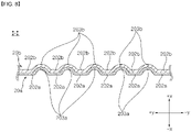
FIG. 8 is a view showing a cross-section of the header panel taken along line I-I' ofFIG. 7 . -
FIG. 9 is a view showing a structure in which a header panel module is inserted in a header case. -
FIG. 10 is a view showing a structure in which a cap block is inserted in a header case. -
FIG. 11 is a block diagram showing a method of manufacturing a heat exchanger according to an embodiment of the present disclosure. - The advantages and features of the present disclosure, and methods of achieving them will be clear by referring to the exemplary embodiments that will be described hereafter in detail with reference to the accompanying drawings. However, the present disclosure is not limited to the exemplary embodiments described hereafter and may be implemented in various ways, and the exemplary embodiments are provided to complete the description of the present disclosure and let those skilled in the art completely know the scope of the present disclosure and the present disclosure is defined by claims. Like reference numerals indicate like components throughout the specification.
- Spatial relative terms "below", "beneath", "lower", "above", "upper", etc. may be used to easily describe the correlation of one component and another component, as shown in the drawings. The spatially relative terms should be construed as terminologies including different directions of components in using or in operating in addition to the directions shown in drawings. For example, when components shown in the drawings are turned upside down, a component described as being "below" or "beneath" another component may be positioned "over" the another component. Accordingly, "below" and "beneath" that are exemplary terms may include both of up and down directions. A component may be oriented in different directions, so the spatially relative terms may be construed in accordance with orientation.
- The terms used herein are provided to describe embodiments without limiting the present disclosure. In the specification, a singular form includes a plural form unless specifically stated in the sentences. The terms "comprise" and/or "comprising" used herein do not exclude that another component, step, and/or operation exist or are added in the stated component, step, and/or operation.
- Unless defined otherwise, all terms (including technological and scientific terminologies) used herein may be used as meanings that those skilled in the art can commonly understand. Terms defined in common dictionaries are not construed ideally or excessively unless specifically clearly defined.
- The thickness or size of components is exaggerated, omitted, or schematically shown in the drawings for convenience and clarity of description. The size or area of components does not generally reflect the actual size or area.
- Hereinafter, the present disclosure will be described with reference to the drawings illustrating a heat exchanger according to exemplary embodiments of the present disclosure.
- Hereafter, directions are defined for a heat exchanger according to an embodiment of the present disclosure and components thereof on the basis of the coordinate system shown in
FIGS. 1 to 11 . - The directions in which the x-axis extends may be defined as up and down directions. The direction in which the +x-axis extends from the origin may be the up direction and the direction in which the -x-axis extends from the origin may be the down direction. The directions in which the y-axis extends may be defined as front and rear directions. The direction in which the +y-axis extends from the origin may be the front direction and the direction in which the -y-axis extends from the origin may be the rear direction. The directions in which the z-axis extends may be defined as left and right directions. The direction in which the +z-axis extends may be the right direction and the direction in which the -z-axis extends may be the left direction.
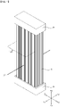
- Referring to
FIG. 1 , a heat exchanger according to the present disclosure may include atube panel 10. Thetube panel 10 may be elongated in one direction. Thetube panel 10 may have a plurality ofchannels 101 therein through which a refrigerant passes (seeFIG. 3 ). - The heat exchanger according to the present disclosure includes a header H. The header H may be provided in a pair and may be coupled to both ends of the
tube panel 10. The header H may be elongated to a side. A plurality oftube panels 10 may be spaced apart from each other and arranged in the longitudinal direction of the header H. The header H may be formed by combining aheader case 30 and a header panel module 200 (seeFIG. 9 ). - A refrigerant can flow into any one of the pair of headers H. The refrigerant flowing inside can pass through the
channels 101 of thetube panel 10. The refrigerant that has passed through thechannels 101 can flow into the other one of the pair of headers H and then can be discharged out of the heat exchanger. Air can exchange heat with the refrigerant while passing through between a plurality oftube panels 10. - Referring to
FIGS. 2 and3 , according to an embodiment of the present disclosure, thetube panel 10 may be elongated in the up-down direction.Header panels 10 may be formed in a pair at the upper end and lower end of thetube panel 10, respectively. Theheader panels 20 may be elongated in the left-right direction. Theheader panels 20 may be disposed perpendicular to thetube panel 10. - The
tube panel 10 may be formed by bonding afirst panel 11 and asecond panel 12 to each other. Thefirst panel 11 may be composed of a plurality of flat portions and a plurality of recessions that is convex on a side. Thesecond panel 12, similar to the first panel, may be composed of a plurality of flat portions and a plurality of recessions that is convex on another side. The flat portions and the recessions may be elongated in the up-down direction. - The
first panel 11 and thesecond panel 12 may have the same shape. Thefirst panel 11 and thesecond panel 12 may have the same shape and may be turned over 180 degrees and bonded to each other. - A plurality of
fins 102 andtubes 102 may be formed by bonding thefirst panel 11 and thesecond panel 12 to each other. Thefins 102 may be formed by bonding the flat portions of thefirst panel 11 and the flat portions of thesecond panel 12. The plurality of tubes may be formed by disposing the recessions of thefirst panel 11 and the recessions of thesecond panel 12 to be convex in opposite directions.Channels 101 may be formed in thetubes 102. - The
header panels 20 may be formed by bending both ends of thetube panel 10. Theheader panels 20 may be formed by bending both ends of thefirst panel 11 and thesecond panel 12 in opposite directions. Thefirst panel 11 and thesecond panel 12 may be bent perpendicular to thetube panel 10. Theheader panels 20 each may be divided into aheader panel portion 21 formed by bending an end of thefirst panel 11 and aheader panel portion 22 formed by bending an end of thesecond panel 12. - The
first panel 11 and thesecond panel 12 may be made of metal such as stainless steel, copper, and aluminum. Theheader panel 20 may be formed by inserting a jig between both ends of thefirst panel 11 and thesecond panel 12 and then opening the ends to both sides. The properties of thefirst panel 11 and thesecond panel 12 may be adjusted through heat treatment before thefirst panel 11 and thesecond panel 12 are opened by a jig. - When the
header panels 20 are formed, thechannels 101 of thetube panel 10 are formed through theheader panels 20 and may be exposed to the outside of thetube panel 10. - The
header panels 20 are formed by bending both ends of thefirst panel 11 and thesecond panel 12, whereby they may have a plurality offlat portions 202 andrecessions 203 alternately arranged. - A tube panel 10' according to another embodiment of the present disclosure is described hereafter with reference to
FIGS. 4 to 6 mainly about differences from thetube panel 10 according to an embodiment of the present disclosure described with reference toFIGS. 2 and3 , and the same configuration is not described. - Both ends of the tube panel 10' according to an embodiment of the present disclosure may be formed flat. Both ends of the tube panel 10' may be formed by flattening after heat treatment. Both ends of the tube panel 10' may be formed by bonding a first panel 11' and a second panel 12' of which both ends are flat.
- Header panels 20' may be formed by bending both ends of the tube panel 10'. The header panels 20' may be formed by bending both ends of the first panel 11' and the second panel 12' in opposite directions. The first panel 11' and the second panel 12' may be bent perpendicular to the tube panel 10'.
- The first panel 11' and the second panel 12' may be made of metal such as stainless steel, copper, and aluminum. The header panel 20' may be formed by inserting a jig between both ends of the first panel 11' and the second panel 12' and then opening the ends to both sides. The properties of the first panel 11' and the second panel 12' may be adjusted through heat treatment before the first panel 11' and the second panel 12' are opened by a jig.
- The header panels 20' may be formed flat. When the header panels 20' are formed by bending the first panel 11' and the second panel 12', channels 101' formed at the
tube panel 10 may not be exposed to the outside by the header panels 20' (seeFIG.5 ). The channels 101' may be exposed to the outside of the tube panel 10' by punching the header panel 20' (seeFIG. 6 ). - Referring to
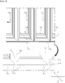
FIG. 7 , thetube panel 10 may be divided into afirst tube panel 10a and asecond tube panel 10b that are elongated in the up-down direction. Thefirst tube panel 10a and thesecond tube panel 10b each may be provided as one or more pieces. Thefirst tube panel 10a and thesecond tube panel 10b may be alternately arranged. Thefirst tube panel 10a and thesecond tube panel 10b may be disposed in parallel with each other. Thefirst tube panel 10a and/or thesecond tube panel 10b may be the same as thetube panels 10 and 10' described above. Thefirst tube panel 10a and thesecond tube panel 10b may have the same shape. - The
first tube panel 10a may be formed by bonding afirst panel 11a and asecond panel 12a. Thesecond tube panel 10b may be formed by bonding athird panel 11b and afourth panel 12b. Thefirst panel 11a and thesecond panel 12a are the same as thefirst panel 11 and thesecond panel 12 described above, so they are not described. Thethird panel 11b and thefourth panel 12b are the same as thefirst panel 11 and thesecond panel 12 described above, so they are not described. - The
header panels 20 may be divided intofirst header panels 20a formed at both ends of thefirst tube panel 10a andsecond header panels 20b formed at both ends of thesecond tube panel 10b. Thefirst header panels 20a may be formed by bending both ends of thefirst panel 11a and thesecond panel 12a in opposite directions. Thesecond header panel 20b may be formed by bending both ends of thethird panel 11b and thefourth panel 12b in opposite directions. Thefirst header panel 20a and thesecond header panel 20b may have the same shape. - The
first header panel 20a and thesecond header panel 20b may be overlapped and bonded to each other. Thefirst header panel 20a and thesecond header panel 20b may be overlapped and bonded between everyfirst tube panel 10a andsecond tube panel 10. - A plurality of
first tube panels 10a may be spaced apart from each other in parallel with each other. A plurality offirst header panels 20a formed at the plurality offirst tube panels 10a may be disposed in the same plane. The plurality offirst header panels 20a may be spaced apart from each other. - A plurality of
first tube panels 10a may be spaced apart from each other in parallel with each other. A plurality ofsecond header panels 20b may be disposed in the same plane. The plurality ofsecond header panels 20b may be spaced apart from each other. Thefirst header panels 20a and thesecond header panels 20b may be formed in parallel with each other. - The
first tube panel 10a and thesecond tube panel 10b may be alternately arranged and may be disposed in parallel to face each other. Thesecond header panel 20b may be bonded to the top of thefirst header panel 20a. Thefirst header panel 20a and thesecond header panel 20b may be alternately disposed and may overlap each other between thefirst tube panel 10a and thesecond tube panel 10. - The
first header panel 20a may be spaced apart from the channels 101 (FIG. 3 ) formed in thesecond tube panel 10b. That is, thechannels 101 may be exposed to the outside without being covered by thefirst header panel 201. - The other
first header panels 20a except for the outermostfirst header panel 20a of the plurality offirst header panels 20a may be bonded to twosecond header panels 20b. The othersecond header panels 20b except for the outermostsecond header panel 20b of the plurality ofsecond header panels 20b may be bonded to twofirst header panels 20a. - Although only the
tube panel 10 and theheader panel 20 according to an embodiment of the present disclosure were described above, the configuration may also be applied to the tube panel 10' and the header panel 20' according to another embodiment of the present disclosure. - Referring to
FIG. 8 , thefirst header panel 20a according to an embodiment of the present disclosure may have a plurality offlat portions 202a andfirst recessions 203a convexly formed from the firstflat portions 202a. The firstflat portions 202 and thefirst recessions 203a may be alternately arranged. Thesecond header panel 20b according to an embodiment of the present disclosure may have a plurality of secondflat portions 202b andsecond recessions 203b convexly formed from the secondflat portions 202b. The secondflat portions 202b and thesecond recessions 203b may be alternately arranged. - The first
flat portion 202a and the secondflat portion 202b may be bonded to each other at the portion where thefirst header panel 20a and thesecond header panel 20b are bonded. Thefirst recession 203a and the second recession 230b may be in contact with each other at the portion where thefirst header panel 20a and thesecond header panel 20b are bonded. - The second
flat portion 202b may be bonded to the top of the firstflat portion 202a. Thesecond recession 203b may be bonded to the top of thefirst recession 203a. Thefirst recession 203a may be inserted under thesecond recession 203b. - Referring to
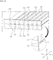
FIG. 9 , aheader case 30 may be open on a one side and may provide aspace 31 therein. Theheader case 30 may be closed on an other side. The front-rear direction and left-right direction of thespace 31 may be surrounded by thefront surface 34, therear surface 33, and bothsides 32 of theheader case 30. The bothsides 32 may be a left side formed at the left of theheader case 30 and a right side formed at the right of theheader case 30. - A refrigerant may flow into the
header case 30 or may be discharged from theheader case 30. The heat exchanger may include a pair ofheader cases 30. A refrigerant flowing in any one of the pair ofheader cases 30 may be discharged outside through the other one of the pair ofheader cases 30. - A
tube panel module 100 may be composed of a plurality oftube panels 10 disposed in parallel. Thetube panel module 100 may include a plurality offirst tube panels 10a andsecond tube panels 10b. - A
header panel module 200 may be formed at the upper end and the lower end of thetube panel module 100. Theheader panel module 200 may be elongated in the left-right direction. Theheader panel module 200 may be disposed perpendicular to thetube panel module 100. - The
header panel module 200 may be composed of a plurality ofheader panels 20 overlapping each other. Theheader panel module 200 may include afirst header panel 20a and asecond header panel 20b. - The
header panel module 200 is inserted in one side of theheader case 200, thereby being able to cover the open one side of theheader case 30. When theheader panel module 200 covers the one side of theheader case 200, thechannels 101 formed in thetube panels 10 can communicate with thespace 31 of theheader case 30. - The portions positioned at the left end and the right end of the
header panel module 200 and protruding left and right from thetube panel module 100 may be defined asinsertion panels 201. Theinsertion panels 201, which are a part of theheader panel 20, may be portions that do not overlappingother header panel 20. - A
first insertion groove 321 may be formed on bothsides 32 of theheader case 30. That is, thefirst insertion groove 321 may be formed on theleft side 32 and theright side 32 of theheader case 30. Thefirst insertion grooves 32 may be recessed on bothsides 32 of theheader case 30 to face thespace 31 of theheader case 30. Thefirst insertion grooves 32 may have a shape elongated in the front-rear direction. - The
insertion panels 201 may be inserted and coupled in thefirst insertion grooves 321. When theinsertion panels 201 are inserted in thefirst insertion grooves 321, theheader panel module 200 can cover the open one side of thecase 30. - Referring to
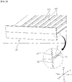
FIG. 10 , thefirst insertion grooves 321 may be elongated rearward from the front end of theheader case 30. Thefirst insertion grooves 321 can guide insertion of theinsertion panels 201. Theinsertion panels 201 can be inserted into the front ends of thefirst insertion grooves 321 and then guided rearward along thefirst insertion grooves 321. - The
front surface 34 of theheader case 30 may be formed lower than the height of thefirst insertion grooves 321. Accordingly, when theinsertion panels 201 are inserted into the front ends of thefirst insertion grooves 321 and then guided rearward, theheader panel module 200 can move over the top of thefront surface 34. - The
header case 30 may include acap block 342 disposed on thefront surface 34 of the header case. Thecap block 342 may face thespace 31 of theheader case 30. Thecap block 342 may be positioned in the same plane as thefront surface 34 of theheader case 30. Thecap block 342 can cover the front of theheader case 30 in cooperation with thefront surface 34. - The
cap block 342 may be inserted in the front ends of thefirst insertion grooves 321. After theinsertion panels 201 are inserted in thefirst insertion grooves 321, thecap block 342 may be inserted into the front ends of thefirst insertion grooves 321. Thecap block 342 may come in contact with theheader module panel 200 inserted in thefirst insertion grooves 321 and thefront surface 34 of the header case. - The
cap block 342 may haveprotrusions 341 having a shape corresponding to thefirst insertion groove 321. Theprotrusions 341 may be formed in a pair at both sides of thecap block 342 and inserted in thefirst insertion grooves 321. - Referring to
FIGS. 9 and10 , asecond insertion groove 331 may be formed on therear surface 33 of theheader case 30. Thesecond insertion groove 331 may be recessed on therear surface 33 of theheader case 30 to face thespace 31. Theheader panel module 200 may be inserted in thesecond insertion groove 331. A portion of thetube panel module 100 that is adjacent to theheader panel module 200 may be inserted in thesecond insertion groove 331. - The
second insertion groove 331 may include a plurality oftube panel grooves 331a andheader panel grooves 331b. Thetube panel grooves 331a may have a shape corresponding to thetube panel 10. Thetube panel grooves 331a may be elongated in the up-down direction. Thetube panel grooves 331a may be formed in the same number as thetube panels 10 and may be arranged in the left-right direction. The plurality oftube panels 10 may be inserted in the plurality oftube panel grooves 331a. - The
header panel grooves 331b may have a shape corresponding to theheader panel module 200. Theheader panel grooves 331b may be elongated in the left-right direction. Theheader panel module 200 may be inserted in theheader panel grooves 331b. The plurality oftube panel grooves 331a andheader panel grooves 331b may be continuously formed. - The
second insertion groove 331 may be formed in a pair on the rear and front of theheader case 30. For example, thesecond insertion groove 331 may be formed on thefront surface 34 of theheader case 30. Thesecond insertion groove 331 may be recessed on the inner side of thefront surface 34 to face thespace 31. Alternatively, thesecond insertion groove 331 may be formed at thecap block 342. Thesecond insertion groove 331 may be recessed on thecap block 342 to face thespace 31. - Referring to
FIG. 11 , a method of manufacturing a heat exchanger according to an embodiment of the present disclosure may include a step X1 of forming atube panel 10. In the step X1, thetube panel 10 may be formed by bonding a pair of panels. - For example, as described above, the
first tube panel 10a may be formed by bonding afirst panel 11a and asecond panel 12a. Thesecond tube panel 10b may be formed by bonding athird panel 11b and thesecond panel 12b. - The method of manufacturing a heat exchanger may include a step X2 of forming a
header panel 20. In the step X2, theheader panel 20 may be formed by bending both ends of thetube panel 10. - For example, the
first header panel 20a may be formed by bending both ends of thefirst panel 11a and thesecond panel 12a of thefirst tube panel 10a in opposite directions. Thesecond header panel 20b may be formed by bending both ends of thethird panel 11b and thefourth panel 12b of thesecond tube panel 10b in opposite directions. - The
first header panel 20a may be formed by inserting a jig between both ends of thefirst panel 11a and thesecond panel 12a and then opening the ends to both sides. Thesecond header panel 20b may be formed by inserting a jig between both ends of thethird panel 11b and thefourth panel 12b and then opening the ends to both sides. Properties of both ends of the panels may be adjusted through heat treatment before the panels are opened by a jig. - The step X2 may further include a step of making both ends of the
tube panel 10 flat through flattening after heat treatment. In this case, a step of exposingchannels 101 to the outside of thetube panel 10 by punching theheader panel 20 at positions corresponding to thechannels 101 after forming theheader panel 20 may be further included. - The method of manufacturing a heat exchanger may include a step X3 of overlapping a plurality of
header panels 20. - In the step X3, the plurality of
tube panels 10 may be arranged, and a plurality offirst tube panels 10a and a plurality ofsecond tube panels 10b may be arranged in parallel to face each other. The plurality offirst tube panels 10a and the plurality ofsecond tube panels 10b may be alternately arranged. - The
second header panel 20b may be brought in contact with thefirst header panel 20b. Thesecond header panel 20b and thefirst header panel 20a may be in contact with each other between the first andsecond tube panels second header panel 20b may be disposed on thefirst header panel 20a. - A component formed by combining the plurality of
tube panels 10 may be referred to as atube panel module 100. A component formed by combining the plurality of overlappingheader panels 20 may be referred to as aheader panel module 200. - The method of manufacturing a heat exchanger may include a step X4 of inserting the
header panel module 200 in aheader case 30. Theheader panel module 200 can cover an open one side of theheader case 30 by being inserted in theheader case 30. This was described above, so it is not described here. - The method of manufacturing a heat exchanger may include a brazing step X5. In the step X5, the contact portions between the plurality of
header panels 20 and theheader case 30 may be brazed. - In a step before the brazing step X5, a filter material may be applied to all of the portions where the components of the heat exchanger are in contact with each other. In the step X5, it is possible to bond the components in a brazing type by selectively melting only the filler material by applying high-temperature heat to the heat exchanger and then cooling it. The heat exchanger may be put and brazed in a high-temperature furnace.
- The steps X1 to X5 may be sequentially performed.
Claims (14)
- A heat exchanger comprising:a tube panel module elongated in an up-down direction and including a plurality of first tube panels and second tube panels that are alternately arranged in a left-right direction;header panel modules respectively formed at an upper end and a lower end of the tube panel module and elongated in a left-right direction; anda header case having an open one side, providing a space therein, and covered on the one side by the cover module such that the first tube panels and the second tube panels communicate with the space,wherein the first tube panel is formed by bonding a first panel and a second panel,the second tube panel is formed by bonding a third panel and a fourth panel, andthe header panel module includes:a first header panel formed by bending both ends of the first panel and the second panel in opposite directions; anda second header panel formed by bending both ends of the third panel and the fourth panel in opposite directions and bonded to the first header panel between every first tube panel and second tube panel.
- The heat exchanger of claim 1, wherein the first header panel is disposed perpendicular to the first tube panel, and
the second header panel is disposed perpendicular to the second tube panel. - The heat exchanger of claim 1, or 2, wherein the first header panel has first flat portions and first recessions that are alternately formed,the second header panel has second flat portions and second recessions that are alternately formed, andthe first flat portion and the second flat portion are in contact with each other, and the first recession and the second recession are in contact with each other at a portion where the first header panel and the second header panel are bonded.
- The heat exchanger of claim 1, 2, or 3, wherein the first header panel is formed by bending both ends of the first panel and the second panel that are flat, and
the second header panel is formed by bending both ends of the third panel and the fourth panel that are flat. - The heat exchanger of claim 4, wherein the first tube panel and the second tube panel each have a channel through which a refrigerant flows, and
the channels are exposed to the outside of the first tube panel and the second tube panel by punching the first header panel and the second header panel. - The heat exchanger of any one of claims 1 to 5, wherein the first header panel is formed by inserting a jig between both ends of the first panel and the second panel and then opening the ends to both sides, and
the second header panel is formed by inserting a jig between both ends of the third panel and the fourth panel and then opening the ends to both sides. - The heat exchanger of any one of claims 1 to 6, wherein the plurality of first header panels are disposed in the same plane, and
the plurality of second header panels are disposed in the same plane and bonded to tops of the first header panels. - The heat exchanger of any one of claims 1 to 7, wherein when portions positioned at a left end and a right end of the header panel module and protruding left and right from the tube panel module are defined as insertion panels,
the header case further includes first insertion grooves that are recessed on a left side and a right side of the header case to face the space and in which the insertion panels are inserted. - The heat exchanger of claim 8, wherein the first insertion grooves are elongated rearward from a front end of the header case and guide insertion of the insertion panels, and
a front surface of the header case is formed lower than a height of the first insertion grooves and the header panel module moves over a top of the front surface. - The heat exchanger of claim 9, wherein the header case includes a cap block inserted in the first insertion grooves and being in contact with the header panel module and the front surface of the header case.
- The heat exchanger of claim 10, wherein a rear surface of the header case and the cap block include a second insertion groove that is recessed to face the space and in which the header panel module and a portion of the tube panel module are inserted.
- The heat exchanger of claim 11, wherein the second insertion groove includes:a plurality of tube panel grooves that are elongated in the up-down direction and are arranged in the left-right direction and in which the plurality of tube panels are inserted; anda header panel groove that is elongated in the left-right direction and in which the header panel module is inserted.
- A method of manufacturing a heat exchanger, the method comprising:forming a plurality of tube panels by bonding a pair of panels;forming a plurality of header panels by bending ends of the plurality of tube panels;forming a header panel module by overlapping the plurality of header panels;inserting the header panel module in an open one side of a header case; andbrazing contact portions between the plurality of header panels and the header case.
- The method of claim 13, wherein the forming of a plurality of header panels bends ends of the pair of panels in opposite directions.
Applications Claiming Priority (1)
| Application Number | Priority Date | Filing Date | Title |
|---|---|---|---|
| KR1020200134404A KR20220050575A (en) | 2020-10-16 | 2020-10-16 | Heat exchanger and heat exchanger manufacturing method |
Publications (1)
| Publication Number | Publication Date |
|---|---|
| EP3985342A1 true EP3985342A1 (en) | 2022-04-20 |
Family
ID=78212037
Family Applications (1)
| Application Number | Title | Priority Date | Filing Date |
|---|---|---|---|
| EP21202822.9A Pending EP3985342A1 (en) | 2020-10-16 | 2021-10-15 | Heat exchanger and heat exchanger manufacturing method |
Country Status (3)
| Country | Link |
|---|---|
| US (1) | US20220120503A1 (en) |
| EP (1) | EP3985342A1 (en) |
| KR (1) | KR20220050575A (en) |
Citations (7)
| Publication number | Priority date | Publication date | Assignee | Title |
|---|---|---|---|---|
| US1950500A (en) * | 1932-04-19 | 1934-03-13 | Loprich | Radiator fin |
| KR100644135B1 (en) | 2005-11-14 | 2006-11-10 | 주식회사 두원공조 | Header pipe of heat exchanger |
| KR200432601Y1 (en) | 2006-07-10 | 2006-12-05 | 주식회사 고산 | Header pipe for heat exchanger |
| US20130146255A1 (en) * | 2011-12-09 | 2013-06-13 | Hyundai Motor Company | Heat exchanger for vehicle |
| KR101447072B1 (en) | 2008-09-08 | 2014-10-06 | 한라비스테온공조 주식회사 | Header assembly of heat exchanger |
| KR20190097632A (en) | 2018-02-12 | 2019-08-21 | 엘지전자 주식회사 | Small diameter tube heat exchanger with reduced air pressure loss |
| EP3598052A1 (en) * | 2017-03-16 | 2020-01-22 | Daikin Industries, Ltd. | Heat exchanger having heat transfer tube unit |
-
2020
- 2020-10-16 KR KR1020200134404A patent/KR20220050575A/en active Search and Examination
-
2021
- 2021-10-14 US US17/501,116 patent/US20220120503A1/en active Pending
- 2021-10-15 EP EP21202822.9A patent/EP3985342A1/en active Pending
Patent Citations (7)
| Publication number | Priority date | Publication date | Assignee | Title |
|---|---|---|---|---|
| US1950500A (en) * | 1932-04-19 | 1934-03-13 | Loprich | Radiator fin |
| KR100644135B1 (en) | 2005-11-14 | 2006-11-10 | 주식회사 두원공조 | Header pipe of heat exchanger |
| KR200432601Y1 (en) | 2006-07-10 | 2006-12-05 | 주식회사 고산 | Header pipe for heat exchanger |
| KR101447072B1 (en) | 2008-09-08 | 2014-10-06 | 한라비스테온공조 주식회사 | Header assembly of heat exchanger |
| US20130146255A1 (en) * | 2011-12-09 | 2013-06-13 | Hyundai Motor Company | Heat exchanger for vehicle |
| EP3598052A1 (en) * | 2017-03-16 | 2020-01-22 | Daikin Industries, Ltd. | Heat exchanger having heat transfer tube unit |
| KR20190097632A (en) | 2018-02-12 | 2019-08-21 | 엘지전자 주식회사 | Small diameter tube heat exchanger with reduced air pressure loss |
Also Published As
| Publication number | Publication date |
|---|---|
| US20220120503A1 (en) | 2022-04-21 |
| KR20220050575A (en) | 2022-04-25 |
Similar Documents
| Publication | Publication Date | Title |
|---|---|---|
| US5625229A (en) | Heat sink fin assembly for cooling an LSI package | |
| US20060168812A1 (en) | Method of forming heat exchanger tubing and tubing formed thereby | |
| EP2884209B1 (en) | Bent heat exchanger and method for bending the heat exchanger | |
| WO2005088225A1 (en) | Heat exchanger header tank and heat exchanger comprising same | |
| GB2466687A (en) | Heat exchanger and method of manufacturing a heat exchanger | |
| EP3124905B1 (en) | Heat exchanger | |
| CN103925826A (en) | Tube for a heat exchanger | |
| US9669455B2 (en) | Method for producing a heat exchanger and heat exchanger obtained by said method, swage and tube expansion device for implementing said method | |
| WO2014041771A1 (en) | Heat exchanger | |
| CN104121800A (en) | Circulating pipe joint and heat exchanger with same | |
| EP2031334B1 (en) | Heat exchanger | |
| CN113939705A (en) | Heat exchanger | |
| EP3985342A1 (en) | Heat exchanger and heat exchanger manufacturing method | |
| WO2019234847A1 (en) | Heat exchanger | |
| JP4448354B2 (en) | Heat exchanger | |
| JP6413760B2 (en) | Heat exchanger and heat exchanger unit using the same | |
| JP6455103B2 (en) | Heat exchanger | |
| US11940219B2 (en) | Heat exchanger and heat exchanger manufacturing method | |
| JP6136124B2 (en) | Heat exchanger manufacturing method and heat exchanger | |
| KR20190096170A (en) | Heat exchanger for refrigerator | |
| JP6614068B2 (en) | Heat exchanger | |
| JP2576197B2 (en) | Heat exchanger | |
| JP2004534930A (en) | Heat exchanger tube bundle with improved exchange surface | |
| EP4130633A1 (en) | Heat exchanger, refrigeration cycle device, and method for manufacturing heat exchanger | |
| CN100368755C (en) | Flat hollow body for passing fluid therethrough, heat exchanger comprising the hollow body and process for fabricating the heat exchanger |
Legal Events
| Date | Code | Title | Description |
|---|---|---|---|
| PUAI | Public reference made under article 153(3) epc to a published international application that has entered the european phase |
Free format text: ORIGINAL CODE: 0009012 |
|
| STAA | Information on the status of an ep patent application or granted ep patent |
Free format text: STATUS: REQUEST FOR EXAMINATION WAS MADE |
|
| 17P | Request for examination filed |
Effective date: 20211015 |
|
| AK | Designated contracting states |
Kind code of ref document: A1 Designated state(s): AL AT BE BG CH CY CZ DE DK EE ES FI FR GB GR HR HU IE IS IT LI LT LU LV MC MK MT NL NO PL PT RO RS SE SI SK SM TR |
|
| RBV | Designated contracting states (corrected) |
Designated state(s): AL AT BE BG CH CY CZ DE DK EE ES FI FR GB GR HR HU IE IS IT LI LT LU LV MC MK MT NL NO PL PT RO RS SE SI SK SM TR |
|
| STAA | Information on the status of an ep patent application or granted ep patent |
Free format text: STATUS: EXAMINATION IS IN PROGRESS |
|
| 17Q | First examination report despatched |
Effective date: 20230503 |
|
| GRAP | Despatch of communication of intention to grant a patent |
Free format text: ORIGINAL CODE: EPIDOSNIGR1 |
|
| STAA | Information on the status of an ep patent application or granted ep patent |
Free format text: STATUS: GRANT OF PATENT IS INTENDED |
|
| INTG | Intention to grant announced |
Effective date: 20240124 |