EP3985302A1 - Verstellbarer träger zur befestigung einer beleuchtungeinrichtung einer strassenleuchte und strassenleuchte - Google Patents
Verstellbarer träger zur befestigung einer beleuchtungeinrichtung einer strassenleuchte und strassenleuchte Download PDFInfo
- Publication number
- EP3985302A1 EP3985302A1 EP20201730.7A EP20201730A EP3985302A1 EP 3985302 A1 EP3985302 A1 EP 3985302A1 EP 20201730 A EP20201730 A EP 20201730A EP 3985302 A1 EP3985302 A1 EP 3985302A1
- Authority
- EP
- European Patent Office
- Prior art keywords
- fitting
- bushing
- relative
- light
- auxiliary
- Prior art date
- Legal status (The legal status is an assumption and is not a legal conclusion. Google has not performed a legal analysis and makes no representation as to the accuracy of the status listed.)
- Withdrawn
Links
Images


Classifications
-
- F—MECHANICAL ENGINEERING; LIGHTING; HEATING; WEAPONS; BLASTING
- F21—LIGHTING
- F21S—NON-PORTABLE LIGHTING DEVICES; SYSTEMS THEREOF; VEHICLE LIGHTING DEVICES SPECIALLY ADAPTED FOR VEHICLE EXTERIORS
- F21S8/00—Lighting devices intended for fixed installation
- F21S8/08—Lighting devices intended for fixed installation with a standard
- F21S8/085—Lighting devices intended for fixed installation with a standard of high-built type, e.g. street light
- F21S8/086—Lighting devices intended for fixed installation with a standard of high-built type, e.g. street light with lighting device attached sideways of the standard, e.g. for roads and highways
-
- F—MECHANICAL ENGINEERING; LIGHTING; HEATING; WEAPONS; BLASTING
- F21—LIGHTING
- F21V—FUNCTIONAL FEATURES OR DETAILS OF LIGHTING DEVICES OR SYSTEMS THEREOF; STRUCTURAL COMBINATIONS OF LIGHTING DEVICES WITH OTHER ARTICLES, NOT OTHERWISE PROVIDED FOR
- F21V19/00—Fastening of light sources or lamp holders
- F21V19/02—Fastening of light sources or lamp holders with provision for adjustment, e.g. for focusing
-
- F—MECHANICAL ENGINEERING; LIGHTING; HEATING; WEAPONS; BLASTING
- F21—LIGHTING
- F21V—FUNCTIONAL FEATURES OR DETAILS OF LIGHTING DEVICES OR SYSTEMS THEREOF; STRUCTURAL COMBINATIONS OF LIGHTING DEVICES WITH OTHER ARTICLES, NOT OTHERWISE PROVIDED FOR
- F21V21/00—Supporting, suspending, or attaching arrangements for lighting devices; Hand grips
- F21V21/10—Pendants, arms, or standards; Fixing lighting devices to pendants, arms, or standards
- F21V21/116—Fixing lighting devices to arms or standards
-
- F—MECHANICAL ENGINEERING; LIGHTING; HEATING; WEAPONS; BLASTING
- F21—LIGHTING
- F21V—FUNCTIONAL FEATURES OR DETAILS OF LIGHTING DEVICES OR SYSTEMS THEREOF; STRUCTURAL COMBINATIONS OF LIGHTING DEVICES WITH OTHER ARTICLES, NOT OTHERWISE PROVIDED FOR
- F21V21/00—Supporting, suspending, or attaching arrangements for lighting devices; Hand grips
- F21V21/14—Adjustable mountings
- F21V21/30—Pivoted housings or frames
-
- F—MECHANICAL ENGINEERING; LIGHTING; HEATING; WEAPONS; BLASTING
- F21—LIGHTING
- F21W—INDEXING SCHEME ASSOCIATED WITH SUBCLASSES F21K, F21L, F21S and F21V, RELATING TO USES OR APPLICATIONS OF LIGHTING DEVICES OR SYSTEMS
- F21W2131/00—Use or application of lighting devices or systems not provided for in codes F21W2102/00-F21W2121/00
- F21W2131/10—Outdoor lighting
- F21W2131/103—Outdoor lighting of streets or roads
Definitions
- the object of the invention is an adjustable handle for mounting the light fitting of a road lamp, in particular a LED light.
- the object of the invention is also a road lamp, in particular a LED light.
- Street (road) lights are mounted along communication routes (streets, roads, crossroads, etc.) in order to illuminate them and areas adjacent to them.
- Road conditions are complex and variable; roads can be curved, go up or down, etc.
- Various levels of light intensity are required depending on the existing conditions.
- Most of conventionally mounted road lamps provide vertical downward illumination and they are not capable of guaranteeing a proper light intensity level, adhering to quality standards.
- Chinese utility model CN209262888U discloses an adjustable corner joint for a street light, comprising a bushing adapted to seating on a mast and a bushing adapted to mounting on a fitting post, both bushings being rotatably connected by means of a two-part slot and a screw connecting both parts of the slot, which at the same time fixes the mutual position of both bushings.
- the presented solution enables changing the angular position of the light fitting only relative to the transverse axis of the light fitting.
- the solution disclosed in this document enables changing the angular position of the light fitting only in a transverse axis relative to the fittings of the light.
- the description according to CN103775990A also discloses a LED road lamp with a high power, comprising a light body, a light post and a connecting assembly with an adjustable angle. Most of the resolutions described above enable adjusting the position of the fitting only relative to the transverse axis of the fitting, which does not allow for precise setting of the lighting geometry that would fulfil the requirements and/or the designs.
- a rotating street light comprising a lighting assembly (a light fitting) connected to a connecting post, consisting of three elements connected in sequence, with rotatable constructions used between them, whose axes of rotation are perpendicular relative to each other.
- the solution according to CN207849216U enables changing the angular position of the light fitting relative to two axes perpendicular to each other.
- the first aspect of the invention is an adjustable handle for mounting the light fitting of a road lamp, comprising a main bushing for mounting the handle on a post or a support of the light, an auxiliary bushing for mounting the handle in or on the fitting, the main bushing and the auxiliary bushing being rotatably connected by means of a screw fixing the angular position of the fitting relative to the longitudinal axis of this screw.
- the handle according to the invention further comprises a system for adjusting the position of the fitting relative to the longitudinal axis of the auxiliary bushing, comprising a slit on the perimeter of the auxiliary bushing, a screw passing therethrough which fixes the angular position of the light fitting relative to the longitudinal axis of the auxiliary bushing, connected to a pressure element inside the auxiliary bushing.
- the adjustable handle according to the invention enables adjusting the position of the light fitting of the light, in particular the LED light, in two perpendicular axes, the adjustment in the axis transverse to the longitudinal axis of the fitting being possible within a range of more than +/-180 0 .
- the solution is characterised by a simple design, as well as easy assembly and handling, which is particularly significant in the case of light fittings mounted at considerable heights relative to the ground.
- the pressure element is slidingly seated within the slit, or it has the form of a ring loosely fitted with the auxiliary bushing.
- These solutions allow such blocking of the pressure element which would prevent its rotational movement, at the same time making it possible to tighten the screw fixing the angular position of the fitting relative to the longitudinal axis of the auxiliary bushing without the use of additional tools immobilising the pressure element. This facilitates the assembly and proper angular orientation of the fitting, also facilitating its subsequent handling (e.g. changing the angular position).
- the ends of the main bushing and of the auxiliary bushing placed next to each other are enclosed by face plates, considerably limiting the access of weather elements into the interior of the fitting and the light post.
- the slit enables rotation of the screw relative to the longitudinal axis of the auxiliary bushing by an angle of +/- 15°.
- the main bushing and/or the auxiliary bushing comprise indicators determining the mutual angular position of the main bushing and of the auxiliary bushing.
- the auxiliary bushing comprises indicators determining the angular position of the road fitting relative to the longitudinal axis of the auxiliary bushing.
- the second aspect of the invention is a road lamp, in particular a LED light, comprising the light fitting and the adjustable handle according to the first aspect of the invention.
- the light fitting of the light comprises at least one fixing spike on its outer surface, adjusted to the placement of a device thereon for determining the position of the fitting relative to the ground surface.
- the use of at least one fixing spike allows placing this device in a predetermined position, which translates into the accuracy of the results of measuring the angular position.
- a recommended solution involves the use of three fixing spikes arranged in a triangle, preferably an isosceles triangle.
- the device mounted on the surface of the light fitting enables precise determination of the geometrical orientation of the light fitting (the angle of inclination relative to the longitudinal and transverse axes) and confirmation of the correct geometrical orientation of the light fitting by the performed measurement.
- the device for determining the position of the light fitting relative to the ground surface is provided with a system for mechanically measuring the geometrical orientation of the light fitting relative to the ground surface.
- a system for mechanically measuring the geometrical orientation of the light fitting relative to the ground surface may have the form of two bubble levels arranged at a right angle.
- the device for determining the position of the light fitting relative to the ground surface is provided with a system for electronically measuring the geometrical orientation of the light fitting relative to the ground surface.
- the device for determining the position of the fitting relative to the ground surface is provided with a module for determining the geographical position.
- a module for determining the geographical position allows determining the geographical position of a specific light fitting.
- the module works based on the GPS and/or GLONAS system.
- a wireless communication module in the device for determining the position of the light fitting relative to the ground surface. This allows wireless transmission of data to an external device with dedicated software, like, e.g. a smartphone.
- the solution according to the invention enables precise determination of the geometrical orientation of the light fitting (the angle of inclination relative to the longitudinal and transverse axes) via fluid adjustment of its angular position in two axes perpendicular to each other.
- the adjustment is very simple and it is performed by loosening one screw (for each axis), fixing the required angular inclinations and tightening this screw.
- Our solution does not require blocking the orientation of the light fitting by two or more screws.
- the solution is simple and easy to apply from a lift (while working at heights - a single screw, a single key size).
- the use of the adjustable handle for the light fitting of a road lamp according to the invention affects the quickness of installation of the light fittings (one method of assembly on a boom or on a post), the easiness of setting the geometry of lighting in two axes (precise angular orientation in the transverse and longitudinal axes) and the aesthetics of the entire fitting - the handle is an optically light design, lacking protruding elements.
- the assembly of light fittings on posts and booms, with a varying angle of orientation of the mounting support (a post, a boom) with the use of the handle according to the invention does not require installing additional technical elements.
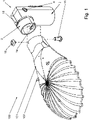
- Figs. 1 - 4 present the adjustable handle 1 for mounting the light fitting of a road lamp, which comprises a main bushing 2 for mounting said handle on a post or a support of the light, an auxiliary bushing 3 for mounting said handle in or on the fitting.
- the main bushing 2 and the auxiliary bushing 3 are rotatably connected via a screw 4 fixing the angular position of the fitting relative to the longitudinal axis of the screw 4.
- the screw 4 is placed in the mutually corresponding protrusions 5, 6 of the main bushing 2 and of the auxiliary bushing 3, which form a positive connection.
- the protrusions 5, 6 have slots 7, 8 intended for a power supply cable for the light fitting.
- the slots 7, 8 have centrally positioned coaxial cylinders 9, 10, in which the screw 4 is placed axially.
- the cylinders 9, 10 constitute an element on which the power supply cable can be loosely wound.
- Winding the cable on the cylinders 9, 10 prevents it from being under tension, which limits the risk of damaging it or ripping it out of the handle.
- the ends of the main bushing 2 and of the auxiliary bushing 3 placed next to each other are enclosed by face plates 11, 12, which considerably limit the access of weather elements into the interior of the fitting and the light post. Openings 13 intended for the power supply cable are made in the face plates 11, 12.
- the adjustable handle 1 further comprises a system for adjusting the position of the light fitting 101 of the road lamp 100 relative to the longitudinal axis of the auxiliary bushing 3.
- This system comprises a slit 14 on the perimeter of the auxiliary bushing 3, a screw 15 passing therethrough which fixes the angular position of the fitting 101 in the longitudinal axis of the auxiliary bushing 3, connected to a pressure element 16 slidingly seated in the slit 14 inside the auxiliary bushing 3.
- the slit 14 is made on a fragment of the perimeter of the auxiliary bushing_3 and it enables the rotation of the screw 15 relative to the longitudinal axis of the auxiliary bushing 3 by an angle of +/- 15°.
- the screw 4 and the screw 15 are mounted by means of the same key (e.g. a hex key).
- main bushing 2 and the auxiliary bushing 3 comprise indicators 17 determining their mutual angular position.
- the auxiliary bushing 3 comprises indicators 18 determining the mutual angular position of the light fitting of the road lamp relative to the longitudinal axis of the auxiliary bushing 3.
- Loosening the screw 4 allows fixing the angular orientation of the main bushing 2 and the auxiliary bushing 3 relative to the longitudinal axis of the screw 4. It is synonymous with setting the mutual angular position of both bushings, as well as setting the angular position of the light fitting relative to a post or a support of the light (e.g. mounted to the wall of a building). Upon fixing the desired position of both bushings, this position is secured by tightening the screw 4.
- the adjustment of the position of the light fitting 101 of the road lamp 100 relative to the longitudinal axis of the auxiliary bushing 3 is in turn performed by loosening the screw 15 placed in the opening of the light fitting 101.
- the pressure element 16 does not press the auxiliary bushing 3 against the element of the light fitting 101, in which or on which the handle 1 is seated. Due to this, the screw 15 can slide freely along the slit 14, which results in the ability to freely and fluidly rotate the fittings relative to the longitudinal axis of the auxiliary bushing 3.
- Fig. 1 and Fig. 5 present the LED road lamp 100 comprising the light fitting 101 and the adjustable handle 1 for mounting the light fitting of the road lamp according to the first embodiment.
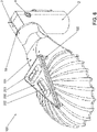
- Figs. 6 and 7 present the LED road lamp 100 like in example 3, the light fitting 101 comprising on its surface three fixing spikes 102, on which there is a device 200 for determining the position of the fitting relative to the ground surface, the device 200 comprising slots 201 adjusted to cooperate with the fixing spikes 102.
- the device 200 is provided with a system for mechanically measuring the geometrical orientation of said light fitting relative to the ground surface in the form of two bubble levels 202, 203 arranged at a right angle.
- the device (200) for determining the position of the fitting (101) relative to the ground surface is also provided with a module for determining the geographical position, the operation of which is based on the GPS and/or GLONAS system.
- the device 200 also comprises a wireless communication module, which allows wireless transmission of data to an external device with dedicated software, like, e.g. a smartphone.
- a wireless communication module which allows wireless transmission of data to an external device with dedicated software, like, e.g. a smartphone.
- the device 200 in combination with dedicated software considerably facilitates correcting the orientation of both new light fittings and those already installed, as well as inventorying the light equipment in possession. This also constitutes a simplification of the installer's equipment - one small device for setting and inventorying.
- the LED road lamp 100 like in example 4, wherein, instead of the system for mechanically measuring the geometrical orientation of said road fitting relative to the ground surface, the light 100 is provided with a system for an electronic measurement of the geometrical orientation.
- this system can have the form of an integrated gyroscopic electronic system known from prior art, comprising a gyroscope and an accelerometer.
Landscapes
- Engineering & Computer Science (AREA)
- General Engineering & Computer Science (AREA)
- Non-Portable Lighting Devices Or Systems Thereof (AREA)
- Road Signs Or Road Markings (AREA)
Priority Applications (1)
| Application Number | Priority Date | Filing Date | Title |
|---|---|---|---|
| EP20201730.7A EP3985302A1 (de) | 2020-10-14 | 2020-10-14 | Verstellbarer träger zur befestigung einer beleuchtungeinrichtung einer strassenleuchte und strassenleuchte |
Applications Claiming Priority (1)
| Application Number | Priority Date | Filing Date | Title |
|---|---|---|---|
| EP20201730.7A EP3985302A1 (de) | 2020-10-14 | 2020-10-14 | Verstellbarer träger zur befestigung einer beleuchtungeinrichtung einer strassenleuchte und strassenleuchte |
Publications (1)
| Publication Number | Publication Date |
|---|---|
| EP3985302A1 true EP3985302A1 (de) | 2022-04-20 |
Family
ID=74556623
Family Applications (1)
| Application Number | Title | Priority Date | Filing Date |
|---|---|---|---|
| EP20201730.7A Withdrawn EP3985302A1 (de) | 2020-10-14 | 2020-10-14 | Verstellbarer träger zur befestigung einer beleuchtungeinrichtung einer strassenleuchte und strassenleuchte |
Country Status (1)
| Country | Link |
|---|---|
| EP (1) | EP3985302A1 (de) |
Citations (11)
| Publication number | Priority date | Publication date | Assignee | Title |
|---|---|---|---|---|
| KR20100052010A (ko) * | 2008-11-10 | 2010-05-19 | (주)대림엘이디라이팅 | 조명기구의 조사각도 조절장치 |
| US20120320589A1 (en) * | 2011-06-15 | 2012-12-20 | Chin-Wen WANG & Ching-Chung WANG | Heat dissipator and led illuminator having heat dissipator |
| CN203202836U (zh) * | 2013-04-29 | 2013-09-18 | 深圳市科纳实业有限公司 | 调节角度的连接组件及带有该连接组件的led路灯 |
| CN103775990A (zh) | 2013-04-29 | 2014-05-07 | 深圳市科纳实业有限公司 | 调节角度的连接组件及带有该连接组件的led路灯 |
| WO2015182588A1 (ja) * | 2014-05-27 | 2015-12-03 | 三菱重工業株式会社 | 照明装置、照明装置調整システム、照明装置調整方法及びプログラム |
| WO2016107863A1 (en) * | 2014-12-30 | 2016-07-07 | Nordgas S.R.L. | Lighting apparatus |
| CN207849216U (zh) | 2018-01-30 | 2018-09-11 | 深圳佳比泰智能照明股份有限公司 | 可旋转路灯 |
| WO2019134899A1 (en) * | 2018-01-05 | 2019-07-11 | Schreder S.A. | System and method for positioning luminaire heads |
| CN209262888U (zh) | 2018-12-03 | 2019-08-16 | 厦门川莆太阳能科技有限公司 | 太阳能路灯转角连接件 |
| CN210107215U (zh) * | 2019-06-25 | 2020-02-21 | 云南天辉光电科技有限公司 | 一种翻转式路灯连接头 |
| NL2022503B1 (en) * | 2019-02-04 | 2020-08-19 | Schreder Sa | Luminaire head inclination level system |
-
2020
- 2020-10-14 EP EP20201730.7A patent/EP3985302A1/de not_active Withdrawn
Patent Citations (11)
| Publication number | Priority date | Publication date | Assignee | Title |
|---|---|---|---|---|
| KR20100052010A (ko) * | 2008-11-10 | 2010-05-19 | (주)대림엘이디라이팅 | 조명기구의 조사각도 조절장치 |
| US20120320589A1 (en) * | 2011-06-15 | 2012-12-20 | Chin-Wen WANG & Ching-Chung WANG | Heat dissipator and led illuminator having heat dissipator |
| CN203202836U (zh) * | 2013-04-29 | 2013-09-18 | 深圳市科纳实业有限公司 | 调节角度的连接组件及带有该连接组件的led路灯 |
| CN103775990A (zh) | 2013-04-29 | 2014-05-07 | 深圳市科纳实业有限公司 | 调节角度的连接组件及带有该连接组件的led路灯 |
| WO2015182588A1 (ja) * | 2014-05-27 | 2015-12-03 | 三菱重工業株式会社 | 照明装置、照明装置調整システム、照明装置調整方法及びプログラム |
| WO2016107863A1 (en) * | 2014-12-30 | 2016-07-07 | Nordgas S.R.L. | Lighting apparatus |
| WO2019134899A1 (en) * | 2018-01-05 | 2019-07-11 | Schreder S.A. | System and method for positioning luminaire heads |
| CN207849216U (zh) | 2018-01-30 | 2018-09-11 | 深圳佳比泰智能照明股份有限公司 | 可旋转路灯 |
| CN209262888U (zh) | 2018-12-03 | 2019-08-16 | 厦门川莆太阳能科技有限公司 | 太阳能路灯转角连接件 |
| NL2022503B1 (en) * | 2019-02-04 | 2020-08-19 | Schreder Sa | Luminaire head inclination level system |
| CN210107215U (zh) * | 2019-06-25 | 2020-02-21 | 云南天辉光电科技有限公司 | 一种翻转式路灯连接头 |
Similar Documents
| Publication | Publication Date | Title |
|---|---|---|
| EP1780688B1 (de) | Montagesystem und Verfahren zum Besfestigen von mindestens einem Element an einem Pfosten | |
| US8104925B2 (en) | Method, apparatus, and system of aiming fixtures or devices | |
| US7918586B2 (en) | Method, apparatus, and system of aiming lighting fixtures | |
| KR101979590B1 (ko) | 높이조절이 가능한 가로등용 지주 | |
| CN210319554U (zh) | 一种建筑工程用照明灯 | |
| US8740423B1 (en) | Unit for use in placing and orienting ground light supporting stake elements | |
| EP3985302A1 (de) | Verstellbarer träger zur befestigung einer beleuchtungeinrichtung einer strassenleuchte und strassenleuchte | |
| US11493193B2 (en) | Attachment device for aircraft landing guidance flashing light and aircraft landing guidance flashing device | |
| US3967381A (en) | Ground slope indicating instrument | |
| CN214530345U (zh) | 一种市政桥梁用安全限高装置 | |
| CN210899764U (zh) | 一种路灯控制系统 | |
| KR20080048771A (ko) | 레이저 수평 수직장치용 삼발이 | |
| CN110730532A (zh) | 一种路灯控制系统 | |
| JP2992442B2 (ja) | 境界杭の埋設補助器具 | |
| CN206234709U (zh) | 一种可调节转动角度的路灯 | |
| KR100625091B1 (ko) | 공동주택용 신호등 지주 수평각도 조절장치 | |
| KR200392252Y1 (ko) | 각도 조절이 가능한 가로등 램프 하우징 | |
| KR20160033889A (ko) | 가로등 | |
| CN214167218U (zh) | 一种市政照明工程用安装平台 | |
| CN211232645U (zh) | 一种可弯曲路灯 | |
| JPS6336289Y2 (de) | ||
| CN219956926U (zh) | 压路机视野测试装置 | |
| CN213394953U (zh) | 一种灯具吊装结构 | |
| CN210051338U (zh) | 一种地下工程用测量装置照明系统 | |
| KR20080048979A (ko) | 레이저 수평 수직장치 |
Legal Events
| Date | Code | Title | Description |
|---|---|---|---|
| PUAI | Public reference made under article 153(3) epc to a published international application that has entered the european phase |
Free format text: ORIGINAL CODE: 0009012 |
|
| STAA | Information on the status of an ep patent application or granted ep patent |
Free format text: STATUS: THE APPLICATION HAS BEEN PUBLISHED |
|
| AK | Designated contracting states |
Kind code of ref document: A1 Designated state(s): AL AT BE BG CH CY CZ DE DK EE ES FI FR GB GR HR HU IE IS IT LI LT LU LV MC MK MT NL NO PL PT RO RS SE SI SK SM TR |
|
| STAA | Information on the status of an ep patent application or granted ep patent |
Free format text: STATUS: THE APPLICATION IS DEEMED TO BE WITHDRAWN |
|
| 18D | Application deemed to be withdrawn |
Effective date: 20221021 |