EP3985234A1 - Blow-by gas recirculating device - Google Patents
Blow-by gas recirculating device Download PDFInfo
- Publication number
- EP3985234A1 EP3985234A1 EP20822942.7A EP20822942A EP3985234A1 EP 3985234 A1 EP3985234 A1 EP 3985234A1 EP 20822942 A EP20822942 A EP 20822942A EP 3985234 A1 EP3985234 A1 EP 3985234A1
- Authority
- EP
- European Patent Office
- Prior art keywords
- blow
- gas
- oil
- head cover
- separator
- Prior art date
- Legal status (The legal status is an assumption and is not a legal conclusion. Google has not performed a legal analysis and makes no representation as to the accuracy of the status listed.)
- Granted
Links
Images





Classifications
-
- F—MECHANICAL ENGINEERING; LIGHTING; HEATING; WEAPONS; BLASTING
- F01—MACHINES OR ENGINES IN GENERAL; ENGINE PLANTS IN GENERAL; STEAM ENGINES
- F01M—LUBRICATING OF MACHINES OR ENGINES IN GENERAL; LUBRICATING INTERNAL COMBUSTION ENGINES; CRANKCASE VENTILATING
- F01M13/00—Crankcase ventilating or breathing
- F01M13/04—Crankcase ventilating or breathing having means for purifying air before leaving crankcase, e.g. removing oil
- F01M13/0416—Crankcase ventilating or breathing having means for purifying air before leaving crankcase, e.g. removing oil arranged in valve-covers
-
- F—MECHANICAL ENGINEERING; LIGHTING; HEATING; WEAPONS; BLASTING
- F01—MACHINES OR ENGINES IN GENERAL; ENGINE PLANTS IN GENERAL; STEAM ENGINES
- F01M—LUBRICATING OF MACHINES OR ENGINES IN GENERAL; LUBRICATING INTERNAL COMBUSTION ENGINES; CRANKCASE VENTILATING
- F01M13/00—Crankcase ventilating or breathing
- F01M13/0011—Breather valves
-
- F—MECHANICAL ENGINEERING; LIGHTING; HEATING; WEAPONS; BLASTING
- F01—MACHINES OR ENGINES IN GENERAL; ENGINE PLANTS IN GENERAL; STEAM ENGINES
- F01M—LUBRICATING OF MACHINES OR ENGINES IN GENERAL; LUBRICATING INTERNAL COMBUSTION ENGINES; CRANKCASE VENTILATING
- F01M13/00—Crankcase ventilating or breathing
- F01M13/04—Crankcase ventilating or breathing having means for purifying air before leaving crankcase, e.g. removing oil
- F01M2013/0433—Crankcase ventilating or breathing having means for purifying air before leaving crankcase, e.g. removing oil with a deflection device, e.g. screen
-
- F—MECHANICAL ENGINEERING; LIGHTING; HEATING; WEAPONS; BLASTING
- F01—MACHINES OR ENGINES IN GENERAL; ENGINE PLANTS IN GENERAL; STEAM ENGINES
- F01M—LUBRICATING OF MACHINES OR ENGINES IN GENERAL; LUBRICATING INTERNAL COMBUSTION ENGINES; CRANKCASE VENTILATING
- F01M13/00—Crankcase ventilating or breathing
- F01M13/04—Crankcase ventilating or breathing having means for purifying air before leaving crankcase, e.g. removing oil
- F01M2013/0438—Crankcase ventilating or breathing having means for purifying air before leaving crankcase, e.g. removing oil with a filter
-
- F—MECHANICAL ENGINEERING; LIGHTING; HEATING; WEAPONS; BLASTING
- F01—MACHINES OR ENGINES IN GENERAL; ENGINE PLANTS IN GENERAL; STEAM ENGINES
- F01M—LUBRICATING OF MACHINES OR ENGINES IN GENERAL; LUBRICATING INTERNAL COMBUSTION ENGINES; CRANKCASE VENTILATING
- F01M13/00—Crankcase ventilating or breathing
- F01M13/04—Crankcase ventilating or breathing having means for purifying air before leaving crankcase, e.g. removing oil
- F01M2013/0472—Crankcase ventilating or breathing having means for purifying air before leaving crankcase, e.g. removing oil using heating means
-
- F—MECHANICAL ENGINEERING; LIGHTING; HEATING; WEAPONS; BLASTING
- F01—MACHINES OR ENGINES IN GENERAL; ENGINE PLANTS IN GENERAL; STEAM ENGINES
- F01M—LUBRICATING OF MACHINES OR ENGINES IN GENERAL; LUBRICATING INTERNAL COMBUSTION ENGINES; CRANKCASE VENTILATING
- F01M13/00—Crankcase ventilating or breathing
- F01M13/04—Crankcase ventilating or breathing having means for purifying air before leaving crankcase, e.g. removing oil
- F01M2013/0488—Crankcase ventilating or breathing having means for purifying air before leaving crankcase, e.g. removing oil with oil trap in the return conduit to the crankcase
- F01M2013/0494—Crankcase ventilating or breathing having means for purifying air before leaving crankcase, e.g. removing oil with oil trap in the return conduit to the crankcase using check valves
Definitions
- the present invention relates to a blow-by gas recirculation device to be mounted on: an industrial engine to be used in an agricultural machine or a construction machine; an automobile engine; or the like.
- blow-by gas recirculation device configured to allow blow-by gas to pass through the inside of a cylinder head cover (hereinafter, abbreviated as a head cover) and then return to an intake path.
- a gas passage is generally provided on the upper side of a valve mechanism in the head cover. Since the gas passage inside the head cover tends to be a flat passage that is vertically narrow, an oil separator for trapping oil components from the blow-by gas is generally provided outside the head cover as a dedicated part (e.g., Patent Document 1).
- the oil separator In the structure in which the oil separator is disposed on the side of a cylinder block, there is almost no limitation on space as inside the head cover, so that there is an advantage that the oil separator can have a sufficient capacity.
- the oil separator which is a dedicated part, is added as an auxiliary machine of the engine, so that there arise the following problems.
- the size (bulk) of the entire engine tends to increase as much as the oil separator is attached.
- the gas passage from the head cover to the intake passage that is, an external pipe becomes large in length, the risk that the moisture contained in the blow-by gas may freeze in cold weather increases.
- Patent Document 1 Japanese Patent Application Laid-open No. 2018-35787
- An object of the present invention is to provide a blow-by gas recirculation device that, while having a configuration in which a passage for blow-by gas is provided in a head cover and an oil separator is also provided, is improved, by devising a structure, in that an increase in size of an engine is suppressed and the risk of the freezing is avoided as much as possible by shortening the length of an external pipe for the blow-by gas.
- a blow-by gas recirculation device is characterized by being configured to guide blow-by gas from a crankcase to an intake passage through an in-cover gas passage formed inside a head cover, in which an oil separator that traps and removes oil from the blow-by gas is attached to the inside of the head cover,
- the pressure regulating valve is disposed in a gas outlet portion of the in-cover gas passage with respect to the head cover. Furthermore, it is preferable that the pressure regulating valve is a diaphragm valve and a cover lid that enables assembly and removal of a diaphragm is detachably attached to the head cover.
- the oil separator includes a separator inlet through which the blow-by gas is introduced, an oil filter, an oil dropping portion, and the separator outlet through which the blow-by gas is discharged.
- the oil filter has an impactor structure including a nozzle and a collision plate. It is more preferable that the oil dropping portion protrudes toward a gap portion of a valve mechanism provided inside the head cover.
- a check valve that allows a downward movement of the oil and prevents an upward movement of the oil is provided in a lower end portion of the oil dropping portion; and the oil separator is formed in a long shape along a longitudinal direction of the head cover.
- the oil separator is built into (housed in) the head cover, so that the bulk of the entire engine can be made smaller than a case where an oil separator is disposed outside the head cover as a dedicated part. Moreover, an external pipe for the blow-by gas from the head cover to the oil separator can be omitted, so that there is an advantage that the risk that the moisture in the blow-by gas may freeze in the external pipe in cold weather or the like is avoided.
- blow-by gas outlet of the oil separator is overlapped on the blow-by gas inlet portion of the pressure regulating valve provided on the blow-by gas outlet side of the head cover, so that a path that connects the separator and the pressure regulating valve becomes unnecessary, and a space necessary for disposing the separator and the pressure regulating valve, the space being minimized as much as possible, can be provided in the head cover.
- the oil separator is provided in the head cover in a state of being overlapped on the passage for the blow-by gas and the pressure regulating valve, so that an increase in the size of an engine can be suppressed and the risk of the freezing can be avoided as much as possible by shortening the length of the external pipe for the blow-by gas, whereby an improved blow-by gas recirculation device can be provided.
- blow-by gas recirculation device when applied to an industrial diesel engine, will be described with reference to the drawings.
- a cylinder head 2 is assembled on a cylinder block 1
- a cylinder head cover (hereinafter, abbreviated as a "head cover”) 3 is assembled on the cylinder head 2
- an oil pan 4 is assembled under the cylinder block 1, as illustrated in Figs. 1 to 4 .
- a transmission case 5 is assembled to a front end portion of the cylinder block 1, an engine cooling fan 6 is disposed in a front portion of the transmission case 5, and a flywheel housing 7 is disposed in a rear portion of the cylinder block 1.
- the upper half portion of the cylinder block 1 is formed in a cylinder 1A, and the lower half portion is formed in a crankcase 1B.
- a drive pulley 8 to be attached to a shaft end of a crankshaft (not illustrated), a fan pulley 6A for driving the engine cooling fan 6, a transmission belt 10 extending over a passive pulley 9A of a dynamo (alternator) 9, a water flange 30, and the like are mounted on a front portion of the engine E.
- An exhaust manifold 11, a supercharger 12, a starter 13, an EGR cooler 14, and the like are mounted on the left side of the engine E.
- An intake manifold 15, an oil filter 17, and the like are mounted on the right side of the engine E.
- a compressor downstream suction passage (secondary air passage) 18 (see Fig. 2 ) is disposed in an upper portion of the engine E.
- An exhaust gas treatment device 19 is provided in an upper portion and a rear portion of the engine E.
- the exhaust gas treatment device 19 has an exhaust gas primary treatment device (DPF, etc.) 19A disposed in an upper portion of the flywheel housing 7 in the rear portion of the engine E, and an exhaust gas secondary treatment device (SCR, DOC, etc.) 19B disposed close to the rear portion of the head cover 3 in the upper portion of the engine E.
- the exhaust gas treatment device 19 is supported by a mounting frame 16 bolted to the cylinder block 1.
- An intake passage a is a general term including a compressor upstream suction passage 20, the compressor downstream suction passage 18, and the intake manifold 15.
- the compressor upstream suction passage 20 is the intake passage a formed of a pipe connecting an air cleaner (not illustrated) and a compressor housing 12A of the supercharger (turbocharger) 12.
- the compressor downstream suction passage 18 is the intake passage a formed of a pipe connecting the compressor housing 12A and the intake manifold 15.
- a blow-by gas recirculation device A that returns blow-by gas in the crankcase 1B to the intake passage a by using a blow-by gas passage w including an in-cover gas passage 3A (see Fig. 5 ) formed inside the head cover 3 is mounted on the engine E.
- the blow-by gas passage w has a gas duct 21 connecting the upper left side of the head cover 3 and the compressor upstream suction passage 20.
- the gas duct 21 is formed in a curved pipeline connecting a blow-by gas outlet (not illustrated) of the head cover 3 and a straight pipe 23.
- the compressor upstream suction passage 20 includes a connecting pipe 29 externally fitted to an inlet cylinder (not illustrated) of the compressor housing 12A, the straight pipe 23 internally fitted and connected to the connecting pipe 29, and an air pipe (not illustrated) connecting the straight pipe 23 and the air cleaner (not illustrated).
- an inrush pipe (not illustrated) serving as a terminal portion of the blow-by gas passage w is formed in a laterally branched shape, and a heating mechanism 22 capable of warming the inrush pipe portion in the straight pipe 23 by using cooling water r is integrally provided.
- the in-cover gas passage 3A mainly includes an oil separator 25 and a positive crankcase ventilation (PCV) valve (an example of a pressure regulating valve) B housed in an upper portion of the head cover 3 covering a valve mechanism F.
- PCV positive crankcase ventilation
- the oil separator 25 that traps and removes oil from the blow-by gas and the PCV valve B provided in a gas outlet portion (an example of the "outlet side of the blow-by gas passage") in the head cover 3 are configured such that a separator outlet 27, which is an outlet for the blow-by gas in the oil separator 25, is overlapped on a blow-by gas inlet portion 52 of the PCV valve B.
- the oil separator 25 has, in the head cover 3, an outer shell shape similar to an inner upper portion of the head cover 3 so as to be fitted into a space portion formed in a vertical clearance between a top wall 3a and the valve mechanism F without a gap (or with a small gap).
- the oil separator 25 has a separator inlet 35 that opens downward in the rear portion thereof, an oil filter 36 for trapping oil, a droplet collecting portion 37 that collects the trapped oil and drops them from a through hole 37a, and a downward protrusion (an example of an oil dropping portion) 38 that drops the collected oil into the engine.
- the separator outlet 27 is a substantially D-shaped hole (see Fig. 11 ) located above the downward protrusion 38.
- the oil separator 25 is formed in a long shape along the longitudinal direction (front-rear direction) of the head cover 3, and can be divided into a separator rear portion 25A having the separator inlet 35, a separator middle portion 25B having the droplet collecting portion 37, and a separator front portion 25C having the separator outlet 27.
- the oil filter 36 is located at a boundary between the separator rear portion 25A and the separator middle portion 25B, and the downward protrusion 38 is formed in a lower portion of the separator front portion 25C.
- the separator rear portion 25A is provided with a plate-shaped wall 25a protruding rearward in a horizontal posture on the upper side of the separator inlet 35 located in the front portion of the separator rear portion 25A. Therefore, it is configured such that the blow-by gas that has entered from the separator inlet 35 is once detoured backward and then moved toward the oil filter 36 located in the upper front portion.
- the oil filter 36 is configured to have an impactor structure including a plurality of nozzles 36a vertically lined in a horizontal posture and a collision plate 36b in a vertical posture disposed in front of the nozzles.
- the blow-by gas is accelerated by passing through the nozzle 36a, and when the accelerated blow-by gas vigorously collides with the collision plate 36b, the oil contained in the blow-by gas is separated from the gas and dropped.
- an orifice or a small diameter portion having a constant diameter may be adopted instead of the nozzle 36a, and in short, a means (passage) for increasing the speed of the blow-by gas may be adopted.
- These (nozzle, orifice, small diameter portion) may be collectively expressed as a speed increase path.
- the separator middle portion 25B is a portion where the oil that is trapped by the oil filter 36 and drops is dropped from the droplet collecting portion 37 to a shallow bottom wall.
- the separator middle portion 25B is configured such that the oil that hits a wall 25c above the boundary with the separator front portion 25C and drops can also be guided to the droplet collecting portion 37.
- the oil that has dropped from the droplet collecting portion 37 can be stored on a shallow bottom wall 25b leading to the downward protrusion.
- the separator front portion 25C leading to the separator middle portion 25B is provided with the separator outlet 27 in the upper portion, the downward protrusion 38 in the lower portion, and a partition wall 25d for forming the droplet collecting portion 37 in the vertical middle.
- the separator outlet 27 is located at the highest position, and the height position of the upper surface (peripheral portion 27a described later) of a separator outlet 27d is set to be lower than the height positions of the upper surface of the separator rear portion 25A and the upper surface of the separator middle portion 25B, the height positions being the same as each other, for convenience in disposing the pressure regulating valve B.
- an extension protrusion 38A further protruding downward is formed in the downward protrusion 38, and a check valve 39 is provided below the extension protrusion.
- the oil dropped from the droplet collecting portion 37 can be stored in the downward protrusion 38 to some extent, and is returned into the engine from the lower end of the extension protrusion 38A through the check valve 39.
- the valve mechanism F includes functional parts such as a camshaft 60, a rocker arm 61, and a supply/discharge valve 62, and the downward protrusion 38 is provided to protrude toward a gap portion avoiding these functional parts.
- a peripheral portion 52a of a surrounding space portion 52 which is the blow-by gas inlet portion 52 of the pressure regulating valve B, and the peripheral portion 27a of the separator outlet 27 are in vertical contact with each other.
- the surrounding space portion 52 and the separator outlet 27 are configured to communicate with each other. Therefore, in the head cover 3, the blow-by gas that has entered the oil separator 25 from the separator inlet 35 flows in the order of the oil filter 36, the separator outlet 27, the pressure regulating valve B, and a gas outlet portion 43.
- the oil trapped by the oil separator 25 is dropped into the engine from the extension projection 38A, but may be dropped from the separator inlet 35.
- the PCV valve B acting on the in-cover gas passage 3A is configured in the head cover 3 in a state of using the top wall 3a of the head cover 3.
- the PCV valve B is a diaphragm valve, and a cover lid 41 made of sheet metal material that enables assembly and removal of a diaphragm 40 is detachably attached to the top wall 3a of the head cover 3 by screwing or the like.
- the configuration in which the PCV valve B having a diaphragm valve structure (may be referred to as a breather valve) is provided in the head cover 3 is a well-known technique in Japanese Patent Application Laid-Open No. 2006 -22650 , Japanese Patent Application Laid-Open No. 2004 -116395 , and the like, and here the structure of the PCV valve B will be described briefly.
- the PCV valve B is provided on the top wall 3a using a valve installation hole 42 formed in the top wall 3a, and the blow-by gas that has passed through the in-cover gas passage 3A and the PCV valve B flows out from the gas outlet portion 43 formed below the valve installation hole 42 in a state of facing left front, and flows to the gas duct 21. That is, the PCV valve B is disposed in the gas outlet portion 43 in a state where most constituent elements thereof are formed on the top wall 3a itself. Note that in Figs.
- reference numeral 51 denotes an annular valve seat
- reference numeral 52 denotes a surrounding space portion communicating with the in-cover gas passage 3A
- reference numeral 53 denotes a discharge passage
- reference numeral 53a denotes a discharge passage inlet.
- a plurality of nut portions 3c for bolting the cover lid 41 to the top wall 3a are formed near the periphery of the valve installation hole 42.
- a temperature raising mechanism C capable of warming the PCV valve B is provided in the head cover 3.
- the temperature raising mechanism C is configured by forming a flow path 44 for flowing the cooling water r near the PCV valve B on the top wall 3a of the head cover 3.
- the flow path 44 is configured by forming a deep hole (lateral hole) that opens on the right side surface and extends leftward and laterally toward the PCV valve B in a thick width of the top wall 3a.
- the flow path 44 having a deep hole shape includes a deep hole portion 44A that extends laterally (leftward) and deeply in the rear portion of the hole, a shallow hole portion 44B that extends forward from the left-right intermediate portion of the deep hole portion 44A, and an opening portion 44C that is long in the front-rear direction and extends over the opening sides of both the hole portions 44A and 44B.
- the flow path 44 is formed in a lateral hole having an L shape in plan view (see Fig. 7 ).
- a lid body 45 capable of closing the opening portion 44C of the flow path 44 is detachably attached to the head cover 3 by two bolts 46 and 46.
- the lid body 45 is configured by integrally attaching an inlet pipe 47 and an outlet pipe 48 to a lid body portion 45A, and is liquid-tightly attached to a vertical mounting surface 3b formed on the right side of the top wall 3a using two mounting holes 45a and 45a of the lid body portion 45A long in the front-rear direction.
- a gasket (not illustrated) may be provided between the mounting surface 3b and the lid body 45 as necessary.
- the inlet pipe 47 is liquid-tightly and penetratingly supported by the rear portion of the lid body portion 45A, and a tip portion 47a thereof is provided in a state of having a large insertion amount so as to reach a hole bottom 44a portion of the deep hole portion 44A.
- the outlet pipe 48 is an outlet for a fluid with respect to the deep hole, and is liquid-tightly and internally fitted in an outlet protrusion 45B formed in the front portion of the lid body portion 45A.
- a discharge introduction recess 49 located in the outlet protrusion 45B and a flat recess 50 that is long in the front-rear direction and extremely shallow are continuously formed.
- the discharge introduction recess 49 and the flat recess 50 are configured such that they face the opening portion 44C with substantially the same dimensions.
- the cooling water r enters the hole bottom 44a portion of the deep hole portion 44A from the inlet pipe 47, and then flows to the deep hole portion 44A, the shallow hole portion 44B, the discharge introduction recess 49, and the outlet pipe 48.
- the heat of the cooling water r is conducted to a valve structure portion 58 and a surrounding portion 59 of the PCV valve B on the head cover 3, so that the temperature of the PCV valve B can be quickly and efficiently raised.
- a supply pipe 54 for the cooling water r is connected to the inlet pipe 47, and a discharge pipe 55 is connected to the outlet pipe 48 [see Fig. 4(B) ].
- the temperature raising mechanism C With the temperature raising mechanism C, the temperature of the cooling water r is quickly raised with the start of the engine, and the PCV valve B is warmed from the inside by the cooling water r that has become a warm fluid, even if the PCV valve B whose lid body 45 is exposed to the outside freezes in extremely cold weather such as winter. Therefore, the moisture in the blow-by gas is prevented from freezing in the PCV valve B, and the blow-by gas recirculation device A in which the PCV valve B works well can be realized.
- the flow path 44 is formed in the head cover 3 itself, so that it is not necessary to provide another dedicated flow path and the temperature raising mechanism C that is economical and space-saving can be realized, and the temperature of the PCV valve B can be quickly and efficiently raised from the valve structure portion 58 that is the central portion thereof.
- a base portion 56 for an air bleeding portion (air bleeding) D to act on the blow-by gas passage w is formed in the lid body 45.
- the air bleeding portion D includes the base portion 56 and a bleeding operation tool 57 attached to the base portion.
- the base portion 56 is formed in the outlet protrusion 45B in a state of having a vertical hole 56a communicating with the discharge introduction recess 49.
- the bleeding operation tool 57 illustrated in Fig. 6(B) [not illustrated in Fig. 4(B) ] is configured by, for example, a screw plug or a union bolt, but is not limited thereto.
- the lid body 45 Since the PCV valve B and the lid body 45 are located at the highest position in the blow-by gas passage w, there is a merit that air bleeding for the blow-by gas passage w can be performed by one air bleeding portion D provided in the lid body 45. Moreover, the lid body 45 has a reasonable structure that serves as both a constituent member of the temperature raising mechanism C and a main part (base portion 56) of the air bleeding portion D, which is advantageous in terms of cost reduction, size reduction, simplification of configuration, and the like.
- a heating mechanism 22 capable of heating a recirculation passage portion k in which the blow-by gas passage w is communicatively connected to the intake passage a is mounted.
- the recirculation passage portion k is configured as a portion where the inrush pipe 28, which is the terminal portion of the blow-by gas passage w, and the straight pipe 23 (intake passage a) are obliquely and communicatively connected.
- the heating mechanism 22 is formed by attaching a pipeline 24 through which the cooling water r passes to the recirculation passage portion k, and a cooling water inlet portion (not illustrated) made of a metal pipe is liquid-tightly provided below the pipeline 24 made of a metal pipe, and a cooling water outlet portion 26 made of a metal pipe is liquid-tightly provided above the pipeline 24.
- the pipeline 24 is attached in a state of straddling and being in contact with both the straight pipe 23 and the inrush pipe 28 by welding (welding or the like).
- a first connection tube 34 that connects a branched pipe (reference sign is omitted) from an EGR cooler cooling water pipe 32 and a cooling water inlet portion (not illustrated) and a second connection tube 33 that connects a water pump 31 and the cooling water outlet portion 26 are provided.
- the oil filter 36 to be installed in the oil separator 25 may have a structure other than the impactor structure.
- the pressure regulating valve B may be a valve having a structure other than the diaphragm valve.
Landscapes
- Engineering & Computer Science (AREA)
- Mechanical Engineering (AREA)
- General Engineering & Computer Science (AREA)
- Lubrication Details And Ventilation Of Internal Combustion Engines (AREA)
- Cylinder Crankcases Of Internal Combustion Engines (AREA)
Abstract
Description
- The present invention relates to a blow-by gas recirculation device to be mounted on: an industrial engine to be used in an agricultural machine or a construction machine; an automobile engine; or the like.
- Many industrial diesel engines and the like have a structure including a blow-by gas recirculation device configured to allow blow-by gas to pass through the inside of a cylinder head cover (hereinafter, abbreviated as a head cover) and then return to an intake path.
- In the structure in which blow-by gas is allowed to pass through the inside of the head cover and then returned to the intake passage, a gas passage is generally provided on the upper side of a valve mechanism in the head cover. Since the gas passage inside the head cover tends to be a flat passage that is vertically narrow, an oil separator for trapping oil components from the blow-by gas is generally provided outside the head cover as a dedicated part (e.g., Patent Document 1).
- In the structure in which the oil separator is disposed on the side of a cylinder block, there is almost no limitation on space as inside the head cover, so that there is an advantage that the oil separator can have a sufficient capacity. However, the oil separator, which is a dedicated part, is added as an auxiliary machine of the engine, so that there arise the following problems.
- That is, the size (bulk) of the entire engine tends to increase as much as the oil separator is attached. In addition, since the gas passage from the head cover to the intake passage, that is, an external pipe becomes large in length, the risk that the moisture contained in the blow-by gas may freeze in cold weather increases.
- Patent Document 1:
Japanese Patent Application Laid-open No. 2018-35787 - An object of the present invention is to provide a blow-by gas recirculation device that, while having a configuration in which a passage for blow-by gas is provided in a head cover and an oil separator is also provided, is improved, by devising a structure, in that an increase in size of an engine is suppressed and the risk of the freezing is avoided as much as possible by shortening the length of an external pipe for the blow-by gas.
- A blow-by gas recirculation device according to the present invention is characterized by being configured to guide blow-by gas from a crankcase to an intake passage through an in-cover gas passage formed inside a head cover, in which an oil separator that traps and removes oil from the blow-by gas is attached to the inside of the head cover,
- a pressure regulating valve is provided on an outlet side of the in-cover gas passage in the head cover, and
- a separator outlet, which is an outlet for the blow-by gas in the oil separator, is overlapped on a blow-by gas inlet portion of the pressure regulating valve.
- It is preferable that the pressure regulating valve is disposed in a gas outlet portion of the in-cover gas passage with respect to the head cover. Furthermore, it is preferable that the pressure regulating valve is a diaphragm valve and a cover lid that enables assembly and removal of a diaphragm is detachably attached to the head cover.
- It is preferable that the oil separator includes a separator inlet through which the blow-by gas is introduced, an oil filter, an oil dropping portion, and the separator outlet through which the blow-by gas is discharged. It is preferable that the oil filter has an impactor structure including a nozzle and a collision plate. It is more preferable that the oil dropping portion protrudes toward a gap portion of a valve mechanism provided inside the head cover.
- It is preferable that: a check valve that allows a downward movement of the oil and prevents an upward movement of the oil is provided in a lower end portion of the oil dropping portion; and the oil separator is formed in a long shape along a longitudinal direction of the head cover.
- According to the present invention, the oil separator is built into (housed in) the head cover, so that the bulk of the entire engine can be made smaller than a case where an oil separator is disposed outside the head cover as a dedicated part. Moreover, an external pipe for the blow-by gas from the head cover to the oil separator can be omitted, so that there is an advantage that the risk that the moisture in the blow-by gas may freeze in the external pipe in cold weather or the like is avoided.
- Further, the blow-by gas outlet of the oil separator is overlapped on the blow-by gas inlet portion of the pressure regulating valve provided on the blow-by gas outlet side of the head cover, so that a path that connects the separator and the pressure regulating valve becomes unnecessary, and a space necessary for disposing the separator and the pressure regulating valve, the space being minimized as much as possible, can be provided in the head cover.
- As a result, it is configured such that the oil separator is provided in the head cover in a state of being overlapped on the passage for the blow-by gas and the pressure regulating valve, so that an increase in the size of an engine can be suppressed and the risk of the freezing can be avoided as much as possible by shortening the length of the external pipe for the blow-by gas, whereby an improved blow-by gas recirculation device can be provided.
-
-
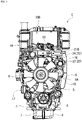
Fig. 1 is a front view of an industrial diesel engine. -
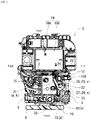
Fig. 2 is a plan view of the engine illustrated inFig. 1 . -
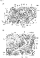
Fig. 3 is a left side view of the engine illustrated inFig. 1 . -
Fig. 4(A) is a perspective view of an upper main part of the engine illustrated inFig. 1 as viewed from the upper left front side, andFig. 4(B) is a perspective view illustrating a cooling water supply/discharge portion to/from a cylinder head cover. -
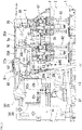
Fig. 5 is a plan view of the cylinder head cover and the like. -
Fig. 6 illustrates a heating mechanism, in which (A) is a plan view of a main part, and (B) is a right side view of the main part. -
Fig. 7 is a transverse cross-sectional view of a main part illustrating the heating mechanism. -
Fig. 8 is a partially cutaway side view illustrating a structure near a cylinder head and a head cover. -
Fig. 9 is a cross-sectional view illustrating the structure of an oil separator as viewed from the side. -
Fig. 10 is a front view of the oil separator. -
Fig. 11 is a plan view of the oil separator. - Hereinafter, an embodiment of a blow-by gas recirculation device according to the present invention, when applied to an industrial diesel engine, will be described with reference to the drawings.
- In a diesel engine E to be applied to industrial machines such as agricultural machines and construction machines, a
cylinder head 2 is assembled on acylinder block 1, a cylinder head cover (hereinafter, abbreviated as a "head cover") 3 is assembled on thecylinder head 2, and anoil pan 4 is assembled under thecylinder block 1, as illustrated inFigs. 1 to 4 . - A
transmission case 5 is assembled to a front end portion of thecylinder block 1, anengine cooling fan 6 is disposed in a front portion of thetransmission case 5, and aflywheel housing 7 is disposed in a rear portion of thecylinder block 1. The upper half portion of thecylinder block 1 is formed in acylinder 1A, and the lower half portion is formed in acrankcase 1B. - A
drive pulley 8 to be attached to a shaft end of a crankshaft (not illustrated), afan pulley 6A for driving theengine cooling fan 6, atransmission belt 10 extending over apassive pulley 9A of a dynamo (alternator) 9, awater flange 30, and the like are mounted on a front portion of the engine E. Anexhaust manifold 11, asupercharger 12, astarter 13, anEGR cooler 14, and the like are mounted on the left side of the engine E. Anintake manifold 15, anoil filter 17, and the like are mounted on the right side of the engine E. A compressor downstream suction passage (secondary air passage) 18 (seeFig. 2 ) is disposed in an upper portion of the engine E. - An exhaust
gas treatment device 19 is provided in an upper portion and a rear portion of the engine E. The exhaustgas treatment device 19 has an exhaust gas primary treatment device (DPF, etc.) 19A disposed in an upper portion of theflywheel housing 7 in the rear portion of the engine E, and an exhaust gas secondary treatment device (SCR, DOC, etc.) 19B disposed close to the rear portion of thehead cover 3 in the upper portion of the engine E. The exhaustgas treatment device 19 is supported by amounting frame 16 bolted to thecylinder block 1. - An intake passage a is a general term including a compressor
upstream suction passage 20, the compressordownstream suction passage 18, and theintake manifold 15. The compressorupstream suction passage 20 is the intake passage a formed of a pipe connecting an air cleaner (not illustrated) and acompressor housing 12A of the supercharger (turbocharger) 12. The compressordownstream suction passage 18 is the intake passage a formed of a pipe connecting thecompressor housing 12A and theintake manifold 15. - As illustrated in
Figs. 1 to 3 andFig. 4(A) , a blow-by gas recirculation device A that returns blow-by gas in thecrankcase 1B to the intake passage a by using a blow-by gas passage w including an in-cover gas passage 3A (seeFig. 5 ) formed inside thehead cover 3 is mounted on the engine E. The blow-by gas passage w has agas duct 21 connecting the upper left side of thehead cover 3 and the compressorupstream suction passage 20. Thegas duct 21 is formed in a curved pipeline connecting a blow-by gas outlet (not illustrated) of thehead cover 3 and astraight pipe 23. - As illustrated in
Figs. 1 to 3 andFig. 4(A) , the compressorupstream suction passage 20 includes a connectingpipe 29 externally fitted to an inlet cylinder (not illustrated) of thecompressor housing 12A, thestraight pipe 23 internally fitted and connected to the connectingpipe 29, and an air pipe (not illustrated) connecting thestraight pipe 23 and the air cleaner (not illustrated). In thestraight pipe 23, an inrush pipe (not illustrated) serving as a terminal portion of the blow-by gas passage w is formed in a laterally branched shape, and aheating mechanism 22 capable of warming the inrush pipe portion in thestraight pipe 23 by using cooling water r is integrally provided. - Next, the configuration of the portion of the
head cover 3 in the blow-by gas recirculation device A will be described. As illustrated inFigs. 5 and8 , the in-cover gas passage 3A mainly includes anoil separator 25 and a positive crankcase ventilation (PCV) valve (an example of a pressure regulating valve) B housed in an upper portion of thehead cover 3 covering a valve mechanism F. Theoil separator 25 that traps and removes oil from the blow-by gas and the PCV valve B provided in a gas outlet portion (an example of the "outlet side of the blow-by gas passage") in thehead cover 3 are configured such that aseparator outlet 27, which is an outlet for the blow-by gas in theoil separator 25, is overlapped on a blow-bygas inlet portion 52 of the PCV valve B. - As illustrated in
Figs. 8 to 11 , theoil separator 25 has, in thehead cover 3, an outer shell shape similar to an inner upper portion of thehead cover 3 so as to be fitted into a space portion formed in a vertical clearance between atop wall 3a and the valve mechanism F without a gap (or with a small gap). Theoil separator 25 has aseparator inlet 35 that opens downward in the rear portion thereof, anoil filter 36 for trapping oil, adroplet collecting portion 37 that collects the trapped oil and drops them from a throughhole 37a, and a downward protrusion (an example of an oil dropping portion) 38 that drops the collected oil into the engine. Theseparator outlet 27 is a substantially D-shaped hole (seeFig. 11 ) located above thedownward protrusion 38. - As illustrated in
Figs. 8 to 11 , theoil separator 25 is formed in a long shape along the longitudinal direction (front-rear direction) of thehead cover 3, and can be divided into a separatorrear portion 25A having theseparator inlet 35, aseparator middle portion 25B having thedroplet collecting portion 37, and aseparator front portion 25C having theseparator outlet 27. Theoil filter 36 is located at a boundary between the separatorrear portion 25A and theseparator middle portion 25B, and thedownward protrusion 38 is formed in a lower portion of theseparator front portion 25C. - The separator
rear portion 25A is provided with a plate-shaped wall 25a protruding rearward in a horizontal posture on the upper side of theseparator inlet 35 located in the front portion of the separatorrear portion 25A. Therefore, it is configured such that the blow-by gas that has entered from theseparator inlet 35 is once detoured backward and then moved toward theoil filter 36 located in the upper front portion. - The
oil filter 36 is configured to have an impactor structure including a plurality ofnozzles 36a vertically lined in a horizontal posture and acollision plate 36b in a vertical posture disposed in front of the nozzles. The blow-by gas is accelerated by passing through thenozzle 36a, and when the accelerated blow-by gas vigorously collides with thecollision plate 36b, the oil contained in the blow-by gas is separated from the gas and dropped. Note that an orifice or a small diameter portion having a constant diameter may be adopted instead of thenozzle 36a, and in short, a means (passage) for increasing the speed of the blow-by gas may be adopted. These (nozzle, orifice, small diameter portion) may be collectively expressed as a speed increase path. - The separator
middle portion 25B is a portion where the oil that is trapped by theoil filter 36 and drops is dropped from thedroplet collecting portion 37 to a shallow bottom wall. The separatormiddle portion 25B is configured such that the oil that hits awall 25c above the boundary with theseparator front portion 25C and drops can also be guided to thedroplet collecting portion 37. The oil that has dropped from thedroplet collecting portion 37 can be stored on ashallow bottom wall 25b leading to the downward protrusion. - The
separator front portion 25C leading to the separatormiddle portion 25B is provided with theseparator outlet 27 in the upper portion, thedownward protrusion 38 in the lower portion, and apartition wall 25d for forming thedroplet collecting portion 37 in the vertical middle. In theseparator front portion 25C, theseparator outlet 27 is located at the highest position, and the height position of the upper surface (peripheral portion 27a described later) of a separator outlet 27d is set to be lower than the height positions of the upper surface of the separatorrear portion 25A and the upper surface of the separatormiddle portion 25B, the height positions being the same as each other, for convenience in disposing the pressure regulating valve B. - As illustrated in
Figs. 8 to 10 , anextension protrusion 38A further protruding downward is formed in thedownward protrusion 38, and acheck valve 39 is provided below the extension protrusion. The oil dropped from thedroplet collecting portion 37 can be stored in thedownward protrusion 38 to some extent, and is returned into the engine from the lower end of theextension protrusion 38A through thecheck valve 39. The valve mechanism F includes functional parts such as acamshaft 60, arocker arm 61, and a supply/discharge valve 62, and thedownward protrusion 38 is provided to protrude toward a gap portion avoiding these functional parts. - As illustrated in
Fig. 8 , aperipheral portion 52a of a surroundingspace portion 52, which is the blow-bygas inlet portion 52 of the pressure regulating valve B, and theperipheral portion 27a of theseparator outlet 27 are in vertical contact with each other. As a result, the surroundingspace portion 52 and theseparator outlet 27 are configured to communicate with each other. Therefore, in thehead cover 3, the blow-by gas that has entered theoil separator 25 from theseparator inlet 35 flows in the order of theoil filter 36, theseparator outlet 27, the pressure regulating valve B, and agas outlet portion 43. In addition, the oil trapped by theoil separator 25 is dropped into the engine from theextension projection 38A, but may be dropped from theseparator inlet 35. - As illustrated in
Figs. 4 to 6 , the PCV valve B acting on the in-cover gas passage 3A is configured in thehead cover 3 in a state of using thetop wall 3a of thehead cover 3. As illustrated inFig. 4(B) , the PCV valve B is a diaphragm valve, and acover lid 41 made of sheet metal material that enables assembly and removal of adiaphragm 40 is detachably attached to thetop wall 3a of thehead cover 3 by screwing or the like. By providing the PCV valve B on thehead cover 3 in a state of being exposed to the outside, there is an advantage that maintenance of the inside of the valve (replacement of thediaphragm 40 or the like) can be performed by attaching and detaching thecover lid 41 without removing thehead cover 3. - In the blow-by gas passage w of the blow-by gas recirculation device A, the configuration in which the PCV valve B having a diaphragm valve structure (may be referred to as a breather valve) is provided in the
head cover 3 is a well-known technique inJapanese Patent Application Laid-Open No. 2006 -22650 Japanese Patent Application Laid-Open No. 2004 -116395 - The PCV valve B is provided on the
top wall 3a using avalve installation hole 42 formed in thetop wall 3a, and the blow-by gas that has passed through the in-cover gas passage 3A and the PCV valve B flows out from thegas outlet portion 43 formed below thevalve installation hole 42 in a state of facing left front, and flows to thegas duct 21. That is, the PCV valve B is disposed in thegas outlet portion 43 in a state where most constituent elements thereof are formed on thetop wall 3a itself. Note that inFigs. 6(A) and7 ,reference numeral 51 denotes an annular valve seat,reference numeral 52 denotes a surrounding space portion communicating with the in-cover gas passage 3A,reference numeral 53 denotes a discharge passage, and reference numeral 53a denotes a discharge passage inlet. In addition, a plurality ofnut portions 3c for bolting thecover lid 41 to thetop wall 3a are formed near the periphery of thevalve installation hole 42. - As illustrated in
Figs. 4 to 7 , a temperature raising mechanism C capable of warming the PCV valve B is provided in thehead cover 3. The temperature raising mechanism C is configured by forming aflow path 44 for flowing the cooling water r near the PCV valve B on thetop wall 3a of thehead cover 3. Theflow path 44 is configured by forming a deep hole (lateral hole) that opens on the right side surface and extends leftward and laterally toward the PCV valve B in a thick width of thetop wall 3a. Theflow path 44 having a deep hole shape includes adeep hole portion 44A that extends laterally (leftward) and deeply in the rear portion of the hole, ashallow hole portion 44B that extends forward from the left-right intermediate portion of thedeep hole portion 44A, and anopening portion 44C that is long in the front-rear direction and extends over the opening sides of both thehole portions flow path 44 is formed in a lateral hole having an L shape in plan view (seeFig. 7 ). - As illustrated in
Figs. 4(B) ,6 , and7 , alid body 45 capable of closing theopening portion 44C of theflow path 44 is detachably attached to thehead cover 3 by twobolts lid body 45 is configured by integrally attaching aninlet pipe 47 and anoutlet pipe 48 to alid body portion 45A, and is liquid-tightly attached to a vertical mountingsurface 3b formed on the right side of thetop wall 3a using two mountingholes lid body portion 45A long in the front-rear direction. A gasket (not illustrated) may be provided between the mountingsurface 3b and thelid body 45 as necessary. - The
inlet pipe 47 is liquid-tightly and penetratingly supported by the rear portion of thelid body portion 45A, and atip portion 47a thereof is provided in a state of having a large insertion amount so as to reach ahole bottom 44a portion of thedeep hole portion 44A. Theoutlet pipe 48 is an outlet for a fluid with respect to the deep hole, and is liquid-tightly and internally fitted in anoutlet protrusion 45B formed in the front portion of thelid body portion 45A. On the inner surface of thelid body portion 45A, adischarge introduction recess 49 located in theoutlet protrusion 45B and aflat recess 50 that is long in the front-rear direction and extremely shallow are continuously formed. When thelid body 45 is assembled to thehead cover 3, thedischarge introduction recess 49 and theflat recess 50 are configured such that they face theopening portion 44C with substantially the same dimensions. - In the temperature raising mechanism C, the cooling water r enters the
hole bottom 44a portion of thedeep hole portion 44A from theinlet pipe 47, and then flows to thedeep hole portion 44A, theshallow hole portion 44B, thedischarge introduction recess 49, and theoutlet pipe 48. When the cooling water r flows through theflow path 44, the heat of the cooling water r is conducted to avalve structure portion 58 and a surroundingportion 59 of the PCV valve B on thehead cover 3, so that the temperature of the PCV valve B can be quickly and efficiently raised. Asupply pipe 54 for the cooling water r is connected to theinlet pipe 47, and adischarge pipe 55 is connected to the outlet pipe 48 [seeFig. 4(B) ]. - With the temperature raising mechanism C, the temperature of the cooling water r is quickly raised with the start of the engine, and the PCV valve B is warmed from the inside by the cooling water r that has become a warm fluid, even if the PCV valve B whose
lid body 45 is exposed to the outside freezes in extremely cold weather such as winter. Therefore, the moisture in the blow-by gas is prevented from freezing in the PCV valve B, and the blow-by gas recirculation device A in which the PCV valve B works well can be realized. In addition, theflow path 44 is formed in thehead cover 3 itself, so that it is not necessary to provide another dedicated flow path and the temperature raising mechanism C that is economical and space-saving can be realized, and the temperature of the PCV valve B can be quickly and efficiently raised from thevalve structure portion 58 that is the central portion thereof. - As illustrated in
Figs. 4(B) ,6(A), and 6(B) , abase portion 56 for an air bleeding portion (air bleeding) D to act on the blow-by gas passage w is formed in thelid body 45. The air bleeding portion D includes thebase portion 56 and a bleedingoperation tool 57 attached to the base portion. Thebase portion 56 is formed in theoutlet protrusion 45B in a state of having avertical hole 56a communicating with thedischarge introduction recess 49. The bleedingoperation tool 57 illustrated inFig. 6(B) [not illustrated inFig. 4(B) ] is configured by, for example, a screw plug or a union bolt, but is not limited thereto. - Since the PCV valve B and the
lid body 45 are located at the highest position in the blow-by gas passage w, there is a merit that air bleeding for the blow-by gas passage w can be performed by one air bleeding portion D provided in thelid body 45. Moreover, thelid body 45 has a reasonable structure that serves as both a constituent member of the temperature raising mechanism C and a main part (base portion 56) of the air bleeding portion D, which is advantageous in terms of cost reduction, size reduction, simplification of configuration, and the like. - As illustrated in
Figs. 1 to 3 , aheating mechanism 22 capable of heating a recirculation passage portion k in which the blow-by gas passage w is communicatively connected to the intake passage a is mounted. The recirculation passage portion k is configured as a portion where theinrush pipe 28, which is the terminal portion of the blow-by gas passage w, and the straight pipe 23 (intake passage a) are obliquely and communicatively connected. - The
heating mechanism 22 is formed by attaching apipeline 24 through which the cooling water r passes to the recirculation passage portion k, and a cooling water inlet portion (not illustrated) made of a metal pipe is liquid-tightly provided below thepipeline 24 made of a metal pipe, and a coolingwater outlet portion 26 made of a metal pipe is liquid-tightly provided above thepipeline 24. Thepipeline 24 is attached in a state of straddling and being in contact with both thestraight pipe 23 and theinrush pipe 28 by welding (welding or the like). - A
first connection tube 34 that connects a branched pipe (reference sign is omitted) from an EGR cooler coolingwater pipe 32 and a cooling water inlet portion (not illustrated) and asecond connection tube 33 that connects awater pump 31 and the coolingwater outlet portion 26 are provided. For example, the cooling water r enters thepipeline 24 from the cooling water inlet portion on the lower side (not illustrated), is thermally conducted to the recirculation passage portion k when passing through thepipeline 24, and then exits from the coolingwater outlet portion 26 on the upper side. - It is possible to obtain an advantage that troubles, in which in extremely cold weather the moisture in the blow-by gas recirculated into the
inrush pipe 28 and thestraight pipe 23 freezes by being cooled by low-temperature fresh air and the internal passage of theinrush pipe 28 is narrowed or clogged by the freezing, does not occur. Thestraight pipe 23, theinrush pipe 28, and thepipeline 24 are metal pipes, and the recirculation passage portion k is excellent in thermal conductivity, so that blow-by gas g and cold fresh air can be warmed by the heat of the cooling water r. - The
oil filter 36 to be installed in theoil separator 25 may have a structure other than the impactor structure. - The pressure regulating valve B may be a valve having a structure other than the diaphragm valve.
-
- 1B: Crankcase
- 3: Head cover
- 3A: In-cover gas passage
- 25: Oil separator
- 27: Separator outlet
- 35: Separator inlet
- 36: Oil filter
- 36a: Nozzle
- 36b: Collision plate
- 38: Oil dropping portion
- 39: Check valve
- 40: Diaphragm
- 41: Cover lid
- B: Pressure regulating valve
- F: Valve mechanism
- a: Intake passage
Claims (8)
- A blow-by gas recirculation device configured to guide blow-by gas from a crankcase to an intake passage through an in-cover gas passage formed inside a head cover, whereinan oil separator that traps and removes oil from the blow-by gas is attached to an inside of the head cover,a pressure regulating valve is provided on an outlet side of the in-cover gas passage in the head cover, anda separator outlet, which is an outlet for the blow-by gas in the oil separator, is overlapped on a blow-by gas inlet portion of the pressure regulating valve.
- The blow-by gas recirculation device according to claim 1, wherein the pressure regulating valve is disposed in a gas outlet portion of the in-cover gas passage with respect to the head cover.
- The blow-by gas recirculation device according to claim 1 or claim 2, wherein the pressure regulating valve is a diaphragm valve, and a cover lid that enables assembly and removal of a diaphragm is detachably attached to the cylinder head cover.
- The blow-by gas recirculation device according to any one of claims 1 to 3, wherein the oil separator includes a separator inlet through which the blow-by gas is introduced, an oil filter, an oil dropping portion, and the separator outlet through which the blow-by gas is discharged.
- The blow-by gas recirculation device according to claim 4, wherein the oil filter has an impactor structure including a nozzle and a collision plate.
- The blow-by gas recirculation device according to claim 4 or claim 5, wherein the oil dropping portion protrudes toward a gap portion of a valve mechanism provided inside the head cover.
- The blow-by gas recirculation device according to any one of claims 4 to 6, wherein a check valve that allows a downward movement of the oil and prevents an upward movement of the oil is provided in a lower end portion of the oil dropping portion.
- The blow-by gas recirculation device according to any one of claims 1 to 6, wherein the oil separator is formed in a long shape along a longitudinal direction of the head cover.
Applications Claiming Priority (2)
| Application Number | Priority Date | Filing Date | Title |
|---|---|---|---|
| JP2019109378 | 2019-06-12 | ||
| PCT/JP2020/016470 WO2020250566A1 (en) | 2019-06-12 | 2020-04-14 | Blow-by gas recirculating device |
Publications (3)
| Publication Number | Publication Date |
|---|---|
| EP3985234A1 true EP3985234A1 (en) | 2022-04-20 |
| EP3985234A4 EP3985234A4 (en) | 2023-07-05 |
| EP3985234B1 EP3985234B1 (en) | 2025-05-14 |
Family
ID=73781758
Family Applications (1)
| Application Number | Title | Priority Date | Filing Date |
|---|---|---|---|
| EP20822942.7A Active EP3985234B1 (en) | 2019-06-12 | 2020-04-14 | Blow-by gas recirculating device |
Country Status (4)
| Country | Link |
|---|---|
| US (1) | US11635006B2 (en) |
| EP (1) | EP3985234B1 (en) |
| JP (1) | JP7343580B2 (en) |
| WO (1) | WO2020250566A1 (en) |
Families Citing this family (1)
| Publication number | Priority date | Publication date | Assignee | Title |
|---|---|---|---|---|
| JP2025101881A (en) * | 2023-12-26 | 2025-07-08 | 株式会社クボタ | engine |
Family Cites Families (26)
| Publication number | Priority date | Publication date | Assignee | Title |
|---|---|---|---|---|
| DE19700733C2 (en) * | 1997-01-11 | 2001-11-22 | Bayerische Motoren Werke Ag | Crankcase ventilation through the cylinder head cover with integrated additional functions |
| JP4082973B2 (en) | 2002-09-26 | 2008-04-30 | 株式会社クボタ | engine |
| JP4320284B2 (en) | 2004-07-06 | 2009-08-26 | 株式会社クボタ | Engine breather equipment |
| JP2006022700A (en) * | 2004-07-07 | 2006-01-26 | Toyota Motor Corp | Blow-by gas reduction device |
| DE502007004245D1 (en) * | 2007-02-19 | 2010-08-12 | Bayer Materialscience Ag | Crankcase breather for an internal combustion engine |
| CN201041060Y (en) * | 2007-05-09 | 2008-03-26 | 无锡开普动力有限公司 | Aeration device of engine |
| JP4954114B2 (en) * | 2008-02-18 | 2012-06-13 | 愛知機械工業株式会社 | Blowby gas recirculation structure and internal combustion engine having the same |
| JP5290732B2 (en) * | 2008-12-22 | 2013-09-18 | 株式会社マーレ フィルターシステムズ | Oil separator for internal combustion engine |
| CN103987928B (en) * | 2011-10-20 | 2017-07-21 | 唐纳森公司 | Air/oil separators component, part and method |
| JP2015158132A (en) * | 2012-06-01 | 2015-09-03 | 株式会社マーレ フィルターシステムズ | Internal combustion engine oil separator |
| JP6092746B2 (en) * | 2013-10-01 | 2017-03-08 | 株式会社ニフコ | Oil separator |
| KR101544727B1 (en) * | 2014-06-17 | 2015-08-17 | 인지컨트롤스 주식회사 | Separator for internal-combustion engine |
| EP2963258A1 (en) * | 2014-06-30 | 2016-01-06 | MANN+HUMMEL GmbH | Oil mist separator and device for a crankcase ventilation |
| DE102014013714B4 (en) * | 2014-09-17 | 2025-07-03 | Mercedes-Benz Group AG | Internal combustion engine, especially for a motor vehicle |
| JP6412424B2 (en) * | 2014-12-18 | 2018-10-24 | 株式会社マーレ フィルターシステムズ | Oil mist separator |
| CN106246286B (en) * | 2015-06-11 | 2020-05-12 | 株式会社久保田 | Engine |
| JP2017141770A (en) * | 2016-02-12 | 2017-08-17 | 株式会社クボタ | Engine head cover |
| JP6660854B2 (en) | 2016-09-02 | 2020-03-11 | 株式会社クボタ | Oil separator exterior engine |
| JP6650865B2 (en) * | 2016-12-16 | 2020-02-19 | 株式会社クボタ | Engine head cover |
| CN107023348A (en) * | 2017-06-02 | 2017-08-08 | 广西玉柴机器股份有限公司 | Built-in integration type oil-gas separator |
| CN107152324B (en) * | 2017-06-09 | 2018-06-22 | 汉格斯特滤清系统(昆山)有限公司 | A kind of gs-oil separator |
| JP6774388B2 (en) * | 2017-06-29 | 2020-10-21 | 株式会社クボタ | Engine breather device |
| JP2019011709A (en) * | 2017-06-30 | 2019-01-24 | 株式会社マキタ | Lubrication device of engine and portable work machine |
| CN107939479B (en) * | 2017-12-28 | 2024-02-02 | 美嘉帕拉斯特汽车零部件(上海)有限公司 | Oil-gas separation device |
| CN109236416A (en) * | 2018-09-14 | 2019-01-18 | 广西玉柴机器股份有限公司 | A kind of iris type voltage adaptive controlling oil-gas separating device of engine |
| CN109113833B (en) * | 2018-09-26 | 2024-02-13 | 绵阳新晨动力机械有限公司 | Dual-cavity independent oil-gas separator |
-
2020
- 2020-04-14 WO PCT/JP2020/016470 patent/WO2020250566A1/en not_active Ceased
- 2020-04-14 JP JP2021525926A patent/JP7343580B2/en active Active
- 2020-04-14 EP EP20822942.7A patent/EP3985234B1/en active Active
- 2020-04-14 US US17/616,262 patent/US11635006B2/en active Active
Also Published As
| Publication number | Publication date |
|---|---|
| JP7343580B2 (en) | 2023-09-12 |
| WO2020250566A1 (en) | 2020-12-17 |
| JPWO2020250566A1 (en) | 2020-12-17 |
| US11635006B2 (en) | 2023-04-25 |
| EP3985234B1 (en) | 2025-05-14 |
| EP3985234A4 (en) | 2023-07-05 |
| US20220251986A1 (en) | 2022-08-11 |
Similar Documents
| Publication | Publication Date | Title |
|---|---|---|
| CN103180557B (en) | Pcv valve installation structure | |
| EP2853726B1 (en) | Engine | |
| US12215641B2 (en) | Engine | |
| EP3985234B1 (en) | Blow-by gas recirculating device | |
| JP6982542B2 (en) | Engine with blow-by gas recirculation device | |
| US10323614B2 (en) | Supercharged engine | |
| JP7157012B2 (en) | Engine with blow-by gas recirculation device | |
| EP3569832B1 (en) | Engine that includes blow-by-gas returning system | |
| JP7092658B2 (en) | Industrial engine with EGR cooler | |
| JP7103928B2 (en) | Blow-by gas recirculation device | |
| JP2022056070A (en) | Blow-by gas treatment device and engine including blow-by gas treatment device | |
| JP7385091B2 (en) | A blow-by gas treatment device and an engine equipped with a blow-by gas treatment device | |
| JP7109405B2 (en) | Blow-by gas reflux device | |
| JP2009209813A (en) | Blow-by gas recirculation device of engine | |
| EP3517769B1 (en) | Engine intake and exhaust system and internal combustion engine | |
| JP7712247B2 (en) | Head cover structure | |
| JP7232055B2 (en) | Engine with blow-by gas recirculation device | |
| JP7291642B2 (en) | Engine with blow-by gas recirculation device | |
| JP7081976B2 (en) | Engine with blow-by gas recirculation device | |
| JP7157011B2 (en) | Engine with blow-by gas recirculation device | |
| JP2021099052A (en) | Engine with ventilation device | |
| JP2022061558A (en) | Engine with blow-by gas treatment and blow-by gas treatment | |
| JP7291644B2 (en) | Engine with blow-by gas recirculation device | |
| JP7490713B2 (en) | Water-cooled engine | |
| JP7092690B2 (en) | Engine with blow-by gas recirculation device |
Legal Events
| Date | Code | Title | Description |
|---|---|---|---|
| STAA | Information on the status of an ep patent application or granted ep patent |
Free format text: STATUS: THE INTERNATIONAL PUBLICATION HAS BEEN MADE |
|
| PUAI | Public reference made under article 153(3) epc to a published international application that has entered the european phase |
Free format text: ORIGINAL CODE: 0009012 |
|
| STAA | Information on the status of an ep patent application or granted ep patent |
Free format text: STATUS: REQUEST FOR EXAMINATION WAS MADE |
|
| 17P | Request for examination filed |
Effective date: 20211129 |
|
| AK | Designated contracting states |
Kind code of ref document: A1 Designated state(s): AL AT BE BG CH CY CZ DE DK EE ES FI FR GB GR HR HU IE IS IT LI LT LU LV MC MK MT NL NO PL PT RO RS SE SI SK SM TR |
|
| DAV | Request for validation of the european patent (deleted) | ||
| DAX | Request for extension of the european patent (deleted) | ||
| A4 | Supplementary search report drawn up and despatched |
Effective date: 20230607 |
|
| RIC1 | Information provided on ipc code assigned before grant |
Ipc: F02F 7/00 20060101ALI20230601BHEP Ipc: F01M 13/04 20060101ALI20230601BHEP Ipc: B01D 45/08 20060101ALI20230601BHEP Ipc: F01M 13/00 20060101AFI20230601BHEP |
|
| STAA | Information on the status of an ep patent application or granted ep patent |
Free format text: STATUS: EXAMINATION IS IN PROGRESS |
|
| 17Q | First examination report despatched |
Effective date: 20240726 |
|
| GRAP | Despatch of communication of intention to grant a patent |
Free format text: ORIGINAL CODE: EPIDOSNIGR1 |
|
| STAA | Information on the status of an ep patent application or granted ep patent |
Free format text: STATUS: GRANT OF PATENT IS INTENDED |
|
| GRAS | Grant fee paid |
Free format text: ORIGINAL CODE: EPIDOSNIGR3 |
|
| INTG | Intention to grant announced |
Effective date: 20250227 |
|
| GRAA | (expected) grant |
Free format text: ORIGINAL CODE: 0009210 |
|
| STAA | Information on the status of an ep patent application or granted ep patent |
Free format text: STATUS: THE PATENT HAS BEEN GRANTED |
|
| AK | Designated contracting states |
Kind code of ref document: B1 Designated state(s): AL AT BE BG CH CY CZ DE DK EE ES FI FR GB GR HR HU IE IS IT LI LT LU LV MC MK MT NL NO PL PT RO RS SE SI SK SM TR |
|
| REG | Reference to a national code |
Ref country code: GB Ref legal event code: FG4D |
|
| REG | Reference to a national code |
Ref country code: CH Ref legal event code: EP |
|
| REG | Reference to a national code |
Ref country code: DE Ref legal event code: R096 Ref document number: 602020051352 Country of ref document: DE |
|
| REG | Reference to a national code |
Ref country code: IE Ref legal event code: FG4D |
|
| REG | Reference to a national code |
Ref country code: NL Ref legal event code: MP Effective date: 20250514 |
|
| PG25 | Lapsed in a contracting state [announced via postgrant information from national office to epo] |
Ref country code: PT Free format text: LAPSE BECAUSE OF FAILURE TO SUBMIT A TRANSLATION OF THE DESCRIPTION OR TO PAY THE FEE WITHIN THE PRESCRIBED TIME-LIMIT Effective date: 20250915 Ref country code: FI Free format text: LAPSE BECAUSE OF FAILURE TO SUBMIT A TRANSLATION OF THE DESCRIPTION OR TO PAY THE FEE WITHIN THE PRESCRIBED TIME-LIMIT Effective date: 20250514 Ref country code: ES Free format text: LAPSE BECAUSE OF FAILURE TO SUBMIT A TRANSLATION OF THE DESCRIPTION OR TO PAY THE FEE WITHIN THE PRESCRIBED TIME-LIMIT Effective date: 20250514 |
|
| REG | Reference to a national code |
Ref country code: LT Ref legal event code: MG9D |
|
| PG25 | Lapsed in a contracting state [announced via postgrant information from national office to epo] |
Ref country code: NO Free format text: LAPSE BECAUSE OF FAILURE TO SUBMIT A TRANSLATION OF THE DESCRIPTION OR TO PAY THE FEE WITHIN THE PRESCRIBED TIME-LIMIT Effective date: 20250814 Ref country code: GR Free format text: LAPSE BECAUSE OF FAILURE TO SUBMIT A TRANSLATION OF THE DESCRIPTION OR TO PAY THE FEE WITHIN THE PRESCRIBED TIME-LIMIT Effective date: 20250815 |
|
| PG25 | Lapsed in a contracting state [announced via postgrant information from national office to epo] |
Ref country code: NL Free format text: LAPSE BECAUSE OF FAILURE TO SUBMIT A TRANSLATION OF THE DESCRIPTION OR TO PAY THE FEE WITHIN THE PRESCRIBED TIME-LIMIT Effective date: 20250514 Ref country code: PL Free format text: LAPSE BECAUSE OF FAILURE TO SUBMIT A TRANSLATION OF THE DESCRIPTION OR TO PAY THE FEE WITHIN THE PRESCRIBED TIME-LIMIT Effective date: 20250514 |
|
| REG | Reference to a national code |
Ref country code: AT Ref legal event code: MK05 Ref document number: 1794927 Country of ref document: AT Kind code of ref document: T Effective date: 20250514 |
|
| PG25 | Lapsed in a contracting state [announced via postgrant information from national office to epo] |
Ref country code: BG Free format text: LAPSE BECAUSE OF FAILURE TO SUBMIT A TRANSLATION OF THE DESCRIPTION OR TO PAY THE FEE WITHIN THE PRESCRIBED TIME-LIMIT Effective date: 20250514 |
|
| PG25 | Lapsed in a contracting state [announced via postgrant information from national office to epo] |
Ref country code: HR Free format text: LAPSE BECAUSE OF FAILURE TO SUBMIT A TRANSLATION OF THE DESCRIPTION OR TO PAY THE FEE WITHIN THE PRESCRIBED TIME-LIMIT Effective date: 20250514 |
|
| PG25 | Lapsed in a contracting state [announced via postgrant information from national office to epo] |
Ref country code: AT Free format text: LAPSE BECAUSE OF FAILURE TO SUBMIT A TRANSLATION OF THE DESCRIPTION OR TO PAY THE FEE WITHIN THE PRESCRIBED TIME-LIMIT Effective date: 20250514 |
|
| PG25 | Lapsed in a contracting state [announced via postgrant information from national office to epo] |
Ref country code: RS Free format text: LAPSE BECAUSE OF FAILURE TO SUBMIT A TRANSLATION OF THE DESCRIPTION OR TO PAY THE FEE WITHIN THE PRESCRIBED TIME-LIMIT Effective date: 20250814 |
|
| PG25 | Lapsed in a contracting state [announced via postgrant information from national office to epo] |
Ref country code: IS Free format text: LAPSE BECAUSE OF FAILURE TO SUBMIT A TRANSLATION OF THE DESCRIPTION OR TO PAY THE FEE WITHIN THE PRESCRIBED TIME-LIMIT Effective date: 20250914 |
|
| PG25 | Lapsed in a contracting state [announced via postgrant information from national office to epo] |
Ref country code: LV Free format text: LAPSE BECAUSE OF FAILURE TO SUBMIT A TRANSLATION OF THE DESCRIPTION OR TO PAY THE FEE WITHIN THE PRESCRIBED TIME-LIMIT Effective date: 20250514 |
|
| PG25 | Lapsed in a contracting state [announced via postgrant information from national office to epo] |
Ref country code: DK Free format text: LAPSE BECAUSE OF FAILURE TO SUBMIT A TRANSLATION OF THE DESCRIPTION OR TO PAY THE FEE WITHIN THE PRESCRIBED TIME-LIMIT Effective date: 20250514 Ref country code: SM Free format text: LAPSE BECAUSE OF FAILURE TO SUBMIT A TRANSLATION OF THE DESCRIPTION OR TO PAY THE FEE WITHIN THE PRESCRIBED TIME-LIMIT Effective date: 20250514 |
|
| PG25 | Lapsed in a contracting state [announced via postgrant information from national office to epo] |
Ref country code: CZ Free format text: LAPSE BECAUSE OF FAILURE TO SUBMIT A TRANSLATION OF THE DESCRIPTION OR TO PAY THE FEE WITHIN THE PRESCRIBED TIME-LIMIT Effective date: 20250514 |
|
| PG25 | Lapsed in a contracting state [announced via postgrant information from national office to epo] |
Ref country code: EE Free format text: LAPSE BECAUSE OF FAILURE TO SUBMIT A TRANSLATION OF THE DESCRIPTION OR TO PAY THE FEE WITHIN THE PRESCRIBED TIME-LIMIT Effective date: 20250514 |
|
| PG25 | Lapsed in a contracting state [announced via postgrant information from national office to epo] |
Ref country code: RO Free format text: LAPSE BECAUSE OF FAILURE TO SUBMIT A TRANSLATION OF THE DESCRIPTION OR TO PAY THE FEE WITHIN THE PRESCRIBED TIME-LIMIT Effective date: 20250514 Ref country code: SK Free format text: LAPSE BECAUSE OF FAILURE TO SUBMIT A TRANSLATION OF THE DESCRIPTION OR TO PAY THE FEE WITHIN THE PRESCRIBED TIME-LIMIT Effective date: 20250514 |
|
| PG25 | Lapsed in a contracting state [announced via postgrant information from national office to epo] |
Ref country code: IT Free format text: LAPSE BECAUSE OF FAILURE TO SUBMIT A TRANSLATION OF THE DESCRIPTION OR TO PAY THE FEE WITHIN THE PRESCRIBED TIME-LIMIT Effective date: 20250514 |
|
| REG | Reference to a national code |
Ref country code: DE Ref legal event code: R097 Ref document number: 602020051352 Country of ref document: DE |
|
| PLBE | No opposition filed within time limit |
Free format text: ORIGINAL CODE: 0009261 |
|
| STAA | Information on the status of an ep patent application or granted ep patent |
Free format text: STATUS: NO OPPOSITION FILED WITHIN TIME LIMIT |
|
| REG | Reference to a national code |
Ref country code: CH Ref legal event code: L10 Free format text: ST27 STATUS EVENT CODE: U-0-0-L10-L00 (AS PROVIDED BY THE NATIONAL OFFICE) Effective date: 20260325 |
|
| PGFP | Annual fee paid to national office [announced via postgrant information from national office to epo] |
Ref country code: GB Payment date: 20260313 Year of fee payment: 7 |
|
| PGFP | Annual fee paid to national office [announced via postgrant information from national office to epo] |
Ref country code: FR Payment date: 20260309 Year of fee payment: 7 |
|
| 26N | No opposition filed |
Effective date: 20260217 |