EP3984784A1 - Luftloser reifen, stromversorgungsvorrichtung für beglichen körper und beweglicher körper - Google Patents
Luftloser reifen, stromversorgungsvorrichtung für beglichen körper und beweglicher körper Download PDFInfo
- Publication number
- EP3984784A1 EP3984784A1 EP20822534.2A EP20822534A EP3984784A1 EP 3984784 A1 EP3984784 A1 EP 3984784A1 EP 20822534 A EP20822534 A EP 20822534A EP 3984784 A1 EP3984784 A1 EP 3984784A1
- Authority
- EP
- European Patent Office
- Prior art keywords
- annular body
- pneumatic tire
- inner annular
- electrode portion
- tire
- Prior art date
- Legal status (The legal status is an assumption and is not a legal conclusion. Google has not performed a legal analysis and makes no representation as to the accuracy of the status listed.)
- Pending
Links
Images


Classifications
-
- B—PERFORMING OPERATIONS; TRANSPORTING
- B60—VEHICLES IN GENERAL
- B60B—VEHICLE WHEELS; CASTORS; AXLES FOR WHEELS OR CASTORS; INCREASING WHEEL ADHESION
- B60B9/00—Wheels of high resiliency, e.g. with conical interacting pressure-surfaces
-
- B—PERFORMING OPERATIONS; TRANSPORTING
- B60—VEHICLES IN GENERAL
- B60B—VEHICLE WHEELS; CASTORS; AXLES FOR WHEELS OR CASTORS; INCREASING WHEEL ADHESION
- B60B5/00—Wheels, spokes, disc bodies, rims, hubs, wholly or predominantly made of non-metallic material
- B60B5/02—Wheels, spokes, disc bodies, rims, hubs, wholly or predominantly made of non-metallic material made of synthetic material
-
- B—PERFORMING OPERATIONS; TRANSPORTING
- B60—VEHICLES IN GENERAL
- B60C—VEHICLE TYRES; TYRE INFLATION; TYRE CHANGING; CONNECTING VALVES TO INFLATABLE ELASTIC BODIES IN GENERAL; DEVICES OR ARRANGEMENTS RELATED TO TYRES
- B60C19/00—Tyre parts or constructions not otherwise provided for
-
- B—PERFORMING OPERATIONS; TRANSPORTING
- B60—VEHICLES IN GENERAL
- B60C—VEHICLE TYRES; TYRE INFLATION; TYRE CHANGING; CONNECTING VALVES TO INFLATABLE ELASTIC BODIES IN GENERAL; DEVICES OR ARRANGEMENTS RELATED TO TYRES
- B60C7/00—Non-inflatable or solid tyres
- B60C7/10—Non-inflatable or solid tyres characterised by means for increasing resiliency
- B60C7/14—Non-inflatable or solid tyres characterised by means for increasing resiliency using springs
- B60C7/146—Non-inflatable or solid tyres characterised by means for increasing resiliency using springs extending substantially radially, e.g. like spokes
-
- B—PERFORMING OPERATIONS; TRANSPORTING
- B60—VEHICLES IN GENERAL
- B60C—VEHICLE TYRES; TYRE INFLATION; TYRE CHANGING; CONNECTING VALVES TO INFLATABLE ELASTIC BODIES IN GENERAL; DEVICES OR ARRANGEMENTS RELATED TO TYRES
- B60C7/00—Non-inflatable or solid tyres
- B60C7/22—Non-inflatable or solid tyres having inlays other than for increasing resiliency, e.g. for armouring
-
- B—PERFORMING OPERATIONS; TRANSPORTING
- B60—VEHICLES IN GENERAL
- B60C—VEHICLE TYRES; TYRE INFLATION; TYRE CHANGING; CONNECTING VALVES TO INFLATABLE ELASTIC BODIES IN GENERAL; DEVICES OR ARRANGEMENTS RELATED TO TYRES
- B60C9/00—Reinforcements or ply arrangement of pneumatic tyres
- B60C9/18—Structure or arrangement of belts or breakers, crown-reinforcing or cushioning layers
- B60C9/20—Structure or arrangement of belts or breakers, crown-reinforcing or cushioning layers built-up from rubberised plies each having all cords arranged substantially parallel
- B60C9/22—Structure or arrangement of belts or breakers, crown-reinforcing or cushioning layers built-up from rubberised plies each having all cords arranged substantially parallel the plies being arranged with all cords disposed along the circumference of the tyre
- B60C9/2204—Structure or arrangement of belts or breakers, crown-reinforcing or cushioning layers built-up from rubberised plies each having all cords arranged substantially parallel the plies being arranged with all cords disposed along the circumference of the tyre obtained by circumferentially narrow strip winding
-
- H—ELECTRICITY
- H02—GENERATION; CONVERSION OR DISTRIBUTION OF ELECTRIC POWER
- H02J—CIRCUIT ARRANGEMENTS OR SYSTEMS FOR SUPPLYING OR DISTRIBUTING ELECTRIC POWER; SYSTEMS FOR STORING ELECTRIC ENERGY
- H02J50/00—Circuit arrangements or systems for wireless supply or distribution of electric power
- H02J50/005—Mechanical details of housing or structure aiming to accommodate the power transfer means, e.g. mechanical integration of coils, antennas or transducers into emitting or receiving devices
-
- H—ELECTRICITY
- H02—GENERATION; CONVERSION OR DISTRIBUTION OF ELECTRIC POWER
- H02J—CIRCUIT ARRANGEMENTS OR SYSTEMS FOR SUPPLYING OR DISTRIBUTING ELECTRIC POWER; SYSTEMS FOR STORING ELECTRIC ENERGY
- H02J50/00—Circuit arrangements or systems for wireless supply or distribution of electric power
- H02J50/05—Circuit arrangements or systems for wireless supply or distribution of electric power using capacitive coupling
-
- B—PERFORMING OPERATIONS; TRANSPORTING
- B60—VEHICLES IN GENERAL
- B60B—VEHICLE WHEELS; CASTORS; AXLES FOR WHEELS OR CASTORS; INCREASING WHEEL ADHESION
- B60B9/00—Wheels of high resiliency, e.g. with conical interacting pressure-surfaces
- B60B9/02—Wheels of high resiliency, e.g. with conical interacting pressure-surfaces using springs resiliently mounted bicycle rims
- B60B9/04—Wheels of high resiliency, e.g. with conical interacting pressure-surfaces using springs resiliently mounted bicycle rims in leaf form
Definitions
- the present invention relates to a non-pneumatic tire, a mobile power supply device and a mobile that can be suitably used in a non-contact power supply system.
- non-contact power supply method As a method of supplying electric power to vehicles such as electric vehicles by non-contact (wireless) (non-contact power supply method), a so-called electric field power supply method is known (see PTL 1).
- a tire fitted to a rim wheel relays the electric field from the metal plate embedded in the road into the vehicle.
- power supply from the roadside to the vehicle can be performed, and the vehicle can also be operated while traveling.
- the non-pneumatic tire includes an inner annular body (also referred to as an inner cylinder) centered on a rotation axis portion, an outer annular body (also referred to as an outer cylinder) provided radially outward of the inner annular body, a connecting member elastically deforming and for connecting the inner annular body and the outer annular body, and a tread portion provided radially outward of the outer annular body and in contact with a road.
- an inner annular body also referred to as an inner cylinder
- an outer annular body also referred to as an outer cylinder
- a connecting member elastically deforming and for connecting the inner annular body and the outer annular body
- a tread portion provided radially outward of the outer annular body and in contact with a road.
- the connecting member and the outer annular body constituting the non-pneumatic tire are formed of a resin material, that is, a non-metallic material, the conductivity is lower and the transmission efficiency of power is lower than that of the metal rim wheel.
- an object of the present invention is to provide a non-pneumatic tire, a mobile power supply device and a mobile capable of improving the transmission efficiency of power supplied from the road side even when main components are formed of a non-metallic material.
- Non-pneumatic tire for example, non-pneumatic tire 10
- a wheel portion including an inner annular body (inner annular body 40) centered on a rotation axis portion (rotation axis portion 41), an outer annular body (outer annular body 50) provided radially outward of the inner annular body, and a connecting member (connecting member 60) elastically deforming and for connecting the inner annular body and the outer annular body and elastically deforming the inner annular body, and a tread portion (tread portion 20) provided radially outward of the outer annular body and in contact with the road (road 200).
- the non-pneumatic tire includes an electrode portion (electrode portion 70) provided inside the tread portion, or in contact with the tread portion, and radially inside the tread portion, and a wiring portion (wiring portion 80) for connecting the electrode portion and the inner annular body and formed of a conductor.
- electrode portion 70 electrode portion provided inside the tread portion, or in contact with the tread portion, and radially inside the tread portion
- wiring portion 80 for connecting the electrode portion and the inner annular body and formed of a conductor.
- At least a part of the wheel portion is formed of a non-metallic material
- the electrode portion is formed of a conductor having a predetermined width in tire width direction, and having a predetermined length in tire circumferential direction.
- FIG. 1 is an overall schematic configuration diagram of the power supply system 1 according to the present embodiment.
- the power supply system 1 includes a wheeled mobile 100 and a road 200.
- the non-pneumatic tire 10 is mounted on the wheeled mobile 100.
- FIG. 1 shows a schematic cross-sectional view of the wheeled mobile 100 (including the non-pneumatic tire 10) along the width direction and a schematic cross-sectional view of the road 200 along the width direction.
- the wheeled mobile 100 is a mobile moving on a road, and in the present embodiment, it is an electric wheelchair to which two non-pneumatic tire 10 are mounted.
- an auxiliary tire (not shown) for changing the direction may be mounted to the wheeled mobile 100.
- the wheeled mobile 100 is not limited to an electric wheelchair to which two non-pneumatic tire 10 s are mounted, and may be a handle-type electric wheelchair to which four non-pneumatic tire 10 s are mounted, i.e., a so-called senior-car (Registered trademark).
- the diameter size of the non-pneumatic tire 10 may be smaller than the diameter size shown in FIG. 1 .
- a pair of power transmission units 210 are embedded in the road 200 through which the wheeled mobile 100 passes.
- the pair of power transmission units 210 are embedded with a predetermined distance therebetween in the width direction of the road 200 (the direction orthogonal to the moving direction of the wheeled mobile 100) so as to correspond to the tread width (the width between the right and left tire) of the wheeled mobile 100.
- the road 200 is typically a road through which a vehicle passes or a pedestrian passage, but is not limited to a road or a passage as long as the transmission unit 210 can be installed in a place such as a floor of a building.
- a power supply device 220 is connected to the pair of power transmission units 210.
- the power supply device 220 supplies electric power to the wheeled mobile 100 through the power transmission unit 210.
- the power supply device 220 realizes a system (non-contact power supply system) in which power is supplied by non-contact (wireless) through the power transmission unit 210.
- Such a non-contact power supply system is called an electric field power supply system.
- a series resonance circuit is formed on both the power transmission side (the road 200 side) and the power reception side (the wheeled mobile 100 side), and power (AC power) is transmitted in a resonance state.
- the resonance frequency is about 100 kHz to 13 MHz.
- the non-pneumatic tire 10 is rotatably mounted to an axle 120 of the wheeled mobile 100 using a nut 110.
- the axle 120 is made of metal, and as will be described later, the non-pneumatic tire 10 mounted on the axle 120 is electrically connected to the axle 120.
- AC power is supplied from the power supply device 220 to a rectifying circuit 130 provided in the wheeled mobile 100 via the power transmission unit 210, the road 200, the non-pneumatic tire 10 and the axle 120.
- the rectifying circuit 130 supplies rectified DC power to a battery 140.
- the battery 140 supplies power to a moving motor (not shown) of the wheeled mobile 100.
- the battery 140 stores power supplied from the outside.
- the external power supply includes the power supply device 220 on the road 200 and a power supply connected to a charging socket (not shown). Since the power supply from the power supply device 220 to the battery 140 is non-contact (wireless) as described above, the battery can be charged even during the movement of the wheeled mobile 100.
- the power transmission unit 210 and the power supply device 220 on the road 200 side constitute the mobile power supply device for supplying power to the wheeled mobile 100 moving on the road 200.
- the wheeled mobile 100 constitutes a mobile fed from the mobile feeding device.
- FIG. 2 is an overall side view of the non-pneumatic tire 10.
- FIG. 3 is a partial cross-sectional view of the non-pneumatic tire 10 along the F3-F3 direction of FIG. 2 .
- the non-pneumatic tire 10 includes a tread portion 20 and a wheel portion 30.
- the tread portion 20 is a portion in contact with the road 200 (see FIG. 1 ) and is formed of a rubber material. On the surface of the tread portion 20 in contact with the road 200, a tread pattern may be formed according to the application of the wheeled mobile 100.
- the wheel portion 30 is composed of an inner annular body 40, an outer annular body 50 and a connecting member 60.
- the tread portion 20 is provided on the outside in the radial direction of the wheel portion 30.
- the inner annular body 40 has a rotation axis portion 41, spokes 42 and an annular portion 43.
- the inner annular body 40 is an annular body (also referred to as an inner cylinder) centered on the rotation axis portion 41.
- the rotation axis portion 41 is formed by an insertion hole through which the axle 120 of the wheeled mobile 100 is inserted, and the inner annular body 40 rotates around the rotation axis portion 41 (axle 120).
- the rotation axis portion 41 and the annular portion 43 are connected by a plurality of spokes 42 radially extending from the rotation axis portion 41.
- the outer annular body 50 is provided radially outward of the inner annular body 40.
- the outer annular body 50 is also an annular body (also referred to as an outer cylinder) having the rotation axis portion 41 as its center, and rotates around the rotation axis portion 41 (axle 120).
- the diameter size of the outer annular body 50 is larger than the diameter size of the inner annular body 40. That is, the outer annular body 50 is located radially outward from the inner annular body 40 at a predetermined distance.
- the connecting member 60 connects the inner annular body 40 and the outer annular body 50.
- a plurality of connecting members 60 are provided in the circumferential direction of the inner annular body 40 and the outer annular body 50.
- the connecting member 60 elastically deforms over a predetermined range (for example, about several centimeters.) when a load is applied.
- the wheel portion 30 is mainly formed of a resin material. However, a part of the wheel portion 30, specifically the rotation axis portion 41, is formed of a conductor, specifically a metal material. Portions requiring higher strength, such as the spokes 42, may also be formed of a metallic material. That is, at least a part of the wheel portion 30 is formed of a non-metallic material such as a resin material.
- An electrode portion 70 is provided radially inside the tread portion 20.
- the electrode portion 70 is in contact with the tread portion 20 and is provided radially inward of the tread portion 20. That is, the tread portion 20 is adjacent to the outer annular body 50 through the electrode portion 70, and is provided on the radially outer side of the outer annular body 50.
- the electrode portion 70 is in contact with the outer annular body 50 and is provided on the radially outer side of the outer annular body 50.
- the electrode portion 70 is formed of a conductor having a predetermined width in the tire width direction and a predetermined length in the tire circumferential direction.
- the electrode portion 70 is formed of a tape-like metal material (for example, aluminum tape).
- the electrode portion 70 is provided to cover the entire width of the outer annular body 50 in tire width direction. In other words, the electrode portion 70 is provided to cover the entire width of the tread portion 20 in the tire width direction.
- a wiring portion 80 connects the electrode portion 70 and the inner annular body 40.
- the wiring portion 80 is formed of a conductor such as a metal material.
- the wiring portion 80 is preferably formed by coating a core wire formed of a conductor with an insulating material such as vinyl.
- the wiring portion 80 connects the electrode portion 70 formed of a conductor and the conductor portion of the inner annular body 40. In this embodiment, the wiring portion 80 connects the electrode portion 70 and the rotation axis portion 41. In FIG. 3 , the wiring route of the wiring portion 80 is shown schematically in a straight line, but the wiring portion 80 is preferably crawled along the surface shape of the wheel portion 30.
- the wiring portion 80 may be connected to the electrode portion 70 through a through hole (not shown) formed in the wheel portion 30 (inner annular body 40 and outer annular body 50), or may be crawled along the surface of the wheel portion 30 and connected to the electrode portion 70.
- a through hole not shown
- the wiring portion 80 may connect the electrode portion 70 and the spokes 42.
- FIG. 4 is a partially enlarged side view of the non-pneumatic tire 10. Specifically, FIG. 4 is a partially enlarged side view of the non-pneumatic tire 10 including the annular portion 43 of inner annular body 40, the outer annular body 50, and the connecting member 60.
- the electrode portion 70 is an annular shape extending along the tire circumferential direction. That is, in this embodiment, the electrode portion 70 is provided along the outer circumferential surface of the outer annular body 50 (inner circumferential surface of the tread portion 20) over the entire circumferential direction. However, as described above, the electrode portion 70 may not necessarily be provided in the entire circumferential direction, and may have a predetermined length in tire circumferential direction so as not to greatly reduce the transmission efficiency of the electric power supplied from the side of the road 200.
- the wiring portion 80 is crawled along the surface of the connecting member 60.
- the wiring portion 80 is preferably fixed to the surface of the connecting member 60 by a method such as adhesion in order to prevent the wiring portion from floating.
- the wiring portion 80 is crawled along the front surface or the back surface of the connecting member 60 orthogonal to tire circumferential direction, not along the side surface of the connecting member 60.
- the wiring portion 80 is positioned on the side (inside) of the wheeled mobile 100 in a state where the non-pneumatic tire 10 is mounted on the wheeled mobile 100 (see FIG. 1 ).
- the non-pneumatic tire 10 for the right wheel and the non-pneumatic tire 10 for the left wheel are separately prepared.
- the non-pneumatic tire 10 may be attached to the wheeled mobile 100 such that the wiring portion 80 is positioned on the wheeled mobile 100 side (inside).
- the non-pneumatic tire 10 includes the electrode portion 70 which is in contact with the tread portion 20 and is provided on the radially inner side of the tread portion 20, and the wiring portion 80 which connects the electrode portion 70 and the inner annular body 40 and is formed of a conductor.
- the electrode portion 70 is formed of a conductor having a predetermined width in the tire width direction and a predetermined length in the tire circumferential direction.
- the electrode portion 70 provided radially inside the tread portion 20 and the inner annular body 40 in the vicinity of the axle 120 of the wheeled mobile 100 can be made conductive.
- the transmission efficiency of the electric power supplied from the road 200 side can be improved even when the main component of the non-pneumatic tire 10, specifically, at least a part of the wheel portion 30 is formed of a non-metallic material.
- tire radial direction inner end of the wiring portion 80 may not necessarily be connected to the rotation axis portion 41, but may be connected to the spokes 42 or the annular portion 43 of the inner annular body 40.
- the wiring portion 80 may be a standard wiring that does not take into consideration the extensibility or the like.
- the transmission efficiency of the power supplied from the side of the road 200 can be effectively improved by the extremely simple wiring.
- the electrode portion 70 is an annular shape extending along the tire circumferential direction. Accordingly, even if the non-pneumatic tire 10 rolls on the road 200, any portion of the electrode portion 70 is brought into a state of being close to the power transmission unit 210. Thus, the transmission efficiency of the power supplied from the side of the road 200 can be further improved.
- the power transmission unit 210 is wider than tire width, and the electrode portion 70 is provided to cover the entire width of the outer annular body 50 in the tire width direction. Therefore, the size of the electrode portion 70 in the tire width direction can be maximized. Thus, the transmission efficiency of the power supplied from the side of the road 200 can be further improved.
- the configuration of the non-pneumatic tire 10 described above may be modified to modified examples 1 to 5 described below.
- portions different from the above-described non-pneumatic tire 10 will be mainly described, and the same portions will be omitted as appropriate.
- FIG. 5 is a partially enlarged side view of a non-pneumatic tire 10 A of a modified example 1. As shown in FIG. 5 , the non-pneumatic tire 10 A is provided with a plate portion 81 between the outer annular body 50 and the electrode portion 70.
- the plate portion 81 is formed of a plate-like conductor and is connected to the wiring portion 80.
- the plate portion 81 can facilitate connection with the wiring portion 80 while securing a conductive area with the electrode portion 70.
- the transmission efficiency of the power supplied from the side of the road 200 can be further improved.
- the wiring portion 80 may be connected to the plate portion 81 through a through hole (not shown) formed in the outer annular body 50.
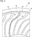
- FIG. 6 is a partially enlarged side view of a non-pneumatic tire 10 B of a modified example 2. As shown in FIG. 6 , in the non-pneumatic tire 10 B, the wiring portion 80 is embedded in the wheel portion 30.
- the wiring portion 80 is embedded in the outer annular body 50 and the connecting member 60. Accordingly, the wiring portion 80 is not exposed to the surface of the wheel portion 30. Thus, damage to the wiring portion 80 can be prevented.
- the wiring portion 80 can be embedded in the wheel portion 30 by being disposed at a predetermined position in the mold in advance when the wheel portion 30 is molded.
- FIG. 7 is a partial sectional view of a non-pneumatic tire 10 C of a modified example 3. Specifically, FIG. 7 is a partial cross-sectional view of a non-pneumatic tire 10 C along the tire width direction and the tire radial direction.
- the non-pneumatic tire 10 C includes a spiral belt 70 C.
- a cord 71 formed of a metal material is arranged along the tire circumferential direction in the spiral belt 70 C.
- the cord 71 is wound around the tire circumferential direction. In the case of the non-pneumatic tire 10 C, it is wound about 6 times along the tire circumferential direction. The number of turns of the cord 71 may vary depending on the performance required for the non-pneumatic tire 10 C.
- the electrode portion is also used by the cord 71 included in the spiral belt 70 C. Therefore, the wiring portion 80 is connected to the cord 71.
- the non-pneumatic tire 10 C there is no need to newly provide an electrode portion, and the transmission efficiency of power supplied from the side of the road 200 can be improved while suppressing an increase in manufacturing cost and weight.
- FIGS. 8 A and 8 B are partial front views and partial sectional views of a non-pneumatic tire 10 D of a modified example 4.
- FIG. 8 A shows a partial front view of the non-pneumatic tire 10 D along the tire width direction and the tire radial direction
- FIG. 8 B shows a partial sectional view of the non-pneumatic tire 10 D along the tire width direction and the tire radial direction.
- the non-pneumatic tire 10 D of the tread portion 20 is provided with a wide portion 21.
- a plurality of wide portions 21 are provided in the tire circumferential direction.
- tire four wide portions 21 is provided at 90 degree intervals in the tire circumferential direction.
- the number of the wide portions 21 is not particularly limited, but it is preferable to provide several to about 5 to 6 wide portions at appropriate intervals in the tire circumferential direction.
- the wide portion 21 is preferably positioned on the side (inner side) of the wheeled mobile 100 in a state that the non-pneumatic tire 10 D is mounted on the wheeled mobile.
- the outer annular body 50 also has a wide portion 52 and the electrode portion 70 also has a wide portion 72 so as to correspond to the wide portion 21. That is, in the non-pneumatic tire 10 D, a portion of the tread portion 20 and the electrode portion 70 in the tire circumferential direction have the wider portion 21 and the wider portion 72, respectively, which are wider than the other portions in the tire width direction.
- the transmission efficiency of the electric power supplied from the side of the road 200 can be improved.
- FIG. 9 is a schematic cross-sectional view of a non-pneumatic tire 10 E of a modified example 5 and the wheeled mobile 100 A mounted with the non-pneumatic tire 10 E. Specifically, FIG. 9 shows a schematic cross-sectional view of the wheeled mobile 100 A (including the non-pneumatic tire 10 E) along the width direction and a schematic cross-sectional view of the road 200 along the width direction.
- a pair of the power transmission units 210 are provided so as to face single non-pneumatic tire 10 E.
- an in-wheel motor 90 is provided inside the non-pneumatic tire 10 E. That is, the wheeled mobile 100 A is not provided with a motor for driving a wheel (tire).
- the in-wheel motor 90 may include a battery (not shown) that stores power supplied from the power transmission unit 210.
- two electrode portions 73 and an electrode portion 74 separated in the tire width direction are provided so as to correspond to a pair of power transmission units 210.
- a wiring portion 83 is connected to the electrode portion 73, and a wiring portion 84 is connected to the electrode portion 74.
- the wiring portion 83 and the wiring portion 84 are connected to the in-wheel motor 90.
- power can be supplied from the power transmission unit 210 to the in-wheel motor 90 via the electrode portion 73 and the wiring portion 83, and the electrode portion 74 and the wiring portion 84.
- the non-pneumatic tire 10 E may not necessarily be provided with the in-wheel motor 90, and the moving motor may be provided on the side of the wheeled mobile 100 A.
- the wiring portion 83 and the wiring portion 84 are wired to the side of the wheeled mobile 100 A.
- a guide groove portion 230 for guiding the non-pneumatic tire 10 E may be formed on the road 200.
- non-pneumatic tire 10 may be further modified as follows.
- the electrode portion 70 may be provided inside the tread portion 20. That is, the electrode portion 70 may be embedded in the rubber forming tread portion 20. When the tread portion 20 is worn, only the tread portion 20 or the electrode portion 70 and the tread portion 20 may be replaced.
- the wear state of the tread portion 20 may be determined based on the increase in the transmission efficiency.
- the wheeled mobile 100 is an electric wheelchair, but as long as a pair of left and right non-pneumatic tire 10 are mounted, the wheeled mobile 100 may be a normal vehicle such as a four-wheel vehicle, for example, other than an electric wheelchair.
Applications Claiming Priority (2)
| Application Number | Priority Date | Filing Date | Title |
|---|---|---|---|
| JP2019109492A JP2020199954A (ja) | 2019-06-12 | 2019-06-12 | 非空気入りタイヤ、移動体給電装置及び移動体 |
| PCT/JP2020/022765 WO2020250912A1 (ja) | 2019-06-12 | 2020-06-10 | 非空気入りタイヤ、移動体給電装置及び移動体 |
Publications (2)
| Publication Number | Publication Date |
|---|---|
| EP3984784A1 true EP3984784A1 (de) | 2022-04-20 |
| EP3984784A4 EP3984784A4 (de) | 2023-06-28 |
Family
ID=73741801
Family Applications (1)
| Application Number | Title | Priority Date | Filing Date |
|---|---|---|---|
| EP20822534.2A Pending EP3984784A4 (de) | 2019-06-12 | 2020-06-10 | Luftloser reifen, stromversorgungsvorrichtung für beglichen körper und beweglicher körper |
Country Status (5)
| Country | Link |
|---|---|
| US (1) | US20220250419A1 (de) |
| EP (1) | EP3984784A4 (de) |
| JP (1) | JP2020199954A (de) |
| CN (1) | CN113905913B (de) |
| WO (1) | WO2020250912A1 (de) |
Families Citing this family (2)
| Publication number | Priority date | Publication date | Assignee | Title |
|---|---|---|---|---|
| KR102470848B1 (ko) * | 2021-01-11 | 2022-11-28 | 한국타이어앤테크놀로지 주식회사 | 인쇄전극이 구비된 비공기입 타이어 및 이의 사용 환경 예측 방법 |
| JP2024049100A (ja) * | 2022-09-28 | 2024-04-09 | 住友ゴム工業株式会社 | エアレスタイヤ |
Family Cites Families (24)
| Publication number | Priority date | Publication date | Assignee | Title |
|---|---|---|---|---|
| US1797545A (en) * | 1929-08-06 | 1931-03-24 | Glenn L Martin Co | Vehicle wheel |
| GB769801A (en) * | 1954-11-15 | 1957-03-13 | Capon Heaton And Co Ltd | Wheels |
| JPS5818841B2 (ja) * | 1975-01-29 | 1983-04-15 | 横浜ゴム株式会社 | 集電可能なゼロプレツシヤ−タイヤ |
| DE2610621A1 (de) * | 1976-03-13 | 1977-09-15 | Consolidated Freightways Inc | Verfahren und vorrichtung zur fernmessung des drucks in einem reifen |
| US7429801B2 (en) * | 2002-05-10 | 2008-09-30 | Michelin Richerche Et Technique S.A. | System and method for generating electric power from a rotating tire's mechanical energy |
| KR101190822B1 (ko) * | 2010-08-12 | 2012-10-25 | 한국타이어월드와이드 주식회사 | 고강성 스포크를 갖춘 전기유변형 타이어 |
| JP5777139B2 (ja) | 2011-02-23 | 2015-09-09 | 株式会社豊田中央研究所 | 車両給電装置及び車両給電方法 |
| DE102012219062A1 (de) * | 2012-10-19 | 2014-04-24 | Robert Bosch Gmbh | Energieübertragungsvorrichtung und Energieübertragungsanordnung |
| US9073392B2 (en) * | 2013-06-07 | 2015-07-07 | The Goodyear Tire & Rubber Company | Method of tread wear sensor installation in a tire |
| CN103640484A (zh) * | 2013-12-08 | 2014-03-19 | 梁晓军 | 一种路面供电的四轮电动车 |
| WO2016031832A1 (ja) * | 2014-08-25 | 2016-03-03 | 高周波粘弾性株式会社 | タイヤ、これを装着した乗り物、および交通制御システム |
| WO2016114167A1 (ja) * | 2015-01-15 | 2016-07-21 | 株式会社ブリヂストン | 非空気入りタイヤ |
| DE102015206472A1 (de) * | 2015-04-10 | 2016-10-13 | Robert Bosch Gmbh | Reifen, Rad, Fahrzeug und Verfahren zum Betreiben |
| JP5988409B1 (ja) * | 2015-08-25 | 2016-09-07 | ニチユ三菱フォークリフト株式会社 | 無人搬送車 |
| WO2017086993A1 (en) * | 2015-11-20 | 2017-05-26 | Compagnie Generale Des Etablissements Michelin | Electric static discharge element for non-pneumatic tire |
| WO2017131742A1 (en) * | 2016-01-29 | 2017-08-03 | Compagnie Generale Des Etablissements Michelin | Electrically conductive mold release for non-pneumatic tires |
| CN206353716U (zh) * | 2016-05-25 | 2017-07-25 | 上海众联能创新能源科技股份有限公司 | 一种经于轮胎接收的电容型无线充电系统 |
| JP6762857B2 (ja) * | 2016-11-21 | 2020-09-30 | 株式会社ブリヂストン | 非空気入りタイヤ |
| KR101887809B1 (ko) * | 2017-05-11 | 2018-08-10 | 한국타이어 주식회사 | 접촉대전 자가발전모듈을 포함하는 타이어 |
| WO2019005125A1 (en) * | 2017-06-30 | 2019-01-03 | Compagnie Generale Des Etablissements Michelin | EDGE PROTECTION FOR A NON-PNEUMATIC WHEEL |
| US11926246B2 (en) * | 2017-07-06 | 2024-03-12 | Murata Machinery, Ltd. | Traveling body system |
| CN207059809U (zh) * | 2017-08-10 | 2018-03-02 | 刘基农 | 边行驶边充电的安全智能环保电动汽车 |
| US10797524B2 (en) * | 2017-10-24 | 2020-10-06 | Stryker Corporation | Techniques for power transfer through wheels of a patient support apparatus |
| JP2021020516A (ja) * | 2019-07-25 | 2021-02-18 | 株式会社ブリヂストン | 非空気入りタイヤ、及び、無線受電システム |
-
2019
- 2019-06-12 JP JP2019109492A patent/JP2020199954A/ja not_active Ceased
-
2020
- 2020-06-10 WO PCT/JP2020/022765 patent/WO2020250912A1/ja unknown
- 2020-06-10 US US17/616,143 patent/US20220250419A1/en active Pending
- 2020-06-10 CN CN202080040987.3A patent/CN113905913B/zh active Active
- 2020-06-10 EP EP20822534.2A patent/EP3984784A4/de active Pending
Also Published As
| Publication number | Publication date |
|---|---|
| WO2020250912A1 (ja) | 2020-12-17 |
| EP3984784A4 (de) | 2023-06-28 |
| CN113905913B (zh) | 2023-07-21 |
| US20220250419A1 (en) | 2022-08-11 |
| JP2020199954A (ja) | 2020-12-17 |
| CN113905913A (zh) | 2022-01-07 |
Similar Documents
| Publication | Publication Date | Title |
|---|---|---|
| EP3984784A1 (de) | Luftloser reifen, stromversorgungsvorrichtung für beglichen körper und beweglicher körper | |
| EP2500188B1 (de) | Luftreifen | |
| US20230117713A1 (en) | Tire/wheel assembly | |
| US20220258622A1 (en) | Tire/wheel assembly and tire | |
| GB2548103B (en) | Vehicle tyre assembly | |
| US20220258623A1 (en) | Tire/wheel assembly and tire | |
| EP3900947A1 (de) | Reifen, stromversorgungsvorrichtung für fahrzeug und beweglicher körper | |
| JP2021059304A (ja) | タイヤ・ホイール組立体 | |
| US10384595B2 (en) | Motor vehicle having a high mounted brake light | |
| JP7117234B2 (ja) | タイヤ、車両給電装置及び移動体 | |
| JP2021020516A (ja) | 非空気入りタイヤ、及び、無線受電システム | |
| EP4005828A1 (de) | Drahtloses leistungsempfangssystem, reifen-/radanordnung und reifen | |
| JP2020097279A (ja) | タイヤ、車両給電装置及び移動体 | |
| JP2020097285A (ja) | タイヤ、車両給電装置及び移動体 | |
| JP2020097290A (ja) | タイヤ、車両給電装置及び移動体 | |
| US20230001751A1 (en) | Tire and wheel assembly | |
| JP7219185B2 (ja) | タイヤ・ホイール組立体、タイヤ、及び無線受電システム | |
| CN207800779U (zh) | 一种轮形汽车蓄电池 | |
| JP6221173B2 (ja) | 車両、位置決め装置及び充電設備 | |
| JP2021059306A (ja) | タイヤ・ホイール組立体 | |
| JP2019193342A (ja) | 車両給電装置 | |
| US20140182884A1 (en) | Cable |
Legal Events
| Date | Code | Title | Description |
|---|---|---|---|
| STAA | Information on the status of an ep patent application or granted ep patent |
Free format text: STATUS: THE INTERNATIONAL PUBLICATION HAS BEEN MADE |
|
| PUAI | Public reference made under article 153(3) epc to a published international application that has entered the european phase |
Free format text: ORIGINAL CODE: 0009012 |
|
| STAA | Information on the status of an ep patent application or granted ep patent |
Free format text: STATUS: REQUEST FOR EXAMINATION WAS MADE |
|
| 17P | Request for examination filed |
Effective date: 20211208 |
|
| AK | Designated contracting states |
Kind code of ref document: A1 Designated state(s): AL AT BE BG CH CY CZ DE DK EE ES FI FR GB GR HR HU IE IS IT LI LT LU LV MC MK MT NL NO PL PT RO RS SE SI SK SM TR |
|
| DAV | Request for validation of the european patent (deleted) | ||
| DAX | Request for extension of the european patent (deleted) | ||
| A4 | Supplementary search report drawn up and despatched |
Effective date: 20230601 |
|
| RIC1 | Information provided on ipc code assigned before grant |
Ipc: B60B 9/00 20060101ALI20230525BHEP Ipc: H02J 50/00 20160101ALI20230525BHEP Ipc: B60C 9/22 20060101ALI20230525BHEP Ipc: B60C 7/22 20060101ALI20230525BHEP Ipc: B60C 7/14 20060101ALI20230525BHEP Ipc: B60B 5/02 20060101ALI20230525BHEP Ipc: H02J 50/05 20160101ALI20230525BHEP Ipc: B60C 7/00 20060101ALI20230525BHEP Ipc: B60B 9/04 20060101ALI20230525BHEP Ipc: B60C 19/00 20060101AFI20230525BHEP |