EP3984715A1 - Fiber-reinforced soluble core - Google Patents
Fiber-reinforced soluble core Download PDFInfo
- Publication number
- EP3984715A1 EP3984715A1 EP20201634.1A EP20201634A EP3984715A1 EP 3984715 A1 EP3984715 A1 EP 3984715A1 EP 20201634 A EP20201634 A EP 20201634A EP 3984715 A1 EP3984715 A1 EP 3984715A1
- Authority
- EP
- European Patent Office
- Prior art keywords
- fibers
- core
- soluble substance
- manufacturing
- mold
- Prior art date
- Legal status (The legal status is an assumption and is not a legal conclusion. Google has not performed a legal analysis and makes no representation as to the accuracy of the status listed.)
- Granted
Links
- 239000000835 fiber Substances 0.000 claims abstract description 126
- 239000000126 substance Substances 0.000 claims abstract description 76
- 238000004519 manufacturing process Methods 0.000 claims abstract description 38
- 238000000034 method Methods 0.000 claims abstract description 23
- 239000000463 material Substances 0.000 claims description 24
- 239000002904 solvent Substances 0.000 claims description 22
- 238000000465 moulding Methods 0.000 claims description 15
- 239000011159 matrix material Substances 0.000 claims description 10
- 230000008569 process Effects 0.000 claims description 10
- XLYOFNOQVPJJNP-UHFFFAOYSA-N water Substances O XLYOFNOQVPJJNP-UHFFFAOYSA-N 0.000 claims description 10
- 239000004753 textile Substances 0.000 claims description 8
- 239000000203 mixture Substances 0.000 claims description 6
- 230000000704 physical effect Effects 0.000 claims description 6
- 150000003839 salts Chemical class 0.000 claims description 6
- 238000010438 heat treatment Methods 0.000 claims description 5
- 239000002245 particle Substances 0.000 claims description 5
- 238000010146 3D printing Methods 0.000 claims description 4
- CSCPPACGZOOCGX-UHFFFAOYSA-N Acetone Chemical compound CC(C)=O CSCPPACGZOOCGX-UHFFFAOYSA-N 0.000 claims description 4
- 238000005452 bending Methods 0.000 claims description 4
- 239000003365 glass fiber Substances 0.000 claims description 4
- 239000000654 additive Substances 0.000 claims description 3
- 230000000996 additive effect Effects 0.000 claims description 3
- 239000012298 atmosphere Substances 0.000 claims description 3
- 238000009727 automated fiber placement Methods 0.000 claims description 3
- 238000009954 braiding Methods 0.000 claims description 3
- 239000000919 ceramic Substances 0.000 claims description 3
- 239000012047 saturated solution Substances 0.000 claims description 3
- 230000035945 sensitivity Effects 0.000 claims description 3
- 229920002748 Basalt fiber Polymers 0.000 claims description 2
- 229920000049 Carbon (fiber) Polymers 0.000 claims description 2
- 150000001298 alcohols Chemical class 0.000 claims description 2
- 239000011260 aqueous acid Substances 0.000 claims description 2
- 239000004760 aramid Substances 0.000 claims description 2
- 229920006231 aramid fiber Polymers 0.000 claims description 2
- 150000001491 aromatic compounds Chemical class 0.000 claims description 2
- 238000009786 automated tape laying Methods 0.000 claims description 2
- 239000004917 carbon fiber Substances 0.000 claims description 2
- 239000002131 composite material Substances 0.000 claims description 2
- 238000007596 consolidation process Methods 0.000 claims description 2
- 238000001816 cooling Methods 0.000 claims description 2
- 238000009730 filament winding Methods 0.000 claims description 2
- 238000011065 in-situ storage Methods 0.000 claims description 2
- 229910052751 metal Inorganic materials 0.000 claims description 2
- 239000002184 metal Substances 0.000 claims description 2
- 239000007787 solid Substances 0.000 claims description 2
- 239000011162 core material Substances 0.000 description 110
- 239000000243 solution Substances 0.000 description 10
- 239000002657 fibrous material Substances 0.000 description 9
- 239000002002 slurry Substances 0.000 description 8
- 229910045601 alloy Inorganic materials 0.000 description 7
- 239000000956 alloy Substances 0.000 description 7
- 238000009826 distribution Methods 0.000 description 6
- 150000001447 alkali salts Chemical class 0.000 description 5
- 239000004744 fabric Substances 0.000 description 4
- 239000012528 membrane Substances 0.000 description 4
- 239000007864 aqueous solution Substances 0.000 description 3
- 230000006378 damage Effects 0.000 description 3
- 239000004412 Bulk moulding compound Substances 0.000 description 2
- XEEYBQQBJWHFJM-UHFFFAOYSA-N Iron Chemical compound [Fe] XEEYBQQBJWHFJM-UHFFFAOYSA-N 0.000 description 2
- PXHVJJICTQNCMI-UHFFFAOYSA-N Nickel Chemical compound [Ni] PXHVJJICTQNCMI-UHFFFAOYSA-N 0.000 description 2
- 239000003677 Sheet moulding compound Substances 0.000 description 2
- 229910052782 aluminium Inorganic materials 0.000 description 2
- XAGFODPZIPBFFR-UHFFFAOYSA-N aluminium Chemical compound [Al] XAGFODPZIPBFFR-UHFFFAOYSA-N 0.000 description 2
- 239000011153 ceramic matrix composite Substances 0.000 description 2
- 238000001311 chemical methods and process Methods 0.000 description 2
- 230000007423 decrease Effects 0.000 description 2
- 230000003247 decreasing effect Effects 0.000 description 2
- 238000009792 diffusion process Methods 0.000 description 2
- 239000007788 liquid Substances 0.000 description 2
- 229910001338 liquidmetal Inorganic materials 0.000 description 2
- 230000008018 melting Effects 0.000 description 2
- 238000002844 melting Methods 0.000 description 2
- 230000004048 modification Effects 0.000 description 2
- 238000012986 modification Methods 0.000 description 2
- 239000004033 plastic Substances 0.000 description 2
- 229920003023 plastic Polymers 0.000 description 2
- 238000007639 printing Methods 0.000 description 2
- 239000011347 resin Substances 0.000 description 2
- 229920005989 resin Polymers 0.000 description 2
- 229920006395 saturated elastomer Polymers 0.000 description 2
- 238000007711 solidification Methods 0.000 description 2
- 230000008023 solidification Effects 0.000 description 2
- 244000198134 Agave sisalana Species 0.000 description 1
- 235000017166 Bambusa arundinacea Nutrition 0.000 description 1
- 235000017491 Bambusa tulda Nutrition 0.000 description 1
- 240000008564 Boehmeria nivea Species 0.000 description 1
- 244000025254 Cannabis sativa Species 0.000 description 1
- 235000012766 Cannabis sativa ssp. sativa var. sativa Nutrition 0.000 description 1
- 235000012765 Cannabis sativa ssp. sativa var. spontanea Nutrition 0.000 description 1
- OKTJSMMVPCPJKN-UHFFFAOYSA-N Carbon Chemical compound [C] OKTJSMMVPCPJKN-UHFFFAOYSA-N 0.000 description 1
- 240000000491 Corchorus aestuans Species 0.000 description 1
- 235000011777 Corchorus aestuans Nutrition 0.000 description 1
- 235000010862 Corchorus capsularis Nutrition 0.000 description 1
- 229920000742 Cotton Polymers 0.000 description 1
- 241000196324 Embryophyta Species 0.000 description 1
- 240000006240 Linum usitatissimum Species 0.000 description 1
- 235000004431 Linum usitatissimum Nutrition 0.000 description 1
- FYYHWMGAXLPEAU-UHFFFAOYSA-N Magnesium Chemical compound [Mg] FYYHWMGAXLPEAU-UHFFFAOYSA-N 0.000 description 1
- 241001465754 Metazoa Species 0.000 description 1
- 240000000907 Musa textilis Species 0.000 description 1
- 240000009257 Phormium tenax Species 0.000 description 1
- 235000000422 Phormium tenax Nutrition 0.000 description 1
- 244000082204 Phyllostachys viridis Species 0.000 description 1
- 235000015334 Phyllostachys viridis Nutrition 0.000 description 1
- 229910000831 Steel Inorganic materials 0.000 description 1
- RTAQQCXQSZGOHL-UHFFFAOYSA-N Titanium Chemical compound [Ti] RTAQQCXQSZGOHL-UHFFFAOYSA-N 0.000 description 1
- HCHKCACWOHOZIP-UHFFFAOYSA-N Zinc Chemical compound [Zn] HCHKCACWOHOZIP-UHFFFAOYSA-N 0.000 description 1
- PNEYBMLMFCGWSK-UHFFFAOYSA-N aluminium oxide Inorganic materials [O-2].[O-2].[O-2].[Al+3].[Al+3] PNEYBMLMFCGWSK-UHFFFAOYSA-N 0.000 description 1
- 150000001450 anions Chemical class 0.000 description 1
- 239000012300 argon atmosphere Substances 0.000 description 1
- 239000011425 bamboo Substances 0.000 description 1
- 230000004888 barrier function Effects 0.000 description 1
- 230000009286 beneficial effect Effects 0.000 description 1
- 230000015572 biosynthetic process Effects 0.000 description 1
- 235000009120 camo Nutrition 0.000 description 1
- 230000015556 catabolic process Effects 0.000 description 1
- 150000001768 cations Chemical class 0.000 description 1
- 235000005607 chanvre indien Nutrition 0.000 description 1
- 238000000748 compression moulding Methods 0.000 description 1
- 238000006731 degradation reaction Methods 0.000 description 1
- 238000001035 drying Methods 0.000 description 1
- 238000001704 evaporation Methods 0.000 description 1
- 230000008020 evaporation Effects 0.000 description 1
- 239000003302 ferromagnetic material Substances 0.000 description 1
- 239000000945 filler Substances 0.000 description 1
- 238000009472 formulation Methods 0.000 description 1
- 239000007789 gas Substances 0.000 description 1
- 239000010439 graphite Substances 0.000 description 1
- 229910002804 graphite Inorganic materials 0.000 description 1
- 210000004209 hair Anatomy 0.000 description 1
- 239000011487 hemp Substances 0.000 description 1
- 238000001746 injection moulding Methods 0.000 description 1
- 229910052742 iron Inorganic materials 0.000 description 1
- 229910052749 magnesium Inorganic materials 0.000 description 1
- 239000011777 magnesium Substances 0.000 description 1
- 230000005012 migration Effects 0.000 description 1
- 238000013508 migration Methods 0.000 description 1
- 238000003801 milling Methods 0.000 description 1
- 229910052759 nickel Inorganic materials 0.000 description 1
- 239000012299 nitrogen atmosphere Substances 0.000 description 1
- 239000011148 porous material Substances 0.000 description 1
- 239000000843 powder Substances 0.000 description 1
- 239000002994 raw material Substances 0.000 description 1
- 239000004576 sand Substances 0.000 description 1
- 238000007873 sieving Methods 0.000 description 1
- HBMJWWWQQXIZIP-UHFFFAOYSA-N silicon carbide Chemical compound [Si+]#[C-] HBMJWWWQQXIZIP-UHFFFAOYSA-N 0.000 description 1
- 229910010271 silicon carbide Inorganic materials 0.000 description 1
- 238000004513 sizing Methods 0.000 description 1
- 239000010959 steel Substances 0.000 description 1
- 230000000930 thermomechanical effect Effects 0.000 description 1
- 238000001721 transfer moulding Methods 0.000 description 1
- WFKWXMTUELFFGS-UHFFFAOYSA-N tungsten Chemical compound [W] WFKWXMTUELFFGS-UHFFFAOYSA-N 0.000 description 1
- 229910052721 tungsten Inorganic materials 0.000 description 1
- 239000010937 tungsten Substances 0.000 description 1
- 238000004804 winding Methods 0.000 description 1
- 210000002268 wool Anatomy 0.000 description 1
- 229910052725 zinc Inorganic materials 0.000 description 1
- 239000011701 zinc Substances 0.000 description 1
Images


Classifications
-
- B—PERFORMING OPERATIONS; TRANSPORTING
- B29—WORKING OF PLASTICS; WORKING OF SUBSTANCES IN A PLASTIC STATE IN GENERAL
- B29C—SHAPING OR JOINING OF PLASTICS; SHAPING OF MATERIAL IN A PLASTIC STATE, NOT OTHERWISE PROVIDED FOR; AFTER-TREATMENT OF THE SHAPED PRODUCTS, e.g. REPAIRING
- B29C33/00—Moulds or cores; Details thereof or accessories therefor
- B29C33/38—Moulds or cores; Details thereof or accessories therefor characterised by the material or the manufacturing process
- B29C33/3842—Manufacturing moulds, e.g. shaping the mould surface by machining
-
- B—PERFORMING OPERATIONS; TRANSPORTING
- B29—WORKING OF PLASTICS; WORKING OF SUBSTANCES IN A PLASTIC STATE IN GENERAL
- B29C—SHAPING OR JOINING OF PLASTICS; SHAPING OF MATERIAL IN A PLASTIC STATE, NOT OTHERWISE PROVIDED FOR; AFTER-TREATMENT OF THE SHAPED PRODUCTS, e.g. REPAIRING
- B29C33/00—Moulds or cores; Details thereof or accessories therefor
- B29C33/44—Moulds or cores; Details thereof or accessories therefor with means for, or specially constructed to facilitate, the removal of articles, e.g. of undercut articles
- B29C33/52—Moulds or cores; Details thereof or accessories therefor with means for, or specially constructed to facilitate, the removal of articles, e.g. of undercut articles soluble or fusible
-
- B—PERFORMING OPERATIONS; TRANSPORTING
- B22—CASTING; POWDER METALLURGY
- B22C—FOUNDRY MOULDING
- B22C9/00—Moulds or cores; Moulding processes
- B22C9/10—Cores; Manufacture or installation of cores
-
- B—PERFORMING OPERATIONS; TRANSPORTING
- B29—WORKING OF PLASTICS; WORKING OF SUBSTANCES IN A PLASTIC STATE IN GENERAL
- B29C—SHAPING OR JOINING OF PLASTICS; SHAPING OF MATERIAL IN A PLASTIC STATE, NOT OTHERWISE PROVIDED FOR; AFTER-TREATMENT OF THE SHAPED PRODUCTS, e.g. REPAIRING
- B29C33/00—Moulds or cores; Details thereof or accessories therefor
- B29C33/76—Cores
-
- B—PERFORMING OPERATIONS; TRANSPORTING
- B33—ADDITIVE MANUFACTURING TECHNOLOGY
- B33Y—ADDITIVE MANUFACTURING, i.e. MANUFACTURING OF THREE-DIMENSIONAL [3-D] OBJECTS BY ADDITIVE DEPOSITION, ADDITIVE AGGLOMERATION OR ADDITIVE LAYERING, e.g. BY 3-D PRINTING, STEREOLITHOGRAPHY OR SELECTIVE LASER SINTERING
- B33Y80/00—Products made by additive manufacturing
-
- B—PERFORMING OPERATIONS; TRANSPORTING
- B29—WORKING OF PLASTICS; WORKING OF SUBSTANCES IN A PLASTIC STATE IN GENERAL
- B29K—INDEXING SCHEME ASSOCIATED WITH SUBCLASSES B29B, B29C OR B29D, RELATING TO MOULDING MATERIALS OR TO MATERIALS FOR MOULDS, REINFORCEMENTS, FILLERS OR PREFORMED PARTS, e.g. INSERTS
- B29K2909/00—Use of inorganic materials not provided for in groups B29K2803/00 - B29K2807/00, as mould material
-
- B—PERFORMING OPERATIONS; TRANSPORTING
- B29—WORKING OF PLASTICS; WORKING OF SUBSTANCES IN A PLASTIC STATE IN GENERAL
- B29K—INDEXING SCHEME ASSOCIATED WITH SUBCLASSES B29B, B29C OR B29D, RELATING TO MOULDING MATERIALS OR TO MATERIALS FOR MOULDS, REINFORCEMENTS, FILLERS OR PREFORMED PARTS, e.g. INSERTS
- B29K2995/00—Properties of moulding materials, reinforcements, fillers, preformed parts or moulds
- B29K2995/0037—Other properties
- B29K2995/0092—Other properties hydrophilic
Definitions
- the present disclosure relates to soluble cores.
- the present disclosure relates to soluble cores which are reinforced with matter that is insoluble in the solvent of the soluble core.
- expendable cores allows for more complex geometries, including internal passages and cavities, that could not be produced when using re-usable (demoldable) cores.
- the present disclosure is directed at a method of manufacturing a core for a production process, a core so manufactured, methods of manufacturing articles in which the core (so manufactured) may be used and systems for manufacturing molded articles in which the methods maybe practiced.
- the method of manufacturing a core for molding comprises providing a mold containing a soluble substance and one or more fibers and causing the soluble substance to solidify around the one or more fibers.
- the core may be an expendable (or lost) core.
- the core maybe destructed when removing the core from the molded article and the core may be designed so that the destruction is not likely to damage the molded article. Destructing the core may be necessary if otherwise withdrawing the core from the molded article would be inhibited by the geometry of the article's internal shape (or features).
- the expendable core may be placed inside a mold to form internal passages or cavities of the molded article.
- core may also refer to a core which is used for additive manufacturing (e.g., Automated Fiber Placement (AFP), 3-D printing), wrapping, winding and braiding of dry (preform) or pre-impregnated fibers, as a replacement for Ceramic Matrix Composites (CMC) or other ceramic raw materials, or compression molding (of plastics) using Sheet Molding Compound (SMC) or Bulk molding Compound (BMC).
- additive manufacturing e.g., Automated Fiber Placement (AFP), 3-D printing
- preform dry
- pre-impregnated fibers as a replacement for Ceramic Matrix Composites (CMC) or other ceramic raw materials
- compression molding of plastics
- SMC Sheet Molding Compound
- BMC Bulk molding Compound
- a liquid metal alloy may be injected (under high pressure) into the mold and start to solidify when the temperature of the alloy decreases below a melting temperature.
- the alloy may comprise aluminum, magnesium, or zinc.
- a (reactive) resin maybe injected into the mold in a Resin Transfer Molding (RTM) or injection molding process.
- the molded article may be removed from the mold by disassembling the mold parts and/or withdrawing the molded article from a mold part to which it adheres.
- the soluble substance may comprise cations and anions.
- the soluble substance may be a water-soluble substance such as a salt (e.g., an alkali salt) and the one or more fibers may be water insoluble.
- the soluble substance may also be a water-soluble substance which is mixed with a water-insoluble substance such as sand (as a filler).
- the method may further comprise using the core to produce an article and dissolving the soluble substance in a solvent, wherein the article does not dissolve in the solvent.
- the produced article may be resistant to the solvent such that the article is not damaged when the core is removed from the article.
- the method may further comprise producing an article by using the core in the production process, wherein the core is insoluble in a material of the article.
- the material may be produced by plants, animals, or geological processes (and modified by a chemical process), or the material may be produced by a physical process (e.g. production of glass fibers), a chemical process, or a combination of both (e.g. application of sizing to glass fibers).
- the core may be reinforced by one or more abaca fibers, coir fibers, cotton fibers, linen fibers, flax fibers, bamboo fibers, hemp fibers, jute fibers, ramie fibers, sisal fibers, wool fibers, silk fibers, harakeke fibers, alfa fibers, hair, fur, aramid fibers, carbon fibers, glass fibers, ceramic fibers (e.g., silicon carbide fibers, alumina fibers, graphite fibers, etc.), basalt fibers, metal fibers (e.g., iron, steel, tungsten, nickel, titan, aluminum etc.), etc.
- abaca fibers e.g., coir fibers, cotton fibers, linen fibers, flax fibers, bamboo fibers, hemp fibers, jute fibers, ramie fibers, sisal fibers, wool fibers, silk fibers, harakeke fibers, alfa fibers, hair, fur, aramid fibers,
- the strand may be of substantially constant thickness and/or cross-sectional shape.
- the length of the strand may be more than 10, more than 100, or more than 1000 times the thickness of the strand.
- the one or more fibers may have a length of more than 1 mm, more than 2 mm, more than 3 mm, more than 4 mm, more than 5 mm, more than 6 mm, more than 7 mm, more than 8 mm, more than 9 mm, more than 10 mm, more than 20 mm, more than 30 mm, more than 40 mm, more than 50 mm, more than 75 mm, more than 100 mm, more than 200 mm, more than 300 mm or more than 1000 mm.
- the fibers may be continuous/endless fibers.
- a length of one or more of the fibers maybe equal to or exceeding one or more dimensions (e.g., the length, the width and/or the height) of the core.
- Multiple fibers may be (mechanically, thermally or chemically) interlocked to form a yarn.
- the fibers (or yarns) may form a textile or roving.
- the fibers (or yarns) may form a (woven or non-woven) fabric.
- the core may comprise multiple layers of textile/fabric. The layers may be interlocked (e.g., by stitching).
- the one or more fibers (or yarns) may form a three-dimensional structure (e.g., a mesh or a preform).
- the three-dimensional structure may comprise tetrahedra, quadrilateral pyramids, triangular prisms, hexahedra, etc.
- the three-dimensional structure may be formed by 3D-printing. 3D-printing may involve immersing a printing head (nozzle) into an (aqueous) solution comprising the soluble substance and extruding the fiber material into the solution.
- the material from which the three-dimensional structure is formed may be unevenly distributed throughout the core to (only or particularly) reinforce a part/portion of the core which is expected to experience (relatively) high stress (during molding).
- the three-dimensional structure may reinforce an interlocking connection between the core and the mold.
- the three-dimensional structure may be wound around (e.g., in the form of a form a ring, loop or helix) an attachment portion (recess) into which a pin (of the mold) is to be inserted when attaching the core to the mold.
- the soluble substance may adhere to the one or more fibers. If the material of the one or more fibers is porous or allows diffusion of the soluble substance, the soluble substance may extend into pores of the one or more fibers or extend into the fiber material by diffusion. If the core is exposed to stress, a tensile strength of the one or more fibers may prevent the core from breaking. Moreover, the fibers may exhibit a relatively high tensile strength and a relatively low resistance against bending.
- the method may further comprise determining a targeted value of a physical property (e.g., a thermo-mechanical property) of at least a part of the core, wherein the physical property is selected from the group consisting of, a thermal expansion coefficient of the part, a thermal conductivity of the part, a bending strength of the part, a crack sensitivity of the part, a resistance to thermo-shock of the part, and a maximum strain the part is capable of withstanding, and selecting the soluble substance, a material of the one or more fibers, a length of the one or more fibers, and a mass fraction of the material, in accordance with the targeted value.
- a physical property e.g., a thermo-mechanical property
- the susceptibility of the core to thermal expansion may be decreased (as compared to the susceptibility of the soluble substance to thermal expansion) and the thermal conductivity may be increased (as compared to the thermal conductivity of the soluble substance).
- the bending strength may be increased, the crack sensitivity may be decreased, the resistance to thermo-shock may be increased, and the maximum strain the part is capable of withstanding may be increased.
- This may simplify the formation of an internal shape of a molded article with high accuracy and stability and reduce the time required to heat/cool the core.
- a least one of, the material of the one or more fibers, the length of the one or more fibers, the textile type of the one or more fibers, the orientation/alignment of the one or more fibers and the mass fraction of the material may differ between different parts of the core in accordance with differing targeted values of the physical properties of the parts.
- the core may be divided into two or more parts and a part that is expected to experience the highest stress may have longer fibers and/or a higher mass fraction of the material than any other part. If the fibers are unevenly distributed throughout the core, the core may be dividable into two parts that have the same volume but differ substantially (e.g., by more than 5%, more than 10%, more than 25%, more than 50% more than 70%) in regard to a mass fraction of the fiber material in either one of the parts.
- the method may further comprise rating different parts of the core regarding an expected stress-level during molding and arranging the one or more fibers in one or more parts having a relatively high expected stress level along a direction of an internal force that is expected to cause the stress.
- the fibers may be arranged to counteract a tensile force acting in the core.
- Arranging the fibers within the core may also comprise aligning the fibers.
- the mold may contain solid particles of the soluble substance dispersed in a saturated solution comprising the substance and its solvent.
- the mold may contain a slurry made from salt particles and a (saturated) aqueous solution (e.g., salt dissolved in water).
- the salt particles may be less than 1 mm, less than 500 ⁇ m, less than 250 ⁇ m or less than 125 ⁇ m in size (thus passing through a 1 mm, a 500 ⁇ m, a 250 ⁇ m, and a 125 ⁇ m sieve, respectively).
- 40%, 60%, 90%, or 100% of the particles may have a grain size that is smaller than a fiber diameter, in order to provide good filling and a buildup of a fiber-matrix interface in between the fiber(s) and the salt.
- the method may further comprise withdrawing vapor of the solvent from the mold.
- the vapor may be withdrawn through one or more clearances between two or more parts of the mold, or the mold may comprise one or more porous sections which are formed by a gas-permeable and liquid-impermeable, or by a gas-permeable and liquid-permeable porous structure.
- the mold may be heated and/or the aqueous solution may be exposed to a reduced-pressure atmosphere (e.g., by placing the mold in a vacuum) to increase a rate at which the vapor is withdrawn from the mold.
- a reduced-pressure atmosphere e.g., by placing the mold in a vacuum
- the mold may be placed in an at least partially flexible gas-impermeable hull (or pouch) which is evacuated.
- the vapor may be withdrawn through a (woven or nonwoven) fabric (or through another porous gas-permeable structure) connecting the one or more clearances or the one or more porous sections to one or more openings in the at least partially flexible hull through which the vapor is discharged from the at least partially flexible hull.
- the fabric avoids that the flexible hull blocks or obstructs the path along which the vapor is to be discharged.
- a pressure may be applied to parts of the mold such that the parts are urged towards each other.
- the method may further comprise heating the soluble substance, wherein the soluble substance is caused to solidify around the one or more fibers by cooling the soluble substance.
- the heating may be performed to melt the soluble substance after it has solidified around the one or more fibers due to vapor being withdrawn from the mold or instead of providing for an aqueous solution in the mold and withdrawing vapor from the mold.
- the core comprises a matrix formed by the soluble substance and the one or more fibers embedded in the matrix.
- the fiber volume ratio may be above 0.05, 0.1, 0.2 or 0.3.
- the material of the fibers and/or the length of the fibers may differ between different parts of the core.
- the fibers may be unevenly distributed within the core.
- the core may be dividable into two parts that have the same volume, but differ substantially (e.g., by more than 5%, more than 10%, more than 25%, more than 50%, more than 70%) with regard to a mass fraction of the fiber material in either one of the parts.
- the one or more fibers may be concentrated around an attachment portion of the core.
- the method of manufacturing molded articles may comprise providing a mold having the core (made of the fiber-reinforced soluble substance), flowing a material into the mold, and dissolving the soluble substance with the solvent after the material has begun to harden.
- a liquid metal alloy or plastic melt may be injected (under high pressure) into the mold and start to solidify when the temperature of the alloy/melt decreases below a melting temperature.
- the molded article formed by the hardening/hardened alloy may be removed from the mold.
- the core may then be removed from the molded article by dissolving the soluble substance with the solvent, preferably (hot) water or water vapor.
- the fibers may be simply be washed out with the dissolved soluble substance. If the fibers (or yarns) form a textile or multiple layers of textile that are interlocked or if the one or more fibers (or yarns) form a three-dimensional structure that does not fit through the opening, the one or more fibers may be otherwise pushed/pulled out through the opening (e.g., using a rigid element or pressured air).
- the method may further comprise re-using the soluble substance and the fibers for manufacturing one or more further cores.
- the solvent may be withdrawn from the dissolved soluble substance and the crystallized soluble substance may be milled and sieved (as describe above) for reuse.
- the system for manufacturing molded articles may comprise a nozzle, wherein the nozzle is connected to a solvent source and configured to inject solvent into a molded article to dissolve a fiber-reinforced soluble core and a separator, wherein the separator is configured to separate fibers from a solution produced by dissolving the fiber-reinforced soluble core.
- the separator may be a sieve, or, if the fibers are made of a ferro-magnetic material, an electro- or a permanent magnet.
- the system may further comprise an extractor, wherein the extractor is configured to extract a soluble substance from the solution.
- the extractor may heat the solution (e.g. to evaporate the solvent).
- the system may further comprise a mill, wherein the mill is configured to mill the soluble substance.
- the milled soluble substance and the separated fibers may be reused for molding one or more further fiber-reinforced soluble cores.
- Fig. 1 shows core 10 which is reinforced by fibers 12.
- Fibers 12 may have a length of more than 1 mm.
- Fibers 12 are embedded in matrix 14 which is formed by soluble substance 16 (e.g., a water-soluble alkali salt) that has solidified (crystallized) around fibers 12.
- soluble substance 16 e.g., a water-soluble alkali salt
- the fiber material and the mass fraction of the fiber material may be determined based on a targeted strength, a targeted thermal expansion coefficient, and a targeted thermal conductivity of core 10.
- the selected fiber material may exhibit a substantially lower thermal expansion coefficient than soluble substance 16, and a substantially higher thermal conductivity than soluble substance 16.
- the selected fiber material may exhibit a thermal expansion coefficient which is (at room temperature) 10% lower than a thermal expansion coefficient of soluble substance 16, and a thermal conductivity which is (at room temperature) 10% higher than a thermal conductivity of soluble substance 16.
- the mass fraction may be between 0.01 and 0.7 and preferably between 0.1 and 0.5.
- Core 10 comprises attachment portion 18 for attaching core 10 to a mold (as will be discussed in more detail further below with regard to Fig. 7 ).
- Attachment portion 18 has recess 20, into which a pin of the mold can be inserted.
- core 10 is shown with only one attachment portion 18, core 10 may comprise multiple attachment portions 18 (e.g., attachment portions 18 at opposite sides of core 10).
- attachment portion 18 may be modified in various ways including having a cubical shape as opposed to the cylindrical shape shown in the example.
- the shape of core 10 may be modified depending on the internal shape or features of the article to be molded.
- core 10 may not have a cylindrical shape as shown in Fig. 1 but a cubical shape, a shape of a bent tube, or any other shape.
- fibers 12 may be unevenly distributed within core 10 as opposed to being evenly distributed within core 10, as in Fig. 1 .
- the uneven distribution may serve to particularly increase a strength of a part or portion of core 10 which is expected to experience relatively high stress during molding.
- attachment portion 18 may be particularly strengthened.
- the uneven distribution may also serve to particularly increase a strength of a part or portion which would otherwise be substantially weaker than other parts or portions of core 10.
- the uneven distribution may further serve to improve a heat transport throughout core 10.
- a relatively thin part or portion of core 10 may comprise relatively more fibers 12 than a relatively thick part or portion of core 10, to avoid that the relatively thin part or portion breaks during molding and/or to avoid that the relatively thin part or portion becomes a bottle neck with regard to heat transport. This may also serve to reduce tension in core 10 caused by an uneven temperature distribution during molding.
- fibers 12 may be aligned. For example, an orientation of fibers 12 that are relatively close to each other may be nearly parallel, whereas an orientation of fibers 12 which are relatively far from each other may not.
- the alignment of fibers 12 maybe beneficial if forces acting on core 12 during molding can be countered by the tensile strength of fibers 12. In other words, the alignment of fibers 12 may cause a longitudinal axis of fiber 12 to be perpendicular to a crack that would otherwise occur if fiber 12 would not counteract the (tensile) forces causing the crack.
- fibers 12 may be unevenly distributed within core 10 as opposed to being evenly distributed within core 10, as in Fig. 3 , irrespective of the fact that some or all of fibers 12 may be aligned.
- An uneven distribution may be achieved by avoiding a migration of fibers 12 between different core 12 segments (e.g., due to viscosity) or segmenting core 10 using one or more fiber-impermeable barriers.
- an uneven distribution may also be achieved by connecting fibers 12 to form one or more yarns and/or connecting fibers 12 (or the yarns) to form three-dimensional structure 22.
- three-dimensional structure 22 may also be formed by a single fiber or filament.
- core 10 may also comprise only a single fiber 12 or filament that particularly reinforces a portion of core 12.
- single fiber 12 may be wound or braided around attachment portion 18 to particularly increase its strength.
- core 10 may be attached to part 24 of mold 26.
- part 24 comprises protruding portion 28 that fits into recess 20 of attachment portion 18.
- material 30 may be flown or injected through part 32 into mold 26.
- mold 26 may be disassembled and molded article 34 may be removed from part 24 by pushing molded article 34 out of part 24 using rod 36.
- Rod 36 may be pushed against core 10 to avoid damage to molded article 34.
- water-soluble substance 16 of core 10 may be dissolved with water as schematically illustrated in Fig. 9 .
- water or steam may be flown through nozzle 38 into opening 40 of molded article 34 and soluble substance 16 may be washed out of molded article 34.
- Fibers 12 may be removed from solution 42 by sieve 44, for reuse or disposal.
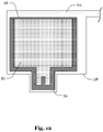
- solution 42 may be heated by heating device 46 until all solvent has evaporated from solution 42 and soluble substance 16 has solidified. Soluble substance 16 may then be milled with mill 48 and sieved with sieve 50 as shown in Fig. 11 . The size of sieve 50 may be 125 ⁇ m. (Milled and sieved) soluble substance 16 may be mixed with water or a saturated (aqueous) solution of the soluble substance 16. After adding one or more of fibers 12, slurry 52 (comprising the mixture and one or more fibers) may be placed into mold 54, as shown in Fig. 12 . If fibers 12 form a textile, mixture and textile layers may be stacked. Mold 54 may have a top portion which is covered by membrane 56.
- Membrane 56 may be solvent-permeable and gas-permeable or solvent-impermeable and gas-permeable. Mold 54 may be placed in gas-impermeable hull 58 and porous structure 60 may connect membrane 56 to a discharge opening in hull 58. If hull 58 is evacuated (to a pressure of about 5 mbar), porous structure 60 may avoid that a gas flow (towards vacuum pump) is obstructed by hull 58. To accelerate evaporation, a temperature of slurry 52 may be maintained at 60 °C. Moreover, a pressure outside hull 58 may be increased (above 1 bar) to accelerate the process and to improve the resistance of core 10 against forces acting on core 10.
- mold 54 may be provided with die 62 that can be urged against slurry 52 to squeeze solvent out of slurry 52 and to make the core which is formed once slurry 52 solidifies around fibers 12, more resistant to forces acting on core 10.
- Die 62 or any other section of mold 54 may be porous to increase a rate at which solvent and vapor are removed from mold 54. Otherwise, solvent and vapor may be removed through the clearance between die 62 and matrix 64.
- mold 54 may comprise two dies 62 to apply the pressure more evenly to the slurry 52. Both dies 62 may be similar and their setup may be the same. Once, soluble substance 16 solidifies around fibers 12, core 10 may be removed from mold 54.
- soluble substance 16 may be heated (to about 700°C at a pressure of about 300MPa, if soluble substance 16 is an alkali salt) and subsequently cooled-down.
- mold 54 may be directly filled with a (dry) powder of soluble substance 16 (without using the steps described in connection with Fig. 12 , Fig. 13 , and Fig. 14 to generate a green body), soluble substance 16 may be melted (e.g., slowly heated in an inert atmosphere, to avoid tool and fiber degradation, such as a nitrogen atmosphere, an argon atmosphere, a vacuum, etc. to about 900°C, if soluble substance 16 is an alkali salt) and subsequently cooled-down.
- core 10 may be removed from mold 54.
- soluble substance 16 maybe injected into mold 54 (at a temperature of more than 800 °C, if soluble substance 16 is an alkali salt) and then cooled down. After having removed core 10 from mold 54, core 10 may be used to manufacture molded article 34 as describe above.
- Fig. 16 shows steps of the process for manufacturing core 10. The process starts at step 66 with providing mold 54 containing soluble substance 16 and one or more fibers 12. The process continues at step 68 with causing soluble substance 16 to solidify around one or more of fibers 12.
Landscapes
- Engineering & Computer Science (AREA)
- Mechanical Engineering (AREA)
- Manufacturing & Machinery (AREA)
- Chemical & Material Sciences (AREA)
- Materials Engineering (AREA)
- Moulding By Coating Moulds (AREA)
- Moulds For Moulding Plastics Or The Like (AREA)
Abstract
Description
- The present disclosure relates to soluble cores. In particular, the present disclosure relates to soluble cores which are reinforced with matter that is insoluble in the solvent of the soluble core.
- Using expendable cores allows for more complex geometries, including internal passages and cavities, that could not be produced when using re-usable (demoldable) cores.
- The present disclosure is directed at a method of manufacturing a core for a production process, a core so manufactured, methods of manufacturing articles in which the core (so manufactured) may be used and systems for manufacturing molded articles in which the methods maybe practiced.
- The method of manufacturing a core for molding comprises providing a mold containing a soluble substance and one or more fibers and causing the soluble substance to solidify around the one or more fibers.
- In this regard, the term "core", as used throughout the description and the claims, particularly refers to a mold insert which may be used to form the internal shape (or features) of a molded article (cast part). The core may be an expendable (or lost) core. I.e., the core maybe destructed when removing the core from the molded article and the core may be designed so that the destruction is not likely to damage the molded article. Destructing the core may be necessary if otherwise withdrawing the core from the molded article would be inhibited by the geometry of the article's internal shape (or features). For example, the expendable core may be placed inside a mold to form internal passages or cavities of the molded article.
- Moreover, the term "core", as used throughout the description and the claims, may also refer to a core which is used for additive manufacturing (e.g., Automated Fiber Placement (AFP), 3-D printing), wrapping, winding and braiding of dry (preform) or pre-impregnated fibers, as a replacement for Ceramic Matrix Composites (CMC) or other ceramic raw materials, or compression molding (of plastics) using Sheet Molding Compound (SMC) or Bulk molding Compound (BMC).
- Moreover, the term "molding", as used throughout the description and the claims, particularly refers to filling a mold with a liquid and causing (or having provided for) conditions under which the liquid begins to solidify. For example, a liquid metal alloy may be injected (under high pressure) into the mold and start to solidify when the temperature of the alloy decreases below a melting temperature. The alloy may comprise aluminum, magnesium, or zinc. Once solidification has sufficiently progressed, the molded article formed by the hardening/hardened alloy may be removed from the mold. In another example, a (reactive) resin maybe injected into the mold in a Resin Transfer Molding (RTM) or injection molding process.
- In this regard, the term "mold", as used throughout the description and the claims, particularly refers to mold parts (for instance, two mold halves) which when put together form a mold cavity, the shape of which defines (at least partially) the external shape of the molded article. The molded article may be removed from the mold by disassembling the mold parts and/or withdrawing the molded article from a mold part to which it adheres. Furthermore, the term "soluble substance", as used throughout the description and the claims, particularly refers to a crystalline substance which can be dissolved in water, alcohols, petrol, aromatic compounds, acetone or aqueous acids/leaches or a mixture of these. The soluble substance may comprise cations and anions. For example, the soluble substance may be a water-soluble substance such as a salt (e.g., an alkali salt) and the one or more fibers may be water insoluble. The soluble substance may also be a water-soluble substance which is mixed with a water-insoluble substance such as sand (as a filler).
- The method may further comprise using the core to produce an article and dissolving the soluble substance in a solvent, wherein the article does not dissolve in the solvent. I.e., the produced article may be resistant to the solvent such that the article is not damaged when the core is removed from the article.
- The production process may be a molding process, an additive manufacturing process, 3D printing, automated fiber placement with in-situ consolidation, automated tape laying, dry or wet filament winding, braiding, or preforming of a composite part or a final part (=article) with the same characteristics of the core.
- The method may further comprise producing an article by using the core in the production process, wherein the core is insoluble in a material of the article.
- Moreover, the term "fiber", as used throughout the description and the claims, particularly refers to a lengthy strand of material. The material may be produced by plants, animals, or geological processes (and modified by a chemical process), or the material may be produced by a physical process (e.g. production of glass fibers), a chemical process, or a combination of both (e.g. application of sizing to glass fibers). For example, the core may be reinforced by one or more abaca fibers, coir fibers, cotton fibers, linen fibers, flax fibers, bamboo fibers, hemp fibers, jute fibers, ramie fibers, sisal fibers, wool fibers, silk fibers, harakeke fibers, alfa fibers, hair, fur, aramid fibers, carbon fibers, glass fibers, ceramic fibers (e.g., silicon carbide fibers, alumina fibers, graphite fibers, etc.), basalt fibers, metal fibers (e.g., iron, steel, tungsten, nickel, titan, aluminum etc.), etc.
- The strand may be of substantially constant thickness and/or cross-sectional shape. The length of the strand may be more than 10, more than 100, or more than 1000 times the thickness of the strand. The one or more fibers may have a length of more than 1 mm, more than 2 mm, more than 3 mm, more than 4 mm, more than 5 mm, more than 6 mm, more than 7 mm, more than 8 mm, more than 9 mm, more than 10 mm, more than 20 mm, more than 30 mm, more than 40 mm, more than 50 mm, more than 75 mm, more than 100 mm, more than 200 mm, more than 300 mm or more than 1000 mm. The fibers may be continuous/endless fibers. A length of one or more of the fibers maybe equal to or exceeding one or more dimensions (e.g., the length, the width and/or the height) of the core. Multiple fibers may be (mechanically, thermally or chemically) interlocked to form a yarn. The fibers (or yarns) may form a textile or roving. For example, the fibers (or yarns) may form a (woven or non-woven) fabric. The core may comprise multiple layers of textile/fabric. The layers may be interlocked (e.g., by stitching).
- The one or more fibers (or yarns) may form a three-dimensional structure (e.g., a mesh or a preform). The three-dimensional structure may comprise tetrahedra, quadrilateral pyramids, triangular prisms, hexahedra, etc. The three-dimensional structure may be formed by 3D-printing. 3D-printing may involve immersing a printing head (nozzle) into an (aqueous) solution comprising the soluble substance and extruding the fiber material into the solution. The material from which the three-dimensional structure is formed may be unevenly distributed throughout the core to (only or particularly) reinforce a part/portion of the core which is expected to experience (relatively) high stress (during molding).
- For example, the three-dimensional structure may reinforce an interlocking connection between the core and the mold. For instance, the three-dimensional structure may be wound around (e.g., in the form of a form a ring, loop or helix) an attachment portion (recess) into which a pin (of the mold) is to be inserted when attaching the core to the mold.
- In addition, the formulation "solidifying around the one or more fibers", as used throughout the description and the claims, particularly refers to a scenario in which the soluble substance forms a matrix in which the one or more fibers are embedded. The soluble substance may adhere to the one or more fibers. If the material of the one or more fibers is porous or allows diffusion of the soluble substance, the soluble substance may extend into pores of the one or more fibers or extend into the fiber material by diffusion. If the core is exposed to stress, a tensile strength of the one or more fibers may prevent the core from breaking. Moreover, the fibers may exhibit a relatively high tensile strength and a relatively low resistance against bending.
- The method may further comprise determining a targeted value of a physical property (e.g., a thermo-mechanical property) of at least a part of the core, wherein the physical property is selected from the group consisting of, a thermal expansion coefficient of the part, a thermal conductivity of the part, a bending strength of the part, a crack sensitivity of the part, a resistance to thermo-shock of the part, and a maximum strain the part is capable of withstanding, and selecting the soluble substance, a material of the one or more fibers, a length of the one or more fibers, and a mass fraction of the material, in accordance with the targeted value.
- For example, the susceptibility of the core to thermal expansion may be decreased (as compared to the susceptibility of the soluble substance to thermal expansion) and the thermal conductivity may be increased (as compared to the thermal conductivity of the soluble substance). Likewise, the bending strength may be increased, the crack sensitivity may be decreased, the resistance to thermo-shock may be increased, and the maximum strain the part is capable of withstanding may be increased.
- This may simplify the formation of an internal shape of a molded article with high accuracy and stability and reduce the time required to heat/cool the core.
- A least one of, the material of the one or more fibers, the length of the one or more fibers, the textile type of the one or more fibers, the orientation/alignment of the one or more fibers and the mass fraction of the material (i.e., the relation between the fiber material and the material mix of which the core is made) may differ between different parts of the core in accordance with differing targeted values of the physical properties of the parts.
- For example, the core may be divided into two or more parts and a part that is expected to experience the highest stress may have longer fibers and/or a higher mass fraction of the material than any other part. If the fibers are unevenly distributed throughout the core, the core may be dividable into two parts that have the same volume but differ substantially (e.g., by more than 5%, more than 10%, more than 25%, more than 50% more than 70%) in regard to a mass fraction of the fiber material in either one of the parts.
- The method may further comprise rating different parts of the core regarding an expected stress-level during molding and arranging the one or more fibers in one or more parts having a relatively high expected stress level along a direction of an internal force that is expected to cause the stress.
- In other words, the fibers may be arranged to counteract a tensile force acting in the core.
- Arranging the fibers within the core may also comprise aligning the fibers.
- The mold may contain solid particles of the soluble substance dispersed in a saturated solution comprising the substance and its solvent.
- For example, the mold may contain a slurry made from salt particles and a (saturated) aqueous solution (e.g., salt dissolved in water). The salt particles may be less than 1 mm, less than 500 µm, less than 250 µm or less than 125 µm in size (thus passing through a 1 mm, a 500 µm, a 250 µm, and a 125 µm sieve, respectively). 40%, 60%, 90%, or 100% of the particles may have a grain size that is smaller than a fiber diameter, in order to provide good filling and a buildup of a fiber-matrix interface in between the fiber(s) and the salt.
- The method may further comprise withdrawing vapor of the solvent from the mold.
- For example, the vapor may be withdrawn through one or more clearances between two or more parts of the mold, or the mold may comprise one or more porous sections which are formed by a gas-permeable and liquid-impermeable, or by a gas-permeable and liquid-permeable porous structure.
- The mold may be heated and/or the aqueous solution may be exposed to a reduced-pressure atmosphere (e.g., by placing the mold in a vacuum) to increase a rate at which the vapor is withdrawn from the mold.
- The mold may be placed in an at least partially flexible gas-impermeable hull (or pouch) which is evacuated. The vapor may be withdrawn through a (woven or nonwoven) fabric (or through another porous gas-permeable structure) connecting the one or more clearances or the one or more porous sections to one or more openings in the at least partially flexible hull through which the vapor is discharged from the at least partially flexible hull. The fabric avoids that the flexible hull blocks or obstructs the path along which the vapor is to be discharged.
- Furthermore, a pressure may be applied to parts of the mold such that the parts are urged towards each other.
- The method may further comprise heating the soluble substance, wherein the soluble substance is caused to solidify around the one or more fibers by cooling the soluble substance.
- The heating may be performed to melt the soluble substance after it has solidified around the one or more fibers due to vapor being withdrawn from the mold or instead of providing for an aqueous solution in the mold and withdrawing vapor from the mold.
- The core comprises a matrix formed by the soluble substance and the one or more fibers embedded in the matrix.
- This allows removing/dissolving the core by the solvent.
- The fiber volume ratio may be above 0.05, 0.1, 0.2 or 0.3.
- The material of the fibers and/or the length of the fibers may differ between different parts of the core.
- The fibers may be unevenly distributed within the core. As describe above, the core may be dividable into two parts that have the same volume, but differ substantially (e.g., by more than 5%, more than 10%, more than 25%, more than 50%, more than 70%) with regard to a mass fraction of the fiber material in either one of the parts.
- The one or more fibers may be concentrated around an attachment portion of the core.
- The method of manufacturing molded articles may comprise providing a mold having the core (made of the fiber-reinforced soluble substance), flowing a material into the mold, and dissolving the soluble substance with the solvent after the material has begun to harden.
- For example, as described above, a liquid metal alloy or plastic melt may be injected (under high pressure) into the mold and start to solidify when the temperature of the alloy/melt decreases below a melting temperature. Once solidification has sufficiently progressed, the molded article formed by the hardening/hardened alloy may be removed from the mold. The core may then be removed from the molded article by dissolving the soluble substance with the solvent, preferably (hot) water or water vapor.
- If the fibers are small compared to an opening in the molded article through which the core material is removed from the core, the fibers may be simply be washed out with the dissolved soluble substance. If the fibers (or yarns) form a textile or multiple layers of textile that are interlocked or if the one or more fibers (or yarns) form a three-dimensional structure that does not fit through the opening, the one or more fibers may be otherwise pushed/pulled out through the opening (e.g., using a rigid element or pressured air).
- The method may further comprise re-using the soluble substance and the fibers for manufacturing one or more further cores.
- For example, the solvent may be withdrawn from the dissolved soluble substance and the crystallized soluble substance may be milled and sieved (as describe above) for reuse.
- The system for manufacturing molded articles may comprise a nozzle, wherein the nozzle is connected to a solvent source and configured to inject solvent into a molded article to dissolve a fiber-reinforced soluble core and a separator, wherein the separator is configured to separate fibers from a solution produced by dissolving the fiber-reinforced soluble core.
- The separator may be a sieve, or, if the fibers are made of a ferro-magnetic material, an electro- or a permanent magnet.
- The system may further comprise an extractor, wherein the extractor is configured to extract a soluble substance from the solution.
- For example, the extractor may heat the solution (e.g. to evaporate the solvent).
- The system may further comprise a mill, wherein the mill is configured to mill the soluble substance.
- The milled soluble substance and the separated fibers may be reused for molding one or more further fiber-reinforced soluble cores.
- The foregoing aspects and many of the attendant advantages will become more readily appreciated as the same becomes better understood by reference to the following description of embodiments, when taken in conjunction with the accompanying drawings, wherein like reference numerals refer to like parts throughout the various views, unless otherwise specified.
-
Fig. 1 schematically illustrates a fiber-reinforced core according to a first example. -
Fig. 2 schematically illustrates a modification of the fiber-reinforced core ofFig. 1 . -
Fig. 3 schematically illustrates a fiber-reinforced core according to a second example. -
Fig. 4 schematically illustrates a modification of the fiber-reinforced core ofFig. 3 . -
Fig. 5 schematically illustrates a fiber-reinforced core according to a third example. -
Fig. 6 schematically illustrates a fiber-reinforced core according to a fourth example. -
Fig. 7 andFig. 8 schematically illustrate the usage of one of the fiber-reinforced cores ofFig. 1 to Fig. 6 in a process of manufacturing a molded article. -
Fig. 9 schematically illustrates removing one of the fiber-reinforced cores ofFig. 1 to -
Fig. 6 from a molded article. -
Fig. 10 schematically illustrates drying the dissolved soluble substance. -
Fig. 11 schematically illustrates milling and sieving the dissolved soluble substance. -
Fig. 12 schematically illustrates a system for manufacturing a fiber-reinforced core for molding according to a first example. -
Fig. 13 schematically illustrates a system for manufacturing a fiber-reinforced core for molding according to a second example. -
Fig. 14 schematically illustrates a system for manufacturing a fiber-reinforced core for molding according to a third example. -
Fig. 15 schematically illustrates a system for manufacturing a fiber-reinforced core for molding according to a fourth example. -
Fig. 16 shows steps of a process for manufacturing a fiber-reinforced core. - Notably, the drawings are not drawn to scale and unless otherwise indicated, they are merely intended to conceptually illustrate the structures and procedures described herein.
-
Fig. 1 showscore 10 which is reinforced byfibers 12.Fibers 12 may have a length of more than 1 mm.Fibers 12 are embedded inmatrix 14 which is formed by soluble substance 16 (e.g., a water-soluble alkali salt) that has solidified (crystallized) aroundfibers 12. The fiber material and the mass fraction of the fiber material may be determined based on a targeted strength, a targeted thermal expansion coefficient, and a targeted thermal conductivity ofcore 10. To this end, the selected fiber material may exhibit a substantially lower thermal expansion coefficient thansoluble substance 16, and a substantially higher thermal conductivity thansoluble substance 16. For example, the selected fiber material may exhibit a thermal expansion coefficient which is (at room temperature) 10% lower than a thermal expansion coefficient ofsoluble substance 16, and a thermal conductivity which is (at room temperature) 10% higher than a thermal conductivity ofsoluble substance 16. The mass fraction may be between 0.01 and 0.7 and preferably between 0.1 and 0.5. -
Core 10 comprisesattachment portion 18 for attachingcore 10 to a mold (as will be discussed in more detail further below with regard toFig. 7 ).Attachment portion 18 hasrecess 20, into which a pin of the mold can be inserted. Althoughcore 10 is shown with only oneattachment portion 18,core 10 may comprise multiple attachment portions 18 (e.g.,attachment portions 18 at opposite sides of core 10). Moreover,attachment portion 18 may be modified in various ways including having a cubical shape as opposed to the cylindrical shape shown in the example. Likewise, the shape ofcore 10 may be modified depending on the internal shape or features of the article to be molded. For example,core 10 may not have a cylindrical shape as shown inFig. 1 but a cubical shape, a shape of a bent tube, or any other shape. - As shown in
Fig. 2 ,fibers 12 may be unevenly distributed withincore 10 as opposed to being evenly distributed withincore 10, as inFig. 1 . The uneven distribution may serve to particularly increase a strength of a part or portion ofcore 10 which is expected to experience relatively high stress during molding. As illustrated inFig. 2 ,attachment portion 18 may be particularly strengthened. The uneven distribution may also serve to particularly increase a strength of a part or portion which would otherwise be substantially weaker than other parts or portions ofcore 10. The uneven distribution may further serve to improve a heat transport throughoutcore 10. For example, a relatively thin part or portion ofcore 10 may comprise relativelymore fibers 12 than a relatively thick part or portion ofcore 10, to avoid that the relatively thin part or portion breaks during molding and/or to avoid that the relatively thin part or portion becomes a bottle neck with regard to heat transport. This may also serve to reduce tension incore 10 caused by an uneven temperature distribution during molding. - As shown in
Fig. 3 ,fibers 12 may be aligned. For example, an orientation offibers 12 that are relatively close to each other may be nearly parallel, whereas an orientation offibers 12 which are relatively far from each other may not. The alignment offibers 12 maybe beneficial if forces acting oncore 12 during molding can be countered by the tensile strength offibers 12. In other words, the alignment offibers 12 may cause a longitudinal axis offiber 12 to be perpendicular to a crack that would otherwise occur iffiber 12 would not counteract the (tensile) forces causing the crack. - As shown in
Fig. 4 ,fibers 12 may be unevenly distributed withincore 10 as opposed to being evenly distributed withincore 10, as inFig. 3 , irrespective of the fact that some or all offibers 12 may be aligned. An uneven distribution may be achieved by avoiding a migration offibers 12 between different core 12 segments (e.g., due to viscosity) or segmentingcore 10 using one or more fiber-impermeable barriers. As shown inFig. 5 , an uneven distribution may also be achieved by connectingfibers 12 to form one or more yarns and/or connecting fibers 12 (or the yarns) to form three-dimensional structure 22. Notably, three-dimensional structure 22 may also be formed by a single fiber or filament. For example, three-dimensional structure 22 may be 3D-printed and integrated intocore 10. As shown inFig. 6 ,core 10 may also comprise only asingle fiber 12 or filament that particularly reinforces a portion ofcore 12. For instance,single fiber 12 may be wound or braided aroundattachment portion 18 to particularly increase its strength. - As shown in
Fig. 7 andFig. 8 ,core 10 may be attached topart 24 ofmold 26. To this end,part 24 comprises protrudingportion 28 that fits intorecess 20 ofattachment portion 18. After assemblingmold 26,material 30 may be flown or injected throughpart 32 intomold 26. Aftermaterial 30 has hardened,mold 26 may be disassembled and moldedarticle 34 may be removed frompart 24 by pushing moldedarticle 34 out ofpart 24 usingrod 36.Rod 36 may be pushed againstcore 10 to avoid damage to moldedarticle 34. After moldedarticle 34 is removed frompart 24, water-soluble substance 16 ofcore 10 may be dissolved with water as schematically illustrated inFig. 9 . As shown inFig. 9 , water or steam may be flown throughnozzle 38 into opening 40 of moldedarticle 34 andsoluble substance 16 may be washed out of moldedarticle 34.Fibers 12 may be removed fromsolution 42 bysieve 44, for reuse or disposal. - As shown in
Fig. 10 ,solution 42 may be heated byheating device 46 until all solvent has evaporated fromsolution 42 andsoluble substance 16 has solidified.Soluble substance 16 may then be milled withmill 48 and sieved withsieve 50 as shown inFig. 11 . The size ofsieve 50 may be 125 µm. (Milled and sieved)soluble substance 16 may be mixed with water or a saturated (aqueous) solution of thesoluble substance 16. After adding one or more offibers 12, slurry 52 (comprising the mixture and one or more fibers) may be placed intomold 54, as shown inFig. 12 . Iffibers 12 form a textile, mixture and textile layers may be stacked.Mold 54 may have a top portion which is covered bymembrane 56.Membrane 56 may be solvent-permeable and gas-permeable or solvent-impermeable and gas-permeable.Mold 54 may be placed in gas-impermeable hull 58 andporous structure 60 may connectmembrane 56 to a discharge opening inhull 58. Ifhull 58 is evacuated (to a pressure of about 5 mbar),porous structure 60 may avoid that a gas flow (towards vacuum pump) is obstructed byhull 58. To accelerate evaporation, a temperature ofslurry 52 may be maintained at 60 °C. Moreover, a pressure outsidehull 58 may be increased (above 1 bar) to accelerate the process and to improve the resistance ofcore 10 against forces acting oncore 10. - As shown in
Fig. 13 ,mold 54 may be provided with die 62 that can be urged againstslurry 52 to squeeze solvent out ofslurry 52 and to make the core which is formed onceslurry 52 solidifies aroundfibers 12, more resistant to forces acting oncore 10.Die 62 or any other section ofmold 54 may be porous to increase a rate at which solvent and vapor are removed frommold 54. Otherwise, solvent and vapor may be removed through the clearance betweendie 62 andmatrix 64. As shown inFig. 14 ,mold 54 may comprise two dies 62 to apply the pressure more evenly to theslurry 52. Both dies 62 may be similar and their setup may be the same. Once,soluble substance 16 solidifies aroundfibers 12,core 10 may be removed frommold 54. - Or, as shown in
Fig. 15 ,soluble substance 16 may be heated (to about 700°C at a pressure of about 300MPa, ifsoluble substance 16 is an alkali salt) and subsequently cooled-down. Otherwise,mold 54 may be directly filled with a (dry) powder of soluble substance 16 (without using the steps described in connection withFig. 12 ,Fig. 13 , andFig. 14 to generate a green body),soluble substance 16 may be melted (e.g., slowly heated in an inert atmosphere, to avoid tool and fiber degradation, such as a nitrogen atmosphere, an argon atmosphere, a vacuum, etc. to about 900°C, ifsoluble substance 16 is an alkali salt) and subsequently cooled-down. Oncesoluble substance 16 solidifies aroundfibers 12,core 10 may be removed frommold 54. In another example,soluble substance 16 maybe injected into mold 54 (at a temperature of more than 800 °C, ifsoluble substance 16 is an alkali salt) and then cooled down. After having removedcore 10 frommold 54,core 10 may be used to manufacture moldedarticle 34 as describe above. -
Fig. 16 shows steps of the process for manufacturingcore 10. The process starts atstep 66 with providingmold 54 containingsoluble substance 16 and one ormore fibers 12. The process continues atstep 68 with causingsoluble substance 16 to solidify around one or more offibers 12. -
- 10
- core
- 12
- fibers
- 14
- matrix
- 16
- soluble substance
- 18
- attachment portion
- 20
- recess
- 22
- three-dimensional structure
- 24
- part (bottom of mold)
- 26
- mold
- 28
- protruding portion
- 30
- material
- 32
- part (top of mold)
- 34
- molded article
- 36
- rod
- 38
- nozzle
- 40
- opening
- 42
- solution
- 44
- sieve
- 46
- heating device
- 48
- mill
- 50
- sieve
- 52
- slurry
- 54
- mold
- 56
- membrane
- 58
- pouch
- 60
- porous structure
- 62
- die
- 64
- matrix
- 66
- step
- 68
- step
Claims (15)
- A method of manufacturing a core (10) for a production process, comprising:providing (22) a mold (54) containing a soluble substance (16) and one or more fibers (12); andcausing the soluble substance (16) to solidify around the one or more fibers (12).
- The method of manufacturing a core (10) of claim 1,
wherein the soluble substance (16) is a salt or another water-soluble substance and the one or more fibers (12) are water insoluble; or
wherein the soluble substance (16) is soluble by a solvent selected from the group consisting of water, alcohols, petrol, aromatic compounds, acetone or aqueous acids/leaches or a mixture of these and the one or more fibers (12) are insoluble in the solvent. - The method of manufacturing a core (10) of claim 1 or 2, further comprising:using the core (10) to produce an article; anddissolving the soluble substance (16) in a solvent;wherein the article does not dissolve in the solvent.
- The method of manufacturing a core (10) of any one of claims 1 to 3,
wherein the production process is a molding process, an additive manufacturing process, 3D printing, automated fiber placement with in-situ consolidation, automated tape laying, dry or wet filament winding, braiding, or preforming of a composite part; and/or
wherein the method further comprises producing an article by using the core in the production process, wherein the core is insoluble in a material of the article. - The method of manufacturing a core (10) of any one of claims 1 to 4,
wherein the one or more fibers (12) have a length of more than 1 mm, more than 2 mm, more than 3 mm, more than 4 mm, more than 5 mm, more than 6 mm, more than 7 mm, more than 8 mm, more than 9 mm, more than 10 mm, more than 20 mm, more than 30 mm, more than 40 mm, more than 50 mm, more than 60 mm, more than 70 mm, more than 80 mm, more than 90 mm, more than 100 mm, more than 200 mm, more than 300 mm or more than 1000 mm; and/or
wherein the one or more fibers (12) form a textile or roving. - The method of manufacturing a core (10) of any one of claims 1 to 5, further comprising:determining a targeted value of a physical property of at least a part of the core (10), wherein the physical property is selected from the group consisting of a thermal expansion coefficient of the part, a thermal conductivity of the part, a bending strength of the part, a crack sensitivity of the part, a resistance to thermo-shock of the part and a maximum strain the part is capable of withstanding; andselecting the soluble substance (16), a material of the one or more fibers (12), a length of the one or more fibers (12) and a mass fraction of the material in accordance with the targeted value.
- The method of manufacturing a core (10) of claim 6, wherein a least one of, the material of the one or more fibers (12), the length of the one or more fibers (12) and the mass fraction of the material differ between different parts of the core (10) in accordance with differing targeted values of the physical properties of the parts.
- The method of manufacturing a core (10) of any one of claims 1 to 7, wherein the mold (54) contains solid particles of the soluble substance (16) dispersed in a saturated solution comprising the substance and its solvent.
- The method of manufacturing a core (10) of any one of claims 1 to 8, further comprising:withdrawing vapor from the mold (54) through a gas-permeable and/or liquid-permeable porous structure (56, 60); and/orexposing the saturated solution to a reduced-pressure atmosphere.
- The method of manufacturing a core (10) of any one of claims 1 to 9, further comprising:heating the soluble substance (16);wherein the soluble substance (16) is caused to solidify around the one or more fibers (12) by cooling the soluble substance (16).
- The method of manufacturing a core (10) of any one of claims 1 to 10, wherein the one or more fibers (12) are selected from the group consisting of aramid fibers, carbon fibers, glass fibers, ceramic fibers, basalt fibers, natural fibers and metal fibers.
- A core (10), comprising:a matrix (14) formed by a soluble substance (16); andone or more fibers (12) embedded in the matrix (14).
- The core (10) of claim 12,
wherein the one or more fibers (12) have a length of more than 1 mm, more than 2 mm, more than 3 mm, more than 4 mm, more than 5 mm, more than 6 mm, more than 7 mm, more than 8 mm, more than 9 mm, more than 10 mm, more than 20 mm, more than 30 mm, more than 40 mm, more than 50 mm, more than 60 mm, more than 70 mm, more than 80 mm, more than 90 mm, more than 100 mm, more than 200 mm, more than 300 mm or more than 1000 mm; and/or.
wherein a fiber volume ratio is above 0.05, 0.1, 0.2, or 0.3. - The core (10) of claim 12 or 13,
wherein at least one of, a material of the one or more fibers (12) and a length of the one or more fibers (12), differ between different parts of the core (10); and/or
wherein the one or more fibers (12) are unevenly distributed within the core (10). - The core (10) of claim 14, further comprising:
an attachment portion (18), wherein the one or more fibers (12) are concentrated around the attachment portion (18).
Priority Applications (2)
| Application Number | Priority Date | Filing Date | Title |
|---|---|---|---|
| EP20201634.1A EP3984715B1 (en) | 2020-10-13 | 2020-10-13 | Fiber-reinforced soluble core and method for its manufacture |
| US17/471,461 US20220111563A1 (en) | 2020-10-13 | 2021-09-10 | Fiber-Reinforced Soluble Core |
Applications Claiming Priority (1)
| Application Number | Priority Date | Filing Date | Title |
|---|---|---|---|
| EP20201634.1A EP3984715B1 (en) | 2020-10-13 | 2020-10-13 | Fiber-reinforced soluble core and method for its manufacture |
Publications (3)
| Publication Number | Publication Date |
|---|---|
| EP3984715A1 true EP3984715A1 (en) | 2022-04-20 |
| EP3984715C0 EP3984715C0 (en) | 2023-11-15 |
| EP3984715B1 EP3984715B1 (en) | 2023-11-15 |
Family
ID=72852520
Family Applications (1)
| Application Number | Title | Priority Date | Filing Date |
|---|---|---|---|
| EP20201634.1A Active EP3984715B1 (en) | 2020-10-13 | 2020-10-13 | Fiber-reinforced soluble core and method for its manufacture |
Country Status (2)
| Country | Link |
|---|---|
| US (1) | US20220111563A1 (en) |
| EP (1) | EP3984715B1 (en) |
Citations (5)
| Publication number | Priority date | Publication date | Assignee | Title |
|---|---|---|---|---|
| WO1993025365A1 (en) * | 1992-06-11 | 1993-12-23 | Harri Sahari | Procedure in association with production of plastic pieces |
| JPH07316379A (en) * | 1994-05-23 | 1995-12-05 | Nippon Synthetic Chem Ind Co Ltd:The | Resin composition for cores and production of blow molded articles using the same |
| CN106182645A (en) * | 2016-08-08 | 2016-12-07 | 厦门建霖工业有限公司 | A kind of abnormity hollow crosses water assembly solubility insert molding method |
| CN106751450A (en) * | 2016-11-10 | 2017-05-31 | 山东非金属材料研究所 | A kind of water-soluble core material |
| WO2020127980A1 (en) * | 2018-12-20 | 2020-06-25 | Proionic Gmbh | Mold composition comprising a sugar component |
Family Cites Families (18)
| Publication number | Priority date | Publication date | Assignee | Title |
|---|---|---|---|---|
| GB1412983A (en) * | 1971-11-30 | 1975-11-05 | Debell & Richardson | Method of producing porous plastic materials |
| US4199864A (en) * | 1975-12-22 | 1980-04-29 | Arthur Ashman | Endosseous plastic implant method |
| US4383956A (en) * | 1981-01-30 | 1983-05-17 | American Optical Corporation | Method of a single element complete air filtering structure for a respirator filter cartridge |
| US4962003A (en) * | 1988-04-27 | 1990-10-09 | Lhymn Yoon O | Development of fusible alloy composites |
| JPH0976266A (en) * | 1995-09-12 | 1997-03-25 | Honda Motor Co Ltd | Preparation of laminated body |
| TW476697B (en) * | 1997-11-26 | 2002-02-21 | Idemitsu Petrochemical Co | Fiber-reinforced resin molded article and method of manufacturing the same |
| FR2776264B1 (en) * | 1998-03-23 | 2000-06-02 | Eurocopter France | PAD WITH VARIABLE PIT IN COMPOSITE MATERIAL FOR A HELICOPTER ROTOR AND METHOD FOR MANUFACTURING SUCH A PAD |
| US20020135161A1 (en) * | 2001-03-26 | 2002-09-26 | Lamb Tony M. | Glass fiber reinforced thermoplastic components |
| US6776942B2 (en) * | 2001-11-20 | 2004-08-17 | Taylor Made Golf Company, Inc. | Mold for making golf balls and methods for using it |
| US7445735B2 (en) * | 2004-12-07 | 2008-11-04 | Daramic Llc | Method of making microporous material |
| DE102006031336B4 (en) * | 2006-07-06 | 2010-08-05 | Airbus Deutschland Gmbh | Method for producing a fiber composite component in the aerospace industry |
| US11179243B2 (en) * | 2007-02-28 | 2021-11-23 | Happe Spine Llc | Implantable devices |
| WO2008106625A2 (en) * | 2007-02-28 | 2008-09-04 | University Of Notre Dame Du Lac | Porous composite biomaterials and related methods |
| WO2012172982A1 (en) * | 2011-06-16 | 2012-12-20 | 東レ株式会社 | Method for manufacturing fiber-reinforced plastic |
| US9504550B2 (en) * | 2014-06-26 | 2016-11-29 | Vertera, Inc. | Porous devices and processes for producing same |
| US9085665B1 (en) * | 2014-12-31 | 2015-07-21 | Vertera, Inc. | Method for producing porous material |
| US10300631B2 (en) * | 2015-11-30 | 2019-05-28 | Honeywell International Inc. | Carbon fiber preforms |
| WO2022056384A1 (en) * | 2020-09-11 | 2022-03-17 | Happe Spine Llc | Method for forming an implantable medical device with varied composition and porosity |
-
2020
- 2020-10-13 EP EP20201634.1A patent/EP3984715B1/en active Active
-
2021
- 2021-09-10 US US17/471,461 patent/US20220111563A1/en active Pending
Patent Citations (5)
| Publication number | Priority date | Publication date | Assignee | Title |
|---|---|---|---|---|
| WO1993025365A1 (en) * | 1992-06-11 | 1993-12-23 | Harri Sahari | Procedure in association with production of plastic pieces |
| JPH07316379A (en) * | 1994-05-23 | 1995-12-05 | Nippon Synthetic Chem Ind Co Ltd:The | Resin composition for cores and production of blow molded articles using the same |
| CN106182645A (en) * | 2016-08-08 | 2016-12-07 | 厦门建霖工业有限公司 | A kind of abnormity hollow crosses water assembly solubility insert molding method |
| CN106751450A (en) * | 2016-11-10 | 2017-05-31 | 山东非金属材料研究所 | A kind of water-soluble core material |
| WO2020127980A1 (en) * | 2018-12-20 | 2020-06-25 | Proionic Gmbh | Mold composition comprising a sugar component |
Also Published As
| Publication number | Publication date |
|---|---|
| EP3984715C0 (en) | 2023-11-15 |
| US20220111563A1 (en) | 2022-04-14 |
| EP3984715B1 (en) | 2023-11-15 |
Similar Documents
| Publication | Publication Date | Title |
|---|---|---|
| CN104105848B (en) | Gas turbine fan is compound accommodates shell and preparation method | |
| CN106891549B (en) | A kind of preparation facilities of MULTILAYER COMPOSITE eccentric abrasion prevention coiled rod | |
| JP5901518B2 (en) | Manufacturing method for advanced composite components | |
| CA3106168C (en) | Methods and compositions for compression molding | |
| JP2011504823A (en) | Method for producing fiber composite hollow body with fiber orientation optimized for force transmission and stress | |
| US20140178653A1 (en) | Production Method for Composite Shaped Product Having Undercut Portion | |
| JP6016428B2 (en) | A bundle of roving yarn, a method of producing a bundle of roving yarn, and a method of producing a workpiece | |
| CN102069149A (en) | Fiber and sand core reinforced thereby | |
| KR102349727B1 (en) | 3-dimensional high-strength fiber composite component and method for producing same | |
| CN107325481A (en) | A kind of phenoplasts inspection shaft well lid and preparation method thereof | |
| EP3984715B1 (en) | Fiber-reinforced soluble core and method for its manufacture | |
| JP2020028984A (en) | Ud-like closed fiber-reinforced composite molded product by filament winding (fw) method and method for producing the same | |
| CN114072273A (en) | Rotating component made of composite material with improved delamination resistance | |
| Dong et al. | Fabrication of a continuous carbon fiber-reinforced phenolic resin composites via in situ-curing 3D printing technology | |
| US20160176124A1 (en) | Method of injection molding a part made of composite material with prior pre-consolidation of the fiber preform | |
| CN102235057B (en) | A kind of FRP muscle | |
| JP6526495B2 (en) | Method of manufacturing pipe molded article | |
| US11548232B2 (en) | Method of manufacturing isotropic parts utilizing additive manufacturing methods | |
| CN108864995A (en) | A kind of polyaxial composite bend and preparation method | |
| CN113085084B (en) | Continuous fiber reinforced thermoplastic resin composite material and preparation method thereof | |
| CN109049759A (en) | Composite material wheel hub and its manufacturing method | |
| JP5598931B2 (en) | Fiber reinforced resin substrate, method for producing resin molded body, and resin processing machine for implementing the method | |
| CN111844523B (en) | Method for sizing pre-impregnated fiber bundles for three-dimensional weaving by adopting thermoplastic resin | |
| CN115583055A (en) | Process for producing fiber-reinforced composite material and fiber-reinforced composite material | |
| JP2019155730A (en) | Manufacturing method of UD-like fiber reinforced composite sheet by filament winding (FW) method |
Legal Events
| Date | Code | Title | Description |
|---|---|---|---|
| PUAI | Public reference made under article 153(3) epc to a published international application that has entered the european phase |
Free format text: ORIGINAL CODE: 0009012 |
|
| STAA | Information on the status of an ep patent application or granted ep patent |
Free format text: STATUS: THE APPLICATION HAS BEEN PUBLISHED |
|
| AK | Designated contracting states |
Kind code of ref document: A1 Designated state(s): AL AT BE BG CH CY CZ DE DK EE ES FI FR GB GR HR HU IE IS IT LI LT LU LV MC MK MT NL NO PL PT RO RS SE SI SK SM TR |
|
| STAA | Information on the status of an ep patent application or granted ep patent |
Free format text: STATUS: REQUEST FOR EXAMINATION WAS MADE |
|
| 17P | Request for examination filed |
Effective date: 20221020 |
|
| RBV | Designated contracting states (corrected) |
Designated state(s): AL AT BE BG CH CY CZ DE DK EE ES FI FR GB GR HR HU IE IS IT LI LT LU LV MC MK MT NL NO PL PT RO RS SE SI SK SM TR |
|
| GRAP | Despatch of communication of intention to grant a patent |
Free format text: ORIGINAL CODE: EPIDOSNIGR1 |
|
| STAA | Information on the status of an ep patent application or granted ep patent |
Free format text: STATUS: GRANT OF PATENT IS INTENDED |
|
| INTG | Intention to grant announced |
Effective date: 20230517 |
|
| GRAS | Grant fee paid |
Free format text: ORIGINAL CODE: EPIDOSNIGR3 |
|
| GRAA | (expected) grant |
Free format text: ORIGINAL CODE: 0009210 |
|
| STAA | Information on the status of an ep patent application or granted ep patent |
Free format text: STATUS: THE PATENT HAS BEEN GRANTED |
|
| AK | Designated contracting states |
Kind code of ref document: B1 Designated state(s): AL AT BE BG CH CY CZ DE DK EE ES FI FR GB GR HR HU IE IS IT LI LT LU LV MC MK MT NL NO PL PT RO RS SE SI SK SM TR |
|
| REG | Reference to a national code |
Ref country code: CH Ref legal event code: EP Ref country code: GB Ref legal event code: FG4D |
|
| REG | Reference to a national code |
Ref country code: DE Ref legal event code: R096 Ref document number: 602020021009 Country of ref document: DE |
|
| REG | Reference to a national code |
Ref country code: IE Ref legal event code: FG4D |
|
| U01 | Request for unitary effect filed |
Effective date: 20231115 |
|
| U07 | Unitary effect registered |
Designated state(s): AT BE BG DE DK EE FI FR IT LT LU LV MT NL PT SE SI Effective date: 20231121 |
|
| PG25 | Lapsed in a contracting state [announced via postgrant information from national office to epo] |
Ref country code: GR Free format text: LAPSE BECAUSE OF FAILURE TO SUBMIT A TRANSLATION OF THE DESCRIPTION OR TO PAY THE FEE WITHIN THE PRESCRIBED TIME-LIMIT Effective date: 20240216 |
|
| PG25 | Lapsed in a contracting state [announced via postgrant information from national office to epo] |
Ref country code: IS Free format text: LAPSE BECAUSE OF FAILURE TO SUBMIT A TRANSLATION OF THE DESCRIPTION OR TO PAY THE FEE WITHIN THE PRESCRIBED TIME-LIMIT Effective date: 20240315 |
|
| PG25 | Lapsed in a contracting state [announced via postgrant information from national office to epo] |
Ref country code: ES Free format text: LAPSE BECAUSE OF FAILURE TO SUBMIT A TRANSLATION OF THE DESCRIPTION OR TO PAY THE FEE WITHIN THE PRESCRIBED TIME-LIMIT Effective date: 20231115 |
|
| PG25 | Lapsed in a contracting state [announced via postgrant information from national office to epo] |
Ref country code: IS Free format text: LAPSE BECAUSE OF FAILURE TO SUBMIT A TRANSLATION OF THE DESCRIPTION OR TO PAY THE FEE WITHIN THE PRESCRIBED TIME-LIMIT Effective date: 20240315 Ref country code: GR Free format text: LAPSE BECAUSE OF FAILURE TO SUBMIT A TRANSLATION OF THE DESCRIPTION OR TO PAY THE FEE WITHIN THE PRESCRIBED TIME-LIMIT Effective date: 20240216 Ref country code: ES Free format text: LAPSE BECAUSE OF FAILURE TO SUBMIT A TRANSLATION OF THE DESCRIPTION OR TO PAY THE FEE WITHIN THE PRESCRIBED TIME-LIMIT Effective date: 20231115 |