EP3984699B1 - Tragbares werkzeug für spreizdübel - Google Patents
Tragbares werkzeug für spreizdübel Download PDFInfo
- Publication number
- EP3984699B1 EP3984699B1 EP21200937.7A EP21200937A EP3984699B1 EP 3984699 B1 EP3984699 B1 EP 3984699B1 EP 21200937 A EP21200937 A EP 21200937A EP 3984699 B1 EP3984699 B1 EP 3984699B1
- Authority
- EP
- European Patent Office
- Prior art keywords
- screw
- barrel
- slider
- motor
- support
- Prior art date
- Legal status (The legal status is an assumption and is not a legal conclusion. Google has not performed a legal analysis and makes no representation as to the accuracy of the status listed.)
- Active
Links
- 230000000295 complement effect Effects 0.000 claims description 9
- 230000005540 biological transmission Effects 0.000 claims description 8
- 239000003638 chemical reducing agent Substances 0.000 claims description 7
- 230000008878 coupling Effects 0.000 claims description 6
- 238000010168 coupling process Methods 0.000 claims description 6
- 238000005859 coupling reaction Methods 0.000 claims description 6
- 239000012636 effector Substances 0.000 claims description 4
- 238000003780 insertion Methods 0.000 claims description 3
- 230000037431 insertion Effects 0.000 claims description 3
- 238000007373 indentation Methods 0.000 claims 7
- 238000012544 monitoring process Methods 0.000 claims 7
- 238000005096 rolling process Methods 0.000 claims 1
- 210000003423 ankle Anatomy 0.000 description 22
- 238000009434 installation Methods 0.000 description 5
- SHXWCVYOXRDMCX-UHFFFAOYSA-N 3,4-methylenedioxymethamphetamine Chemical compound CNC(C)CC1=CC=C2OCOC2=C1 SHXWCVYOXRDMCX-UHFFFAOYSA-N 0.000 description 3
- 241000110847 Kochia Species 0.000 description 3
- 230000000903 blocking effect Effects 0.000 description 3
- 208000023178 Musculoskeletal disease Diseases 0.000 description 2
- 230000008030 elimination Effects 0.000 description 2
- 238000003379 elimination reaction Methods 0.000 description 2
- 238000005452 bending Methods 0.000 description 1
- 210000000078 claw Anatomy 0.000 description 1
- 230000007547 defect Effects 0.000 description 1
- 238000010586 diagram Methods 0.000 description 1
- 238000000605 extraction Methods 0.000 description 1
- 238000000034 method Methods 0.000 description 1
- 230000000750 progressive effect Effects 0.000 description 1
- 230000003252 repetitive effect Effects 0.000 description 1
- 230000000284 resting effect Effects 0.000 description 1
- 230000001629 suppression Effects 0.000 description 1
Images

Classifications
-
- B—PERFORMING OPERATIONS; TRANSPORTING
- B25—HAND TOOLS; PORTABLE POWER-DRIVEN TOOLS; MANIPULATORS
- B25B—TOOLS OR BENCH DEVICES NOT OTHERWISE PROVIDED FOR, FOR FASTENING, CONNECTING, DISENGAGING OR HOLDING
- B25B27/00—Hand tools, specially adapted for fitting together or separating parts or objects whether or not involving some deformation, not otherwise provided for
- B25B27/0007—Tools for fixing internally screw-threaded tubular fasteners
- B25B27/0014—Tools for fixing internally screw-threaded tubular fasteners motor-driven
-
- B—PERFORMING OPERATIONS; TRANSPORTING
- B25—HAND TOOLS; PORTABLE POWER-DRIVEN TOOLS; MANIPULATORS
- B25B—TOOLS OR BENCH DEVICES NOT OTHERWISE PROVIDED FOR, FOR FASTENING, CONNECTING, DISENGAGING OR HOLDING
- B25B31/00—Hand tools for applying fasteners
-
- B—PERFORMING OPERATIONS; TRANSPORTING
- B25—HAND TOOLS; PORTABLE POWER-DRIVEN TOOLS; MANIPULATORS
- B25B—TOOLS OR BENCH DEVICES NOT OTHERWISE PROVIDED FOR, FOR FASTENING, CONNECTING, DISENGAGING OR HOLDING
- B25B21/00—Portable power-driven screw or nut setting or loosening tools; Attachments for drilling apparatus serving the same purpose
- B25B21/007—Attachments for drilling apparatus for screw or nut setting or loosening
-
- B—PERFORMING OPERATIONS; TRANSPORTING
- B25—HAND TOOLS; PORTABLE POWER-DRIVEN TOOLS; MANIPULATORS
- B25F—COMBINATION OR MULTI-PURPOSE TOOLS NOT OTHERWISE PROVIDED FOR; DETAILS OR COMPONENTS OF PORTABLE POWER-DRIVEN TOOLS NOT PARTICULARLY RELATED TO THE OPERATIONS PERFORMED AND NOT OTHERWISE PROVIDED FOR
- B25F5/00—Details or components of portable power-driven tools not particularly related to the operations performed and not otherwise provided for
- B25F5/001—Gearings, speed selectors, clutches or the like specially adapted for rotary tools
-
- B—PERFORMING OPERATIONS; TRANSPORTING
- B25—HAND TOOLS; PORTABLE POWER-DRIVEN TOOLS; MANIPULATORS
- B25F—COMBINATION OR MULTI-PURPOSE TOOLS NOT OTHERWISE PROVIDED FOR; DETAILS OR COMPONENTS OF PORTABLE POWER-DRIVEN TOOLS NOT PARTICULARLY RELATED TO THE OPERATIONS PERFORMED AND NOT OTHERWISE PROVIDED FOR
- B25F5/00—Details or components of portable power-driven tools not particularly related to the operations performed and not otherwise provided for
- B25F5/02—Construction of casings, bodies or handles
Definitions
- the present disclosure relates to a portable tool configured to ensure the expansion of a dowel (of a screw and dowel assembly).
- HWA Hollow Wall Anchor
- Molly anchor typically metallic
- the expansion of the anchor is not allowed by screwing the screw, but requires a specific tool, namely an expansion control pliers well known in the state of the art.
- the clamp mechanism thus has two parts, movable relative to each other, namely a fixed part and a slide pressing respectively against a shoulder of the ankle and the head of the screw, and allowing the spacing of the screw head relative to the shoulder of the dowel when moving the slide, to cause expansion of the dowel.
- the pliers conventionally comprise a handle, with a fixed branch and a movable branch, which when driven towards the fixed branch, makes it possible to cause the movement of the slide by a given pitch, and thus to separate the head of the screw from the ankle shoulder.
- the stroke required for expansion of the ankle is not a fixed value and depends on the model of the ankle: with such a clamp, optimal expansion of the ankle may require several presses on the handle to cause several consecutive movements of the ankle. slide (from the given pitch) to the desired stroke.
- Some expansion control pliers include an adjustment system that allows you to control the stroke, by controlling the number of presses on the handle and therefore the number of steps.
- this type of pliers however has the disadvantage of requiring a large number of presses on the handle to install the dowels, which can lead to musculoskeletal disorders for the operators.
- the expansion control pliers on the market have insufficient slide travel to ensure optimal expansion of the dowel, even with several successive presses on the handle.
- expansion of the ankle may require a two-stage installation procedure, i.e., first using the pliers to move the screw head away from the shoulder of the ankle while performing an initial expansion , but only partial of the ankle.
- the operator disengages the clamp from the dowel, to proceed to screwing the screw, and thus bringing the head of the screw closer to the shoulder of the dowel, before re-engaging the expansion control pliers to ensure the desired expansion during a second use of the pliers.
- This disclosure improves the situation.
- the user interface is a rotary adjustment wheel.
- the adjustment wheel can be integral with the rotary axis of a potentiometer, the control module comprising the motor card connected to the terminals of the potentiometer and associating different values of the variable resistor at the terminals of the potentiometer with different values of the stroke determined.
- the value of the stroke is adjustable over a range which extends to at least 44 mm for the value of the determined stroke.
- said user interface ensures the adjustment of the value of the stroke determined according to an adjustment increment less than or equal to 3 mm, preferably less than or equal to 2 mm, or even less than or equal to 1 mm.
- the transmission between the rotor of the electric motor comprises a screw/nut system, configured to transform the rotational movement of the motor rotor into a translational movement of the slide.
- the tip comprises a barrel terminated at its distal end by the first support, and connected at its proximal end to a body of the tool, said body carrying the motor, or even a reduction gear as well as the module of control, and in which the tubular barrel comprises a housing forming a slide for the slide, with blocking the rotation of the slide relative to the barrel around a longitudinal axis of the barrel.
- the screw of the screw-nut system extends internally to the barrel, guided in rotation by a bearing such as a bearing, connecting the screw and the wall internal of the barrel, and said nut is mounted movable in translation inside the housing, without the possibility of rotation of the nut relative to the barrel around a longitudinal axis of the barrel.
- the tip and the body of the tool comprise removable fixing means between the proximal end of the barrel and the body of the tool, comprising for example a retaining ring and in which the end of the screw at the proximal end of the barrel, on the one hand, and the output of the reducer from the body of the tool, on the other hand, comprise complementary coupling parts by interlocking, removable ensuring torque transmission .
- the user interface is located on the rear part of the body of the tool, diametrically opposite to the tip connected to the front part of the body of the tool.
- the tool comprises a handle, and in which said control member is a trigger configured to be pressed by a finger such as the index finger of the hand gripping the handle.
- the energy source of the motor and the control module is a battery, possibly provided removable relative to the body of the tool.
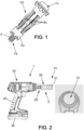
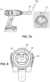
- the present disclosure relates to a portable tool 1 configured to ensure the expansion of an expansion dowel Ch of a screw Vs and dowel Ch assembly, such as a Molly dowel.
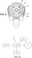
- This shoulder Ep is intended to come to bear on a first face of a wall through which the pin is inserted and as illustrated in Figure 6 . Claws can be provided on the shoulder to bite the wall.
- the ankle further comprises a plurality of branches Bv each connecting the nut Ec to the shoulder Ep.
- the expansion of the ankle is obtained by deformation of the branches, in particular folding of the branches, ensuring the rimpedement of the shoulder Ep with the nut Ec, which is itself obtained by separating the screw head Tv from the shoulder Ep, and as illustrated by way of example in Figure 6 .
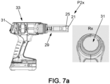
- the tool also comprises a drive mechanism configured to move the slide 24 from a first initial position P1, for which the second support 25 is juxtaposed to the first support 21.
- This first initial position authorizes the insertion of the screw through the first and second notches 22,26 then facing each other and juxtaposed, with the first support 21 coming into contact against the shoulder Ep of the expansion anchor Ch inside which the screw Vs is screwed.
- the threaded part of the screw then passes through the first notch 22 and the second notch 26 juxtaposed.
- the screw head Tv of dimension greater than the second notch 26, is then positioned opposite the second support 25, and capable of being pulled by the second support 25 when the slide 24 separates the second support 25 from the first support 21. In this position, the second support 25 is positioned intermediate between the first support 21 and the screw head Tv.
- the drive mechanism is configured to move the slide 24 from said first position P1 to a second position P2x; P2y for which the second support 25 then in contact against the screw head is moved away from the first support 21 in contact with the shoulder Ep of the ankle, by sliding of the slide 24 along the slide 23.
- This movement causes the spacing of the screw head Tv of the shoulder Ep of the dowel, and thus the expansion of the dowel Ch by deformation of the branches Br under the approximation of the nut Ec and the shoulder Ep.
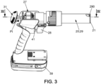
- the drive mechanism comprises an electric motor M comprising a rotor 27 and a stator, as well as a transmission ensuring the movement of the slide 24 along the slide 23 during rotation of the rotor, as well as a control module 30 comprising a control member 28.
- This control module is configured, when the operator presses said control member 28, to actuate the motor in order to drive the slide 24 from the first position P1 towards the second position P2x, P2y.
- Such a tool ensures the expansion of the ankle in a motorized manner, advantageously reducing the efforts for the user compared to a tool with a (manual) clamp mechanism.
- control member 28 is an electric button with a normally open switch, pressing on said control member 28 ensuring actuation of the electric motor M, and the release of the control member 28 l stopping the engine.
- the control member 28 and the switch can be with all or nothing operation, or alternatively advantageously with progressive operation, with control of the variation of the speed of rotation of the motor, in particular as a function of the support stroke on the control body 28.
- the tool may comprise a handle 40: said control member 28 may be a trigger configured to be pressed by a finger such as the index finger of the hand gripping the handle 40.
- control module 30 comprises a motor card CM ensuring the automatic stopping of the slide 24 in the second position P2x, P2y when the slide reaches a determined stroke between said first position P1 and said second position P2x, P2y of the slide 24, stored in the memory card.
- the motor card CM can be a card with control of the position of the motor, the card ensuring automatic stopping of the motor when the slide reaches the second position P2x, P2y and in particular even when the operator continues to press on the control member 28.
- the determined stroke is chosen here as a function of the characteristics of the expanding anchor Ch, or even of the support for placing the anchor, in particular the thickness of the wall inside which the anchor is inserted.
- the determined stroke is chosen in order to obtain the deformation of the branches ensuring optimal support of the ankle.
- control module 30 comprises a user interface 31 configured to ensure the adjustment of the value x, y of the determined stroke.
- the user interface 31 can be a rotary adjustment wheel. This adjustment wheel 31 can be integral with the rotary axis of a potentiometer Pt.
- the control module 30 then includes the motor card CM connected to the terminals of the potentiometer and associating different values x, y of the determined stroke with different values of the variable resistor at the terminals Bn of the potentiometer Pt.
- the user interface 31 can take other forms such as a digital display with one or more buttons allowing the adjustment of the stroke determined.
- a digital display with one or more buttons allowing the adjustment of the stroke determined.
- Such an interface makes it possible to adjust the value of the stroke determined according to the characteristics of the dowel and the support, and according to different dowel dimensions. It becomes possible to ensure optimal deformation of the branches during expansion of the ankle, in a repetitive and reliable manner, and advantageously whatever the ankle model.
- the adjustment of the determined stroke is preferably a fine adjustment: said user interface 31 ensures an adjustment of the value of the determined stroke preferably according to an adjustment increment less than or equal to 3 mm, preferably less than or equal to 2 mm, or even less than or equal to 1 mm, or even an adjustment of the value of the stroke determined continuously.
- the stroke of the slide can be at least equal to 44 mm.
- a stroke of the slide from the first position P1 to the second position P2x, P2y allows the installation and expansion of the dowels available on the market, even the longest.
- said user interface ensures adjustment of the value of the determined stroke over a range which extends to at least 44 mm for the determined stroke of the slide.
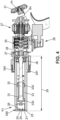
- the transmission between the rotor 27 of the electric motor M comprises a screw 32/nut 33 system, configured to transform the rotational movement of the rotor 27 of the motor M into a translational movement of the slide 24.
- the rotor 27 of the motor M causes the rotation of the screw 32 on itself preferably via a reducer 35, while the nut 33 in cooperation with the screw is movable in translation in the direction of the slide 23.
- the reduction gear 35 can be a reduction gear with an epicyclic gear train, for example multi-stage.
- the tip 20 can comprise a barrel 29 terminated at its distal end by the first support 21, and connected at its proximal end to a body 34 of the tool.
- the body 34 of the tool carries the motor M, or even said reduction gear 35 as well than the control module 30.
- the barrel can have a cylindrical external shape, the first support 21 forming the base at the distal end of the barrel.
- the barrel 29 is tubular with a housing forming a slide 23 for the slide.
- the tubular housing of the barrel is of non-circular section, for example of rectangular or even square section.
- the section of the slide is complementary to the sliding clearance, ensuring the guidance of the slide in the housing forming a slide, with blocking the rotation of the slide 24 relative to the barrel around a longitudinal axis of the barrel.
- the outer wall of the barrel 29, in particular cylindrical, has a notch 290, of dimension greater than the screw head Tv, opening opposite the first support 21, to the right of the first notch 22.
- this notch 290 allows the insertion of the screw head within the barrel, until positioning the threaded part of the screw through the first and second notches 22.26 of the first and second supports 21.25 then juxtaposed.
- the second support 25 is then positioned intermediate between the first support 21 and the screw head Tv, following the direction of the barrel.
- the screw 32 of the screw-nut system can extend internally to the barrel, guided in rotation relative to the barrel by a bearing such as a bearing 36 connecting the screw 32 and the internal wall of the barrel 29.
- the nut 33 is mounted movable in translation inside the housing, without the possibility of rotation of the nut relative to the barrel around a longitudinal axis of the barrel.
- the nut 33 may have one or more pads 330, ensuring guidance of the nut.
- the nut 33 has two pads 330 in positions offset along the axis of the barrel.
- the section of the or each shoe 330 can be complementary to the non-circular section of the housing, and in order to block the rotation of the nut 33 around its axis.
- the (or each) pad 330 has a rectangular (or even square) section complementary to the sliding clearance close to the housing section.
- the tip 20 and the body 34 of the tool comprise removable fixing means between the proximal end of the barrel 29 and the body 34 of the tool.
- the end of the screw 32 at the proximal end of the barrel, on the one hand, and the outlet of the reducer 35 of the body of the tool, on the other hand, can respectively comprise coupling parts complementary 37.38 by interlocking, removable ensuring torque transmission. These complementary parts ensure rapid coupling between the output of the reducer 35 and the screw 32 when the proximal end of the barrel is fitted into the body of the tool.
- the removable fixing means may include a retaining ring 340 ensuring the blocking of the barrel 29, fitted by its proximal end in the body 34, by pressing the retaining ring 340 against a portion 291 at the proximal end of the barrel.
- This ring 340 extends around the barrel and has an internal thread screwed onto the body 34 of the tool, ensuring the coupling of the complementary parts 37 and 38, removable. The removal of the barrel 29 first requires the removal of the retaining ring 340 by unscrewing, and before allowing the extraction of the barrel 29.
- the tool 1 is preferably powered by an autonomous electrical energy source such as a battery.
- This energy source powers the motor M and the control module 30.
- This battery 39 is possibly provided removable relative to the body 34 of the tool.
- the tool will find a particular application for the installation of expansion dowels, for example Molly
Landscapes
- Engineering & Computer Science (AREA)
- Mechanical Engineering (AREA)
- Manipulator (AREA)
- Details Of Spanners, Wrenches, And Screw Drivers And Accessories (AREA)
Claims (13)
- Tragbares Werkzeug (1), welches dazu ausgebildet ist, das Spreizen eines Dübels (Ch) einer Anordnung aus Schraube (Vs) und Dübel zu gewährleisten, wobei:- die Schraube (Vs) einen Schraubenkopf (TV) aufweist, dessen Durchmesser größer ist als ein Gewindeteil (F) der Schraube,- der Dübel (Ch), der eine Mutter (EC) auf Höhe eines distalen Endes aufweist, in deren Inneres die Schraube eingeschraubt ist, und eine Schulter (Ep) auf Höhe eines proximalen Endes aufweist, die dazu bestimmt ist, an einer ersten Seite einer Wand zur Anlage zu kommen, in deren Inneres der Dübel eingeführt ist, sowie eine Vielzahl von Schenkeln (Bv), die jeweils die Mutter (EC) mit der Schulter (Ep) verbinden, und wobei das Werkzeug einen Effektor (2) umfasst, der Folgendes umfasst:- ein Endstück (20), das an seinem distalen Ende eine erste Auflage (21) aufweist, die mit einer ersten Aussparung (22) versehen ist und eine Fläche aufweist, die dazu bestimmt ist, mit der Schulter (Ep) des Dübels in Kontakt zu kommen, sowie eine Gleitschiene (23), die sich auf der der genannten Fläche gegenüberliegenden Seite erstreckt,- einen Schieber (24), der entlang der Gleitschiene (23) translatorisch beweglich montiert ist und eine zweite Auflage (25) trägt, die mit einer zweiten Aussparung (26) versehen ist, der dazu ausgebildet ist, gegen den Schraubenkopf (TV) in Anlage zu kommen,- einen Antriebsmechanismus, der dazu ausgebildet ist, den Schieber (24) aus einer ersten Position (P1), einer Ausgangsposition, zu bewegen, in der die zweite Auflage (25) neben der ersten Auflage (21) liegt, was das Einführen der Schraube (Vs) durch die aus der ersten Aussparung (22) und der zweiten Aussparung (26) bestehenden Aussparungen erlaubt, mit einer Kontaktherstellung der ersten Auflage (21) gegen die Schulter (Ep) des Spreizdübels (Ch), in dessen Inneres die Schraube (Vs) eingeschraubt wird und dessen Gewindeabschnitt durch die ersten Aussparung (22) und die daneben liegende zweiten Aussparung (26) verläuft, wobei der Schraubenkopf (TV) dann gegenüber der zweiten Auflage (25) positioniert ist und bis zu einer zweiten Position (P2x; P2y), bei der die zweite Auflage (25), die dann in Kontakt mit dem Schraubenkopf ist, von der ersten Auflage (21), die in Kontakt mit der Schulter (Ep) ist, durch Gleiten des Schiebers (24) entlang der Gleitschiene (23) entfernt wird, was die Entfernung des Schraubenkopfs (TV) in Bezug auf die Schulter (Ep) des Dübels bewirkt, und somit das Spreizen des Dübels (Ch) durch Verformung der Schenkel (Bv) unter Annäherung der Mutter (EC) und der Schulter (Ep) bewirkt, wobei der Antriebsmechanismus einen Elektromotor (M) umfasst, mit einem Rotor (27) und einem Stator, sowie ein Getriebe, das das Bewegen des Schiebers (24) entlang der Gleitschiene (23) bei der Drehung des Rotors sicherstellt, sowie ein Steuermodul (30) umfassend ein Bedienelement (28), wobei das Steuermodul dazu ausgebildet ist, dass es, wenn der Bediener das Bedienelement (28) drückt, den Motor betätigt, um den Schieber (24) aus der ersten Position (P1) in die zweite Position (P2x, P2y) zu bewegen,wobeidas Steuerorgan (28) ein elektrischer Knopf bevorzugt mit einem normalerweise offenen Schalter ist, wobei das Drücken des Steuerorgans (28) die Betätigung des Elektromotors (M) sicherstellt und das Loslassen des Steuerorgans (28) das Anhalten des Motors bewirkt,dadurch gekennzeichnet, dass das Steuermodul (30) eine Motorkarte (CM) umfasst, die das automatische Anhalten des Schiebers (24) in der zweiten Position (P2x, P2y) sicherstellt, wenn der Schieber einen bestimmten Hub zwischen der ersten Position (P1) und der zweiten Position (P2x, P2y) des Schiebers (24) erreicht, sowie eine Benutzerschnittstelle (31), die dazu ausgebildet ist, die Einstellung des Werts (x, y) des bestimmten Hubs sicherzustellen.
- Tragbares Werkzeug nach Anspruch 1, wobei die Benutzerschnittstelle (31) ein Einstellrad ist, das drehbar ist.
- Tragbares Werkzeug nach Anspruch 2, wobei das Einstellrad (31) fest mit der Drehachse eines Potentiometers (Pt) verbunden ist, wobei das Steuermodul (30) die Motorkarte (CM) umfasst, die mit den Anschlüssen des Potentiometers verbunden ist und verschiedenen Werten des variablen Widerstands an den Anschlüssen (Bn) des Potentiometers (Pt) verschiedene Werte (x, y) des ermittelten Hubs zuordnet.
- Tragbares Werkzeug nach einem der Ansprüche 1 bis 3, wobei der Wert des Hubs in einem Bereich einstellbar ist, der sich für den Wert des ermittelten Hubs auf bis zu wenigstens 44 mm erstreckt.
- Tragbares Werkzeug nach einem der Ansprüche 1 bis 4, wobei die Benutzerschnittstelle (31) die Einstellung des ermittelten Hubwerts in einem Einstellschritt von weniger als oder gleich 3 mm, bevorzugt weniger als oder gleich 2 mm oder sogar weniger als oder gleich 1 mm, sicherstellt.
- Tragbares Werkzeug nach einem der Ansprüche 1 bis 5, wobei die Übertragung zwischen dem Rotor des Elektromotors (27) ein System aus Schraube (32)/Mutter (33) umfasst, das dazu ausgebildet ist, die Drehbewegung des Rotors (27) des Motors in eine Translationsbewegung des Schiebers (24) umzuwandeln.
- Tragbares Werkzeug nach einem der Ansprüche 1 bis 6, wobei das Endstück (20) einen Schaft (29) umfasst, der an seinem distalen Ende mit der ersten Auflage (21) endet und an seinem proximalen Ende mit einem Körper (34) des Werkzeugs verbunden ist, der den Motor aufnimmt, oder sogar ein Untersetzungsgetriebe (35) sowie das Steuermodul (30), wobei der rohrförmige Schaft eine Aufnahme umfasst, die eine Gleitschiene (23) für den Schieber (24) bildet, mit Blockierung der Drehung des Schiebers (24) in Bezug auf den Schaft um eine Längsachse des Schafts.
- Tragbares Werkzeug nach Anspruch 6 und 7, wobei sich die Schraube (32) des Schrauben-Mutter-Systems im Inneren des Schafts erstreckt, drehbar geführt durch ein Lager (36), welches die Schraube und die Innenwand des Schafts verbindet, und wobei die Mutter im Inneren des Gehäuses translatorisch beweglich montiert ist, ohne Möglichkeit der Drehung der Mutter in Bezug auf den Schaft um eine Längsachse des Schafts.
- Tragbares Werkzeug nach Anspruch 8, wobei das Endstück (20) und der Körper (34) des Werkzeugs Mittel zur lösbaren Befestigung zwischen dem proximalen Ende des Schafts (29) und dem Körper des Werkzeugs umfassen, umfassend beispielsweise einen Haltering (340), und wobei das Ende der Schraube (32) am dem proximalen Ende des Schafts einerseits und dem Ausgang des Untersetzungsgetriebes (35) des Werkzeugkörpers andererseits komplementäre Kupplungsteile (37, 38) durch Einrasten umfassen, die lösbar sind und eine Drehmomentübertragung gewährleisten.
- Tragbares Werkzeug nach einem der Ansprüche 7 bis 9, wobei sich die Benutzerschnittstelle (31) am hinteren Teil des Werkzeugkörpers befindet, diametral entgegengesetzt zu dem mit dem vorderen Teil des Werkzeugkörpers verbundenen Endstück (20).
- Tragbares Werkzeug nach einem der Ansprüche 1 bis 10, wobei das Werkzeug einen Griff (40) umfasst und wobei das Betätigungselement (28) ein Abzug ist, der dazu ausgebildet ist, von einem Finger wie dem Zeigefinger der Hand, die den Griff ergreift, gedrückt zu werden.
- Tragbares Werkzeug nach einem der Ansprüche 1 bis 11, wobei die Energiequelle des Motors (M) und des Steuermoduls (30) eine Batterie (39) ist, die eventuell in Bezug auf den Körper (34) des Werkzeugs entfernbar vorgesehen ist
- Tragbares Werkzeug nach einem der Ansprüche 1 bis 12, wobei das Steuermodul (30) einen Wähler (41) der Drehrichtung des Motors umfasst, der dazu ausgebildet ist, wenigstens zwei Zustände anzunehmen, einschließlich:- einen ersten Zustand, in dem ein Druck auf das Steuerorgan (28) die Drehung des Motors in der Richtung bewirkt, die den Vorschub des Schiebers (24) von der ersten Position (P1) in die zweite Position (P2x, P2y) ermöglicht,- einen zweiten Zustand, in dem ein Druck auf das Steuerorgan (28) die Drehung des Motors in die Richtung bewirkt, in der der Schieber aus der zweiten Position (P2x, P2y) in die erste, ursprüngliche Position (P1) zurückgezogen werden kann.
Applications Claiming Priority (1)
| Application Number | Priority Date | Filing Date | Title |
|---|---|---|---|
| FR2010727A FR3115225B1 (fr) | 2020-10-19 | 2020-10-19 | Outil portatif pour cheville à expansion |
Publications (3)
| Publication Number | Publication Date |
|---|---|
| EP3984699A1 EP3984699A1 (de) | 2022-04-20 |
| EP3984699C0 EP3984699C0 (de) | 2024-03-06 |
| EP3984699B1 true EP3984699B1 (de) | 2024-03-06 |
Family
ID=73793475
Family Applications (1)
| Application Number | Title | Priority Date | Filing Date |
|---|---|---|---|
| EP21200937.7A Active EP3984699B1 (de) | 2020-10-19 | 2021-10-05 | Tragbares werkzeug für spreizdübel |
Country Status (3)
| Country | Link |
|---|---|
| US (1) | US20220118591A1 (de) |
| EP (1) | EP3984699B1 (de) |
| FR (1) | FR3115225B1 (de) |
Family Cites Families (3)
| Publication number | Priority date | Publication date | Assignee | Title |
|---|---|---|---|---|
| GB2306368B (en) * | 1995-10-31 | 1998-08-19 | Emhart Inc | Rivet setting tool |
| GB2331950B (en) * | 1997-12-06 | 2002-08-07 | Emhart Inc | Blind rivet setting tool |
| US20200039050A1 (en) * | 2018-07-31 | 2020-02-06 | Wang-Kuan Lin | Device for Installing Expansion Bolts |
-
2020
- 2020-10-19 FR FR2010727A patent/FR3115225B1/fr active Active
-
2021
- 2021-10-05 EP EP21200937.7A patent/EP3984699B1/de active Active
- 2021-10-18 US US17/503,485 patent/US20220118591A1/en active Pending
Also Published As
| Publication number | Publication date |
|---|---|
| US20220118591A1 (en) | 2022-04-21 |
| EP3984699A1 (de) | 2022-04-20 |
| FR3115225B1 (fr) | 2022-12-30 |
| EP3984699C0 (de) | 2024-03-06 |
| FR3115225A1 (fr) | 2022-04-22 |
Similar Documents
| Publication | Publication Date | Title |
|---|---|---|
| EP1961531B1 (de) | Befestigungsvorrichtung mit versenkbarem Handhebel und Geräte eine solche Vorrichtung enthaltend | |
| EP3539685B1 (de) | Werkzeug und verfahren zum setzen einer blindbefestigung | |
| CA2779542C (en) | Insertion tool for tangless spiral coil insert | |
| FR2738764A1 (fr) | Cle a vis avec dispositif d'affichage pour afficher une limite de force de torsion sur ce dernier | |
| EP0800796A1 (de) | Schaubgerät mit Schraubenmagazin, insbesondere für die Gesichts- und Kieferchirurgie | |
| EP2669051B1 (de) | Set von vorübergehenden Befestigungselementen, und Montagevorrichtung für solche Befestigungselemente | |
| EP2999571B1 (de) | Vorrichtung zum aufbringen vorübergehender befestigungsmittel | |
| EP0727270A1 (de) | Sägeblattaufspannvorrichtung für Schneidwerkzeuge | |
| FR2888147A1 (fr) | Mecanisme d'arret et mecanisme d'ajustement de couple pour outil rotatif et outil rotatif comportant de tels mecanisme d'arret et mecanisme d'ajustement de couple | |
| EP3984699B1 (de) | Tragbares werkzeug für spreizdübel | |
| EP0706442A1 (de) | Werkzeug zum anziehen von befestigungsmitteln, insbesondere schraubendreher | |
| FR3010254A1 (fr) | Actionneur lineaire a architecture en ligne | |
| EP0618045A1 (de) | Bandschlüssel, insbesondere für Fahrzeug-Ölfilter | |
| EP2626154B1 (de) | Nase eines motorisierten Zugwerkzeugs eines gewölbten Kopfes eines Elements, und entsprechendes Werkzeug | |
| FR2793429A1 (fr) | Mandrin pour appareil d'entrainement comportant une broche rotative | |
| FR2678538A1 (fr) | Outil de vissage. | |
| WO2008025668A1 (fr) | Instrument a main a usage dentaire ou chirurgical | |
| FR2920104A1 (fr) | Mandrin porte-outil pour l'equipement d'une machine tournante | |
| FR2536689A1 (fr) | Tournevis comportant un mecanisme d'accouplement de sa tige | |
| FR2812056A1 (fr) | Actionneur electrique comportant un agencement a vis-ecrou | |
| EP1757829A2 (de) | Vorrichtung zur Erzeugung eines vordefinierten Spannungszustands bei Bedienungsvorrichtung mit einem in eine Führungshülle eingelegten Kabel | |
| FR2914578A1 (fr) | Outil debrayable permettant d'entrainer simultanement une vis et un ecrou | |
| EP1143866A1 (de) | Implantat mit markerstütze und anbringungswerkzeug | |
| FR2915122A1 (fr) | Outil de vissage comprenant une fenetre de reglage d'un couple de vissage et une trappe d'obturation de la fenetre susceptible d'etre entrainee par un mecanisme presentant des moyens d'actionnement | |
| WO2012056149A1 (fr) | Dispositif de vissage d'une vis à os |
Legal Events
| Date | Code | Title | Description |
|---|---|---|---|
| PUAI | Public reference made under article 153(3) epc to a published international application that has entered the european phase |
Free format text: ORIGINAL CODE: 0009012 |
|
| STAA | Information on the status of an ep patent application or granted ep patent |
Free format text: STATUS: THE APPLICATION HAS BEEN PUBLISHED |
|
| AK | Designated contracting states |
Kind code of ref document: A1 Designated state(s): AL AT BE BG CH CY CZ DE DK EE ES FI FR GB GR HR HU IE IS IT LI LT LU LV MC MK MT NL NO PL PT RO RS SE SI SK SM TR |
|
| STAA | Information on the status of an ep patent application or granted ep patent |
Free format text: STATUS: REQUEST FOR EXAMINATION WAS MADE |
|
| 17P | Request for examination filed |
Effective date: 20221018 |
|
| RBV | Designated contracting states (corrected) |
Designated state(s): AL AT BE BG CH CY CZ DE DK EE ES FI FR GB GR HR HU IE IS IT LI LT LU LV MC MK MT NL NO PL PT RO RS SE SI SK SM TR |
|
| RIC1 | Information provided on ipc code assigned before grant |
Ipc: B21J 15/04 20060101ALI20231101BHEP Ipc: B25B 27/00 20060101AFI20231101BHEP |
|
| GRAP | Despatch of communication of intention to grant a patent |
Free format text: ORIGINAL CODE: EPIDOSNIGR1 |
|
| STAA | Information on the status of an ep patent application or granted ep patent |
Free format text: STATUS: GRANT OF PATENT IS INTENDED |
|
| INTG | Intention to grant announced |
Effective date: 20231222 |
|
| GRAS | Grant fee paid |
Free format text: ORIGINAL CODE: EPIDOSNIGR3 |
|
| GRAA | (expected) grant |
Free format text: ORIGINAL CODE: 0009210 |
|
| STAA | Information on the status of an ep patent application or granted ep patent |
Free format text: STATUS: THE PATENT HAS BEEN GRANTED |
|
| AK | Designated contracting states |
Kind code of ref document: B1 Designated state(s): AL AT BE BG CH CY CZ DE DK EE ES FI FR GB GR HR HU IE IS IT LI LT LU LV MC MK MT NL NO PL PT RO RS SE SI SK SM TR |
|
| REG | Reference to a national code |
Ref country code: CH Ref legal event code: EP |
|
| REG | Reference to a national code |
Ref country code: IE Ref legal event code: FG4D Free format text: LANGUAGE OF EP DOCUMENT: FRENCH |
|
| REG | Reference to a national code |
Ref country code: DE Ref legal event code: R096 Ref document number: 602021010056 Country of ref document: DE |
|
| U01 | Request for unitary effect filed |
Effective date: 20240405 |
|
| U07 | Unitary effect registered |
Designated state(s): AT BE BG DE DK EE FI FR IT LT LU LV MT NL PT SE SI Effective date: 20240412 |