EP3984482B1 - Vorrichtung zur befestigung einer lichtaufnahmeeinrichtung an einem chirurgischen instrument - Google Patents
Vorrichtung zur befestigung einer lichtaufnahmeeinrichtung an einem chirurgischen instrument Download PDFInfo
- Publication number
- EP3984482B1 EP3984482B1 EP20202484.0A EP20202484A EP3984482B1 EP 3984482 B1 EP3984482 B1 EP 3984482B1 EP 20202484 A EP20202484 A EP 20202484A EP 3984482 B1 EP3984482 B1 EP 3984482B1
- Authority
- EP
- European Patent Office
- Prior art keywords
- instrument
- light
- electrode
- section
- receiving device
- Prior art date
- Legal status (The legal status is an assumption and is not a legal conclusion. Google has not performed a legal analysis and makes no representation as to the accuracy of the status listed.)
- Active
Links
Images


Classifications
-
- A—HUMAN NECESSITIES
- A61—MEDICAL OR VETERINARY SCIENCE; HYGIENE
- A61B—DIAGNOSIS; SURGERY; IDENTIFICATION
- A61B18/00—Surgical instruments, devices or methods for transferring non-mechanical forms of energy to or from the body
- A61B18/04—Surgical instruments, devices or methods for transferring non-mechanical forms of energy to or from the body by heating
- A61B18/12—Surgical instruments, devices or methods for transferring non-mechanical forms of energy to or from the body by heating by passing a current through the tissue to be heated, e.g. high-frequency current
- A61B18/14—Probes or electrodes therefor
- A61B18/1402—Probes for open surgery
-
- A—HUMAN NECESSITIES
- A61—MEDICAL OR VETERINARY SCIENCE; HYGIENE
- A61B—DIAGNOSIS; SURGERY; IDENTIFICATION
- A61B18/00—Surgical instruments, devices or methods for transferring non-mechanical forms of energy to or from the body
- A61B18/04—Surgical instruments, devices or methods for transferring non-mechanical forms of energy to or from the body by heating
- A61B18/12—Surgical instruments, devices or methods for transferring non-mechanical forms of energy to or from the body by heating by passing a current through the tissue to be heated, e.g. high-frequency current
- A61B18/14—Probes or electrodes therefor
- A61B18/1482—Probes or electrodes therefor having a long rigid shaft for accessing the inner body transcutaneously in minimal invasive surgery, e.g. laparoscopy
-
- A—HUMAN NECESSITIES
- A61—MEDICAL OR VETERINARY SCIENCE; HYGIENE
- A61B—DIAGNOSIS; SURGERY; IDENTIFICATION
- A61B18/00—Surgical instruments, devices or methods for transferring non-mechanical forms of energy to or from the body
- A61B18/04—Surgical instruments, devices or methods for transferring non-mechanical forms of energy to or from the body by heating
- A61B18/12—Surgical instruments, devices or methods for transferring non-mechanical forms of energy to or from the body by heating by passing a current through the tissue to be heated, e.g. high-frequency current
-
- A—HUMAN NECESSITIES
- A61—MEDICAL OR VETERINARY SCIENCE; HYGIENE
- A61B—DIAGNOSIS; SURGERY; IDENTIFICATION
- A61B18/00—Surgical instruments, devices or methods for transferring non-mechanical forms of energy to or from the body
-
- A—HUMAN NECESSITIES
- A61—MEDICAL OR VETERINARY SCIENCE; HYGIENE
- A61B—DIAGNOSIS; SURGERY; IDENTIFICATION
- A61B18/00—Surgical instruments, devices or methods for transferring non-mechanical forms of energy to or from the body
- A61B18/04—Surgical instruments, devices or methods for transferring non-mechanical forms of energy to or from the body by heating
- A61B18/042—Surgical instruments, devices or methods for transferring non-mechanical forms of energy to or from the body by heating using additional gas becoming plasma
-
- A—HUMAN NECESSITIES
- A61—MEDICAL OR VETERINARY SCIENCE; HYGIENE
- A61B—DIAGNOSIS; SURGERY; IDENTIFICATION
- A61B18/00—Surgical instruments, devices or methods for transferring non-mechanical forms of energy to or from the body
- A61B18/04—Surgical instruments, devices or methods for transferring non-mechanical forms of energy to or from the body by heating
- A61B18/12—Surgical instruments, devices or methods for transferring non-mechanical forms of energy to or from the body by heating by passing a current through the tissue to be heated, e.g. high-frequency current
- A61B18/1206—Generators therefor
-
- A—HUMAN NECESSITIES
- A61—MEDICAL OR VETERINARY SCIENCE; HYGIENE
- A61B—DIAGNOSIS; SURGERY; IDENTIFICATION
- A61B18/00—Surgical instruments, devices or methods for transferring non-mechanical forms of energy to or from the body
- A61B18/04—Surgical instruments, devices or methods for transferring non-mechanical forms of energy to or from the body by heating
- A61B18/12—Surgical instruments, devices or methods for transferring non-mechanical forms of energy to or from the body by heating by passing a current through the tissue to be heated, e.g. high-frequency current
- A61B18/14—Probes or electrodes therefor
- A61B18/1492—Probes or electrodes therefor having a flexible, catheter-like structure, e.g. for heart ablation
-
- A—HUMAN NECESSITIES
- A61—MEDICAL OR VETERINARY SCIENCE; HYGIENE
- A61B—DIAGNOSIS; SURGERY; IDENTIFICATION
- A61B5/00—Measuring for diagnostic purposes; Identification of persons
- A61B5/0059—Measuring for diagnostic purposes; Identification of persons using light, e.g. diagnosis by transillumination, diascopy, fluorescence
- A61B5/0075—Measuring for diagnostic purposes; Identification of persons using light, e.g. diagnosis by transillumination, diascopy, fluorescence by spectroscopy, i.e. measuring spectra, e.g. Raman spectroscopy, infrared absorption spectroscopy
-
- A—HUMAN NECESSITIES
- A61—MEDICAL OR VETERINARY SCIENCE; HYGIENE
- A61B—DIAGNOSIS; SURGERY; IDENTIFICATION
- A61B5/00—Measuring for diagnostic purposes; Identification of persons
- A61B5/0059—Measuring for diagnostic purposes; Identification of persons using light, e.g. diagnosis by transillumination, diascopy, fluorescence
- A61B5/0082—Measuring for diagnostic purposes; Identification of persons using light, e.g. diagnosis by transillumination, diascopy, fluorescence adapted for particular medical purposes
- A61B5/0084—Measuring for diagnostic purposes; Identification of persons using light, e.g. diagnosis by transillumination, diascopy, fluorescence adapted for particular medical purposes for introduction into the body, e.g. by catheters
-
- A—HUMAN NECESSITIES
- A61—MEDICAL OR VETERINARY SCIENCE; HYGIENE
- A61B—DIAGNOSIS; SURGERY; IDENTIFICATION
- A61B5/00—Measuring for diagnostic purposes; Identification of persons
- A61B5/48—Other medical applications
- A61B5/4848—Monitoring or testing the effects of treatment, e.g. of medication
-
- A—HUMAN NECESSITIES
- A61—MEDICAL OR VETERINARY SCIENCE; HYGIENE
- A61B—DIAGNOSIS; SURGERY; IDENTIFICATION
- A61B5/00—Measuring for diagnostic purposes; Identification of persons
- A61B5/68—Arrangements of detecting, measuring or recording means, e.g. sensors, in relation to patient
- A61B5/6846—Arrangements of detecting, measuring or recording means, e.g. sensors, in relation to patient specially adapted to be brought in contact with an internal body part, i.e. invasive
- A61B5/6847—Arrangements of detecting, measuring or recording means, e.g. sensors, in relation to patient specially adapted to be brought in contact with an internal body part, i.e. invasive mounted on an invasive device
-
- A—HUMAN NECESSITIES
- A61—MEDICAL OR VETERINARY SCIENCE; HYGIENE
- A61B—DIAGNOSIS; SURGERY; IDENTIFICATION
- A61B90/00—Instruments, implements or accessories specially adapted for surgery or diagnosis and not covered by any of the groups A61B1/00 - A61B50/00, e.g. for luxation treatment or for protecting wound edges
- A61B90/70—Cleaning devices specially adapted for surgical instruments
-
- A—HUMAN NECESSITIES
- A61—MEDICAL OR VETERINARY SCIENCE; HYGIENE
- A61B—DIAGNOSIS; SURGERY; IDENTIFICATION
- A61B17/00—Surgical instruments, devices or methods
- A61B17/00234—Surgical instruments, devices or methods for minimally invasive surgery
-
- A—HUMAN NECESSITIES
- A61—MEDICAL OR VETERINARY SCIENCE; HYGIENE
- A61B—DIAGNOSIS; SURGERY; IDENTIFICATION
- A61B17/00—Surgical instruments, devices or methods
- A61B2017/00017—Electrical control of surgical instruments
-
- A—HUMAN NECESSITIES
- A61—MEDICAL OR VETERINARY SCIENCE; HYGIENE
- A61B—DIAGNOSIS; SURGERY; IDENTIFICATION
- A61B17/00—Surgical instruments, devices or methods
- A61B2017/00017—Electrical control of surgical instruments
- A61B2017/00022—Sensing or detecting at the treatment site
- A61B2017/00057—Light
-
- A—HUMAN NECESSITIES
- A61—MEDICAL OR VETERINARY SCIENCE; HYGIENE
- A61B—DIAGNOSIS; SURGERY; IDENTIFICATION
- A61B17/00—Surgical instruments, devices or methods
- A61B2017/00681—Aspects not otherwise provided for
- A61B2017/00707—Dummies, phantoms; Devices simulating patient or parts of patient
-
- A—HUMAN NECESSITIES
- A61—MEDICAL OR VETERINARY SCIENCE; HYGIENE
- A61B—DIAGNOSIS; SURGERY; IDENTIFICATION
- A61B17/00—Surgical instruments, devices or methods
- A61B2017/00681—Aspects not otherwise provided for
- A61B2017/00725—Calibration or performance testing
-
- A—HUMAN NECESSITIES
- A61—MEDICAL OR VETERINARY SCIENCE; HYGIENE
- A61B—DIAGNOSIS; SURGERY; IDENTIFICATION
- A61B17/00—Surgical instruments, devices or methods
- A61B2017/00831—Material properties
- A61B2017/00902—Material properties transparent or translucent
- A61B2017/00907—Material properties transparent or translucent for light
-
- A—HUMAN NECESSITIES
- A61—MEDICAL OR VETERINARY SCIENCE; HYGIENE
- A61B—DIAGNOSIS; SURGERY; IDENTIFICATION
- A61B17/00—Surgical instruments, devices or methods
- A61B17/22—Implements for squeezing-off ulcers or the like on inner organs of the body; Implements for scraping-out cavities of body organs, e.g. bones; for invasive removal or destruction of calculus using mechanical vibrations; for removing obstructions in blood vessels, not otherwise provided for
- A61B2017/22072—Implements for squeezing-off ulcers or the like on inner organs of the body; Implements for scraping-out cavities of body organs, e.g. bones; for invasive removal or destruction of calculus using mechanical vibrations; for removing obstructions in blood vessels, not otherwise provided for with an instrument channel, e.g. for replacing one instrument by the other
- A61B2017/22074—Implements for squeezing-off ulcers or the like on inner organs of the body; Implements for scraping-out cavities of body organs, e.g. bones; for invasive removal or destruction of calculus using mechanical vibrations; for removing obstructions in blood vessels, not otherwise provided for with an instrument channel, e.g. for replacing one instrument by the other the instrument being only slidable in a channel, e.g. advancing optical fibre through a channel
-
- A—HUMAN NECESSITIES
- A61—MEDICAL OR VETERINARY SCIENCE; HYGIENE
- A61B—DIAGNOSIS; SURGERY; IDENTIFICATION
- A61B17/00—Surgical instruments, devices or methods
- A61B17/22—Implements for squeezing-off ulcers or the like on inner organs of the body; Implements for scraping-out cavities of body organs, e.g. bones; for invasive removal or destruction of calculus using mechanical vibrations; for removing obstructions in blood vessels, not otherwise provided for
- A61B2017/22079—Implements for squeezing-off ulcers or the like on inner organs of the body; Implements for scraping-out cavities of body organs, e.g. bones; for invasive removal or destruction of calculus using mechanical vibrations; for removing obstructions in blood vessels, not otherwise provided for with suction of debris
-
- A—HUMAN NECESSITIES
- A61—MEDICAL OR VETERINARY SCIENCE; HYGIENE
- A61B—DIAGNOSIS; SURGERY; IDENTIFICATION
- A61B17/00—Surgical instruments, devices or methods
- A61B17/28—Surgical forceps
- A61B17/29—Forceps for use in minimally invasive surgery
- A61B17/2909—Handles
- A61B2017/2912—Handles transmission of forces to actuating rod or piston
- A61B2017/2913—Handles transmission of forces to actuating rod or piston cams or guiding means
- A61B2017/2917—Handles transmission of forces to actuating rod or piston cams or guiding means with flexible part
-
- A—HUMAN NECESSITIES
- A61—MEDICAL OR VETERINARY SCIENCE; HYGIENE
- A61B—DIAGNOSIS; SURGERY; IDENTIFICATION
- A61B17/00—Surgical instruments, devices or methods
- A61B17/32—Surgical cutting instruments
- A61B17/320068—Surgical cutting instruments using mechanical vibrations, e.g. ultrasonic
- A61B2017/32007—Surgical cutting instruments using mechanical vibrations, e.g. ultrasonic with suction or vacuum means
-
- A—HUMAN NECESSITIES
- A61—MEDICAL OR VETERINARY SCIENCE; HYGIENE
- A61B—DIAGNOSIS; SURGERY; IDENTIFICATION
- A61B18/00—Surgical instruments, devices or methods for transferring non-mechanical forms of energy to or from the body
- A61B2018/00053—Mechanical features of the instrument of device
- A61B2018/00059—Material properties
- A61B2018/00071—Electrical conductivity
- A61B2018/00077—Electrical conductivity high, i.e. electrically conducting
-
- A—HUMAN NECESSITIES
- A61—MEDICAL OR VETERINARY SCIENCE; HYGIENE
- A61B—DIAGNOSIS; SURGERY; IDENTIFICATION
- A61B18/00—Surgical instruments, devices or methods for transferring non-mechanical forms of energy to or from the body
- A61B2018/00053—Mechanical features of the instrument of device
- A61B2018/00172—Connectors and adapters therefor
-
- A—HUMAN NECESSITIES
- A61—MEDICAL OR VETERINARY SCIENCE; HYGIENE
- A61B—DIAGNOSIS; SURGERY; IDENTIFICATION
- A61B18/00—Surgical instruments, devices or methods for transferring non-mechanical forms of energy to or from the body
- A61B2018/00571—Surgical instruments, devices or methods for transferring non-mechanical forms of energy to or from the body for achieving a particular surgical effect
- A61B2018/00577—Ablation
-
- A—HUMAN NECESSITIES
- A61—MEDICAL OR VETERINARY SCIENCE; HYGIENE
- A61B—DIAGNOSIS; SURGERY; IDENTIFICATION
- A61B18/00—Surgical instruments, devices or methods for transferring non-mechanical forms of energy to or from the body
- A61B2018/00571—Surgical instruments, devices or methods for transferring non-mechanical forms of energy to or from the body for achieving a particular surgical effect
- A61B2018/00589—Coagulation
-
- A—HUMAN NECESSITIES
- A61—MEDICAL OR VETERINARY SCIENCE; HYGIENE
- A61B—DIAGNOSIS; SURGERY; IDENTIFICATION
- A61B18/00—Surgical instruments, devices or methods for transferring non-mechanical forms of energy to or from the body
- A61B2018/00571—Surgical instruments, devices or methods for transferring non-mechanical forms of energy to or from the body for achieving a particular surgical effect
- A61B2018/00601—Cutting
-
- A—HUMAN NECESSITIES
- A61—MEDICAL OR VETERINARY SCIENCE; HYGIENE
- A61B—DIAGNOSIS; SURGERY; IDENTIFICATION
- A61B18/00—Surgical instruments, devices or methods for transferring non-mechanical forms of energy to or from the body
- A61B2018/00571—Surgical instruments, devices or methods for transferring non-mechanical forms of energy to or from the body for achieving a particular surgical effect
- A61B2018/00607—Coagulation and cutting with the same instrument
-
- A—HUMAN NECESSITIES
- A61—MEDICAL OR VETERINARY SCIENCE; HYGIENE
- A61B—DIAGNOSIS; SURGERY; IDENTIFICATION
- A61B18/00—Surgical instruments, devices or methods for transferring non-mechanical forms of energy to or from the body
- A61B2018/00636—Sensing and controlling the application of energy
- A61B2018/00696—Controlled or regulated parameters
- A61B2018/00702—Power or energy
-
- A—HUMAN NECESSITIES
- A61—MEDICAL OR VETERINARY SCIENCE; HYGIENE
- A61B—DIAGNOSIS; SURGERY; IDENTIFICATION
- A61B18/00—Surgical instruments, devices or methods for transferring non-mechanical forms of energy to or from the body
- A61B2018/00636—Sensing and controlling the application of energy
- A61B2018/00904—Automatic detection of target tissue
-
- A—HUMAN NECESSITIES
- A61—MEDICAL OR VETERINARY SCIENCE; HYGIENE
- A61B—DIAGNOSIS; SURGERY; IDENTIFICATION
- A61B18/00—Surgical instruments, devices or methods for transferring non-mechanical forms of energy to or from the body
- A61B2018/00982—Surgical instruments, devices or methods for transferring non-mechanical forms of energy to or from the body combined with or comprising means for visual or photographic inspections inside the body, e.g. endoscopes
-
- A—HUMAN NECESSITIES
- A61—MEDICAL OR VETERINARY SCIENCE; HYGIENE
- A61B—DIAGNOSIS; SURGERY; IDENTIFICATION
- A61B18/00—Surgical instruments, devices or methods for transferring non-mechanical forms of energy to or from the body
- A61B18/04—Surgical instruments, devices or methods for transferring non-mechanical forms of energy to or from the body by heating
- A61B18/12—Surgical instruments, devices or methods for transferring non-mechanical forms of energy to or from the body by heating by passing a current through the tissue to be heated, e.g. high-frequency current
- A61B18/1206—Generators therefor
- A61B2018/1213—Generators therefor creating an arc
-
- A—HUMAN NECESSITIES
- A61—MEDICAL OR VETERINARY SCIENCE; HYGIENE
- A61B—DIAGNOSIS; SURGERY; IDENTIFICATION
- A61B18/00—Surgical instruments, devices or methods for transferring non-mechanical forms of energy to or from the body
- A61B18/04—Surgical instruments, devices or methods for transferring non-mechanical forms of energy to or from the body by heating
- A61B18/12—Surgical instruments, devices or methods for transferring non-mechanical forms of energy to or from the body by heating by passing a current through the tissue to be heated, e.g. high-frequency current
- A61B18/1206—Generators therefor
- A61B2018/1246—Generators therefor characterised by the output polarity
- A61B2018/1253—Generators therefor characterised by the output polarity monopolar
-
- A—HUMAN NECESSITIES
- A61—MEDICAL OR VETERINARY SCIENCE; HYGIENE
- A61B—DIAGNOSIS; SURGERY; IDENTIFICATION
- A61B18/00—Surgical instruments, devices or methods for transferring non-mechanical forms of energy to or from the body
- A61B18/04—Surgical instruments, devices or methods for transferring non-mechanical forms of energy to or from the body by heating
- A61B18/12—Surgical instruments, devices or methods for transferring non-mechanical forms of energy to or from the body by heating by passing a current through the tissue to be heated, e.g. high-frequency current
- A61B18/1206—Generators therefor
- A61B2018/1246—Generators therefor characterised by the output polarity
- A61B2018/126—Generators therefor characterised by the output polarity bipolar
-
- A—HUMAN NECESSITIES
- A61—MEDICAL OR VETERINARY SCIENCE; HYGIENE
- A61B—DIAGNOSIS; SURGERY; IDENTIFICATION
- A61B90/00—Instruments, implements or accessories specially adapted for surgery or diagnosis and not covered by any of the groups A61B1/00 - A61B50/00, e.g. for luxation treatment or for protecting wound edges
- A61B90/36—Image-producing devices or illumination devices not otherwise provided for
- A61B90/361—Image-producing devices, e.g. surgical cameras
- A61B2090/3614—Image-producing devices, e.g. surgical cameras using optical fibre
-
- A—HUMAN NECESSITIES
- A61—MEDICAL OR VETERINARY SCIENCE; HYGIENE
- A61B—DIAGNOSIS; SURGERY; IDENTIFICATION
- A61B2218/00—Details of surgical instruments, devices or methods for transferring non-mechanical forms of energy to or from the body
- A61B2218/001—Details of surgical instruments, devices or methods for transferring non-mechanical forms of energy to or from the body having means for irrigation and/or aspiration of substances to and/or from the surgical site
- A61B2218/002—Irrigation
-
- A—HUMAN NECESSITIES
- A61—MEDICAL OR VETERINARY SCIENCE; HYGIENE
- A61B—DIAGNOSIS; SURGERY; IDENTIFICATION
- A61B2505/00—Evaluating, monitoring or diagnosing in the context of a particular type of medical care
- A61B2505/05—Surgical care
-
- A—HUMAN NECESSITIES
- A61—MEDICAL OR VETERINARY SCIENCE; HYGIENE
- A61B—DIAGNOSIS; SURGERY; IDENTIFICATION
- A61B5/00—Measuring for diagnostic purposes; Identification of persons
- A61B5/0048—Detecting, measuring or recording by applying mechanical forces or stimuli
- A61B5/0055—Detecting, measuring or recording by applying mechanical forces or stimuli by applying suction
-
- A—HUMAN NECESSITIES
- A61—MEDICAL OR VETERINARY SCIENCE; HYGIENE
- A61B—DIAGNOSIS; SURGERY; IDENTIFICATION
- A61B5/00—Measuring for diagnostic purposes; Identification of persons
- A61B5/68—Arrangements of detecting, measuring or recording means, e.g. sensors, in relation to patient
- A61B5/6801—Arrangements of detecting, measuring or recording means, e.g. sensors, in relation to patient specially adapted to be attached to or worn on the body surface
- A61B5/683—Means for maintaining contact with the body
- A61B5/6834—Means for maintaining contact with the body using vacuum
-
- A—HUMAN NECESSITIES
- A61—MEDICAL OR VETERINARY SCIENCE; HYGIENE
- A61B—DIAGNOSIS; SURGERY; IDENTIFICATION
- A61B90/00—Instruments, implements or accessories specially adapted for surgery or diagnosis and not covered by any of the groups A61B1/00 - A61B50/00, e.g. for luxation treatment or for protecting wound edges
- A61B90/36—Image-producing devices or illumination devices not otherwise provided for
Definitions
- the present disclosure relates to the field of analyzing light phenomena, e.g., sparks, that can be produced by HF surgical instruments.
- An additional device for an endoscope for detecting fluorescent light and/or remitted light.
- the endoscope tube contains an imaging channel and an illumination channel in addition to the working channel.
- An additional optical device directs emitted fluorescent light and/or remitted light to a spectrometer.
- a monitor for displaying the spectra can be connected to the spectrometer.
- EP 3 284 430 A1 and EP 2 659 846 A1 discloses an instrument having an electrode and light receiving devices which can be oriented in different orientations towards the electrode.
- US 2009/0088772 A1 shows a robot-carryable instrument having a distal working section and an optical fiber capable of transmitting light for analyzing the light from the distal end of the instrument.
- EP 2 815 713 A1 A light guide is arranged in an electrode.
- optical fibers are used as a light capture device. These devices are connected to an analysis device for determining light characteristics and can provide the user with information about the biological tissue during the procedure. Blood, tissue fluid, smoke gas (aerosol), contact of the distal end of the optical fiber with tissue, contact of the optical fiber with tissue, flaking of tissue and splashing of tissue particles can contaminate the optical fiber and thus noticeably reduce or even completely prevent the transmission of light to the delivery unit. Tissue adhesion to the distal end of the analysis device, which can indirectly lead to shading of the optical fiber, can also reduce the light transmission.
- Contamination of the optical fiber can distort the intensity of the light signal, as the light can be absorbed to varying degrees by the contaminants. Condensation of liquid on the fiber can also briefly alter the transmission. Contamination can also alter the transmission depending on the wavelength, which can lead to a falsification of the analysis result.
- High energy input e.g., 300 watts
- high temperatures e.g., greater than 300°C
- High temperatures can also damage the optical fiber. thermal damage, which can also reduce or completely prevent the transmission of light.
- the object of the present invention is to provide an improved concept for a light receiving device.
- the light receiving device can, for example, only be attached to a handle of the Instruments can be attached if the acquisition of tissue information by light analysis is clinically desired.
- the light recording device can be easily replaced by the user with a new, clean light recording device.
- the device preferably does not have to be destroyed for this purpose.
- the connection of the light recording device to the surgical instrument by means of the device is preferably possible without tools.
- the device can preferably be plugged onto the instrument or, at least partially, pushed into the instrument and/or the instrument can preferably be plugged into the device or, at least partially, pushed into the device and/or the device can be plugged into the instrument or, at least partially, pushed.
- the device is configured for attaching, during an operation (in the operating room), for example after a surgical step has been performed with the instrument, a light-receiving device (in particular an optical fiber) for light analysis to a functional surgical instrument by a medically trained user, for example a physician.
- a light-receiving device in particular an optical fiber
- the instrument is already functional without the device and the light-receiving device if the light-receiving device is attached to the instrument by means of the device.
- the instrument component can already be connected to an electrode before being connected to the device, so that the instrument component forms a functional HF-surgical instrument with the electrode.
- the device comprises an electrode and a light receiving device
- the device is configured to predetermine the spatial relative position (relative position and/or relative orientation) of the electrode and the light-receiving device relative to one another.
- a relative position and/or relative orientation can be enabled, or a relative position and/or relative orientation can be selectable from a plurality of possible relative positions and/or relative orientations.
- at least one or exactly a single degree of freedom of the relative position and/or relative orientation can be changeable.
- a single or a plurality of relative positions and/or relative orientations between the light-receiving device and the electrode can be predetermined.
- the electrode can be arranged on the device in a plurality of different rotational positions about its longitudinal axis.
- the one or more specified orientations can differ from excluded orientations in that the light-receiving device is, for example, oriented obliquely toward a spatula surface in each of the orientations or toward a spatula surface in the only orientation.
- the device can be connectable to a handle and can be configured to thus supplement the handle to form a functional instrument by means of the electrode, which is integrated into the device or represents a standalone component.
- the handle can preferably also be supplemented with an electrode to form a functional instrument without attaching the light-receiving device to the instrument by means of the device.
- the instrument component itself for example the handle, is therefore preferably designed to carry an electrode.
- the device preferably defines a predetermined discrete, e.g., discrete values and/or mutually separate ranges, and/or, at least in certain regions, a continuous selection of possible spatial relative positions of the attached light-receiving device relative to the instrument. All relative positions of the selection are characterized in that it is ensured (if the device, instrument, and light-receiving device are intended for one another) that a sufficient amount of light from the light phenomenon (e.g., a spark or a continuously maintained plasma) caused by the instrument can be recorded by the light-receiving device.
- a sufficient amount of light from the light phenomenon e.g., a spark or a continuously maintained plasma
- the selection can include a single possible relative position or several possible relative positions.
- the spatial relative position is determined by the position and orientation of the light-receiving device, in particular the light input of the light-receiving device, relative to the instrument or the instrument component of the instrument, for example, the electrode or the handle.
- the selection may include a discrete selection of possible relative positions and/or a non-discrete (continuous) selection of possible relative positions.
- the device only has a discrete Selection of a finite number of predefined relative positions is permitted.
- the device does not specify a discrete subselection, but rather a non-discrete selection or adjustment of relative positions is possible.
- a non-discrete selection of possible relative positions means, in particular, that the user can change the relative position from a current relative position—and beyond the play within the current relative position. In the process, further possible relative positions can be continuously cycled through.
- the spatial relative position of the fixed light-receiving device is preferably completely fixed relative to the instrument by means of the device (relative position of a discrete selection or subselection of one or more relative positions) or, for example, up to one or two degrees of freedom (relative position in a continuous subselection of possible relative positions).
- the device can, for example, fix the spatial relative position up to one or two angles.
- the degree of freedom or one of the degrees of freedom that is not fixed or only fixed up to a selection of a value range can, for example, be the angle of the light recording around the instrument, for example around an electrode of the instrument.
- the device can, for example, completely fix the spatial relative position (only a single relative position is possible), whereby this can include a slight play of the instrument in or with respect to the device, for example in a longitudinal direction of the instrument or device, a radial direction and/or a rotational direction, which does not impair the light analysis.
- mobility of the light-receiving device relative to the instrument for example relative to an electrode of the instrument, by means of the device in such a way that, in all remaining positions of the light-receiving device relative to the instrument, for example relative to the electrode, reliable light reception by the light-receiving device from the region in which the sparks and/or plasma arise due to the action of the instrument is ensured.
- the light acceptance cone encompasses or encloses the region in which the light phenomena are generated in all positions that the device allows for the light-receiving device and the instrument relative to one another.
- a light receiving device can be used on an instrument for open surgery, for example an HF handle with an HF electrode (also called (HF) applicator), an instrument for laparoscopy or an instrument for flexible endoscopy, such as flexible probes for argon plasma coagulation.
- an HF handle with an HF electrode also called (HF) applicator
- an instrument for laparoscopy or an instrument for flexible endoscopy, such as flexible probes for argon plasma coagulation.
- the device defines a predetermined selection of spatial relative positions of the attached light-receiving device relative to the instrument, misalignment of the light-receiving device by the user of the instrument is excluded.
- the user as a physician, is trained in the medical use of the instrument, but not in locating a position of the light-receiving device relative to the instrument so that the light-receiving device can function.
- an intervention by the physician using an HF surgical instrument may initially involve opening and exposing the surgical site using an HF surgical instrument. Cutting instrument and then preparation for tissue differentiation. When opening and exposing the surgical site, adjustments to the electrical parameters for cutting may be necessary, which enable efficient hemostasis, but can also result in significant thermal damage.
- the instrument has an electrode that can be subjected to RF energy, so that the instrument can be used independently of the device for an RF surgical procedure.
- the electrode of the instrument for example of the RF applicator, can be replaceable.
- the instrument can, for example, be an RF applicator with a handle that has an electrode.
- the electrode can be replaceably attachable to the handle.
- the handle can allow the position and orientation of the electrode to be changed except for a single or a discrete selection of possibilities in relation to the handle.
- the Device may, for example, comprise both the light receiving device and an electrode.
- the orientation and distance of the light-receiving device, in particular of the light input of the light-receiving device, relative to the electrode are predetermined, a certain informative value and quality of the light analysis by means of the light-receiving device can be ensured.
- the device preferably has a receptacle which limits the mobility of the instrument in the receptacle to mobility in one direction, in particular an axial direction of the instrument, the electrode, the receptacle and/or the device.
- the device determines by means of the receptacle that the instrument, when fastened in the direction, in particular the axial direction, is to be inserted into the receptacle.
- the receptacle may be configured to limit the movement of the instrument or instrument component in the axial direction toward the distal end of the device.
- the device preferably comprises a device for subsequently fixing the axial position of the instrument in the receptacle, up to a maximum of an axial play that does not impair the light analysis, e.g., because the tip of the electrode always remains within a light acceptance cone of the light receiving device despite the play.
- the device for subsequent fixing can be configured to limit the movement of the instrument or instrument component in the axial direction in the direction away from the distal end of the device.
- the device for subsequently fixing the axial position preferably has a section which is laterally movable relative to the axial direction of the instrument and/or the device and/or the electrode during the fastening of the light-receiving device to the instrument.
- This movable section is preferably designed to be brought into engagement with the instrument after the instrument has been arranged in the receptacle by lateral movement of the section in order to fix the axial position of the instrument in the receptacle.
- the movable section is preferably flexibly fastened to the remaining device in order to be able to move the section laterally. This is preferred over embodiments in which the movable section is articulated or hinged to another section of the instrument.
- the section is preferably elastic, so that after the section has been moved, it Once the instrument is placed in the device, it automatically returns to its original position due to the spring force.
- the flexible section eliminates the need for a hinge, which simplifies device manufacturing and makes it easier to sterilize and/or clean.
- the device preferably has a flushing channel, wherein the flushing channel is configured to discharge a flushing medium, for example, carbon dioxide, noble gas, nitrogen, or another chemically inert gas or gas mixture, preferably in a laminar flow, along the light receiving device past the light input of the light receiving device.
- a flushing medium for example, carbon dioxide, noble gas, nitrogen, or another chemically inert gas or gas mixture, preferably in a laminar flow
- the device is configured to define the spatial position of the rinsing channel relative to the light receiver to a, in particular discrete, selection of spatial relative positions or to a single spatial relative position.
- the rinsing flow is preferably directed in the direction in which the light receiver or its light input faces, i.e., in the direction of the central axis of the light acceptance cone.
- the rinsing flow can be deflected at the light input or between the light input and the area of influence of the RF electrode, obliquely up to 90° to the optical axis, for example by a baffle plate or by a one-sided elevation in the flow channel, in order to serve as a particle barrier.
- the flow of irrigation medium is too strong, tissue can be displaced. To ensure high precision, this must be avoided, especially during preparation, i.e. the precise exposure or exposure of anatomical structures.
- the volume flow of irrigation medium must be sufficient to reliably prevent contamination of the light input and/or to ensure adequate cooling of the electrode.
- gaseous or liquid media such as smoke, blood or liquid fat can be displaced.
- the light input of the light receiver is arranged within the device to protect the light input from contamination.
- the device can thus shield the light input from liquid droplets or particles entering from certain angles without impairing the light entering the light input from other angles.
- the light input can, for example, be arranged within the flushing channel, or the light receiver can end in the flushing channel.
- a particularly compact design can be obtained if the light receiving device - for example a straight end section of the light receiving device, which can be adjacent to the light input - and/or the optical axis of the light receiving device and/or the central axis of the light acceptance cone of the light receiving device and the electrode enclose an acute angle, for example less than 15°.
- a channel section of the rinsing channel is preferably formed, which is delimited on the one hand by a wall of the device and on the other hand by a first longitudinal side of an electrode and/or an electrode shaft of the device.
- the channel section can be flowed through by rinsing medium.
- a second longitudinal side of the electrode and/or the electrode shaft, opposite the first longitudinal side, is preferably exposed at least in sections along the channel. As the rinsing medium flows through the channel section, it can cool the electrode on the first longitudinal side.
- the second longitudinal side is exposed, thus in particular having contact with the environment of the device, in particular air contact or contact with the gaseous or aerosol-like ambient medium, and can thus dissipate sufficient heat so that the electrode as a whole does not heat up excessively during operation.
- the volume flow of rinsing medium can thus be set to a rate that ensures sufficient cooling of the electrode - and preferably also a sufficient shielding and/or cleaning of the light input from contamination - guaranteed.
- the light receiving device for example an optical fiber, preferably extends continuously from the light input in and/or adjacent to the device—without an optical interface in between—proximally beyond the device to transmit light for analysis. This is advantageous because an optical interface can become contaminated if no light receiving device with a light input is connected to it for part of the surgical procedure.
- the instrument can, for example, be an HF surgical cutting, coagulation, and/or devitalization instrument.
- the instrument can, for example, be configured to operate with an ionizable gas that is converted into a plasma state.
- the instrument can, in particular, be an argon plasma coagulation (APC) instrument.
- APC argon plasma coagulation
- the instrument can be configured to utilize a dielectric barrier discharge.
- an arrangement comprising an instrument and a device according to the invention is also specified such that in the arrangement a light receiving device is attached to the instrument by means of the device.
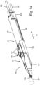
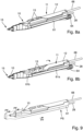
- the device 10 has a distal portion 17 into which the applicator 11 is inserted.
- the proximal end portion 18 of the distal portion 17 of the device 10 has a half-shell shape that accommodates the applicator 11.
- the half-shell shape 18 is open on a longitudinal side 19 (top side) to provide access to the operating elements 13 of the instrument 11 on the top side 20 of the instrument 11.
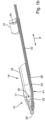
- the device 10 has, as exemplified in particular in the Figure 2b shown, also has a partially channel-like second receptacle 27 for a line 28, for example a hose or a tube, through which the at least one optical fiber, i.e. a single optical fiber or a bundle of optical fiber strands, extends as a light receiving device 24 in the direction of the distal end 29 of the distal section 17 of the device 10.
- the line 28 is fixed in the second receptacle 27, preferably by force and/or frictional engagement with the wall surface 30 of the second receptacle 27, against movement of the line 28 in the second receptacle 27.
- the end section 34 of the optical fiber 24, which protrudes from the distal end 32 of the line 28, can for this purpose be mounted on a longitudinal section through the device ( Figure 2b ) base-like or projection-like support section 39 of the receiving wall 40 of the distal section 17 of the device 10 and be firmly connected thereto, for example, by a material fit, in order to stabilize the end section 34 of the optical fiber 24 in this position.
- the optical fiber 24 is pressed against the support section 39 by its internal stress due to the bend 41 of the optical fiber 24 in the line 28. This determines the position of the optical fiber 24 relative to the longitudinal axis L of the first receptacle 25. This also applies to the direction perpendicular to the plane of the drawing in Figure 2b .
- the receiving area 42 of the support section 39 can, for example, be half-shell-shaped in order to determine the position of the optical fiber 24 together with the residual stress of the optical fiber 24 transversely to the plane spanned by the end section 34 of the optical fiber 24 and the longitudinal axis L (axial direction) of the first receptacle 25 or the axial direction of the electrode 15.
- the optical fiber 24 preferably does not terminate flush with the device 10 and does not protrude from the device 10. Rather, the optical fiber 24 terminates, as shown Figures 2b , 4d , preferably set back relative to the distal end 29 of the device 10 within a channel-shaped region 44 to avoid direct contamination of the optical fiber 24 from certain angles.
- the region 44 of the device 10 is preferably open to one side.
- the region 44 can, for example, if the proximal end section 18 of the distal section 17 is also open (e.g., upwards into, for example, the Figures 1b and 2a ), be open to the same side. This is particularly evident from the Figures 1b , 2a and 2b , in which the device 10 is shown without a connection being established between the device 10 and the instrument 11. To the opposite side ("Downward"), however, the region 44 is preferably closed.
- the half-shell formed by the proximal end section 18 of the distal section 17 can, in exemplary embodiments, be free of perforations and, in particular, be closed laterally.
- the device 10 has two side wall sections 45a, 45b in the region 44, which extend laterally past the optical fiber 24, so that the distal end 38 of the optical fiber 24 is set back relative to the distal end 29 of the device 10. This protects the light inlet 31 at the end face of the optical fiber 24 at least from particles and/or droplets that move from certain angles towards the light inlet 31.
- the side wall sections 45a, 45b are connected via a bottom wall section 46, so that the region 44 or the device 10 can have a U- or V-shaped cross-section there, for example, as can be seen from Figure 2b in conjunction with Figure 3a
- the support section 39 is at least partially formed by the base section 46.
- the free end 38 of the optical fiber 24 can project slightly beyond the support section 39 and thus be slightly spaced in all radial directions from the wall sections 45a, 45b, 46 of the device 10 in the region 44. This prevents excessive shading of the light acceptance cone 47 of the optical fiber 24 by the device 10.
- the light acceptance cone 47 is in the Figures 1a , 4c and 4d are shown with dashed lines for illustration purposes.
- the light acceptance cone 47 includes all directions from which the optical fiber 24 receives light into its light input 31 and transmits it to an analysis device can transmit, with which the light can be analyzed.
- a working section 15a of the electrode 15 is fixed in the electrode receiving shaft 14.
- the light acceptance cone 47 contains the tip or distal end 50a of the electrode 15 or of the working section 15a.
- the position and/or orientation of the electrode 15, in particular its working section 15a or tip 50, relative to the form-fitting section 26 of the instrument 11 is clearly defined.
- the position and/or orientation of the optical fiber 24 relative to the first receptacle 25 is clearly defined.
- the form-fitting section 26, together with the first receptacle 25, ensures a defined position of the optical fiber 24 relative to the electrode 15, in particular to its working section 15a, when connected between the device 10 and the instrument 11.
- the form-fitting connection between the device 10 and the instrument 11 ensures that the position and/or orientation of the optical fiber 24, when connected between the device 10 and the instrument 11, allows a light analysis of the light phenomena generated by the working section 15a of the electrode 15.
- the position of the electrode 15 relative to the instrument 11 and/or the device can be fixed, but the orientation of the electrode 15 about its longitudinal axis ELA can be freely selectable within a continuous selection.
- a section of the electrode 15 may belong to the form-fitting section 26 of the applicator 11.
- a section of the electrode receiving shaft 14 of the electrode 15 of the applicator 11 belongs to the form-fitting section 26.
- the form-fitting section 26 has a shape which leads to a corresponding complementary counter-shape of the first receptacle 25 of the device 10.
- the electrode receiving shaft 14 has a cylindrical shape which fits into the cylindrical shape (bore) of the first receptacle 25.
- these can, for example, have matching polyhedral shapes, e.g. a rectangular shape.
- the relative mobility of the form-fitting section 26 in the first receptacle 25 and with respect to the first receptacle 25 in all directions perpendicular to the central axis MA of the first receptacle 25 or to the longitudinal axis LA of the electrode receiving shaft 14 and thus also relative to the working section 15a of the electrode 15 is prevented.
- the first receiving channel 25 which can be closed in all radial directions, the position of the electrode 15 relative to the end section 34 of the optical fiber 24 is fixed radially in all directions.
- a corresponding first attack 51 is formed by a wall section 52 of the device 10. This lies against a first counter-stop 53 (see in particular Figure 4d ) of the applicator 11 axially opposite each other when the applicator 11 is advanced into the first receptacle 25.
- the first counter-stop 53 can be formed, for example, by the electrode receiving shaft 14 or, as shown, by an electrode shaft overmolding, which is a section of the handle part 12.
- the first stop 51 and the first counter-stop 52 serve to determine the position of the optical fiber 24 in the direction of the electrode tip 50a or in the axial direction of the electrode 15 or the electrode receiving shaft 14.
- the maximum distance between the electrode tip 50a and the light input 31 is determined by means of the first stop 51 and the first counter-stop 52.
- the position of the optical fiber 24 relative to the electrode 15 is preferably set such that the optical fiber 24 points toward an area in front of the tip 50a of the electrode 15.
- the optical axis OA of the optical fiber 24 intersects an area in front of the electrode tip 50a—preferably the longitudinal axis ELA of the electrode 15—at a point in front of the tip 50a of the electrode 15.
- a second stop 54 for axially securing and, in particular, positioning the applicator 11 is formed on the proximal portion 18 of the device 10.
- a second counter-stop 55 of the instrument 11 is formed in the exemplary embodiment by the proximal end of the applicator 11 (see Figure 4c ). The second stop 54 and the second counter-stop 55 prevent unwanted movement of the applicator 11 away from the distal end 29 of the device 10. This allows a minimum distance to be maintained between the electrode tip 50a and the light input 31 of the optical fiber 24.
- the electrode tip 50a remains in the light acceptance cone 47 of the optical fiber 24 when the connection is established between the device 10 and the instrument 11, as Figures 4c and 4d
- the light acceptance cone 47 of the optical fiber 24 is preferably aligned so that the tip 50a of the RF electrode 15 is located in the center of the light acceptance cone 47 in such a way as to detect the light phenomena to the left and right (on one as well as on the opposite narrow side) around the electrode 15.
- the diameter of the light input 31 of the optical fiber 24 should be as large as possible, and the light input 31 should be positioned as close as possible to the location of the light phenomenon, for example, an RF spark, at the electrode tip 50a.
- the light input 31 of the optical fiber 24 would have to be as far as possible from the location of the light phenomenon.
- the working section 15a of the electrode 15 can, for example, be spatula-shaped (as shown) or needle-shaped.
- the electrode 15 protrudes from the distal end 29 of the device 10 or protrudes beyond the distal end 29 of the device 10 in the distal direction.
- the electrode 15 is, for example, oriented such that a flat side (this can also be referred to as a flat side or spatula side) 50b of the electrode 15 faces obliquely towards the light input 31 of the optical fiber 24.
- the electrode 15 can be oriented such that Light input 31 faces a narrow side (can also be referred to as narrow side or edge) 50d, 50e of the electrode 15.
- the rotational orientation of the device 10 or the optical fiber 24 about the longitudinal axis ELA of the electrode 15, for example the longitudinal axis of the spatula-shaped working section 15a, can be determined, for example, when connecting the instrument 11 to the device 10, for example by means of an alignment structure 56 and a counter-alignment structure 57.
- An exemplary alignment structure 56 and counter-alignment structure 57 are shown in Figure 4e shown.
- a pair of an alignment structure 56 and a counter-alignment structure 57 can, for example, consist of a recess 56 and a projection 57, wherein the projection 57 is to be pushed into the recess 56 relative to the recess 56.
- the recess 56 and/or the projection 57 can, as shown, be designed such that their width B decreases at the entrance of the recess 56 in the sliding direction.
- An alignment structure 56 on the circumference of the applicator 11 engages with a counter-alignment structure 57 of the device 10, for example when the electrode 15 is pushed forward into the first receptacle 25, so that the alignment of the optical fiber 24 about the longitudinal axis ELA of the electrode 15 is determined when the instrument 11 is connected to the device 10.
- the alignment structure 56 can alternatively be formed on the device 10 and the counter-alignment structure 57 on the instrument 11.
- the arrow P illustrates the sliding direction in which the instrument 11 is advanced into the device 10 when establishing the connection.
- the user of the device can proceed as follows: The user presses the proximal section 21 of the device 10 laterally away from a longitudinal axis of the distal section 17 or the longitudinal axis L of the first receptacle 25 against a spring force of the transition section 22 (see arrow PP in Figure 2a ), so that the user can now push the electrode 15 along the longitudinal axis L into the first receptacle 25.
- the first receptacle 25 precisely accommodates the electrode receiving shaft 14, it is not possible to align the applicator 11 relative to the device 10 such that the electrode 15 can be pushed into the first receptacle 25 without laterally pushing the proximal section 21 away.
- the user can lock the applicator 11 in the device axially between the first counter-stop 52 and the second counter-stop 55 by releasing the counter-movement of the proximal section 21, which counter-movement the proximal section 21 automatically executes due to the spring force.
- the transition section 22 relaxes and moves the proximal section 21 laterally in the direction of the longitudinal axis L.
- the electrode 15 or the electrode receiving shaft 14 When the instrument 11 is arranged in the device 10, the electrode 15 or the electrode receiving shaft 14 largely closes the area 44 of the device 10 in which the optical fiber 24 ends, relative to the bottom wall section 46, as exemplified Figures 4b, 4c and 4d illustrate.
- the electrode 15 and the device 10 thus delimit a channel section 58 between the outlet of the line 28 at its distal end 32 and the distal end 29 of the device 10.
- the channel section 58 can be fed with rinsing medium via the line 28 during operation of the instrument 11 with the device 10.
- the flow of rinsing medium brushes the underside 16a of the electrode receiving shaft 14 and/or the electrode 15, which delimits the channel section 58, and cools it.
- the upper side 16b of the electrode receiving shaft 14 is preferably exposed on the other side next to the channel section 58.
- no wall section of the device 10 is arranged between the upper side 16b and the surroundings of the device 10 or the instrument 11.
- the surgeon can work with the instrument 11 or the device 10, for example, as follows:
- the applicator 11 can preferably also be used without the device 10.
- the user guides the applicator 11 by holding the handle 12 and thereby acts on the tissue using the applicator 11.
- the surgeon can use the applicator 11 without the device 10 connected to it to open and expose the surgical site using RF surgery.
- Light analysis is generally not required during this phase of the medical procedure. Unnecessary contamination of the optical fiber 24 can thus be completely avoided during this phase.
- he or a surgical assistant can quickly and correctly connect the device 10 and thus the optical fiber 24 to the instrument 11. Reliable light analysis using the optical fiber 24 is now possible.
- a system comprising the device 10 can be configured such that, when the device 10 is connected to the instrument 11, the flow of the rinsing medium is automatically switched on before the applicator 11 is supplied with high-frequency (HF) electrical energy, in order to counteract contamination caused by flushing the optical fiber 24 at the distal end from the outset.
- HF high-frequency
- a gas can be used as the rinsing medium.
- the system can be configured, for example, such that—provided that the instrument 11 is connected to the device 10—the supply of HF energy to the electrode 15 is only enabled when the line 28 is supplied with rinsing medium.
- the rinsing medium flow slows down droplets and/or flying particles spraying away from the intervention site and deflects them as far as possible so that they do not hit the light input 31 of the optical fiber 24.
- the system can preferably adjust the mass or volume flow of the rinsing medium to a value or limit it to a maximum value at which the target tissue or structure on which the procedure is to be performed is not displaced in a way that impairs surgical precision, but particles and/or droplets are reliably slowed down and/or deflected. Gas embolism is also prevented by adjusting or limiting the maximum volume flow and pressure through the System is preferably avoided. In narrow body cavities, the volume flow of the irrigation medium can also displace smoke and/or liquid media such as blood or melted fat, thus providing a better view of the surgical site.
- the surgeon can grasp the assembled group of instrument 11 and device 10, which includes the handle 12 of instrument 11, to work on device 10. From then on, device 10 serves at least as part of a handle for handling the assembled group.
- the RF energy supply to electrode 15 is then switched on again, and the surgeon can continue working with the instrument at the surgical site.
- the light generated, for example, spark light enters light input 31 and is analyzed by an analysis device (not shown), for example, to provide the surgeon with information about the treated tissue.
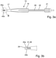
- Figures 1a to 4e show an embodiment of the device 10 in which the light receiving device 24 looks obliquely towards a flat side 50b of the working section 15a of the electrode 15, i.e. the flat side 50b is inclined towards the light input 31, the light input 31 of the light receiving device 24 can also face a narrow side (narrow side or edge) 50d of a spatula-shaped working section 15a of an electrode 15.
- a relative position of the working section 15a of the electrode 15 and the light receiving device 24 is shown in Figure 5a shown using an example.
- the central axis MA of the light acceptance cone 47 is aligned at an acute angle to the longitudinal axis ELA of the electrode 15.
- Figure 5b shows another example in which the light receiving device 24 is arranged in such a position relative to the electrode 15 that the central axis MA of the light acceptance cone 47 is perpendicular to the longitudinal axis ELA of the electrode 15.
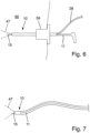
- Figure 6 shows an embodiment of a device 10 for attaching the light receiving device 24, which defines a light acceptance cone 47, for light analysis on an instrument 11 for laparoscopy, which is inserted through a trocar 59 into the abdominal cavity 60.
- the instrument 11 has an electrode 15 which can be fed with electrical RF energy.
- the trocar 59 provides access for the instrument 11 with the connected device 10, wherein the device 10 and the instrument 11 are configured such that, when the device 10 and instrument 11 are inserted, the access remains so tight around the device 10 and the instrument 11 that no gas undesirably escapes from the abdominal cavity 60 through the trocar 59.
- the geometric outer contour is preferably round so that the access through the trocar 59 is correspondingly tight.
- the instrument 11 and the optical fiber 24 can be guided parallel in a tube, e.g., a cladding tube, to avoid mechanical damage.
- the device 10 can, for example, be an adapter that can be attached to the instrument 11 by the user of the instrument 11, and preferably detachable from the instrument 11, or it can be formed on the instrument 11 itself.
- the device 10 is an opening or a channel on the instrument 11, into which an optical fiber 24 can be inserted or clipped as needed.
- Figure 7 shows an embodiment of a device 10 for attaching a light-receiving device 24 for light analysis to an instrument 11 for endoscopic surgery.
- the instrument 11 can be, for example, a flexible probe with an electrode 15, which allows cutting and/or coagulation using an electrode 15 supplied with RF energy, the light phenomena of which can be examined using the light-receiving device 24.
- the instrument 11 can be, for example, an argon plasma coagulation probe.
- the instrument 11 can alternatively or additionally be configured to utilize a dielectric barrier discharge.
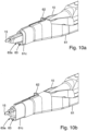
- the Figures 8a to 10b show an example of an embodiment of the device 10, which is configured to be optionally connected to a suction unit 61.
- the suction unit 61 can be connected to the device 10 by the surgeon or his assistant, preferably during the operation.
- the suction unit 61 can preferably be pushed onto the device 10, for example when the device 10 is connected to the instrument 11.
- the suction unit 61 can preferably be connected to the device 10 without tools and can be detached from the device 10 without destruction.
- the suction unit 61 can have a proximal section 61a, which is flexibly elastically connected to the distal section 61b and which must first be bent away to connect the suction unit and the device.
- the device 10 together with the distal section 61b can be positively connected. fixed in the suction unit 61.
- the suction unit 61 has an extension section 61c, which is guided telescopically in the distal section 61b and can be moved from a proximal position (in Figure 10a shown) by advancing a slider section 62 in the distal direction if necessary into a distal position (in Figure 10b shown) can be advanced.
- the suction unit 61 can be transparent at its distal end to provide an improved view of the surgical site.
- the suction unit 61 or, if present, at least the extension section 61c is made of transparent plastic.
- both the suction unit 61 and the device 10 are transparent at their distal ends.
- the suction unit 61 can also be an inseparable part of the device 10.
- the suction unit 61 serves to extract smoke from the surgical site during HF surgery.
- the suction unit 61 has a suction channel 63, which in the illustrated embodiment through the distal section 61b and the extension section 61c to a suction opening 63a at the distal end of the suction unit 61.
- the electrical line 68 for supplying the electrode 15 with RF power (RF supply line)
- the line for the rinsing medium and the suction line 64 in Figures 8a to 8b are shown next to each other brought up to the handle 12, the device 10 and the suction unit 61, for example, the line 28 for the rinsing medium, which preferably also contains the optical fiber 24, can be arranged proximal to the handle 12 within the suction line 64.
- the suction opening 63a is preferably set back proximally relative to the opening of the rinsing channel 58a in every position of the extension section 61c.
- the opening of the rinsing channel 58a is, for example, the opening of the channel section 58 at the distal end of the device 10.
- the opening area of the opening 58a of the rinsing channel 58 at the distal end 29 of the device 10 and/or the opening area of the opening 28a of the line 28 for the rinsing medium at its distal end 32 is smaller than the free opening area of the suction opening 63a of the suction channel.
- the system can be designed or adjusted such that the suction volume flow (e.g. 50 - 120 l/min) into the suction channel is, for example, at least ten times greater than the rinsing volume flow (e.g. approximately 1 l/min) from the rinsing channel 58.
- the suction volume flow e.g. 50 - 120 l/min
- the rinsing volume flow e.g. approximately 1 l/min
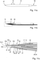
- the free opening area of the suction opening 63a of the suction channel 63 surrounds the electrode 15 and the part of the device 10 at the distal end 29 in which the rinsing channel 58 and the light receiving device 24 are arranged, which extend through the suction opening 63a of the suction channel 63.
- the suction opening 63a may be arranged closer to the distal end of the electrode 15 than the mouth 58a of the irrigation channel 58.
- Such an embodiment is shown in the Figures 13 and 14 illustrated.
- other flow rates for the purging medium or the suction can be used.
- the suction flow rate can be approximately 6-8 times greater than the flow rate of the purging medium or purge gas.
- the suction flow rate can be 50 l/min, and the purging medium flow rate can be approximately 7.0 l/min.
- the device 10 can define a discrete selection of possible positions of the light receiving device 24 relative to the applicator 11. If the applicator 11 defines a discrete selection of possible positions of the electrode 15 relative to the handle 12, the device 10, mediated by the handle 12, defines a discrete number of possible positions of the light receiving device 24 relative to the electrode 15. All positions of the selection are characterized by the fact that it is ensured (if the device 10, instrument 11, and light receiving device 24 are intended for one another) that a sufficient amount of light of the light phenomenon caused by the instrument 11 can be recorded by the light receiving device 24.
- the position (0° position) shown in Figure 8a differs from the position (90° position) according to Figure 8b by a different rotational orientation (rotated by 90°) of the device 10 and thus of the light receiving unit 24 around the longitudinal axis ELA of the electrode 15.
- the discrete layers can, for example, be connected by form-fitting in the direction of rotation around the longitudinal axis ELA of the electrode 15 with structures 56, 57 as in Figure 4e
- the instrument 11, shown in the Figures 8a and 8b is preferably constructed like the instrument 11 according to Figures 4a to 4d . Only the orientation of the electrode 15 is such that in the 0° position, the light receiving device 24 looks at a narrow side 50d of the electrode 15.
- the light receiving device 24 looks correspondingly at the flat side 50b of the spatula-shaped electrode 15.
- the surgeon can thus select during the operation whether the light receiving device 24 should look directly at an edge 50d, 50e of the spatula-shaped electrode 15 ( Figure 8a ) or whether the light receiving device 24 can capture light from both edges 50d, 50e approximately equally should ( Figure 8b ).
- the latter may be advantageous if the surgeon wishes to use both edges 50d, 50e for working.
- the former may be advantageous if the surgeon wishes to work only on the edge 50d toward which the light receiving device 24 is aligned, since the latter can then receive more light from the edge 50d than from the opposite edge 50c.
- the electrode 15 is carried by the device 10 (see the longitudinal sectional views in the Figures 11b and 11c ) without the device 10 having to be connected to the handle 12.
- the device 10 in particular determines the position of the light receiving device 24 relative to the electrode 15, except for, for example, those in which the light receiving device 24 faces a flat side 50b or 50d of the electrode 15 - or alternatively, except for those in which the light receiving device 24 faces an edge 50d, 50e of the electrode 15.
- the device 10 can determine a single possible position of the electrode 15 relative to the light receiving device 24.
- the working section 15a of the electrode 15 is received in an electrode receiving shaft 14, which is received in a receiving recess 35.
- the position of the electrode receiving shaft 14 and thus of the electrode 15 relative to the device 10 and thus to the optical fiber 24 can be fixed via a coupling element 65.
- the electrode receiving shaft 14, which can be a single or multi-part element, can have a form-fitting structure 66 for mechanically and electrically coupling the handle 12 to the electrode receiving shaft 14.
- the handle 12 is in Figure 11a shown in side view as a separate instrument component.
- the assembly of the device 10 and the handle 12 can, as described above, take place during the operation, with the difference that a functional instrument 11 is created from the handle 12 and electrode 15 during assembly.
- the electrode receiving shaft 14, in which the electrode 15 is received is pushed into a receptacle 67 of the handle 12 and fixed, for example, by means of the form-fitting structure 66.
- the electrode receiving shaft 14 is preferably electrically connected to the HF supply lines 68 to the handle 12. The electrode 15 can then be supplied with electrical energy via the electrode receiving shaft 14.
- Embodiments of the embodiment according to Figures 11a to 11c may allow the handle 12 and the device 10 to be adjusted accordingly Figures 8a and 8b can be combined with one another in positions offset by 90°, for example, without changing the relative position of the light receiving device 24 and the electrode 15 (e.g. light receiving device 24 looks at the flat side 50b of the electrode 15).
- the Figures 12a to 12b show a handle 12 coupled to a device 10 according to the invention.
- An extension element 70 is arranged between the handle 12 and the distal end of the device 10 and is accommodated in the device 10.
- the extension element 70 mechanically couples the handle 12 to the device 10 and the RF supply line 68 to the electrode. 15 electrically via a lead piece 71.
- the electrode 15 can be carried by the extension element 70 or the device 10.
- the above explanations can be used for embodiments in which the electrode 15 is carried by an instrument component, e.g., the handle 12, of the instrument 11.
- the above explanations can be used for embodiments in which the electrode 15 is carried by the device 10.
- a device 10 according to the invention is provided for fastening, by the user of a surgical instrument 11, a light-receiving device 24 for light analysis to the instrument 11 or to an instrument component 12 of the instrument 11.
- the device 10 is preferably configured to releasably fix the light-receiving device 24 to the instrument 11 or the instrument component 12.
- the device 10 is preferably designed so that the device 10 can be repeatedly detached and used repeatedly.
- the instrument can be a handle 12 with an electrode 15.
- Embodiments of the device 10 have both a light-receiving device 24 and an electrode 15 fixed relative thereto, wherein the device 10 can be fixed to the handle 12. Embodiments are possible in which the electrode 15 is not carried by the device 10, but by the instrument 11.
- the electrode 15 is removed from the device 10 in a non-destructive manner. detachable or permanently installed in the device 10 part of the device 10. Embodiments are preferred in which the device 10 can be attached (and preferably detached again) to the instrument 11 or the instrument component 12 by the surgical user or their assistant and forms an adapter for attaching a light receiving device 24 to the instrument 11 or the instrument component 12. In other embodiments, the device 10 is formed on the instrument 11, for example, a channel in the instrument 11 into which an optical fiber 24 can be inserted.
- rotation or displacement of the light receiving device 24 relative to the electrode 15 is restricted such that the distal end of the electrode 15 and/or the light phenomena caused by the application of high-frequency electrical energy to the electrode 15 during use of the instrument 11 always remain within the light acceptance cone 47 of the light receiving device 24.
- the shape of a first receptacle 25 of the device 10 is matched to the shape of the instrument 11 in order to predetermine the relative position of the light receiving device 24 relative to the electrode 15, except for such relative positions, such that the tip or the distal end 50 of the electrode 15 and/or the light phenomena caused by the application of high-frequency electrical energy to the electrode 15 during use of the instrument 11 are in every remaining position within the light acceptance cone 47 of the light receiving device 24.
Landscapes
- Health & Medical Sciences (AREA)
- Life Sciences & Earth Sciences (AREA)
- Surgery (AREA)
- Engineering & Computer Science (AREA)
- Veterinary Medicine (AREA)
- General Health & Medical Sciences (AREA)
- Public Health (AREA)
- Animal Behavior & Ethology (AREA)
- Biomedical Technology (AREA)
- Heart & Thoracic Surgery (AREA)
- Medical Informatics (AREA)
- Molecular Biology (AREA)
- Physics & Mathematics (AREA)
- Nuclear Medicine, Radiotherapy & Molecular Imaging (AREA)
- Otolaryngology (AREA)
- Plasma & Fusion (AREA)
- Pathology (AREA)
- Biophysics (AREA)
- Spectroscopy & Molecular Physics (AREA)
- Oral & Maxillofacial Surgery (AREA)
- Cardiology (AREA)
- Surgical Instruments (AREA)
Description
- Die vorliegende Offenbarung betrifft das Gebiet der Analyse von Lichterscheinungen, z.B. Funken, welche HFchirurgische Instrumente hervorrufen können.
-
US 2018/0078301 A1 beschreibt ein elektrochirurgisches Instrument mit einer Beleuchtung. Dadurch soll die Verwendung des elektrochirurgischen Instruments in dunklen Öffnungen verbessert werden. - Aus
DE 197 35 150 A1 ist eine Zusatzvorrichtung für ein Endoskop bekannt, um Fluoreszenzlicht und/oder remittiertes Licht zu erfassen. Im Endoskoprohr ist ein bildgebender Kanal sowie ein Beleuchtungskanal zusätzlich zum Arbeitskanal vorhanden. Eine optische Zusatzvorrichtung leitet emittiertes Fluoreszenzlicht und/oder remittiertes Licht zu einem Spektrometer. An das Spektrometer kann ein Monitor zur Darstellung der Spektren angeschlossen sein. - In den Anmeldungen
EP 3 284 430 A1 undEP 2 659 846 A1 ist ein Instrument mit einer Elektrode und Lichtaufnahmeeinrichtungen offenbart, die mit unterschiedlicher Ausrichtung auf die Elektrode schauend ausgerichtet sein können. -
US 2009/0088772 A1 zeigt ein von einem Roboter tragbares Instrument, welches einen distalen Arbeitsabschnitt und eine optische Faser aufweist, welche Licht zur Analyse des Lichtes von dem distalen Ende des Instruments übertragen kann. - In
EP 2 815 713 A1 ist ein Lichtleiter in einer Elektrode angeordnet. - Um das Licht einer Lichterscheinung, insbesondere eines HF-Funkens, hervorgerufen durch einen HFchirurgischen Eingriff im klinischen Einsatz zu analysieren, werden als Lichtaufnahmeeinrichtung optische Fasern eingesetzt, die mit einer Analyseeinrichtung zur Bestimmung von Lichtmerkmalen verbunden ist und dem Anwender während dem Eingriff Information zum biologischen Gewebe wiedergeben kann. Durch Blut, Gewebeflüssigkeit, Rauchgas (Aerosol), durch Gewebekontakt des distalen Endes der optischen Faser sowie Kontakt der optischen Faser zum Gewebe, durch Abplatzen des Gewebes und Wegspritzen von Gewebepartikeln kann die optische Faser verschmutzen und so die Transmission des Lichtes zur Ausführeinheit merklich reduzieren oder sogar ganz verhindern. Auch durch Anhaften von Gewebe am distalen Ende der Analyseeinrichtung, was indirekt zur Abschattung der optischen Faser führen kann, ist eine Reduktion der Transmission des Lichtes möglich. Eine Verschmutzung der optischen Faser kann das Lichtsignal in seiner Intensität verfälschen, da das Licht von der Verschmutzung unterschiedlich stark absorbiert werden kann. Auch eine Kondensation von Flüssigkeit auf der Faser kann die Transmission kurzzeitig verändern. Durch Verschmutzung kann die Transmission auch wellenlängenabhängig verändert werden, was zu einer Verfälschung des Analyseergebnisses führen kann. Durch einen hohen Energieeintrag (zum Beispiel 300 Watt) bei der HF-Chirurgie können sehr hohe Temperaturen (zum Beispiel größer 300°C) an der Spitze der HF-Elektrode entstehen. Auch hohe Temperaturen können die optische Faser thermisch schädigen, wodurch ebenfalls die Transmission des Lichtes reduziert oder ganz verhindert werden kann.
- Aufgabe der vorliegenden Erfindung ist es, ein verbessertes Konzept für eine Lichtaufnahmeeinrichtung anzugeben.
- Diese Aufgabe wird mit einer Vorrichtung gemäß Anspruch 1 und mit einem Verfahren gemäß Anspruch 15 gelöst.
- Die erfindungsgemäße Vorrichtung ist dazu eingerichtet, bevorzugt lösbar und insbesondere zerstörungsfrei lösbar an einem chirurgischen Instrument, insbesondere einem elektrochirurgischen Instrument, oder an einer Instrumentenkomponente des chirurgischen Instruments befestigt zu werden. Die Vorrichtung weist eine Lichtaufnahmeeinrichtung (insbesondere optische Faser) zur Lichtanalyse auf, insbesondere durch einen medizinisch geschulten Anwender, beispielsweise einen Arzt. Die Befestigung kann während einer Operation (im Operationssaal) erfolgen, beispielsweise nachdem mit dem Instrument ein Operationsschritt durchgeführt wurde. Die Vorrichtung ermöglicht mittels der Lichtaufnahmeeinrichtung (insbesondere optische Faser) das Aufnehmen bzw. Empfangen von Licht, das bei der Verwendung des chirurgischen Instruments erzeugt wird. Das empfangene Licht kann mittels der Lichtaufnahmeeinrichtung zur Lichtanalyse weitergeleitet werden. .Die Lichtaufnahmeeinheit der Vorrichtung kann also bei der Verwendung des Instruments für die Lichtanalyse geeignet Licht aufnehmen.
- Mittels der Vorrichtung kann die Lichtaufnahmeeinrichtung beispielsweise nur dann an einem Handgriff des Instruments befestigt werden, wenn die Gewinnung eine Gewebeinformation durch Lichtanalyse klinisch gewünscht ist. Mit bevorzugten Ausführungsformen zur lösbaren Befestigung kann die Lichtaufnahmeeinrichtung von dem Anwender leicht durch eine neue, saubere Lichtaufnahmeeinrichtung ausgetauscht werden. Die Vorrichtung muss dafür bevorzugt nicht zerstört werden. Die Verbindung der Lichtaufnahmeeinrichtung mit dem chirurgischen Instrument mittels der Vorrichtung ist bevorzugt werkzeuglos möglich. Die Vorrichtung kann vorzugsweise auf das Instrument gesteckt oder, zumindest abschnittsweise, in das Instrument geschoben werden und/oder das Instrument kann vorzugsweise in die Vorrichtung gesteckt oder, zumindest abschnittsweise, in die Vorrichtung geschoben werden und/oder die Vorrichtung kann in das Instrument gesteckt oder, zumindest abschnittsweise, geschoben werden.
- Erfindungsgemäß wird ein Verfahren offenbart, welches das Befestigen einer Lichtaufnahmeeinrichtung an einem chirurgischen Instrument oder einer Instrumentenkomponente des chirurgischen Instruments durch den Chirurgen oder seinen Assistenten während einer Operation aufweist. Der Chirurg oder sein Assistent kombiniert die Lichtaufnahmeeinrichtung mit dem Instrument oder der Instrumentenkomponente zu einer arbeitsfähigen Einheit, mittels welcher in Ausführungsformen insbesondere ein HF-chirurgischer Eingriff unter Überwachung mittels optischer Emissionsspektroskopie durchgeführt werden kann. Der Chirurg oder sein Assistent kann dazu beispielsweise eine erfindungsgemäße Vorrichtung wie hierin beschrieben verwenden.
- Die erfindungsgemäße Vorrichtung kann beispielsweise durch wenigstens eines oder mehrere der nachfolgend angegebenen Merkmale weitergebildet werden.
- Die Instrumentenkomponente des chirurgischen Instruments kann beispielsweise ein Bauteil oder eine Baugruppe des Instruments sein.
- Bevorzugt ist die Vorrichtung zur Befestigung, während einer Operation (im Operationssaal), beispielsweise nachdem mit dem Instrument ein Operationsschritt durchgeführt wurde, einer Lichtaufnahmeeinrichtung (insbesondere optische Faser) zur Lichtanalyse an einem arbeitsfähigen chirurgischen Instrument durch einen medizinisch geschulten Anwender, beispielsweise einen Arzt eingerichtet. Das Instrument ist in Ausführungsformen also bereits ohne die Vorrichtung und die Lichtaufnahmeeinrichtung arbeitsfähig, wenn die Lichtaufnahmeeinrichtung mittels der Vorrichtung an dem Instrument befestigt wird. Die Instrumentenkomponente kann beispielsweise bereits vor dem Verbinden mit der Vorrichtung mit einer Elektrode verbunden sein, so dass die Instrumentenkomponente mit der Elektrode ein arbeitsfähiges HF-chirurgisches Instrument bildet.
- Alternativ oder zusätzlich ist die Vorrichtung bevorzugt dazu eingerichtet, die Instrumentenkomponente beim Befestigen der Lichtaufnahmeeinrichtung an der Instrumentenkomponente zu einem arbeitsfähigen Instrument zu ergänzen. Die Vorrichtung kann beispielsweise dazu eingerichtet sein, eine Elektrode zu tragen.
- Insbesondere wenn die Vorrichtung eine Elektrode und eine Lichtaufnahmeeinrichtung aufweist, aber auch bei anderen Ausführungsformen, ist es bevorzugt, wenn die Vorrichtung derart eingerichtet ist, die räumliche Relativlage (Relativposition und/oder Relativausrichtung) der Elektrode und der Lichtaufnahmeeinrichtung relativ zueinander vorzugeben. Dabei kann nur eine einzige Relativposition und/oder Relativausrichtung ermöglicht werden oder es kann eine Relativposition und/oder Relativausrichtung aus mehreren möglichen Relativpositionen und/oder Relativausrichtungen auswählbar sein. Dabei kann zum Beispiel mindestens ein oder genau ein einziger Freiheitsgrad der Relativposition und/oder Relativausrichtung veränderbar sein. Damit können eine einzige oder mehrere Relativpositionen und/oder Relativausrichtungen zwischen der Lichtaufnahmeeinrichtung und der Elektrode vorgegeben werden. Beispielsweise kann die Elektrode in mehreren unterschiedlichen Drehlagen um ihre Längsachse an der Vorrichtung angeordnet werden.
- Wenn die Elektrode beispielsweise eine Spatelelektrode ist, bei welcher zwischen zwei seitlichen Kanten auf gegenüberliegenden Seiten Spatelflächen angeordnet sind, können sich die eine oder die mehreren festgelegten Ausrichtungen von ausgeschlossenen Ausrichtungen dadurch unterscheiden, dass die Lichtaufnahmeeinrichtung beispielsweise in jeder der Ausrichtungen auf jeweils eine Spatelfläche oder in der einzigen Ausrichtung auf eine Spatelfläche schräg ausgerichtet ist. Die Vorrichtung kann mit einem Handgriff verbindbar sein und dazu eingerichtet sein, so den Handgriff zu einem mittels der Elektrode, welche in die Vorrichtung integriert ist oder eine eigenständige Komponente darstellt, arbeitsfähigen Instrument zu ergänzen. Der Handgriff ist bevorzugt mit einer Elektrode auch zu einem arbeitsfähigen Instrument ergänzbar, ohne die Lichtaufnahmeeinrichtung mittels der Vorrichtung an dem Instrument befestigen zu müssen. Die Instrumentenkomponente, beispielsweise der Handgriff, selbst ist folglich bevorzugt dazu eingerichtet, eine Elektrode zu tragen.
- Die Vorrichtung legt bevorzugt eine vorbestimmte diskrete, z.B. diskrete Werte und/oder voneinander getrennte Bereiche, und/oder, zumindest bereichsweise, kontinuierliche Auswahl an möglichen räumlichen Relativlagen der befestigten Lichtaufnahmeeinrichtung relativ zu dem Instrument fest. Alle Relativlagen der Auswahl zeichnen sich dadurch aus, dass sichergestellt ist (wenn Vorrichtung, Instrument und Lichtaufnahmeeinrichtung für einander bestimmt sind), dass eine ausreichende Lichtmenge der Lichterscheinung (z.B. ein Funke oder ein fortwährend aufrechterhaltenes Plasma) hervorgerufen durch das Instrument von der Lichtaufnahmeeinrichtung aufnehmbar ist. Dadurch kann sichergestellt werden, dass der Arzt oder sein Assistent die Lichtaufnahmeeinrichtung stets lagerichtig am Instrument befestigt, so dass eine ausreichende Lichtmenge von der Lichtaufnahmeeinrichtung aufgenommen wird, um eine aussagekräftige Lichtanalyse zu gewährleisten. Die Auswahl kann eine einzige mögliche Relativlage oder mehrere mögliche Relativlagen einschließen. Die räumliche Relativlage wird durch die Position und Orientierung der Lichtaufnahmeeinrichtung, insbesondere des Lichteingangs der Lichtaufnahmeeinrichtung, relativ zu dem Instrument oder der Instrumentenkomponente des Instruments, beispielsweise der Elektrode oder dem Handgriff, bestimmt.
- Die Auswahl kann eine diskrete Auswahl möglicher Relativlagen und/oder eine nicht-diskrete (kontinuierliche) Auswahl möglicher Relativlagen einschließen. Ausführungsformen sind möglich, in denen die Vorrichtung nur eine diskrete Auswahl einer endlichen Anzahl an vorgegebenen Relativlagen erlaubt. Alternativ sind Ausführungsformen möglich, in denen die Vorrichtung keine diskrete Unterauswahl festlegt, sondern eine nicht-diskrete Auswahl oder Einstellung von Relativlagen möglich ist. Eine nicht-diskrete Auswahl möglicher Relativlagen bedeutet insbesondere, dass der Anwender aus einer aktuellen Relativlage heraus die Relativlage verändern kann - und zwar über Spiel innerhalb der aktuellen Relativlage hinaus. Im Zuge dessen können kontinuierlich weitere mögliche Relativlagen durchlaufen werden.
- Die räumliche Relativlage der befestigen Lichtaufnahmeeinrichtung wird relativ zu dem Instrument mittels der Vorrichtung vorzugsweise vollständig festgelegt (Relativlage einer diskreten Auswahl oder Unterauswahl an einer oder mehreren Relativlagen) oder beispielsweise bis auf einen oder zwei Freiheitsgrade (Relativlage in einer kontinuierlichen Unterauswahl möglicher Relativlagen). Die Vorrichtung kann die räumliche Relativlage beispielsweise bis auf einen oder zwei Winkel festlegen. Der Freiheitsgrad oder einer der Freiheitsgrade, die nicht oder nur bis auf eine Auswahl eines Wertebereichs festgelegt sind, kann beispielsweise der Winkel der Lichtaufnahme um das Instrument, beispielweise um eine Elektrode des Instruments, herum sein. Die Vorrichtung kann die räumliche Relativlage beispielsweise vollständig festlegen (nur eine einzige Relativlage ist möglich), wobei dies ein geringfügiges Spiel des Instruments in der oder bezüglich der Vorrichtung, beispielsweise in einer Längsrichtung des Instruments oder der Vorrichtung, einer Radialrichtung und/oder einer Drehrichtung, einbeziehen kann, welches die Lichtanalyse nicht beeinträchtigt. Jedenfalls aber wird eine Beweglichkeit der Lichtaufnahmeeinrichtung relativ zu dem Instrument, beispielsweise relativ zu einer Elektrode des Instruments, mittels der Vorrichtung derart eingeschränkt, dass in allen verbleibenden Lagen der Lichtaufnahmeeinrichtung relativ zu dem Instrument, beispielsweise relativ zu der Elektrode, eine zuverlässige Lichtaufnahme aus dem Bereich, in welchem die Funken und/oder das Plasma auf Grund der Einwirkung des Instruments entsteht, durch die Lichtaufnahmeeinrichtung gewährleistet ist. Bevorzugt umfasst oder umschließt der Lichtakzeptanzkegel in allen Lagen, welche die Vorrichtung der Lichtaufnahmeeinrichtung und dem Instrument relativ zueinander ermöglicht, den Bereich, in welchem die Lichterscheinungen erzeugt werden.
- Mit Ausführungsformen der erfindungsgemäßen Vorrichtung kann eine Lichtaufnahmeeinrichtung an einem Instrument für die offene Chirurgie, zum Beispiel einem HF-Handgriff mit einer HF-Elektrode (auch (HF-)Applikator genannt), einem Instrument für die Laparoskopie oder einem Instrument für die flexible Endoskopie, wie zum Beispiel flexible Sonden für die Argon-Plasma-Koagulation, verwendet werden.
- Wenn die Vorrichtung eine vorbestimmte Auswahl an räumlichen Relativlagen der befestigten Lichtaufnahmeeinrichtung relativ zu dem Instrument festlegt, ist eine Fehlausrichtung der Lichtaufnahmeeinrichtung durch den Anwender des Instruments ausgeschlossen, der als Arzt im medizinischen Gebrauch des Instruments geschult ist, nicht jedoch im Auffinden einer Lage der Lichtaufnahmeeinrichtung relativ zu dem Instrument, so dass die Lichtaufnahmeeinrichtung arbeiten kann. Ein Eingriff des Arztes mittels eines HFchirurgischen Instruments kann beispielsweise zunächst das Eröffnen und Freilegen des OP-Situs mittels eines HFchirurgischen Schneidinstruments bedeuten und danach die Präparation für die Gewebedifferenzierung. Beim Eröffnen und Freilegen des OP-Situs können teils Einstellungen der elektrischen Parameter für Schneiden erforderlich sein, welche eine effiziente Blutstillung möglich machen, aber auch eine große thermische Schädigung. Bei der Gewebedifferenzierung wird dagegen nur eine geringere thermische Schädigung akzeptiert. Auch kann sich die Elektrodenform unterscheiden, welche der Chirurg zum Eröffnen und Freilegen und zum Gewebedifferenzieren einsetzt. Die thermische Schädigung des Gewebes (höherer Energieeintrag) korreliert mit der Verschmutzung der optischen Faser am distalen Ende. Mit Ausführungsformen der erfindungsgemäßen Vorrichtung kann der Chirurg die Lichtaufnahmeeinrichtung mittels der Vorrichtung erst dann am Handgriff befestigen, wenn die Schritte der Eröffnung und Freilegen des OP-Situs abgeschlossen sind. Wenn für die anschließende Gewebedifferenzierung eine Einstellung des Instruments mit geringerer thermischer Schädigung erforderlich ist, ist die Gefahr des Verschmutzens des Lichteingangs vermindert.
- Bevorzugt weist das Instrument eine mit HF-Energie beaufschlagbare Elektrode auf, so dass das Instrument unabhängig von der Vorrichtung für einen HFchirurgischen Eingriff verwendet werden kann. Die Elektrode des Instruments, beispielsweise des HF-Applikators, kann austauschbar sein. Das Instrument kann beispielsweise ein HF-Applikator mit einem Handgriff sein, welcher eine Elektrode aufweist. Die Elektrode kann an dem Handgriff austauschbar befestigbar sein. Der Handgriff kann die Position und Orientierung der Elektrode bis auf eine einzige oder eine diskrete Auswahl von Möglichkeiten in Bezug auf den Handgriff zu lassen. Alternativ oder zusätzlich kann die Vorrichtung beispielsweise sowohl die Lichtaufnahmeeinrichtung als auch eine Elektrode aufweisen.
- Die Vorrichtung ist bevorzugt dazu eingerichtet eine räumliche Relativlage der befestigten Lichtaufnahmeeinrichtung relativ zu dem Instrument festzulegen, indem die Vorrichtung eine vorbestimmte Auswahl an räumlichen Relativlagen der befestigten Lichtaufnahmeeinrichtung relativ zu der Elektrode festlegt. Die Vorrichtung kann dazu eingerichtet sein, eine kontinuierliche oder diskrete Auswahl möglicher Lagen der Lichtaufnahmeeinrichtung relativ zu der Elektrode festzulegen. Die Vorrichtung kann dazu eingerichtet sein, eine einzige mögliche räumliche Relativlage für die befestigte Lichtaufnahmeeinrichtung relativ zu der Elektrode festzulegen. Durch die Festlegung einer Auswahl an möglichen Relativlagen soll Orientierung und Abstand der Lichtaufnahmeeinrichtung relativ zu einem Bereich an der Elektrode festgelegt werden, in welchem das Instrument mittels der Elektrode Lichterscheinungen erzeugt. Wenn die Orientierung und der Abstand der Lichtaufnahmeeinrichtung, insbesondere des Lichteingangs der Lichtaufnahmeeinrichtung, relativ zu der Elektrode vorbestimmt festgelegt ist, kann eine bestimmte Aussagekraft und Qualität der Lichtanalyse mittels der Lichtaufnahmeeinrichtung sichergestellt werden.
- Die Vorrichtung weist bevorzugt eine Aufnahme auf, welche die Beweglichkeit des Instruments in der Aufnahme auf eine Beweglichkeit in eine Richtung, insbesondere eine Axialrichtung des Instruments, der Elektrode, der Aufnahme und/oder der Vorrichtung, einschränkt. Bevorzugt legt die Vorrichtung mittels der Aufnahme fest, dass das Instrument beim Befestigen in der Richtung, insbesondere Axialrichtung, in die Aufnahme einzuführen ist. Die Aufnahme kann dazu eingerichtet sein, die Bewegung des Instruments oder der Instrumentenkomponente in Axialrichtung in Richtung zum distalen Ende der Vorrichtung hin zu begrenzen.
- Die Vorrichtung weist bevorzugt eine Einrichtung zum anschließenden Fixieren der axialen Position des Instruments in der Aufnahme auf, bis höchstens auf ein axiales Spiel, welches die Lichtanalyse nicht beeinträchtig, z.B. weil die Spitze der Elektrode trotz des Spiels stets in einem Lichtakzeptanzkegel der Lichtaufnahmeeinrichtung bleibt. Die Einrichtung zum anschließenden Fixieren kann dazu eingerichtet sein, die Bewegung des Instruments oder der Instrumentenkomponente in Axialrichtung in Richtung vom distalen Ende der Vorrichtung weg zu begrenzen.
- Die Einrichtung zum anschließenden Fixieren der axialen Position weist bevorzugt einen Abschnitt auf, welcher seitlich relativ zur Axialrichtung des Instruments und/oder der Vorrichtung und/oder der Elektrode im Zuge der Befestigung der Lichtaufnahmeeinrichtung an dem Instrument beweglich ist. Dieser bewegliche Abschnitt ist bevorzugt dazu eingerichtet, nach dem Anordnen des Instruments in der Aufnahme durch seitliche Bewegung des Abschnitts in Eingriff mit dem Instrument gebracht zu werden, um die axiale Position des Instruments in der Aufnahme zu fixieren. Der bewegliche Abschnitt ist vorzugsweise flexibel mit der übrigen Vorrichtung befestigt, um den Abschnitt seitlich bewegen zu können. Dies wird gegenüber Ausführungsformen bevorzugt, bei denen der bewegliche Abschnitt an einem weiteren Abschnitt des Instruments angelenkt bzw. anscharniert ist. Bevorzugt ist der Abschnitt elastisch, so dass dieser nach dem Bewegen des Abschnitts gegen eine Federkraft vor dem Anordnen des Instruments in der Vorrichtung auf Grund der Federkraft sich selbstständig wieder in Richtung zu seiner Ausgangslage zurückbewegt. Mit flexiblem Abschnitt kann auf ein Scharnier verzichtet werden, was die Herstellung der Vorrichtung vereinfacht und die Vorrichtung einfacher zu sterilisieren und/oder zu säubern macht.
- Die Vorrichtung weist bevorzugt einen Spülkanal auf, wobei der Spülkanal dazu eingerichtet ist, ein Spülmedium, beispielsweise Kohlenstoffdioxid, Edelgas, Stickstoff oder ein anderes chemisch inertes Gas oder Gasgemisch, bevorzugt laminar, entlang der Lichtaufnahmeeinrichtung an dem Lichteingang der Lichtaufnahmeeinrichtung vorbei auszugeben. Damit kann Verunreinigung des Lichteingangs der Lichtaufnahme verhindert werden, der Lichteingang der Lichtaufnahme gereinigt, Aerosol zwischen Lichteingang und Entstehungsort des Lichtes weggeblasen und/oder das Instrument, insbesondere eine Elektrode, gekühlt werden.
- Bevorzugt ist die Vorrichtung dazu eingerichtet, die räumliche Lage des Spülkanals relativ zu der Lichtaufnahme auf eine, insbesondere diskrete, Auswahl räumlicher Relativlagen oder eine einzige räumliche Relativlage festzulegen. Der Spülfluss ist vorzugsweise in die Richtung ausgerichtet, in welche auch die Lichtaufnahmeeinrichtung bzw. deren Lichteingang schaut, d.h. in die Richtung der Mittelachse des Lichtakzeptanzkegels. In Ausführungsformen kann der Spülfluss an dem Lichteingang oder zwischen dem Lichteingang und dem Einwirkungsbereich der HF-Elektrode schräg auch bis 90° Grad zur optischen Achse, zum Beispiel durch eine Prallplatte oder durch eine einseitige Erhebung im Strömungskanal abgelenkt werden, um als Partikelbarriere zu dienen.
- Bei zu starkem Strom an Spülmedium kann damit Gewebe verdrängt werden. Für eine hohe Präzision ist dies insbesondere bei der Präparation, also der präzisen Freistellung oder Freilegung von anatomischen Strukturen zu vermeiden. Andererseits soll der Volumenstrom an Spülmedium ausreichen, um Verschmutzung des Lichteingangs zuverlässig zu vermeiden und/oder um für eine ausreichende Kühlung der Elektrode zu sorgen. Des Weiteren können mit ausreichender Strömung gasförmige oder flüssige Medien beispielhaft Rauchgas, Blut oder flüssiges Fett verdrängt werden. Bei festgelegter räumlicher Lage des Spülkanals relativ zu der Lichtaufnahmeeinrichtung, insbesondere deren Lichteingang, kann mit genau abgestimmtem Volumenstrom an Spülmedium gearbeitet werden, welcher nicht zu einer präzisionsvermindernden Gewebeverdrängung führt, aber zu einer zuverlässigen Fernhaltung zu Verunreinigungen von dem Lichteingang und/oder Verdrängung von lichtaufnahmestörenden Medien und/oder Kühlung.
- Vorzugsweise ist der Lichteingang der Lichtaufnahme in der Vorrichtung angeordnet, um Schutz des Lichteingangs vor Verschmutzungen zu bieten. Die Vorrichtung kann dadurch den Lichteingang gegen aus bestimmten Winkeln eintreffende Flüssigkeitstropfen oder Partikel abschirmen, ohne den Lichteinfall in den Lichteingang aus anderen Winkeln zu beeinträchtigen. In Ausführungsformen mit einem Spülkanal innerhalb der Vorrichtung kann der Lichteingang beispielsweise innerhalb des Spülkanals angeordnet sein bzw. die Lichtaufnahmeeinrichtung in dem Spülkanal enden.
- Die Lichtaufnahme kann in Ausführungsformen mit Spülkanal beispielsweise innerhalb des Spülkanals oder durch den Spülkanal verlaufen. Gleichzeitig ist die Lichtaufnahmeeinrichtung bevorzugt innerhalb der Vorrichtung in einer einzigen bestimmten räumlichen Lage fixiert.
- Eine besonders kompakte Bauform kann erhalten werden, wenn die Lichtaufnahmeeinrichtung - zum Beispiel ein gerader Endabschnitt der Lichtaufnahmeeinrichtung, welcher an den Lichteingang angrenzen kann - und/oder die optische Achse der Lichtaufnahmeeinrichtung und/oder die Mittelachse des Lichtakzeptanzkegels der Lichtaufnahmeeinrichtung und die Elektrode einen spitzen Winkel, beispielsweise kleiner 15°, einschließen.
- In Ausführungsformen der Vorrichtung ist - bei hergestellter Verbindung zwischen der Vorrichtung und dem Instrument - bevorzugt ein Kanalabschnitt des Spülkanals ausgebildet, welcher einerseits von einer Wand der Vorrichtung und andererseits von einer ersten Längsseite einer Elektrode und/oder eines Elektrodenschafts der Vorrichtung begrenzt ist. Der Kanalabschnitt ist von Spülmedium durchströmbar. Eine der ersten Längsseite gegenüberliegende zweite Längsseite der Elektrode und/oder des Elektrodenschafts liegt entlang des Kanals vorzugsweise wenigstens abschnittsweise frei. Während das Spülmedium durch den Kanalabschnitt strömt, kann dieses die Elektrode an der ersten Längsseite kühlen. Die zweite Längsseite liegt frei, hat also insbesondere Kontakt zu der Umgebung der Vorrichtung, insbesondere Luftkontakt oder Kontakt zum gas- oder aerosolförmigen Umgebungsmedium, und kann dadurch genügend Wärme abgeben, so dass sich die Elektrode bei Betrieb insgesamt nicht übermäßig erwärmt. Der Volumenstrom an Spülmedium kann damit auf eine Rate eingestellt werden, die eine ausreichende Kühlung der Elektrode - und bevorzugt auch eine ausreichende Abschirmung und/oder Reinigung des Lichteingangs vor Verschmutzung - gewährleistet.
- Die Lichtaufnahmeeinrichtung, beispielsweise eine optische Faser, erstreckt sich vorzugsweise von dem Lichteingang aus in der und/oder neben der Vorrichtung durchgehend - ohne optische Schnittstelle zwischendurch - proximal über die Vorrichtung hinaus, um Licht zur Analyse weiterzuleiten. Dies ist von Vorteil, da eine optische Schnittstelle verschmutzen kann, wenn an ihr für einen Teil des operativen Eingriffs keine Lichtaufnahme mit Lichteingang angeschlossen wäre.
- Bei dem Instrument kann es sich beispielsweise um ein HF-chirurgisches Schneid-, Koagulations- und/oder Devitalisierungsinstrument handeln. Das Instrument kann beispielsweise dazu eingerichtet sein, mit einem ionisierbaren Gas zu arbeiten, welches in einen Plasmazustand überführt wird. Das Instrument kann insbesondere ein Argon-Plasma-Koagulations (APC)- Instrument sein. Das Instrument kann alternativ oder zusätzlich dazu eingerichtet sein, eine dielektrische Barriereentladung zu nutzen.
- Es wird erfindungsgemäß außerdem eine Anordnung aus einem Instrument und einer erfindungsgemäßen Vorrichtung derart angegeben, dass in der Anordnung mittels der Vorrichtung eine Lichtaufnahmeeinrichtung an dem Instrument befestigt ist.
- Weitere Merkmale und vorteilhafte Ausführungsformen der Vorrichtung und der Anordnung ergeben sich aus der nachfolgenden Beschreibung sowie den Figuren. Es zeigen beispielhaft:
-
Figur 1a - eine perspektivische Darstellung eines Instruments in Form eines HF-Applikators, welcher in einem Ausführungsbeispiel einer erfindungsgemäßen Vorrichtung befestigt angeordnet ist, -
Figur 1b - die erfindungsgemäße Vorrichtung gemäßFigur 1a in einer längsgeschnittenen perspektivischen Ansicht, -
Figur 2a - die beispielhafte erfindungsgemäße Vorrichtung gemäßFiguren 1a und1b in einer seitlichen Ansicht mit ausschnittsweiser Längsschnittdarstellung des distalen Endabschnitts der Vorrichtung, -
Figur 2b - eine Vergrößerung der ausschnittsweisen Längsschnittdarstellung ausFigur 2a (Ausschnitt in Figur 2a mit einem Kreis veranschaulicht), -
Figur 3a - das Ausführungsbeispiel der erfindungsgemäßen Vorrichtung gemäßFiguren 1a und1b in einer Draufsicht, -
Figur 3b - eine ausschnittsweise Draufsicht auf das distale Ende der Vorrichtung gemäßFiguren 1a und1b (Ausschnitt inFigur 3a mit einem Kreis veranschaulicht), -
Figur 4a - eine Seitenansicht des Ausführungsbeispiels des Instruments gemäßFigur 1a in Form eines HF-Applikators, welcher in dem Ausführungsbeispiel der erfindungsgemäßen Vorrichtung gemäßFigur 1a befestigt angeordnet ist, -
Figur 4b - eine Draufsicht des Ausführungsbeispiels des Instruments gemäßFigur 1a befestigt in der Vorrichtung gemäßFigur 1a , -
Figur 4c - eine längsgeschnittene Ansicht des Instruments in der Vorrichtung gemäßFigur 1a , -
Figur 4d - einen Ausschnitt der Längsdarstellung gemäßFigur 4c , -
Figur 4e - eine Ausrichtstruktur und eine Gegenausrichtstruktur, -
Figuren 5a und 5b - stark schematisierte Darstellungen von möglichen relativen Ausrichtungen eines Lichteingangs zu einer Elektrode und -
Figur 6 - ein weiteres Ausführungsbeispiel einer erfindungsgemäßen Vorrichtung mit einem verbundenen Beispiel eines Instruments für die laparoskopische Chirurgie, -
Figur 7 - ein weiteres Ausführungsbeispiel einer erfindungsgemäßen Vorrichtung mit einem verbundenen Beispiel eines Instruments für die endoskopische Chirurgie, -
Figur 8a bis 10b - ein weiteres Ausführungsbeispiel einer erfindungsgemäßen Vorrichtung mit einer Absaugeinheit, -
Figur 11a - ein Handgriffteil eines Instruments, -
Figur 11b - eine erfindungsgemäße Vorrichtung, welche eine Elektrode trägt, -
Figur 11c - einen Ausschnitt der Längsdarstellung gemäßFigur 11b , -
Figur 12a - eine erfindungsgemäße Vorrichtung mit einem Verlängerungselement zwischen einer Elektrode und einem Handgriff in einer perspektivischen Ansicht, -
Figur 12b - die Anordnung gemäßFigur 12a in einer Längsschnittansicht, -
Figur 13 eine perspektivische Teildarstellung in einem Bereich im Anschluss an ein distales Ende eines Instruments, das in einem weiteren Ausführungsbeispiel einer erfindungsgemäßen Vorrichtung angeordnet ist und -
Figur 14 einen Längsschnitt durch den inFigur 13 dargestellten Bereich des Instruments und der Vorrichtung. -
Figur 1a zeigt in einer perspektivischen Ansicht eines Ausführungsbeispiel einer erfindungsgemäßen Vorrichtung 10 in Form eines Handgriffteils, in welchem ein beispielhaftes Instrument 11, hier ein Applikator für die offene Chirurgie, aufgenommen ist. Das Instrument 11 ist bevorzugt ein Instrument zu monopolaren HF-Chirurgie, bei welcher ein Pol der Spannungsquelle an einer großflächigen, am Patienten befestigten sogenannten Neutralelektrode angeschlossen ist (nicht dargestellt). Alternativ kann das Instrument 11 ein Instrument für die bipolare HF-Chirurgie sein. - Der das Instrument 11 darstellende Applikator selbst weist ein Handgriffteil 12 mit Bedienelementen 13 auf. In dem distalen Endabschnitt des Handgriffteils 12 ist ein Elektrodenaufnahmeschaft 14 mit einer Elektrode 15 aufgenommen. Das Handgriffteil 12 ist mit einer elektrischen Leitung 68 verbunden, über welche die Elektrode 15 mit elektrischer Hochfrequenzleistung beaufschlagt werden kann.
- Die Vorrichtung 10 weist einen distalen Abschnitt 17 auf, in welchem der Applikator 11 steckt. Der proximale Endabschnitt 18 des distalen Abschnitts 17 der Vorrichtung 10 weist eine Halbschalenform auf, welche den Applikator 11 aufnimmt. Die Halbschalenform 18 ist an einer Längsseite 19 (Oberseite) offen, um einen Zugang zu den Bedienelementen 13 des Instruments 11 an der Oberseite 20 des Instruments 11 bereitzustellen.
- Die Vorrichtung 10 weist außerdem einen beispielsgemäß halbschalenförmigen proximalen Abschnitt 21 auf. Dieser ist an der Längsseite 19 der Vorrichtung 10 offen, an welcher auch der proximale Endabschnitt 18 offen ist. Der proximale Abschnitt 21 ist über einen flexiblen Übergangsabschnitt 22 mit dem distalen Abschnitt 17 der Vorrichtung 10 verbunden. Die Vorrichtung 10 umschließt den Applikator 11 zumindest abschnittsweise formschlüssig, um die Relativlage einer Lichtleiteinrichtung und/oder Lichtaufnahmeeinrichtung 24 relativ zu dem Applikator 11 festzulegen. Die Lichtleiteinrichtung und/oder Lichtaufnahmeeinrichtung kann insbesondere wenigstens eine optische Faser aufweisen.
- Die Vorrichtung 10 erstreckt sich vom proximalen Ende zum distalen Ende im Wesentlichen in einer Axialrichtung R. Der distale Abschnitt 17 und/oder der proximale Abschnitt 21 können einen sich um eine parallel zur Längsrichtung L erstreckende Krümmungsachse gekrümmten Verlauf aufweisen. Beispielsgemäß hat der Übergangsabschnitt 22 eine Stabform. Der Übergangsabschnitt 22 ist mit dem distalen Abschnitt 17 und/oder dem proximalen Abschnitt 21 an einer zentralen Stelle verbunden, ausgehend von der sich zwei Schalenteile des distalen Abschnitts 17 bzw. des proximalen Abschnitts 21 in entgegengesetzte Richtungen krümmen, um die jeweilige Halbschale zu bilden. Insbesondere bildet der Übergangsabschnitt 22 - im Unterschied zum distalen Abschnitt 17 und zum proximalen Abschnitt 21 - keinen konkaven Aufnahmebereich für den Applikator 11.
- Der distale Abschnitt 17, der Übergangsabschnitt 22 und der proximale Abschnitt 21 bestehen vorzugsweise aus dem gleichen Kunststoff. Der Übergangsabschnitt 22 ist mit dem distalen Abschnitt 17 und dem proximalen Abschnitt 21 vorzugsweise nahtlos einstückig verbunden. Die Vorrichtung 10 kann insbesondere im Spritzgießverfahren hergestellt sein. Die Flexibilität des Übergangsabschnitts 22 verglichen mit dem distalen Abschnitt 17 und/oder dem proximalen Abschnitt 21 ist beispielsgemäß dadurch erreicht, dass der Übergangsabschnitt 22 schlanker als der distale Abschnitt 17 und der proximale Abschnitt 21 ausgebildet ist. Er kann insbesondere in jede Richtung quer zu seiner Erstreckung eine die Flexibilität gewährleistende geringe Dimension aufweisen. Bevorzugt ist die Vorrichtung 10 oder zumindest der distale Abschnitt 17 transparent, um eine verbesserte Sicht auf den OP-Situs zu schaffen.
- Wie insbesondere in
Figuren 1b ,2b und4d veranschaulicht, stellt der distale Abschnitt 17 der Vorrichtung 10 eine kanalartige erste Aufnahme 25 für einen Formschlussabschnitt 26 des Applikators 11 bereit. Die erste Aufnahme 25 (kann auch erster Aufnahmekanal genannt werden) ist vorzugsweise ringsum (in alle Radialrichtungen) geschlossen. Die erste Aufnahme 25 legt mittels Formschluss eine Ausrichtung der Elektrode 15 des Instruments 11 in der Vorrichtung 10 entlang einer Längsachse L der ersten Aufnahme 25 fest. - Die Vorrichtung 10 weist, wie beispielhaft insbesondere auch in den
Figur 2b gezeigt, zudem eine abschnittsweise kanalartige zweite Aufnahme 27 für eine Leitung 28, beispielsweise einen Schlauch oder eine Röhre, auf, durch welche sich die wenigstens eine optische Faser, d.h. eine einzelne optische Faser oder ein Bündel an optischen Fasersträngen, als Lichtaufnahmeeinrichtung 24 in Richtung zu dem distale Ende 29 des distalen Abschnitts 17 der Vorrichtung 10 erstreckt. Die Leitung 28 ist in der zweiten Aufnahme 27 vorzugsweise durch Kraft- und/oder Reibschluss mit der Wandfläche 30 der zweiten Aufnahme 27 gegen Bewegen der Leitung 28 in der zweiten Aufnahme 27 fixiert. Die Leitung 28 bildet einen Leitungskanal (Spülkanal) und dient dem Leiten eines Spülmediums zum Reinigen und/oder Abschirmen eines Lichteingangs 31 der optischen Faser 24. Die optische Faser 24 dient der Aufnahme von Licht aus Lichterscheinungen, welche durch die Elektrode 15 des Applikators 11 erzeugt werden. Die Lage der optischen Faser 24 in der Vorrichtung 10 ist bevorzugt vollständig festgelegt. - Die Leitung 28 verläuft geschützt seitlich neben dem Applikator 11 zwischen dem flexiblen Übergangsabschnitt 22 und dem Applikator 11 durch den halbschalenförmigen proximalen Abschnitt 21 des distalen Abschnitts 17 der Vorrichtung 10.
- Die zweite Aufnahme 27 für die Leitung 28 ist dazu eingerichtet, diese abschnittsweise im Wesentlichen parallel zu dem Applikator 11 in Richtung zu dem distalen Ende 29 der Vorrichtung 10 zu führen. Wie insbesondere in den
Figuren 1b und2b veranschaulicht, ist die zweite Aufnahme 27 ferner dazu eingerichtet, einen an das distale Ende 32 der Leitung 28 angrenzenden Leitungsabschnitt 33 der Leitung 28 in einem spitzen Winkel an die Längsachse L der ersten Aufnahme 25 heranzuführen. Ebenso schließt, wie insbesondereFigur 2b veranschaulicht, der an den Lichteingang 31 der optischen Faser 24 angrenzende Endabschnitt 34 der optischen Faser 24 bzw. dessen optische Achse OA und/oder die Mittelachse MA des Lichtakzeptanzkegels 47 der optischen Faser 24 einen spitzen Winkel W mit der Längsachse L der Aufnahmebohrung 35 der ersten Aufnahme 25 für die Elektrode 15 oder den Elektrodenaufnahmeschaft 14 ein - und damit auch mit der Längsachse ELA der Elektrode 15, welche mit der Längsachse L der ersten Aufnahme 25 zusammenfällt. Der spitze Winkel, in welchem der Leitungsabschnitt 33 an die Längsachse L der ersten Aufnahme 25 herangeführt wird, stimmt bevorzugt mit dem Winkel W zwischen Mittelachse MA des Lichtakzeptanzkegels 47 und der Längsachse ELA der Elektrode 15 überein. - Die optische Faser 24 kann in der Leitung 28 zentriert gehalten sein bzw. im Wesentlichen koaxial deren Verlauf folgen. Dazu können beispielsweise Halteelemente (nicht gezeigt) dienen, die innerhalb der Leitung 28 angeordnet sind, ein Spülmediumfluss durch die Leitung 28 an das distale Ende 29 der Vorrichtung 10 erlauben und gleichzeitig die optische Faser 24 auf Abstand zu der Innenwandfläche 37 der Leitung 28 halten. Alternativ kann die Faser 24 beispielsweise lose in dem Leitungsschlauch 28 liegen, wobei ein Endabschnitt 34 der Faser, wie weiter unten beschrieben, fest mit der Vorrichtung 10 verbunden sein kann. Die optische Faser 24 ist, beispielsweise mittels der Halteelemente, bevorzugt auch gegen Verdrehen der optischen Faser 24 um eine Längsachse der optischen Faser 24 gesichert. Der Volumenstrom an Spülmedium wird im Ausführungsbeispiel im Wesentlichen konzentrisch zur optischen Faser 24 geführt. Alternativ kann der Volumenstrom am distalen Ende 38 der optischen Faser 24 seitlich zugeführt werden. In beiden Ausführungsformen dient der das distale Ende 38 der optischen Faser 24 umspülende Spülstrom der Vermeidung von Verschmutzung durch verspritzte Gewebeflüssigkeitströpfchen oder umherfliegende Partikel auf dem Lichteingang 31 der optischen Faser 24.
- Wie die
Figuren 2a und 2b veranschaulichen, ragt die optische Faser 24 aus dem distalen Ende 32 der Leitung 28 heraus, so dass ein Endabschnitt 34 der optischen Faser 24 mit dem spitzem Winkel W2 zu dem Elektrodenaufnahmeschaft 14 neben diesem verläuft. Die optische Achse OA (z.B. die Längsachse der optischen Faser) und/oder die Mittelachse MA des Lichtakzeptanzkegels 47 schließen damit mit der Elektrodenlängsachse ELA den spitzen Winkel W2 von beispielsweise kleiner 15°, dargestellt 7,5°, ein. Der Endabschnitt 34 der optischen Faser 24, welcher aus dem distalen Ende 32 der Leitung 28 herausragt, kann dazu auf einem im Längsschnitt durch die Vorrichtung (Figur 2b ) sockelartig oder vorsprungartig erscheinenden Abstützabschnitt 39 der Aufnahmewand 40 des distalen Abschnitts 17 der Vorrichtung 10 aufliegen und damit beispielsweise stoffschlüssig fest verbunden sein, um den Endabschnitt 34 der optischen Faser 24 in dieser Lage zu stabilisieren. Die optische Faser 24 wird durch deren Eigenspannung aufgrund der Biegung 41 der optischen Faser 24 in der Leitung 28 gegen den Abstützabschnitt 39 gedrückt. Damit ist die Lage der optischen Faser 24 relativ zu der Längsachse L der ersten Aufnahme 25 festgelegt. Dies gilt auch für die Richtung senkrecht zur Zeichenebene inFigur 2b . Der Aufnahmebereich 42 des Abstützabschnitts 39 kann beispielsweise halbschalenförmig sein, um die Lage der optischen Faser 24 zusammen mit der Eigenspannung der optischen Faser 24 quer zu der Ebene festzulegen, welche von dem Endabschnitt 34 der optischen Faser 24 und der Längsachse L (Axialrichtung) der ersten Aufnahme 25 bzw. der Axialrichtung der Elektrode 15 aufgespannt wird. - Um einer Verschmutzung der optischen Faser 24 entgegenzuwirken, endet die optische Faser 24 vorzugsweise nicht bündig mit der Vorrichtung 10 und steht auch nicht aus der Vorrichtung 10 hervor. Vielmehr endet die optische Faser 24, wie dargestellt
Figuren 2b ,4d , vorzugsweise relativ zu dem distalen Ende 29 der Vorrichtung 10 zurückgesetzt innerhalb eines kanalförmigen Bereichs 44, um eine direkte Verschmutzung der optischen Faser 24 aus bestimmten Winkel zu vermeiden. - Der Bereich 44 der Vorrichtung 10 ist vorzugsweise zu einer Seite offen. Der Bereich 44 kann beispielsweise, wenn auch der proximale Endabschnitt 18 des distalen Abschnitts 17 offen ist (z.B. nach "oben" in beispielsweise den
Figuren 1b und2a ), zu derselben Seite hin offen sein. Dies ergibt sich insbesondere aus denFiguren 1b ,2a und 2b , in denen die Vorrichtung 10 dargestellt ist, ohne dass eine Verbindung zwischen der Vorrichtung 10 und dem Instrument 11 hergestellt ist. Zu der gegenüberliegenden Seite ("nach unten") ist der Bereich 44 dagegen vorzugsweise geschlossen. Die vom proximalen Endabschnitt 18 des distalen Abschnitts 17 gebildete Halbschale kann in Ausführungsbeispielen durchbrechungsfrei sein und insbesondere seitlich geschlossen sein. - Die Vorrichtung 10 weist in dem Bereich 44 zwei Seitenwandabschnitte 45a, 45b auf, welche sich seitlich an der optischen Faser 24 vorbeierstrecken, so dass das distale Ende 38 der optischen Faser 24 relativ zu dem distalen Ende 29 der Vorrichtung 10 zurückversetzt ist. Damit wird der Lichteingang 31 an der Stirnseite der optischen Faser 24 zumindest vor Partikeln und/oder Tröpfchen geschützt, welche sich aus bestimmten Winkeln in Richtung Lichteingang 31 bewegen. Die Seitenwandabschnitte 45a, 45b sind über einen Bodenwandabschnitt 46 verbunden, so dass der Bereich 44 bzw. die Vorrichtung 10 dort einen beispielsweise U- oder V-förmigen Querschnitt aufweisen kann, wie es sich aus Figur 2b in Verbindung mit
Figur 3a ergibt. Der Abstützabschnitt 39 wird zumindest teilweise von dem Bodenabschnitt 46 gebildet. Das freie Ende 38 der optischen Faser 24 kann über den Abstützabschnitt 39 etwas überstehen und damit in alle radialen Richtungen von den Wandabschnitten 45a, 45b, 46 der Vorrichtung 10 in dem Bereich 44 etwas beabstandet sein. Dies vermeidet eine zu große Abschattung des Lichtakzeptanzkegels 47 der optischen Faser 24 durch die Vorrichtung 10. - Der Lichtakzeptanzkegel 47 ist in den
Figuren 1a ,4c sowie 4d zur Veranschaulichung mit gestrichelten Linien eingezeichnet. Der Lichtakzeptanzkegel 47 beinhaltet alle Richtungen, aus denen die optische Faser 24 in ihren Lichteingang 31 Licht aufnehmen und zu einer Analysevorrichtung weiterleiten kann, mit welcher das Licht analysiert werden kann. In dem Elektrodenaufnahmeschaft 14 ist ein Arbeitsabschnitt 15a der Elektrode 15 fixiert. Wie dargestellt enthält der Lichtakzeptanzkegel 47 die Spitze oder das distale Ende 50a der Elektrode 15 bzw. des Arbeitsabschnitts 15a. Die Position und/oder die Orientierung der Elektrode 15, insbesondere deren Arbeitsabschnitt 15a oder Spitze 50, relativ zu dem Formschlussabschnitt 26 des Instruments 11 ist eindeutig festgelegt. Zudem ist die Position und/oder die Orientierung der optischen Faser 24 relativ zu der ersten Aufnahme 25 eindeutig festgelegt. Der Formschlussabschnitt 26 sorgt zusammen mit der ersten Aufnahme 25 für eine definierte Lage der optischen Faser 24 relativ zu der Elektrode 15, insbesondere zu deren Arbeitsabschnitt 15a, bei Verbindung zwischen Vorrichtung 10 und Instrument 11. Mittels Formschluss zwischen der Vorrichtung 10 und dem Instrument 11 wird sichergestellt, dass die Position und/oder die Orientierung der optischen Faser 24 bei Verbindung zwischen der Vorrichtung 10 und dem Instrument 11 eine Lichtanalyse der Lichterscheinungen erlaubt, welche mittels des Arbeitsabschnitts 15a der Elektrode 15 erzeugt werden. In Ausführungsbeispielen kann die Position der Elektrode 15 relativ zu dem Instrument 11 und/oder der Vorrichtung festgelegt sein, jedoch die Orientierung der Elektrode 15 um deren Längsachse ELA innerhalb einer kontinuierlichen Auswahl frei wählbar sein. - Zu dem Formschlussabschnitt 26 des Applikators 11 kann beispielsweise ein Abschnitt der Elektrode 15 gehören. Zu dem Formschlussabschnitt 26 gehört im dargestellten Ausführungsbeispiel ein Abschnitt des Elektrodenaufnahmeschafts 14 der Elektrode 15 des Applikators 11. Der Formschlussabschnitt 26 weist eine Form auf, welche zu einer entsprechenden komplementären Gegenform der ersten Aufnahme 25 der Vorrichtung 10 passt. Im dargestellten Ausführungsbeispiel weist der Elektrodenaufnahmeschaft 14 eine zylindrische Form auf, welche in die zylindrische Form (Bohrung) der ersten Aufnahme 25 passt. Alternativ zu der zylindrischen Form des Formschlussabschnitts 26 und der ersten Aufnahme 25 können diese beispielsweise zueinander passende polyedrische Formen, z.B. eine Rechteckform, aufweisen. Mit dem Paar aus Formschlussabschnitt 26 und erster Aufnahme 25 wird die relative Beweglichkeit des Formschlussabschnitts 26 in der ersten Aufnahme 25 und bezüglich der ersten Aufnahme 25 in alle Richtungen senkrecht zu der Mittelachse MA der ersten Aufnahme 25 bzw. zur Längsachse LA des Elektrodenaufnahmeschaftes 14 und damit auch relativ zum Arbeitsabschnitt 15a der Elektrode 15 unterbunden. Mittels des ersten Aufnahmekanals 25, welcher in alle Radialrichtungen geschlossen sein kann, ist die Lage der Elektrode 15 relativ zu dem Endabschnitt 34 der optischen Faser 24 radial in alle Richtungen festgelegt.
- Ein entsprechender erster Anschlag 51 (siehe insbesondere
Figur 2b ) wird durch einen Wandabschnitt 52 der Vorrichtung 10 gebildet. Dieser liegt einem ersten Gegenanschlag 53 (siehe insbesondereFigur 4d ) des Applikators 11 axial gegenüber, wenn der Applikator 11 in die erste Aufnahme 25 vorgeschoben wird. Der erste Gegenanschlag 53 kann beispielsweise von den Elektrodenaufnahmeschaft 14 oder, wie dargestellt, von einer Elektrodenschaftumspritzung gebildet sein, welche ein Abschnitt des Handgriffteils 12 ist. Der erste Anschlag 51 und der ersten Gegenanschlag 52 dienen dazu, die Lage der optischen Faser 24 in Richtung der Elektrodenspitze 50a bzw. in axialer Richtung der Elektrode 15 bzw. des Elektrodenaufnahmeschaftes 14 festzulegen. Mittels des ersten Anschlags 51 und des ersten Gegenanschlags 52 wird der maximale Abstand zwischen Elektrodenspitze 50a und Lichteingang 31 festgelegt. Die Lage der optischen Faser 24 relativ zu der Elektrode 15 ist bevorzugt so festgelegt, dass die optische Faser 24 auf einen Bereich vor der Spitze 50a der Elektrode 15 schaut. Die optische Achse OA der optischen Faser 24 schneidet einen Bereich vor der Elektrodenspitze 50a - vorzugsweise die Längsachse ELA der Elektrode 15 in einem Punkt vor der Spitze 50a der Elektrode 15. - Ein zweiter Anschlag 54 zur axialen Sicherung und insbesondere Positionierung des Applikators 11 ist an dem proximalen Abschnitt 18 der Vorrichtung 10 ausgebildet. Ein zweiter Gegenanschlag 55 des Instruments 11 wird im Ausführungsbeispiel durch das proximale Ende des Applikators 11 gebildet (s.
Figur 4c ). Der zweite Anschlag 54 und der zweite Gegenanschlag 55 verhindern eine ungewollte Bewegung des Applikators 11 vom distalen Ende 29 der Vorrichtung 10 weg. Dadurch kann ein Mindestabstand zwischen der Elektrodenspitze 50a und dem Lichteingang 31 der optischen Faser 24 aufrechterhalten werden. Die Lage des Lichteingangs 31 der optischen Faser 24 relativ zu der Spitze 50a der Elektrode 15 ist mittels der Anschlag/Gegenanschlagpaare 51, 51, 54, 55 axial bis auf höchstens ein die Lichtanalyse mittels der optischen Faser 24 nicht beeinträchtigendes Spiel zwischen dem Instrument 11 und der Vorrichtung 10 in Axialrichtung R festgelegt. Insbesondere bleibt die Elektrodenspitze 50a bei hergestellter Verbindung zwischen der Vorrichtung 10 und dem Instrument 11 im Lichtakzeptanzkegel 47 der optischen Faser 24, wieFiguren 4c und 4d veranschaulichen. Der Lichtakzeptanzkegel 47 der optischen Faser 24 ist bevorzugt so ausgerichtet, dass die Spitze 50a der HF-Elektrode 15 derart im Zentrum des Lichtakzeptanzkegels 47 liegt, die Lichterscheinungen links und rechts (an der einen wie auch an der gegenüberliegenden Schmalseite) um die Elektrode 15 zu erfassen. - Um möglichst viel Licht von dem HF-Funken zu erfassen - dieser stellt eine divergente Lichtquelle dar -, sollte der Durchmesser des Lichteingangs 31 der optischen Faser 24 möglichst groß sein und der Lichteingang 31 möglichst nah positionstreu zum Entstehungsort der Lichterscheinung, beispielsweise einem HF-Funken, an der Elektrodenspitze 50a positioniert werden. Um eine Verschmutzung der optischen Faser 24 durch zum Beispiel Rauchpartikel, Aerosole oder durch wegspritzende Gewebepartikel, zum Beispiel Fetttröpfchen, entgegenzuwirken, müsste der Lichteingang 31 der optischen Faser 24 dagegen möglichst weit von dem Entstehungsort der Lichterscheinung sein. Mit der Festlegung der Position des Applikators 11 zwischen dem ersten Anschlag 51 und dem zweiten Anschlag 54 an der und relativ zur Vorrichtung 10 ist einerseits eine hohe Lichtaufnahme und andererseits eine höchstens geringe Verschmutzung sichergestellt.
- Der Arbeitsabschnitt 15a der Elektrode 15 kann beispielsweise spatelförmig (wie dargestellt) oder nadelförmig sein. Die Elektrode 15 ragt aus dem distalen Ende 29 der Vorrichtung 10 heraus bzw. steht über das distale Ende 29 der Vorrichtung 10 in distale Richtung über. Die Elektrode 15 ist beispielsweise so ausgerichtet, dass eine flache Seite (diese kann auch als Flachseite oder Spatelseite bezeichnet werden) 50b der Elektrode 15 dem Lichteingang 31 der optischen Faser 24 schräg zugewandt ist. Alternativ kann die Elektrode 15 derart ausgerichtet sein, dass dem Lichteingang 31 eine schmale Seite (kann auch als Schmalseite oder Kante bezeichnet werden) 50d, 50e der Elektrode 15 zugewandt ist. Die Drehorientierung der Vorrichtung 10 bzw. der optischen Faser 24 um die Längsachse ELA der Elektrode 15, beispielsweise die Längsachse des spatelförmigen Arbeitsabschnitts 15a, kann beispielsweise bei Verbindung des Instruments 11 mit der Vorrichtung 10 beispielsweise mittels einer Ausrichtstruktur 56 und einer Gegenausrichtstruktur 57 festgelegt werden.
- Eine beispielhafte Ausrichtstruktur 56 und Gegenausrichtstruktur 57 sind in
Figur 4e gezeigt. Ein Paar aus einer Ausrichtstruktur 56 und einer Gegenausrichtstruktur 57 kann beispielsweise aus einer Ausnehmung 56 und einem Fortsatz 57 bestehen, wobei der Fortsatz 57 relativ zu der Ausnehmung 56 in die Ausnehmung 56 zu schieben ist. Die Ausnehmung 56 und/oder der Fortsatz 57 können, wie dargestellt, derart ausgebildet sein, dass deren Breite B an dem Eingang der Ausnehmung 56 in Schieberichtung abnimmt. Eine Ausrichtstruktur 56 an dem Umfang des Applikators 11 gerät beispielsweise beim Vorschieben der Elektrode 15 in die erste Aufnahme 25 mit einer Gegenausrichtstruktur 57 der Vorrichtung 10 in Eingriff, so dass die Ausrichtung der optischen Faser 24 um die Längsachse ELA der Elektrode 15 beim Verbinden des Instruments 11 mit der Vorrichtung 10 festgelegt wird. Selbstverständlich kann die Ausrichtstruktur 56 alternativ an der Vorrichtung 10 und die Gegenausrichtstruktur 57 an dem Instrument 11 ausgebildet sein. Der Pfeil P veranschaulicht die Schieberichtung, in die das Instrument 11 in die Vorrichtung 10 beim Herstellen der Verbindung vorgeschoben wird. - Beim Zusammensetzen der Vorrichtung 10 und des Handgriffs 11 während der Operation kann der Verwender der Vorrichtung, beispielsweise ein Chirurg oder ein Assistent des Chirurgen, beispielsweise wie folgt vorgehen: Der Verwender drückt den proximalen Abschnitt 21 der Vorrichtung 10 von einer Längsachse des distalen Abschnitts 17 bzw. der Längsachse L der ersten Aufnahme 25 gegen eine Federkraft des Übergangsabschnitts 22 seitlich weg (siehe Pfeil PP in
Figur 2a ), so dass der Verwender die Elektrode 15 nun auf der Längsachse L in die erste Aufnahme 25 schieben kann. Da die erste Aufnahme 25 den Elektrodenaufnahmeschaft 14 passgenau aufnimmt, ist es ohne seitliches Wegdrücken des proximalen Abschnitts 21 nicht möglich, den Applikator 11 so relativ der Vorrichtung 10 auszurichten, dass die Elektrode 15 in die erste Aufnahme 25 geschoben werden kann. Spätestens wenn der erste Gegenanschlag 52 und der erste Anschlag 51 aneinander anstoßen, kann der Verwender durch Freigeben der Gegenbewegung des proximalen Abschnitts 21, welche Gegenbewegung der proximale Abschnitt 21 auf Grund der Federkraft automatisch ausführt, den Applikator 11 in der Vorrichtung axial zwischen dem ersten Gegenanschlag 52 und dem zweiten Gegenanschlag 55 arretieren. Dabei entspannt sich der Übergangsabschnitt 22 und bewegt den proximalen Abschnitt 21 seitlich in Richtung Längsachse L. Zusätzlich oder alternativ zu einer Befestigung der Vorrichtung 10 und des Instruments 11 aneinander durch Aufnahme des Instruments 10 in der Vorrichtung 10 ist es beispielsweise möglich, die Vorrichtung 10 mit einem oder mehreren Klammern oder Clips mit elastisch nachgiebigen Abschnitten an dem Instrument 11 zu befestigen (nicht dargestellt), wobei die elastisch verformten Abschnitte die Vorrichtung 10 und/oder das Instrument 11 zwischen sich festklemmen. - Wenn das Instrument 11 in der Vorrichtung 10 angeordnet ist, schließt die Elektrode 15 oder der Elektrodenaufnahmeschaft 14, den Bereich 44 der Vorrichtung 10, in welchem die optische Faser 24 endet, gegenüber dem Bodenwandabschnitt 46 weitgehend, wie beispielhaft
Figuren 4b, 4c und 4d veranschaulichen. Die Elektrode 15 und die Vorrichtung 10 begrenzend damit einen Kanalabschnitt 58, zwischen dem Ausgang der Leitung 28 an deren distalem Ende 32 und dem distalen Ende 29 der Vorrichtung 10. Der Kanalabschnitt 58 kann im Betrieb des Instruments 11 mit der Vorrichtung 10 über die Leitung 28 mit Spülmedium gespeist werden. Der Fluss Spülmedium streift die den Kanalabschnitt 58 begrenzende Unterseite 16a der Elektrodenaufnahmeschaft 14 und/oder der Elektrode 15 und kühlt diese. Damit die Elektrode 15 ausreichend Wärme abgibt, liegt die Oberseite 16b der Elektrodenaufnahmeschaft 14 auf der anderen Seite neben dem Kanalabschnitt 58 vorzugsweise frei. Zwischen der Oberseite 16b und der Umgebung der Vorrichtung 10 bzw. des Instruments 11 ist insbesondere kein Wandabschnitt der Vorrichtung 10 angeordnet. - Der Chirurg kann mit dem Instrument 11 bzw. der Vorrichtung 10 beispielsweise wie folgt arbeiten: Der Applikator 11 ist bevorzugt auch ohne die Vorrichtung 10 verwendbar. Bei der chirurgischen Anwendung des Applikators 11 führt der Anwender den Applikator 11 am Handgriffteil 12 haltend und wirkt dabei mittels des Applikators 11 auf das Gewebe ein. Beispielsweise kann der Chirurg mit dem Applikator 11 ohne damit verbundene Vorrichtung 10 den OP-Situs HF-chirurgisch öffnen und freilegen. In dieser Phase des medizinischen Eingriffs ist in der Regel noch keine Lichtanalyse erforderlich. Eine unnötige Verschmutzung der optischen Faser 24 kann somit in dieser Phase gänzlich vermieden werden. Hat der Chirurg die Stelle, an welcher der Präparationseingriff durchgeführt werden soll, derart vorbereitet, kann dieser oder ein Chirurgieassistent die Vorrichtung 10 und damit die optische Faser 24 zügig und lagerichtig mit dem Instrument 11 verbinden. Eine zuverlässige Lichtanalyse mittels der optischen Faser 24 ist nun möglich.
- Ein die Vorrichtung 10 aufweisendes System kann dazu eingerichtet sein, dass bei verbundener Vorrichtung 10 mit dem Instrument 11 das Strömen des Spülmediums automatisch vor dem Speisen des Applikators 11 mit elektrischer Hochfrequenz(HF)-Energie eingeschaltet wird, um einer Verschmutzung durch Umspülen der optischen Faser 24 am distalen Ende von vornherein entgegenwirken zu können. Beispielsweise kann ein Gas als Spülmedium verwendet werden. Alternativ kann das System beispielsweise dazu eingerichtet sein, dass - unter der Voraussetzung, dass das Instrument 11 mit der Vorrichtung 10 verbunden ist - das Speisen der Elektrode 15 mit HF-Energie nur freigegeben ist, wenn die Leitung 28 mit Spülmedium gespeist wird. Der Spülmediumstrom bremst von Eingriffsort wegspritzende Tröpfen und/oder fliegenden Partikel ab und lenkt diese möglichst ab, so dass sie nicht auf den Lichteingang 31 der optischen Faser 24 treffen. Das System kann den Massen- oder Volumenstrom des Spülmediums bevorzugt auf einen Wert einstellen oder einen maximalen Wert beschränken, bei welchem das Zielgewebe oder die Zielstruktur, an welcher der Eingriff durchgeführt werden soll, nicht die chirurgische Präzision beeinträchtigend verdrängt wird, aber Partikel und/oder Tröpfchen zuverlässig abgebremst und/oder abgelenkt werden. Auch eine Gasembolie wird mittels Einstellung oder Beschränkung des maximalen Volumenstroms und Drucks durch das System vorzugsweise vermieden. In engen Körperhöhlen kann der Volumenstrom des Spülmediums zusätzlich Rauchgas und/oder flüssige Medien wie Blut oder geschmolzenes Fett verdrängen und so eine bessere Sicht auf den OP-Situs gewähren.
- Der Chirurg kann die zusammengesetzte Gruppe aus Instrument 11 und Vorrichtung 10, welche den Handgriff 12 des Instruments 11 enthält, zum Arbeiten an der Vorrichtung 10 ergreifen. Fortan dient also die Vorrichtung 10 zumindest als ein Teil eines Griffstücks zum Handhaben der zusammengesetzten Gruppe. Nun wird die HF-Energieversorgung der Elektrode 15 wieder eingeschaltet und der Chirurg kann mit dem Instrument an dem OP-Situs weiterarbeiten. Dabei erzeugtes Licht, beispielsweise Funkenlicht, tritt in den Lichteingang 31 ein und wird mittels einer nicht gezeigten Analyseeinrichtung analysiert, um beispielsweise dem Chirurgen Informationen über das behandelte Gewebe zu geben.
- Während
Figuren 1a bis 4e ein Ausführungsbeispiel der Vorrichtung 10 zeigen, bei welchem die Lichtaufnahmeeinrichtung 24 schräg auf eine flache Seite 50b des Arbeitsabschnitts 15a der Elektrode 15 schaut, die flache Seite 50b dem Lichteingang 31 also schräg zugewandt ist, kann der Lichteingang 31 der Lichtaufnahmeeinrichtung 24 auch einer schmalen Seite (Schmalseite oder Kante) 50d eines spatelförmigen Arbeitsabschnitts 15a einer Elektrode 15 zugewandt sein. Eine solche relative Lage von Arbeitsabschnitt 15a der Elektrode 15 und Lichtaufnahmeeinrichtung 24 ist inFigur 5a anhand eines Beispiels gezeigt. Die Mittelachse MA des Lichtakzeptanzkegels 47 ist in einem spitzen Winkel zur Längsachse ELA der Elektrode 15 ausgerichtet. -
Figur 5b zeigt ein anderes Beispiel, in welchem die Lichtaufnahmeeinrichtung 24 in einer solchen Lage relativ zu der Elektrode 15 angeordnet ist, dass die Mittelachse MA des Lichtakzeptanzkegels 47 senkrecht zu der Längsachse ELA der Elektrode 15 verläuft. -
Figur 6 zeigt ein Ausführungsbeispiel einer Vorrichtung 10 zur Befestigung der Lichtaufnahmeeinrichtung 24, welche einen Lichtakzeptanzkegel 47 festlegt, zur Lichtanalyse an einem Instrument 11 für die Laparoskopie, welches durch einen Trokar 59 in die Bauchhöhle 60 eingeführt ist. Das Instrument 11 weist eine Elektrode 15 auf, welche mit elektrischer HF-Energie gespeist werden kann. Der Trokar 59 stellt einen Zugang für das Instrument 11 mit verbundener Vorrichtung 10 bereit, wobei die Vorrichtung 10 und das Instrument 11 dazu eingerichtet sind, dass der Zugang bei eingeführter Vorrichtung 10 und Instrument 11 um die Vorrichtung 10 und das Instrument 11 so dicht bleibt, so dass durch den Trokar 59 kein Gas unerwünscht aus der Bauchhöhle 60 entweicht. Die geometrische Außenkontur ist bevorzugt rund ausgeführt, damit der Zugang durch den Trokar 59 entsprechend dicht ist. Das Instrument 11 und die optische Faser 24 können parallel in einem Rohr, z.B. einem Hüllrohr geführt werden, um eine mechanische Beschädigung zu vermeiden. Die Vorrichtung 10 kann beispielsweise ein von dem Anwender des Instruments 11 an dem Instrument 11 befestigbarer, und bevorzugt von dem Instrument 11 lösbarer, Adapter sein oder an dem Instrument 11 selbst ausgebildet sein. Beispielsweise ist die Vorrichtung 10 eine Öffnung oder ein Kanal am Instrument 11, in welche eine optische Faser 24 bei Bedarf eingeschoben oder eingeclipst werden kann. -
Figur 7 zeigt ein Ausführungsbeispiel einer Vorrichtung 10 zur Befestigung einer Lichtaufnahmeeinrichtung 24 zur Lichtanalyse an einem Instrument 11 für die endoskopische Chirurgie. Bei dem Instrument 11 kann es sich beispielsweise um eine flexible Sonde mit einer Elektrode 15 handeln, welche das Schneiden und/oder Koagulieren mittels einer mit HF-Energie gespeisten Elektrode 15 erlaubt, deren Lichterscheinungen mittels der Lichtaufnahmeeinrichtung 24 untersucht werden können. Das Instrument 11 kann beispielsweise eine Argon-Plasma-Koagulationssonde sein. Das Instrument 11 kann alternativ oder zusätzlich dazu eingerichtet sein, eine dielektrische Barriereentladung zu nutzen. - Die
Figuren 8a bis 10b zeigen ein Beispiel einer Ausführungsform der Vorrichtung 10, welche dazu eingerichtet ist, optional mit einer Absaugeinheit 61 verbunden zu werden. Die Absaugeinheit 61 kann von dem Chirurgen oder seinem Assistenten vorzugsweise während der Operation mit der Vorrichtung 10 verbunden werden. Wie inFigur 9 mit den Pfeilen PF gezeigt, ist die Absaugeinheit 61 bevorzugt auf die Vorrichtung 10 schiebbar, beispielsweise wenn die Vorrichtung 10 mit dem Instrument 11 verbunden ist. Die Absaugeinheit 61 ist vorzugsweise werkzeuglos mit der Vorrichtung 10 verbindbar und zerstörungsfrei von der Vorrichtung 10 lösbar. Wie mit dem Pfeil PS angedeutet, kann die Absaugeinheit 61 einen proximalen Abschnitt 61a aufweisen, welcher flexibel elastisch mit dem distalen Abschnitt 61b verbunden ist und welcher zum Verbinden der Absaugeinheit und der Vorrichtung zunächst weggebogen werden muss und, nach dem Ineinanderschieben von Absaugeinheit 61 und Vorrichtung 10 und elastischem Entspannen in die Ausgangslage, die Vorrichtung 10 zusammen mit dem distalen Abschnitt 61b formschlüssig in der Absaugeinheit 61 fixiert. Dies entspricht der bevorzugten Befestigung der Vorrichtung 10 am Handgriff 12 wie vorstehend beschrieben. Es ist alternativ oder zusätzlich beispielsweise möglich, die Absaugeinheit 61 mit einem oder mehreren Klammern oder Clips mit elastisch nachgiebigen Abschnitten an der Vorrichtung 10 und/oder dem Instrument 11 zu befestigen (nicht dargestellt), wobei die elastisch verformten Abschnitte die Vorrichtung 10 und/oder das Instrument 11 zwischen sich festklemmen. - Bevorzugt weist die Absaugeinheit 61 einen Fortsatzabschnitt 61c auf, der teleskopartig in dem distalen Abschnitt 61b geführt und aus einer Proximallage (in
Figur 10a gezeigt) durch Vorschieben eines Schieberabschnitts 62 bei Bedarf in distale Richtung in eine Distallage (inFigur 10b gezeigt) vorschiebbar ist. - Die Absaugeinheit 61 kann am distalen Ende transparent sein, um eine verbesserte Sicht auf den OP-Situs zu gewähren. Beispielsweise besteht die Absaugeinheit 61 oder, falls vorhanden, zumindest der Fortsatzabschnitt 61c aus transparentem Kunststoff. In bevorzugten Ausführungsformen ist sowohl die Absaugeinheit 61 als auch die Vorrichtung 10 an deren distalen Enden transparent.
- Alternativ zu der vorstehend beschriebenen Ausführungsform kann die Absaugeinheit 61 auch ein untrennbarer Bestandteil der Vorrichtung 10 sein.
- Die Absaugeinheit 61 dient dazu, beim HFchirurgischen Einsatz entstehenden Rauch vom OP-Situs abzusaugen. Die Absaugeinheit 61 weist einen Absaugkanal 63 auf, welcher sich im dargestellten Ausführungsbeispiel durch den distalen Abschnitt 61b und den Fortsatzabschnitt 61c bis zu einer Absaugöffnung 63a am distalen Ende der Absaugeinheit 61 erstreckt. Die Vorrichtung 10, welche den Spülkanal 58 begrenzt und die optische Faser 24 enthält, erstreckt sich durch die Absaugeinheit 61 und im dargestellten Ausführungsbeispiel durch den Absaugkanal 63 und insbesondere durch die Absaugöffnung 63a. Während die elektrische Leitung 68 zur Speisung der Elektrode 15 mit HF-Leistung (HF-Versorgungleitung), die Leitung für das Spülmedium und die Absaugleitung 64 in
Figur 8a bis 8b nebeneinander an den Handgriff 12, die Vorrichtung 10 bzw. die Absaugeinheit 61 herangeführt dargestellt sind, kann beispielsweise die Leitung 28 für das Spülmedium, die vorzugsweise auch die optische Faser 24 enthält, proximal des Handgriffs 12 innerhalb der Absaugleitung 64 angeordnet sein. - Die Absaugöffnung 63a ist bei diesem Ausführungsbeispiel gegenüber der Mündung des Spülkanals 58a bevorzugt in jeder Stellung des Fortsatzabschnitts 61c nach proximal zurückversetzt. In
Figur 4d ist die Mündung des Spülkanals 58a beispielsweise die Mündung des Kanalabschnitts 58 am distalen Ende der Vorrichtung 10. Bevorzugt ist die Öffnungsfläche der Mündung 58a des Spülkanals 58 am distalen Ende 29 der Vorrichtung 10 und/oder die Öffnungsfläche der Öffnung 28a der Leitung 28 für das Spülmedium an deren distalem Ende 32 kleiner als die freie Öffnungsfläche der Absaugöffnung 63a des Absaugkanals. Auf diese Weise kann eine vergleichsweise hohe Strömungsgeschwindigkeit in der Mündung 58a des Spülkanals 58 und/oder der Öffnung 28a der Leitung 28 erreicht werden. Dennoch kann das System zur Vermeidung eines Aufblasens oder Aufweitens von Gewebe derart eingerichtet oder eingestellt sein, dass der Absaugvolumenstrom (z.B. 50 - 120 l/min) in den Absaugkanal um beispielsweise wenigstens das zehnfache größer ist als der Spülvolumenstrom (z.B. etwa 1 l/min) aus dem Spülkanal 58. Dies ist insbesondere dann von Vorteil, wenn das System dazu eingerichtet oder eingestellt ist, dass gleichzeitig mit Spülmedium gespült und mittels der Absaugeinheit 61 abgesaugt wird. Die freie Öffnungsfläche der Absaugöffnung 63a des Absaugkanals 63 umgibt die Elektrode 15 und den Teil der Vorrichtung 10 am distalen Ende 29, in dem der Spülkanal 58 und die Lichtaufnahmeeinrichtung 24 angeordnet sind, die sich durch die Absaugöffnung 63a des Absaugkanals 63 erstrecken. - Bei einem anderen Ausführungsbeispiel kann die Absaugöffnung 63a näher am distalen Ende der Elektrode 15 angeordnet sein als die Mündung 58a des Spülkanals 58. Ein solches Ausführungsbeispiel ist in den
Figuren 13 und 14 veranschaulicht. Bei diesem Ausführungsbeispiel können andere Volumenströme für das Spülmedium bzw. die Absaugung verwendet werden. Beispielsweise kann der Volumenstrom der Absaugung etwa 6-8 Mal größer sein als der Volumenstrom des Spülmediums bzw. Spülgases. Bei einem Ausführungsbeispiel kann der Absaugvolumenstrom 50 l/min. betragen und der Spülvolumenstrom des Spülmediums kann etwa 7,0 l/min. betragen. - Alle Literangaben bei den Volumenströmen beziehen sich auf das Normvolumen (Standard- oder Normliter) des Fluids.
- Unabhängig davon, ob die Vorrichtung 10 mit einer Absaugeinheit 61 verbindbar ist oder ob die Absaugeinheit 61 einen untrennbaren Bestandteil der Vorrichtung 10 bildet, kann die Vorrichtung 10 bei einigen oder allen Ausführungsbeispielen eine diskrete Auswahl an möglichen Lagen der Lichtaufnahmeeinrichtung 24 relativ zu dem Applikator 11 festlegen. Wenn der Applikator 11 eine diskrete Auswahl an möglichen Lagen der Elektrode 15 relativ zu dem Handgriff 12 festlegt, legt die Vorrichtung 10 vermittelt über den Handgriff 12 eine diskrete Anzahl möglicher Lagen der Lichtaufnahmeeinrichtung 24 relativ zu der Elektrode 15 fest. Alle Lagen der Auswahl zeichnen sich dadurch aus, dass sichergestellt ist (wenn Vorrichtung 10, Instrument 11 und Lichtaufnahmeeinrichtung 24 für einander bestimmt sind), dass eine ausreichende Lichtmenge der Lichterscheinung, hervorgerufen durch das Instrument 11, von der Lichtaufnahmeeinrichtung 24 aufnehmbar ist. Die Lage (0°-Lage) gezeigt in
Figur 8a unterscheidet sich von der Lage (90°-Lage) gemäßFigur 8b durch eine andere Drehorientierung (um 90° gedreht) der Vorrichtung 10 und damit der Lichtaufnahmeeinheit 24 um die Längsachse ELA der Elektrode 15. Die diskreten Lagen können beispielsweise durch Formschluss in Drehrichtung um die Längsachse ELA der Elektrode 15 mit Strukturen 56, 57 wie inFigur 4e veranschaulicht festgelegt sein. Das Instrument 11, dargestellt in denFiguren 8a und 8b , ist vorzugsweise so aufgebaut wie das Instrument 11 gemäßFiguren 4a bis 4d . Nur die Orientierung der Elektrode 15 ist derart, dass in der 0°-Lage die Lichtaufnahmeeinrichtung 24 auf eine schmale Seite 50d der Elektrode 15 schaut. In der 90°-Lage schaut die Lichtaufnahmeeinrichtung 24 entsprechend auf die Flachseite 50b der spatelförmigen Elektrode 15. Der Chirurg kann somit während der Operation auswählen, ob die Lichtaufnahmeeinrichtung 24 direkt auf eine Kante 50d, 50e der spaltelförmigen Elektrode 15 schauen soll (Figur 8a ) oder ob die Lichtaufnahmeeinrichtung 24 Licht von beiden Kanten 50d, 50e etwa gleich erfassen können soll (Figur 8b ). Letzteres kann vorteilhaft sein, wenn der Chirurg beide Kanten 50d, 50e zum Arbeiten nutzen möchte. Ersteres kann vorteilhaft sein, wenn der Chirurg nur die Kante 50d zum Arbeiten möchte, auf welche die Lichtaufnahmeeinrichtung 24 ausgerichtet ist, da diese dann von der Kante 50d mehr Licht empfangen kann als von der gegenüberliegenden Kante 50c. - Für das in
Figuren 11a bis 11c veranschaulichte Ausführungsbeispiel der Vorrichtung 10, können die Erläuterungen zu der Ausführungsform gemäßFiguren 4a bis 4d herangezogen werden, wobei sich die Ausführungsformen dadurch voneinander unterscheiden, dass die Vorrichtung 10 gemäßFiguren 11a bis 11c eine Elektrode 15 aufweist. Die Elektrode 15 wird von der Vorrichtung 10 getragen (s. die Längsschnittdarstellungen in denFiguren 11b und 11c ) ohne, dass die Vorrichtung 10 mit dem Handgriff 12 verbunden sein muss. Die Vorrichtung 10 legt insbesondere die Lage der Lichtaufnahmeeinrichtung 24 relativ zu der Elektrode 15 bis auf beispielsweise solche fest, in denen die Lichtaufnahmeeinrichtung 24 auf eine Flachseite 50b oder 50d der Elektrode 15 schaut - oder alternativ bis auf solche, in denen die Lichtaufnahmeeinrichtung 24 auf eine Kante 50d, 50e der Elektrode 15 schaut. Insbesondere kann die Vorrichtung 10 eine einzige mögliche Lage der Elektrode 15 relativ zu der Lichtaufnahmeeinrichtung 24 festlegen. Der Arbeitsabschnitt 15a der Elektrode 15 ist in einem Elektrodenaufnahmeschaft 14 aufgenommen, welcher in einer Aufnahmeausnehmung 35 aufgenommen ist. Über ein Kopplungselement 65 kann die Lage des Elektrodenaufnahmeschaftes 14 und damit der Elektrode 15 relativ zu der Vorrichtung 10 und damit zur optischen Faser 24 fixiert sein. Der Elektrodenaufnahmeschaft 14, der ein ein- oder mehrteiliges Element sein kann, weist kann eine Formschlussstruktur 66 zum mechanischen und elektrischen Koppeln des Handgriffs 12 mit dem Elektrodenaufnahmeschaft 14 aufweisen. - Der Handgriff 12 dazu ist in
Figur 11a in Seitenansicht als gesonderte Instrumentenkomponente dargestellt. Das Zusammensetzen der Vorrichtung 10 und des Handgriffs 12 kann, wie vorstehend beschrieben, während der Operation erfolgen, mit dem Unterschied, dass ein arbeitsfähiges Instrument 11 aus Handgriff 12 und Elektrode 15 beim Zusammensetzen entsteht. Dabei wird der Elektrodenaufnahmeschaft 14, in welchem die Elektrode 15 aufgenommen ist, in eine Aufnahme 67 des Handgriffs 12 geschoben und beispielsweise mittels der Formschlussstruktur 66 fixiert. Dabei wird der Elektrodenaufnahmeschaft 14 vorzugsweise elektrisch mit den HF-Versorgungsleitungen 68 zum Handgriff 12 verbunden. Die Elektrode 15 kann dann über den Elektrodenaufnahmeschaft 14 mit elektrischer Energie versorgt werden. Ausführungsbeispiele der Ausführungsform gemäßFiguren 11a bis 11c können zulassen, dass der Handgriff 12 und die Vorrichtung 10 entsprechendFiguren 8a und 8b in beispielsweise 90° drehversetzten Lagen miteinander kombinierbar sind, ohne die relative Lage der Lichtaufnahmeeinrichtung 24 und der Elektrode 15 (z.B. Lichtaufnahmeeinrichtung 24 schaut auf Flachseite 50b der Elektrode 15) zu verändern. - Die
Figuren 12a bis 12b zeigen einen Handgriff 12, der mit einer erfindungsgemäßen Vorrichtung 10 gekoppelt ist. Zwischen dem Handgriff 12 und dem distalen Ende der Vorrichtung 10 ist, in der Vorrichtung 10 aufgenommen, ein Verlängerungselement 70 angeordnet. Das Verlängerungselement 70 koppelt den Handgriff 12 mit der Vorrichtung 10 mechanisch und die HF-Versorgungsleitung 68 mit der Elektrode 15 über ein Leitungsstück 71 elektrisch. Die Elektrode 15 kann von dem Verlängerungselement 70 oder der Vorrichtung 10 getragen werden. Für Beispiele von Ausführungsformen, in denen die Elektrode 15 von dem Verlängerungselement 71 getragen wird, können die obenstehenden Erläuterungen zu Ausführungsformen herangezogen werden, in denen die Elektrode 15 von einer Instrumentenkomponente, z.B. dem Handgriff 12, des Instruments 11 getragen wird. Für Beispiele von Ausführungsformen, in denen die Elektrode 15 von der Vorrichtung 10 getragen wird, können die obenstehenden Erläuterungen zu Ausführungsformen herangezogen werden, in denen die Elektrode 15 von der Vorrichtung 10 getragen wird. - Es wird eine erfindungsgemäße Vorrichtung 10 zur Befestigung, durch den Anwender eines chirurgischen Instruments 11, einer Lichtaufnahmeeinrichtung 24 zur Lichtanalyse an dem Instrument 11 oder einer Instrumentenkomponente 12 des Instruments 11 angegeben. Die Vorrichtung 10 ist bevorzugt dazu eingerichtet, die Lichtaufnahmeeinrichtung 24 lösbar an dem Instrument 11 oder der Instrumentenkomponente 12 zu fixieren. Bevorzugt ist die Vorrichtung 10 dazu ausgelegt, dass die Vorrichtung 10 wiederholt gelöst und wiederholt genutzt werden kann. Bei dem Instrument kann es sich in einfachen Fällen um einen Handgriff 12 mit einer Elektrode 15 handeln. Ausführungsformen der Vorrichtung 10 weisen sowohl eine Lichtaufnahmeeinrichtung 24 als auch eine relativ dazu fixierte Elektrode 15 auf, wobei die Vorrichtung 10 an dem Handgriff 12 fixierbar ist. Es sind Ausführungsformen möglich, in denen die Elektrode 15 nicht von der Vorrichtung 10 getragen wird, sondern von dem Instrument 11. Es werden jedoch Ausführungsformen bevorzugt, in denen die Elektrode 15 von der Vorrichtung 10 zerstörungsfrei lösbares oder in der Vorrichtung 10 festverbautes Teil der Vorrichtung 10 ist. Es werden Ausführungsformen bevorzugt, in denen die Vorrichtung 10 von dem chirurgischen Anwender oder seinem Assistenten an dem Instrument 11 oder der Instrumentenkomponente 12 befestigbar (und bevorzugt wieder lösbar) ist und einen Adapter zum Befestigen einer Lichtaufnahmeeinrichtung 24 an dem Instrument 11 oder der Instrumentenkomponente 12 bildet. In anderen Ausführungsformen ist die Vorrichtung 10 an dem Instrument 11 ausgebildet, beispielsweise ein Kanal in dem Instrument 11, in welchen eine optische Faser 24 eingeschoben werden kann. Bevorzugt ist mittels der Vorrichtung 10 eine Rotation oder ein Verschieben der Lichtaufnahmeeinrichtung 24 relativ zu der Elektrode 15 so eingeschränkt, dass das distale Ende der Elektrode 15 und/oder die Lichterscheinungen, hervorgerufen durch Beaufschlagung der Elektrode 15 mit elektrischer Hochfrequenzenergie bei der Anwendung des Instruments 11 stets in dem Lichtakzeptanzkegel 47 der Lichtaufnahmeeinrichtung 24 bleiben. Bevorzugt ist die Form einer ersten Aufnahme 25 der Vorrichtung 10 auf die Form des Instruments 11 abgestimmt, um die relative Lage der Lichtaufnahmeeinrichtung 24 relativ zu der Elektrode 15 bis auf solche relativen Lagen vorzugeben, so dass die Spitze oder das distale Ende 50 der Elektrode 15 und/oder die Lichterscheinungen, hervorgerufen durch Beaufschlagung der Elektrode 15 mit elektrischer Hochfrequenzenergie bei der Anwendung des Instruments 11 in jeder verbleibenden Lage im Lichtakzeptanzkegel 47 der Lichtaufnahmeeinrichtung 24 sind.
Bezugszeichenliste: 10 Vorrichtung 11 Instrument/Applikator 12 Handgriff 13 Bedienelemente 14 Elektrodenaufnahmeschaft 15 Elektrode 15a Arbeitsabschnitt 16a Unterseite der Elektrodeschaftaufnahme 16b Oberseite der Elektrodeschaftaufnahme 17 Distaler Abschnitt 18 Proximaler Endabschnitt/Halbschalenform 19 Längsseite 20 Oberseite 21 Proximaler Abschnitt 22 Übergangsabschnitt 24 Lichtaufnahmeeinrichtung/optische Faser 25 Erste Aufnahme/erster Aufnahmekanal 26 Formschlussabschnitt 27 Zweite Aufnahme 28 Leitung 28a Öffnung (Mündung) der Leitung 29 Distales Ende der Vorrichtung 30 Wandfläche 31 Lichteingang 32 Distales Ende der Leitung 33 Leitungsabschnitt 34 Endabschnitt der optischen Faser 35 Aufnahmebohrung 36 Halteelemente 37 Innenwandfläche 38 Distales Ende der optischen Faser 39 Abstützabschnitt 40 Aufnahmewand 41 Biegung 42 Aufnahmebereich 44 Bereich 45a,b Seitenwandabschnitt 46 Bodenwandabschnitt 47 Lichtakzeptanzkegel 50a Spitze der Elektrode 50b Flache Seite (Flachseite oder Spatelseite) der Elektrode 50c Flache Seite (Flachseite oder Spatelseite) der Elektrode 50d Schmale Seite (Schmalseite oder Kante) der Elektrode 50e Schmale Seite (Schmalseite oder Kante) der Elektrode 51 Erster Anschlag 52 Wandabschnitt 53 Erster Gegenanschlag 54 Zweiter Anschlag 55 Zweiter Gegenanschlag 56 Ausrichtstruktur 57 Gegenausrichtstruktur 58 Kanalabschnitt 58a Mündung des Kanalabschnitts/Spülkanals 59 Trokar 60 Bauchhöhle 61 Absaugeinheit 61a Proximaler Abschnitt 61b Distaler Abschnitt 61c Fortsatzabschnitt 62 Schieberabschnitt 63 Absaugkanal 63a Absaugöffnung 64 Absaugleitung 65 Kopplungselement 66 Formschlussstruktur 67 Aufnahme 68 Versorgungsleitung 70 Verlängerungselement 71 Leitungsstück B Breite L Längsachse OA Optische Achse MA Mittelachse MAV Mittelachse des distalen Abschnitts ELA Elektrodenlängsachse LK Lichtaktzeptanzkegel W1 Winkel W2 Winkel zwischen Längsachse optische Faser und erster Aufnahme/Elektrode P Pfeil PP Pfeil PF Pfeil PS Pfeil R Axialrichtung
Claims (15)
- Vorrichtung (10), die dazu eingerichtet ist, während einer Operation eine Lichtaufnahmeeinrichtung (24) zur Lichtanalyse an einem chirurgischen Instrument (11) oder an einer Instrumentenkomponente (12) des chirurgischen Instruments (11) durch den chirurgischen Anwender des chirurgischen Instruments (11) oder seinen Assistenten zu befestigen, dadurch gekennzeichnet, dass die Vorrichtung (10) außerdem dazu eingerichtet ist, Licht innerhalb eines Lichtakzeptanzkegels (47) an einem Lichteingang (31) aufzunehmen und zu einer Analysevorrichtung weiterzuleiten, mittels welcher das Licht analysiert werden kann, wobei das Licht bei der Verwendung des chirurgischen Instruments (11) erzeugt wird und wobei sich eine Spitze oder ein distales Ende (50a) einer Elektrode (15) oder des Arbeitsabschnitts (15a) innerhalb des Lichtakzeptanzkegels (47) befindet, wenn die Vorrichtung (10) an einem Instrument (11) befestigt ist.
- Vorrichtung (10) nach Anspruch 1, wobei die Vorrichtung (10) eine vorbestimmte Auswahl an einer einzigen oder mehreren räumlichen Lagen der befestigten Lichtaufnahmeeinrichtung (24) relativ zu der Instrumentenkomponente (12) und/oder dem Instrument (11) festlegt.
- Vorrichtung (10) nach einem der vorstehenden Ansprüche für ein Instrument (11), welches eine mit elektrischer HF-Energie beaufschlagbare Elektrode (15) aufweist, wobei die Vorrichtung (10) eine vorbestimmte Auswahl an einer einzigen oder mehreren räumlichen Lagen der befestigten Lichtaufnahmeeinrichtung (24) relativ zu der Elektrode (15) festlegt.
- Vorrichtung (10) nach einem der vorstehenden Ansprüche, wobei die Vorrichtung (10) eine Elektrode (15) trägt und eine vorbestimmte Auswahl an einer einzigen oder mehreren räumlichen Lagen der Lichtaufnahmeeinrichtung (24) relativ zu der Elektrode (15) festlegt.
- Vorrichtung (10) nach einem der vorstehenden Ansprüche mit einer Aufnahme (25), welche die Beweglichkeit des Instruments in der Aufnahme (25) auf eine Beweglichkeit in einer Axialrichtung (L) einschränkt und welche dazu eingerichtet ist, das Instrument (11) in der Axialrichtung (L) aufzunehmen, und mit einer Einrichtung (17, 51, 53, 21, 54, 55) zum anschließenden Festlegen oder Einschränken der axialen Position des Instruments (11) in der Aufnahme (25).
- Vorrichtung (10) nach Anspruch 5, wobei die Einrichtung (17, 51, 53, 21, 54, 55) zum anschließenden Festlegen oder Einschränken der axialen Position einen quer relativ zur der Axialrichtung (L) beweglichen Abschnitt (21, 22) aufweist, welcher dazu eingerichtet ist, nach dem Anordnen des Instruments (11) in der Aufnahme (25) durch seitliche Bewegung des Abschnitts (21) in Eingriff mit dem Instrument (11) gebracht zu werden, um die axiale Position des Instruments (11) in der Aufnahme (25) festzulegen oder einzuschränken.
- Vorrichtung (10) nach Anspruch 5, wobei der Abschnitt (21, 22) flexibel befestigt ist.
- Vorrichtung (10) nach einem der vorstehenden Ansprüche, wobei die Vorrichtung (10) einen Spülkanal (28, 58) aufweist, wobei der Spülkanal (28, 58) dazu eingerichtet ist, ein Spülmedium seitlich an dem Lichteingang (31) der Lichtaufnahmeeinrichtung (24) vorbei auszugeben.
- Vorrichtung (10) nach einem der vorstehenden Ansprüche, wobei die Vorrichtung (10) die räumliche Lage des Spülkanals relativ zu der Lichtaufnahmeeinrichtung (24) festlegt.
- Vorrichtung (10) nach einem der vorstehenden Ansprüche, wobei der Lichteingang (31) der Lichtaufnahmeeinrichtung (24) in der Vorrichtung (10) angeordnet ist.
- Vorrichtung (10) nach einem der Ansprüche 8 bis 10, wobei der Lichteingang (31) innerhalb des Spülkanals (58) angeordnet ist.
- Vorrichtung (10) nach einem der vorstehenden Ansprüche, wobei die Lichtaufnahmeeinrichtung (24) vollständig oder teilweise innerhalb des Spülkanals (28) verläuft.
- Vorrichtung (10) nach einem der vorstehenden Ansprüche, wobei, begrenzt einerseits durch eine Wand (45a, 45b, 46) der Vorrichtung (10) und begrenzt andererseits durch eine erste Längsseite (16a) einer Elektrode (15), beispielsweise eines Elektrodenschafts (15a), der Vorrichtung (10), ein Kanalabschnitt (58) gebildet ist, welcher Kanalabschnitt (58) von dem Spülmedium durchströmbar ist, wobei eine der ersten Längsseite (16a) gegenüberliegende zweite Längsseite (16b) der Elektrode (15), beispielsweise eine zweite Längsseite (16b) des Elektrodenschafts (15a), entlang des Kanalabschnitts (58) wenigstens abschnittsweise freiliegt.
- Vorrichtung (10) nach einem der vorstehenden Ansprüche, wobei die optische Achse (OA) der Lichtaufnahmeeinrichtung (24) und die Elektrode (15) einen spitzen Winkel (W) einschließen.
- Verfahren zum Befestigen einer Lichtaufnahmeeinrichtung (24) an einem chirurgischen Instrument (11) oder einer Instrumentenkomponente (12) des chirurgischen Instruments (11) mittels einer Vorrichtung (10) nach einem der vorstehenden Ansprüche durch den Chirurgen oder seinen Assistenten während einer Operation.
Priority Applications (7)
| Application Number | Priority Date | Filing Date | Title |
|---|---|---|---|
| EP20202484.0A EP3984482B1 (de) | 2020-10-19 | 2020-10-19 | Vorrichtung zur befestigung einer lichtaufnahmeeinrichtung an einem chirurgischen instrument |
| PL20202484.0T PL3984482T3 (pl) | 2020-10-19 | 2020-10-19 | Urządzenie do mocowania urządzenia do rejestrowania światła na instrumencie chirurgicznym |
| BR102021020243-2A BR102021020243A2 (pt) | 2020-10-19 | 2021-10-08 | Aparelho para fixação de um dispositivo de recepção de luz em um instrumento cirúrgico |
| US17/500,317 US20220117649A1 (en) | 2020-10-19 | 2021-10-13 | Apparatus for Attachment of a Light Receiving Device to a Surgical Instrument |
| KR1020210137241A KR20220052282A (ko) | 2020-10-19 | 2021-10-15 | 수술 기구에 수광 디바이스를 부착하기 위한 장치 |
| JP2021169489A JP7766455B2 (ja) | 2020-10-19 | 2021-10-15 | 外科器具に受光デバイスを取り付けるための装置 |
| CN202111211012.5A CN114376716A (zh) | 2020-10-19 | 2021-10-18 | 用于将光接收装置附接到外科手术器械的设备 |
Applications Claiming Priority (1)
| Application Number | Priority Date | Filing Date | Title |
|---|---|---|---|
| EP20202484.0A EP3984482B1 (de) | 2020-10-19 | 2020-10-19 | Vorrichtung zur befestigung einer lichtaufnahmeeinrichtung an einem chirurgischen instrument |
Publications (3)
| Publication Number | Publication Date |
|---|---|
| EP3984482A1 EP3984482A1 (de) | 2022-04-20 |
| EP3984482C0 EP3984482C0 (de) | 2025-04-23 |
| EP3984482B1 true EP3984482B1 (de) | 2025-04-23 |
Family
ID=72943925
Family Applications (1)
| Application Number | Title | Priority Date | Filing Date |
|---|---|---|---|
| EP20202484.0A Active EP3984482B1 (de) | 2020-10-19 | 2020-10-19 | Vorrichtung zur befestigung einer lichtaufnahmeeinrichtung an einem chirurgischen instrument |
Country Status (7)
| Country | Link |
|---|---|
| US (1) | US20220117649A1 (de) |
| EP (1) | EP3984482B1 (de) |
| JP (1) | JP7766455B2 (de) |
| KR (1) | KR20220052282A (de) |
| CN (1) | CN114376716A (de) |
| BR (1) | BR102021020243A2 (de) |
| PL (1) | PL3984482T3 (de) |
Families Citing this family (2)
| Publication number | Priority date | Publication date | Assignee | Title |
|---|---|---|---|---|
| US12508067B2 (en) * | 2021-10-04 | 2025-12-30 | Covidien Lp | Smoke evacuation instrument with illumination nozzle |
| US12166326B1 (en) | 2023-11-30 | 2024-12-10 | InnoVoyce LLC | Fiber laser with optical feedback for contaminant detection and other functionality |
Family Cites Families (21)
| Publication number | Priority date | Publication date | Assignee | Title |
|---|---|---|---|---|
| US5435805A (en) * | 1992-08-12 | 1995-07-25 | Vidamed, Inc. | Medical probe device with optical viewing capability |
| US5772597A (en) * | 1992-09-14 | 1998-06-30 | Sextant Medical Corporation | Surgical tool end effector |
| DE19735150B4 (de) * | 1996-05-10 | 2005-07-28 | Stepp, Herbert, Dr. | Zusatzvorrichtung für ein Endoskop |
| US5836909A (en) * | 1996-09-13 | 1998-11-17 | Cosmescu; Ioan | Automatic fluid control system for use in open and laparoscopic laser surgery and electrosurgery and method therefor |
| US6346106B1 (en) * | 1999-08-23 | 2002-02-12 | Geza J Jako | Instrument and method employing snare electrode windable about rotatable spool for minimally invasive electrosurgical resection |
| CN100518685C (zh) * | 2001-05-10 | 2009-07-29 | 脉管动力股份有限公司 | 组织消融设备 |
| US20090005772A1 (en) * | 2007-06-28 | 2009-01-01 | Rhytec Limited | Tissue treatment apparatus |
| US20090088772A1 (en) | 2007-09-27 | 2009-04-02 | Blumenkranz Stephen J | Fiber optic in-situ chemical analysis in a robotic surgical system |
| US8690872B2 (en) * | 2008-11-14 | 2014-04-08 | Prash Jayaraj | Surgical pencil enabling suction |
| WO2011055369A2 (en) * | 2009-11-09 | 2011-05-12 | Ionmed Ltd | Micro plasma head for medical applications |
| US8932286B2 (en) * | 2011-02-04 | 2015-01-13 | Nathan Andrew Terry | Apparatus and method for electrosurgical suction |
| US10595934B2 (en) * | 2011-05-02 | 2020-03-24 | I.C. Medical, Inc. | Electrosurgical unit pencil apparatus and shroud having directed illumination |
| EP2659846B1 (de) | 2012-05-02 | 2017-12-13 | Erbe Elektromedizin GmbH | Elektrochirurgische Einrichtung mit Mitteln zur Erzeugung einer Lichterscheinung und zur Gewebeunterscheidung durch Lichtanalyse |
| US9259260B2 (en) * | 2013-03-14 | 2016-02-16 | Megadyne Medical Products, Inc. | Fluid evacuation device |
| EP3517028B1 (de) * | 2013-06-20 | 2020-06-10 | Erbe Elektromedizin GmbH | Chirurgisches instrument mit gewebeerkennung |
| PL2815713T3 (pl) | 2013-06-20 | 2015-12-31 | Erbe Elektromedizin | Instrument elektrochirurgiczny ze światłowodem |
| WO2018053229A1 (en) * | 2016-09-16 | 2018-03-22 | Invuity, Inc. | Methods and apparatus for electrosurgical illumination |
| EP3195824A4 (de) * | 2015-04-22 | 2018-06-13 | Olympus Corporation | Medizinische vorrichtung |
| US11576717B2 (en) * | 2015-05-06 | 2023-02-14 | Koninklijke Philips N.V. | Optical tissue feedback device for an electrosurgical device |
| US20160367120A1 (en) * | 2015-06-19 | 2016-12-22 | Children's Medical Center Corporation | Optically Guided Surgical Devices |
| MA44324A (fr) * | 2015-06-29 | 2018-05-02 | Fundacio Inst Dinvestigacio En Ciencies De La Salut Germans Trias I Pujol | Dispositifs d'éclairage ou d'assistance dans une procédure médicale |
-
2020
- 2020-10-19 EP EP20202484.0A patent/EP3984482B1/de active Active
- 2020-10-19 PL PL20202484.0T patent/PL3984482T3/pl unknown
-
2021
- 2021-10-08 BR BR102021020243-2A patent/BR102021020243A2/pt unknown
- 2021-10-13 US US17/500,317 patent/US20220117649A1/en active Pending
- 2021-10-15 KR KR1020210137241A patent/KR20220052282A/ko active Pending
- 2021-10-15 JP JP2021169489A patent/JP7766455B2/ja active Active
- 2021-10-18 CN CN202111211012.5A patent/CN114376716A/zh active Pending
Also Published As
| Publication number | Publication date |
|---|---|
| BR102021020243A2 (pt) | 2022-05-03 |
| EP3984482C0 (de) | 2025-04-23 |
| KR20220052282A (ko) | 2022-04-27 |
| JP2022067080A (ja) | 2022-05-02 |
| PL3984482T3 (pl) | 2025-06-23 |
| EP3984482A1 (de) | 2022-04-20 |
| US20220117649A1 (en) | 2022-04-21 |
| JP7766455B2 (ja) | 2025-11-10 |
| CN114376716A (zh) | 2022-04-22 |
Similar Documents
| Publication | Publication Date | Title |
|---|---|---|
| DE69636399T2 (de) | Flexibler Argon-Plasma-Endoskopieagulator | |
| DE19820240C2 (de) | Elektrochirurgisches Instrument | |
| DE19910295C2 (de) | Medizinisches oder technisches endoskopisches Instrument | |
| DE4109000C2 (de) | ||
| DE10042097C1 (de) | Urologisches Resektoskop | |
| DE69230517T2 (de) | Zur Aspiration und Irrigation bestimmtes endoskopisches chirurgisches Instrument | |
| EP0536440B1 (de) | Instrument für die Hochfrequenzchirurgie zum Schneiden oder Koagulieren | |
| DE69727183T2 (de) | Angetriebenes Handstück | |
| DE60301284T2 (de) | Endoskop mit Kühleinrichtung | |
| EP1882456B1 (de) | Teilzielvorrichtung zum Anzielen einer arthroskopischen Operationsstelle für einen medizinischen Eingriff | |
| DE4242143C2 (de) | Hochfrequenzchirurgisches Handinstrument | |
| DE10024728A1 (de) | Optikreinigungsvorrichtung für ein Endoskopiegerät | |
| EP3984482B1 (de) | Vorrichtung zur befestigung einer lichtaufnahmeeinrichtung an einem chirurgischen instrument | |
| DE102005021304A1 (de) | Endoskopische Chirurgieeinrichtung für eine Argon-Plasma-Koagulation (APC) | |
| EP1680037B1 (de) | Medizinisches instrument mit endoskop | |
| EP3494861B1 (de) | Vorrichtung mit einem arbeitskanalführungselement | |
| DE102005014529A1 (de) | Ultraschallendoskop | |
| DE112014004015T5 (de) | Endoskopisches chirurgisches Gerät und Überrohr | |
| EP4046583B1 (de) | Elektrochirurgisches handgerät und kontaktkörper für elektrochirurgisches handgerät | |
| EP1752107B1 (de) | Medizinisches Instrument | |
| DE10141487B4 (de) | Herzkatheter mit Sondenkörper mit Hohlraum | |
| EP3984445A1 (de) | Elektrochirurgisches instrument, elektrochirurgische vorrichtung und verfahren zum betreiben einer elektrochirurgischen vorrichtung | |
| DE69317018T2 (de) | Spender für Zubehör für endoskopisches chirurgisches Instrument | |
| WO2020074355A1 (de) | Resektoskop mit schaftrohrelektrodeninstrument | |
| DE9117111U1 (de) | Einrichtung zur Koagulation biologischer Gewebe |
Legal Events
| Date | Code | Title | Description |
|---|---|---|---|
| PUAI | Public reference made under article 153(3) epc to a published international application that has entered the european phase |
Free format text: ORIGINAL CODE: 0009012 |
|
| STAA | Information on the status of an ep patent application or granted ep patent |
Free format text: STATUS: THE APPLICATION HAS BEEN PUBLISHED |
|
| AK | Designated contracting states |
Kind code of ref document: A1 Designated state(s): AL AT BE BG CH CY CZ DE DK EE ES FI FR GB GR HR HU IE IS IT LI LT LU LV MC MK MT NL NO PL PT RO RS SE SI SK SM TR |
|
| STAA | Information on the status of an ep patent application or granted ep patent |
Free format text: STATUS: REQUEST FOR EXAMINATION WAS MADE |
|
| 17P | Request for examination filed |
Effective date: 20220816 |
|
| RBV | Designated contracting states (corrected) |
Designated state(s): AL AT BE BG CH CY CZ DE DK EE ES FI FR GB GR HR HU IE IS IT LI LT LU LV MC MK MT NL NO PL PT RO RS SE SI SK SM TR |
|
| STAA | Information on the status of an ep patent application or granted ep patent |
Free format text: STATUS: EXAMINATION IS IN PROGRESS |
|
| 17Q | First examination report despatched |
Effective date: 20231107 |
|
| GRAP | Despatch of communication of intention to grant a patent |
Free format text: ORIGINAL CODE: EPIDOSNIGR1 |
|
| STAA | Information on the status of an ep patent application or granted ep patent |
Free format text: STATUS: GRANT OF PATENT IS INTENDED |
|
| RIC1 | Information provided on ipc code assigned before grant |
Ipc: A61B 5/00 20060101ALN20241122BHEP Ipc: A61B 18/00 20060101ALN20241122BHEP Ipc: A61B 18/14 20060101AFI20241122BHEP |
|
| RIC1 | Information provided on ipc code assigned before grant |
Ipc: A61B 5/00 20060101ALN20241202BHEP Ipc: A61B 18/00 20060101ALN20241202BHEP Ipc: A61B 18/14 20060101AFI20241202BHEP |
|
| RIN1 | Information on inventor provided before grant (corrected) |
Inventor name: MUELLER, MARC Inventor name: BRODBECK, ACHIM Inventor name: FISCHER, KLAUS Inventor name: REITERER, MARKUS |
|
| INTG | Intention to grant announced |
Effective date: 20241216 |
|
| GRAS | Grant fee paid |
Free format text: ORIGINAL CODE: EPIDOSNIGR3 |
|
| GRAA | (expected) grant |
Free format text: ORIGINAL CODE: 0009210 |
|
| STAA | Information on the status of an ep patent application or granted ep patent |
Free format text: STATUS: THE PATENT HAS BEEN GRANTED |
|
| AK | Designated contracting states |
Kind code of ref document: B1 Designated state(s): AL AT BE BG CH CY CZ DE DK EE ES FI FR GB GR HR HU IE IS IT LI LT LU LV MC MK MT NL NO PL PT RO RS SE SI SK SM TR |
|
| REG | Reference to a national code |
Ref country code: GB Ref legal event code: FG4D Free format text: NOT ENGLISH |
|
| REG | Reference to a national code |
Ref country code: CH Ref legal event code: EP |
|
| REG | Reference to a national code |
Ref country code: DE Ref legal event code: R096 Ref document number: 502020010881 Country of ref document: DE |
|
| REG | Reference to a national code |
Ref country code: IE Ref legal event code: FG4D Free format text: LANGUAGE OF EP DOCUMENT: GERMAN |
|
| U01 | Request for unitary effect filed |
Effective date: 20250424 |
|
| U07 | Unitary effect registered |
Designated state(s): AT BE BG DE DK EE FI FR IT LT LU LV MT NL PT RO SE SI Effective date: 20250502 |
|
| PG25 | Lapsed in a contracting state [announced via postgrant information from national office to epo] |
Ref country code: ES Free format text: LAPSE BECAUSE OF FAILURE TO SUBMIT A TRANSLATION OF THE DESCRIPTION OR TO PAY THE FEE WITHIN THE PRESCRIBED TIME-LIMIT Effective date: 20250423 |
|
| PG25 | Lapsed in a contracting state [announced via postgrant information from national office to epo] |
Ref country code: GR Free format text: LAPSE BECAUSE OF FAILURE TO SUBMIT A TRANSLATION OF THE DESCRIPTION OR TO PAY THE FEE WITHIN THE PRESCRIBED TIME-LIMIT Effective date: 20250724 Ref country code: NO Free format text: LAPSE BECAUSE OF FAILURE TO SUBMIT A TRANSLATION OF THE DESCRIPTION OR TO PAY THE FEE WITHIN THE PRESCRIBED TIME-LIMIT Effective date: 20250723 |
|
| PGFP | Annual fee paid to national office [announced via postgrant information from national office to epo] |
Ref country code: PL Payment date: 20250926 Year of fee payment: 6 |
|
| PG25 | Lapsed in a contracting state [announced via postgrant information from national office to epo] |
Ref country code: HR Free format text: LAPSE BECAUSE OF FAILURE TO SUBMIT A TRANSLATION OF THE DESCRIPTION OR TO PAY THE FEE WITHIN THE PRESCRIBED TIME-LIMIT Effective date: 20250423 |
|
| PG25 | Lapsed in a contracting state [announced via postgrant information from national office to epo] |
Ref country code: RS Free format text: LAPSE BECAUSE OF FAILURE TO SUBMIT A TRANSLATION OF THE DESCRIPTION OR TO PAY THE FEE WITHIN THE PRESCRIBED TIME-LIMIT Effective date: 20250723 |
|
| PG25 | Lapsed in a contracting state [announced via postgrant information from national office to epo] |
Ref country code: IS Free format text: LAPSE BECAUSE OF FAILURE TO SUBMIT A TRANSLATION OF THE DESCRIPTION OR TO PAY THE FEE WITHIN THE PRESCRIBED TIME-LIMIT Effective date: 20250823 |
|
| U20 | Renewal fee for the european patent with unitary effect paid |
Year of fee payment: 6 Effective date: 20251027 |
|
| PGFP | Annual fee paid to national office [announced via postgrant information from national office to epo] |
Ref country code: GB Payment date: 20251023 Year of fee payment: 6 |
|
| PG25 | Lapsed in a contracting state [announced via postgrant information from national office to epo] |
Ref country code: SM Free format text: LAPSE BECAUSE OF FAILURE TO SUBMIT A TRANSLATION OF THE DESCRIPTION OR TO PAY THE FEE WITHIN THE PRESCRIBED TIME-LIMIT Effective date: 20250423 |
|
| PG25 | Lapsed in a contracting state [announced via postgrant information from national office to epo] |
Ref country code: CZ Free format text: LAPSE BECAUSE OF FAILURE TO SUBMIT A TRANSLATION OF THE DESCRIPTION OR TO PAY THE FEE WITHIN THE PRESCRIBED TIME-LIMIT Effective date: 20250423 |
|
| PG25 | Lapsed in a contracting state [announced via postgrant information from national office to epo] |
Ref country code: SK Free format text: LAPSE BECAUSE OF FAILURE TO SUBMIT A TRANSLATION OF THE DESCRIPTION OR TO PAY THE FEE WITHIN THE PRESCRIBED TIME-LIMIT Effective date: 20250423 |
|
| PLBE | No opposition filed within time limit |
Free format text: ORIGINAL CODE: 0009261 |
|
| STAA | Information on the status of an ep patent application or granted ep patent |
Free format text: STATUS: NO OPPOSITION FILED WITHIN TIME LIMIT |
|
| REG | Reference to a national code |
Ref country code: CH Ref legal event code: L10 Free format text: ST27 STATUS EVENT CODE: U-0-0-L10-L00 (AS PROVIDED BY THE NATIONAL OFFICE) Effective date: 20260304 |