EP3984445A1 - Elektrochirurgisches instrument, elektrochirurgische vorrichtung und verfahren zum betreiben einer elektrochirurgischen vorrichtung - Google Patents
Elektrochirurgisches instrument, elektrochirurgische vorrichtung und verfahren zum betreiben einer elektrochirurgischen vorrichtung Download PDFInfo
- Publication number
- EP3984445A1 EP3984445A1 EP20202483.2A EP20202483A EP3984445A1 EP 3984445 A1 EP3984445 A1 EP 3984445A1 EP 20202483 A EP20202483 A EP 20202483A EP 3984445 A1 EP3984445 A1 EP 3984445A1
- Authority
- EP
- European Patent Office
- Prior art keywords
- flow
- electrosurgical instrument
- suction
- channel
- opening
- Prior art date
- Legal status (The legal status is an assumption and is not a legal conclusion. Google has not performed a legal analysis and makes no representation as to the accuracy of the status listed.)
- Granted
Links
Images

Classifications
-
- A—HUMAN NECESSITIES
- A61—MEDICAL OR VETERINARY SCIENCE; HYGIENE
- A61B—DIAGNOSIS; SURGERY; IDENTIFICATION
- A61B17/00—Surgical instruments, devices or methods
- A61B17/32—Surgical cutting instruments
-
- A—HUMAN NECESSITIES
- A61—MEDICAL OR VETERINARY SCIENCE; HYGIENE
- A61B—DIAGNOSIS; SURGERY; IDENTIFICATION
- A61B18/00—Surgical instruments, devices or methods for transferring non-mechanical forms of energy to or from the body
- A61B18/04—Surgical instruments, devices or methods for transferring non-mechanical forms of energy to or from the body by heating
- A61B18/12—Surgical instruments, devices or methods for transferring non-mechanical forms of energy to or from the body by heating by passing a current through the tissue to be heated, e.g. high-frequency current
- A61B18/14—Probes or electrodes therefor
- A61B18/148—Probes or electrodes therefor having a short, rigid shaft for accessing the inner body transcutaneously, e.g. for neurosurgery or arthroscopy
-
- A—HUMAN NECESSITIES
- A61—MEDICAL OR VETERINARY SCIENCE; HYGIENE
- A61B—DIAGNOSIS; SURGERY; IDENTIFICATION
- A61B18/00—Surgical instruments, devices or methods for transferring non-mechanical forms of energy to or from the body
- A61B18/04—Surgical instruments, devices or methods for transferring non-mechanical forms of energy to or from the body by heating
- A61B18/12—Surgical instruments, devices or methods for transferring non-mechanical forms of energy to or from the body by heating by passing a current through the tissue to be heated, e.g. high-frequency current
-
- A—HUMAN NECESSITIES
- A61—MEDICAL OR VETERINARY SCIENCE; HYGIENE
- A61B—DIAGNOSIS; SURGERY; IDENTIFICATION
- A61B1/00—Instruments for performing medical examinations of the interior of cavities or tubes of the body by visual or photographical inspection, e.g. endoscopes; Illuminating arrangements therefor
- A61B1/12—Instruments for performing medical examinations of the interior of cavities or tubes of the body by visual or photographical inspection, e.g. endoscopes; Illuminating arrangements therefor with cooling or rinsing arrangements
- A61B1/126—Instruments for performing medical examinations of the interior of cavities or tubes of the body by visual or photographical inspection, e.g. endoscopes; Illuminating arrangements therefor with cooling or rinsing arrangements provided with means for cleaning in-use
-
- A—HUMAN NECESSITIES
- A61—MEDICAL OR VETERINARY SCIENCE; HYGIENE
- A61B—DIAGNOSIS; SURGERY; IDENTIFICATION
- A61B1/00—Instruments for performing medical examinations of the interior of cavities or tubes of the body by visual or photographical inspection, e.g. endoscopes; Illuminating arrangements therefor
- A61B1/00112—Connection or coupling means
- A61B1/00119—Tubes or pipes in or with an endoscope
-
- A—HUMAN NECESSITIES
- A61—MEDICAL OR VETERINARY SCIENCE; HYGIENE
- A61B—DIAGNOSIS; SURGERY; IDENTIFICATION
- A61B1/00—Instruments for performing medical examinations of the interior of cavities or tubes of the body by visual or photographical inspection, e.g. endoscopes; Illuminating arrangements therefor
- A61B1/005—Flexible endoscopes
-
- A—HUMAN NECESSITIES
- A61—MEDICAL OR VETERINARY SCIENCE; HYGIENE
- A61B—DIAGNOSIS; SURGERY; IDENTIFICATION
- A61B1/00—Instruments for performing medical examinations of the interior of cavities or tubes of the body by visual or photographical inspection, e.g. endoscopes; Illuminating arrangements therefor
- A61B1/012—Instruments for performing medical examinations of the interior of cavities or tubes of the body by visual or photographical inspection, e.g. endoscopes; Illuminating arrangements therefor characterised by internal passages or accessories therefor
- A61B1/015—Control of fluid supply or evacuation
-
- A—HUMAN NECESSITIES
- A61—MEDICAL OR VETERINARY SCIENCE; HYGIENE
- A61B—DIAGNOSIS; SURGERY; IDENTIFICATION
- A61B1/00—Instruments for performing medical examinations of the interior of cavities or tubes of the body by visual or photographical inspection, e.g. endoscopes; Illuminating arrangements therefor
- A61B1/06—Instruments for performing medical examinations of the interior of cavities or tubes of the body by visual or photographical inspection, e.g. endoscopes; Illuminating arrangements therefor with illuminating arrangements
- A61B1/07—Instruments for performing medical examinations of the interior of cavities or tubes of the body by visual or photographical inspection, e.g. endoscopes; Illuminating arrangements therefor with illuminating arrangements using light-conductive means, e.g. optical fibres
-
- A—HUMAN NECESSITIES
- A61—MEDICAL OR VETERINARY SCIENCE; HYGIENE
- A61B—DIAGNOSIS; SURGERY; IDENTIFICATION
- A61B1/00—Instruments for performing medical examinations of the interior of cavities or tubes of the body by visual or photographical inspection, e.g. endoscopes; Illuminating arrangements therefor
- A61B1/313—Instruments for performing medical examinations of the interior of cavities or tubes of the body by visual or photographical inspection, e.g. endoscopes; Illuminating arrangements therefor for introducing through surgical openings, e.g. laparoscopes
- A61B1/3132—Instruments for performing medical examinations of the interior of cavities or tubes of the body by visual or photographical inspection, e.g. endoscopes; Illuminating arrangements therefor for introducing through surgical openings, e.g. laparoscopes for laparoscopy
-
- A—HUMAN NECESSITIES
- A61—MEDICAL OR VETERINARY SCIENCE; HYGIENE
- A61B—DIAGNOSIS; SURGERY; IDENTIFICATION
- A61B18/00—Surgical instruments, devices or methods for transferring non-mechanical forms of energy to or from the body
- A61B18/04—Surgical instruments, devices or methods for transferring non-mechanical forms of energy to or from the body by heating
- A61B18/12—Surgical instruments, devices or methods for transferring non-mechanical forms of energy to or from the body by heating by passing a current through the tissue to be heated, e.g. high-frequency current
- A61B18/1206—Generators therefor
-
- A—HUMAN NECESSITIES
- A61—MEDICAL OR VETERINARY SCIENCE; HYGIENE
- A61B—DIAGNOSIS; SURGERY; IDENTIFICATION
- A61B18/00—Surgical instruments, devices or methods for transferring non-mechanical forms of energy to or from the body
- A61B18/04—Surgical instruments, devices or methods for transferring non-mechanical forms of energy to or from the body by heating
- A61B18/12—Surgical instruments, devices or methods for transferring non-mechanical forms of energy to or from the body by heating by passing a current through the tissue to be heated, e.g. high-frequency current
- A61B18/14—Probes or electrodes therefor
-
- A—HUMAN NECESSITIES
- A61—MEDICAL OR VETERINARY SCIENCE; HYGIENE
- A61B—DIAGNOSIS; SURGERY; IDENTIFICATION
- A61B18/00—Surgical instruments, devices or methods for transferring non-mechanical forms of energy to or from the body
- A61B18/04—Surgical instruments, devices or methods for transferring non-mechanical forms of energy to or from the body by heating
- A61B18/12—Surgical instruments, devices or methods for transferring non-mechanical forms of energy to or from the body by heating by passing a current through the tissue to be heated, e.g. high-frequency current
- A61B18/14—Probes or electrodes therefor
- A61B18/1482—Probes or electrodes therefor having a long rigid shaft for accessing the inner body transcutaneously in minimal invasive surgery, e.g. laparoscopy
-
- A—HUMAN NECESSITIES
- A61—MEDICAL OR VETERINARY SCIENCE; HYGIENE
- A61B—DIAGNOSIS; SURGERY; IDENTIFICATION
- A61B18/00—Surgical instruments, devices or methods for transferring non-mechanical forms of energy to or from the body
- A61B18/04—Surgical instruments, devices or methods for transferring non-mechanical forms of energy to or from the body by heating
- A61B18/12—Surgical instruments, devices or methods for transferring non-mechanical forms of energy to or from the body by heating by passing a current through the tissue to be heated, e.g. high-frequency current
- A61B18/14—Probes or electrodes therefor
- A61B18/1492—Probes or electrodes therefor having a flexible, catheter-like structure, e.g. for heart ablation
-
- A—HUMAN NECESSITIES
- A61—MEDICAL OR VETERINARY SCIENCE; HYGIENE
- A61B—DIAGNOSIS; SURGERY; IDENTIFICATION
- A61B5/00—Measuring for diagnostic purposes; Identification of persons
- A61B5/0059—Measuring for diagnostic purposes; Identification of persons using light, e.g. diagnosis by transillumination, diascopy, fluorescence
- A61B5/0075—Measuring for diagnostic purposes; Identification of persons using light, e.g. diagnosis by transillumination, diascopy, fluorescence by spectroscopy, i.e. measuring spectra, e.g. Raman spectroscopy, infrared absorption spectroscopy
-
- A—HUMAN NECESSITIES
- A61—MEDICAL OR VETERINARY SCIENCE; HYGIENE
- A61B—DIAGNOSIS; SURGERY; IDENTIFICATION
- A61B5/00—Measuring for diagnostic purposes; Identification of persons
- A61B5/0059—Measuring for diagnostic purposes; Identification of persons using light, e.g. diagnosis by transillumination, diascopy, fluorescence
- A61B5/0082—Measuring for diagnostic purposes; Identification of persons using light, e.g. diagnosis by transillumination, diascopy, fluorescence adapted for particular medical purposes
- A61B5/0084—Measuring for diagnostic purposes; Identification of persons using light, e.g. diagnosis by transillumination, diascopy, fluorescence adapted for particular medical purposes for introduction into the body, e.g. by catheters
-
- A—HUMAN NECESSITIES
- A61—MEDICAL OR VETERINARY SCIENCE; HYGIENE
- A61B—DIAGNOSIS; SURGERY; IDENTIFICATION
- A61B5/00—Measuring for diagnostic purposes; Identification of persons
- A61B5/48—Other medical applications
- A61B5/4836—Diagnosis combined with treatment in closed-loop systems or methods
-
- A—HUMAN NECESSITIES
- A61—MEDICAL OR VETERINARY SCIENCE; HYGIENE
- A61M—DEVICES FOR INTRODUCING MEDIA INTO, OR ONTO, THE BODY; DEVICES FOR TRANSDUCING BODY MEDIA OR FOR TAKING MEDIA FROM THE BODY; DEVICES FOR PRODUCING OR ENDING SLEEP OR STUPOR
- A61M1/00—Suction or pumping devices for medical purposes; Devices for carrying-off, for treatment of, or for carrying-over, body-liquids; Drainage systems
- A61M1/71—Suction drainage systems
- A61M1/77—Suction-irrigation systems
- A61M1/774—Handpieces specially adapted for providing suction as well as irrigation, either simultaneously or independently
-
- A—HUMAN NECESSITIES
- A61—MEDICAL OR VETERINARY SCIENCE; HYGIENE
- A61B—DIAGNOSIS; SURGERY; IDENTIFICATION
- A61B18/00—Surgical instruments, devices or methods for transferring non-mechanical forms of energy to or from the body
- A61B18/04—Surgical instruments, devices or methods for transferring non-mechanical forms of energy to or from the body by heating
- A61B18/12—Surgical instruments, devices or methods for transferring non-mechanical forms of energy to or from the body by heating by passing a current through the tissue to be heated, e.g. high-frequency current
- A61B18/14—Probes or electrodes therefor
- A61B18/1477—Needle-like probes
-
- A—HUMAN NECESSITIES
- A61—MEDICAL OR VETERINARY SCIENCE; HYGIENE
- A61B—DIAGNOSIS; SURGERY; IDENTIFICATION
- A61B17/00—Surgical instruments, devices or methods
- A61B2017/00017—Electrical control of surgical instruments
-
- A—HUMAN NECESSITIES
- A61—MEDICAL OR VETERINARY SCIENCE; HYGIENE
- A61B—DIAGNOSIS; SURGERY; IDENTIFICATION
- A61B17/00—Surgical instruments, devices or methods
- A61B2017/00017—Electrical control of surgical instruments
- A61B2017/00022—Sensing or detecting at the treatment site
- A61B2017/00057—Light
- A61B2017/00061—Light spectrum
-
- A—HUMAN NECESSITIES
- A61—MEDICAL OR VETERINARY SCIENCE; HYGIENE
- A61B—DIAGNOSIS; SURGERY; IDENTIFICATION
- A61B18/00—Surgical instruments, devices or methods for transferring non-mechanical forms of energy to or from the body
- A61B2018/00571—Surgical instruments, devices or methods for transferring non-mechanical forms of energy to or from the body for achieving a particular surgical effect
- A61B2018/00589—Coagulation
-
- A—HUMAN NECESSITIES
- A61—MEDICAL OR VETERINARY SCIENCE; HYGIENE
- A61B—DIAGNOSIS; SURGERY; IDENTIFICATION
- A61B18/00—Surgical instruments, devices or methods for transferring non-mechanical forms of energy to or from the body
- A61B2018/00571—Surgical instruments, devices or methods for transferring non-mechanical forms of energy to or from the body for achieving a particular surgical effect
- A61B2018/00601—Cutting
-
- A—HUMAN NECESSITIES
- A61—MEDICAL OR VETERINARY SCIENCE; HYGIENE
- A61B—DIAGNOSIS; SURGERY; IDENTIFICATION
- A61B18/00—Surgical instruments, devices or methods for transferring non-mechanical forms of energy to or from the body
- A61B2018/00571—Surgical instruments, devices or methods for transferring non-mechanical forms of energy to or from the body for achieving a particular surgical effect
- A61B2018/00607—Coagulation and cutting with the same instrument
-
- A—HUMAN NECESSITIES
- A61—MEDICAL OR VETERINARY SCIENCE; HYGIENE
- A61B—DIAGNOSIS; SURGERY; IDENTIFICATION
- A61B18/00—Surgical instruments, devices or methods for transferring non-mechanical forms of energy to or from the body
- A61B2018/00636—Sensing and controlling the application of energy
-
- A—HUMAN NECESSITIES
- A61—MEDICAL OR VETERINARY SCIENCE; HYGIENE
- A61B—DIAGNOSIS; SURGERY; IDENTIFICATION
- A61B18/00—Surgical instruments, devices or methods for transferring non-mechanical forms of energy to or from the body
- A61B2018/00636—Sensing and controlling the application of energy
- A61B2018/00904—Automatic detection of target tissue
-
- A—HUMAN NECESSITIES
- A61—MEDICAL OR VETERINARY SCIENCE; HYGIENE
- A61B—DIAGNOSIS; SURGERY; IDENTIFICATION
- A61B18/00—Surgical instruments, devices or methods for transferring non-mechanical forms of energy to or from the body
- A61B2018/00982—Surgical instruments, devices or methods for transferring non-mechanical forms of energy to or from the body combined with or comprising means for visual or photographic inspections inside the body, e.g. endoscopes
-
- A—HUMAN NECESSITIES
- A61—MEDICAL OR VETERINARY SCIENCE; HYGIENE
- A61B—DIAGNOSIS; SURGERY; IDENTIFICATION
- A61B18/00—Surgical instruments, devices or methods for transferring non-mechanical forms of energy to or from the body
- A61B18/04—Surgical instruments, devices or methods for transferring non-mechanical forms of energy to or from the body by heating
- A61B18/12—Surgical instruments, devices or methods for transferring non-mechanical forms of energy to or from the body by heating by passing a current through the tissue to be heated, e.g. high-frequency current
- A61B18/1206—Generators therefor
- A61B2018/1246—Generators therefor characterised by the output polarity
- A61B2018/1253—Generators therefor characterised by the output polarity monopolar
-
- A—HUMAN NECESSITIES
- A61—MEDICAL OR VETERINARY SCIENCE; HYGIENE
- A61B—DIAGNOSIS; SURGERY; IDENTIFICATION
- A61B18/00—Surgical instruments, devices or methods for transferring non-mechanical forms of energy to or from the body
- A61B18/04—Surgical instruments, devices or methods for transferring non-mechanical forms of energy to or from the body by heating
- A61B18/12—Surgical instruments, devices or methods for transferring non-mechanical forms of energy to or from the body by heating by passing a current through the tissue to be heated, e.g. high-frequency current
- A61B18/14—Probes or electrodes therefor
- A61B2018/1405—Electrodes having a specific shape
- A61B2018/1425—Needle
-
- A—HUMAN NECESSITIES
- A61—MEDICAL OR VETERINARY SCIENCE; HYGIENE
- A61B—DIAGNOSIS; SURGERY; IDENTIFICATION
- A61B18/00—Surgical instruments, devices or methods for transferring non-mechanical forms of energy to or from the body
- A61B18/04—Surgical instruments, devices or methods for transferring non-mechanical forms of energy to or from the body by heating
- A61B18/12—Surgical instruments, devices or methods for transferring non-mechanical forms of energy to or from the body by heating by passing a current through the tissue to be heated, e.g. high-frequency current
- A61B18/14—Probes or electrodes therefor
- A61B2018/1475—Electrodes retractable in or deployable from a housing
-
- A—HUMAN NECESSITIES
- A61—MEDICAL OR VETERINARY SCIENCE; HYGIENE
- A61B—DIAGNOSIS; SURGERY; IDENTIFICATION
- A61B2218/00—Details of surgical instruments, devices or methods for transferring non-mechanical forms of energy to or from the body
- A61B2218/001—Details of surgical instruments, devices or methods for transferring non-mechanical forms of energy to or from the body having means for irrigation and/or aspiration of substances to and/or from the surgical site
- A61B2218/002—Irrigation
-
- A—HUMAN NECESSITIES
- A61—MEDICAL OR VETERINARY SCIENCE; HYGIENE
- A61B—DIAGNOSIS; SURGERY; IDENTIFICATION
- A61B2218/00—Details of surgical instruments, devices or methods for transferring non-mechanical forms of energy to or from the body
- A61B2218/001—Details of surgical instruments, devices or methods for transferring non-mechanical forms of energy to or from the body having means for irrigation and/or aspiration of substances to and/or from the surgical site
- A61B2218/007—Aspiration
-
- A—HUMAN NECESSITIES
- A61—MEDICAL OR VETERINARY SCIENCE; HYGIENE
- A61B—DIAGNOSIS; SURGERY; IDENTIFICATION
- A61B2505/00—Evaluating, monitoring or diagnosing in the context of a particular type of medical care
- A61B2505/05—Surgical care
-
- A—HUMAN NECESSITIES
- A61—MEDICAL OR VETERINARY SCIENCE; HYGIENE
- A61B—DIAGNOSIS; SURGERY; IDENTIFICATION
- A61B2560/00—Constructional details of operational features of apparatus; Accessories for medical measuring apparatus
- A61B2560/04—Constructional details of apparatus
- A61B2560/0406—Constructional details of apparatus specially shaped apparatus housings
- A61B2560/0418—Pen-shaped housings
Definitions
- the invention relates to an electrosurgical instrument that can be supplied via a supply device, in particular with electrical energy and a rinsing fluid.
- the supply device can also have other devices or units that can be electrically and/or fluidically and/or optically connected to the instrument.
- the invention also relates to an electrosurgical device having an electrosurgical instrument that is connected to a supply unit and a method for operating such an electrosurgical device.
- EP 2 815 713 A1 describes an electrosurgical instrument having a light-conducting device and at least one electrode.
- Biological tissue can be treated by means of the electrode, for example for dissection or coagulation of the tissue.
- the light produced by sparking between the electrode and the tissue can be received via a light entry window and forwarded to a light analysis unit via the light guide device. Based on a light analysis, the type of tissue that is being treated by means of the at least one electrode can then be identified.
- a body of fluid is formed on the instrument to receive the light. This fluid body can through a fluid channel and fluid exit ports at the distal end are renewed during operation of the instrument.
- the electrosurgical instrument according to the invention can be set up for open surgery or laparoscopic use.
- the electrosurgical instrument has a connection device for connection to a supply unit.
- An electrical, optical and fluidic connection can be established between the electrosurgical instrument and the supply unit via the connection device.
- the connection device can have, for example, one or more plugs or other suitable connection elements, with which a detachable connection between the supply device and the electrosurgical instrument can be established in particular.
- the electrical connection, the optical connection and the fluidic connection can have one or more common or separate plugs or other suitable connecting elements can be produced.
- the electrosurgical instrument also includes a sheath with an end opening at the distal end of the sheath.
- the enclosure can be formed by a housing or a part of the housing, for example in the design for open surgical use.
- a part of the housing can serve as a handle or have a handle.
- One or more operating elements for manual operation can also be present on the housing.
- the sheath by flexible tubing, rigid tubing or a combination of flexible tubing and rigid tubing sections, for example in an electrosurgical instrument for laparoscopic use in combination with an endoscope or use with a flexible endoscope.
- the covering can therefore be rigid or flexible, at least in sections.
- the casing can consist of plastic and/or a metal alloy, for example.
- connection device can be arranged at a proximal end of the sheath.
- the connection device can have one or more lines and/or one or more plugs or similar connection elements.
- the instrument has at least one electrode at its distal end.
- the at least one electrode is electrically connected to the connection device and can therefore be connected to the supply unit via the connection device.
- the at least one electrode is arranged adjacent to the end opening of the casing or protrudes in a longitudinal direction beyond the end opening, it being possible for the at least one electrode to extend through the end opening.
- the longitudinal direction is the direction in which the instrument extends at least subsequent to the end opening of the sheath and/or the direction in which the at least one electrode extends subsequent to its distal end.
- a plane in which the end opening extends may be oriented perpendicular to the longitudinal direction.
- the electrosurgical instrument can be designed as a monopolar or as a bipolar or as a multipolar instrument. In the configuration as a monopolar instrument, a single electrode on the instrument is sufficient. Another electrode, which can be referred to as a counter-electrode, can be formed separately from the electrosurgical instrument and connected to the supply unit. If the electrosurgical instrument is designed as a bipolar instrument, there are at least two electrodes between which a voltage can be present during operation.
- the electrosurgical instrument also has a light-conducting device that is optically connected to the connection device.
- the light-guiding device has a light-entry surface, which is arranged within the casing and is essentially oriented towards the end opening and/or towards the at least one electrode is.
- the light entry surface is arranged and oriented in such a way that when sparks form at the at least one electrode, the light produced can enter through the light entry surface and can be forwarded optically to the connection device via the light guide device.
- the recorded light can be forwarded to the supply device via the connection device and analyzed there, for example in a light analysis unit. If the light analysis unit is part of the electrosurgical instrument in one embodiment, the light guide device is directly connected to the light analysis unit and an optical connection to the connection device can be omitted.
- the electrosurgical instrument also has a flushing channel which is fluidically connected to the connection device and which preferably runs inside the casing.
- the scavenging channel has an outlet opening which opens into a flow space delimited by the casing.
- the outlet opening is arranged at a distance from the end opening in the longitudinal direction.
- the end opening of the casing opens into the flow space.
- the flow space is thus arranged between the outlet opening and the end opening. Flushing fluid flowing out of the outlet opening forms a flushing fluid flow in the flow space.
- the flushing fluid flow is preferably directed at least essentially away from the outlet opening towards the end opening.
- the electrosurgical instrument also has a suction channel which is fluidically connected to the connection device and is preferably arranged in the casing.
- the suction channel has an inlet opening which opens into the flow space. At least part of the flushing fluid can be discharged from the flow space via the inlet opening and the suction channel.
- the suction channel is preferably dimensioned in such a way that essentially all of the flushing fluid can be removed from the flow space before the flushing fluid emerges from the flow space via the end opening.
- the amount of rinsing fluid that leaves the end opening and impinges on the biological tissue to be treated can be adjusted.
- the majority of the flushing fluid entering the flow space or all of the flushing fluid entering the flow space can be discharged via the suction channel before the flushing fluid emerges from the end opening. It has been shown that in this way the contamination of the optics and in particular of the light entry surface of the light guide device can be significantly reduced, which leads to a better analysis of the biological tissue currently being treated.
- the volume flow of the rinsing fluid can be significantly increased compared to earlier instruments and is preferably greater than 1 l/min. and can, for example, be up to about 8 l/min. be.
- suction channels each with an inlet opening.
- scavenging channels each with an outlet opening.
- the outlet opening of the scavenging duct or the section of the scavenging duct adjoining the outlet opening can be aligned such that the main flow direction enters the flow space parallel to the longitudinal direction or inclined at an acute angle to the longitudinal direction.
- the main direction of flow can be defined by the central axis, which is oriented at right angles to the plane of the outlet opening.
- the inlet opening of the suction channel is preferably arranged at a distance from the end opening in the longitudinal direction. It is advantageous if the inlet opening of the suction channel is arranged closer to the end opening in the longitudinal direction than the outlet opening of the flushing channel.
- the entry port and the exit port may be longitudinally equidistant from the end port. In this configuration it is possible for the inlet opening and the outlet opening to be arranged in a common plane.
- the electrosurgical instrument is dimensioned or operated in such a way that no rinsing fluid of the rinsing fluid flow emerges from the flow space through the end opening.
- This can be achieved, for example, in that the volume flow of the flushing fluid through the flushing channel is at most as large as the volume flow of the flow through the suction channel.
- the geometry of the flow space and / or the arrangement and orientation of the outlet opening of the scavenging channel and / or the arrangement and orientation of the inlet opening of the suction channel, the flow direction of the rinsing fluid flow in the Flow space are chosen such that the entry of the flushing fluid is facilitated in the suction channel.
- the flow space can taper towards the end opening.
- the outlet opening and the inlet opening can be arranged and oriented in such a way that the flushing fluid flow has a flow direction component from the outlet opening to the inlet opening.
- the light entry surface of the light guide device is at a greater distance from the end opening in the longitudinal direction than the exit opening of the flushing channel. As a result, the protection of the light entry surface can be further improved.
- the light entry surface or the distal end section of the light-guiding device adjoining the light entry surface can be arranged in the rinsing channel and/or arranged directly adjacent to the outlet opening, so that the light entry surface or the adjoining distal end section of the light-guiding device is flowed around by rinsing fluid. in particular before the flushing fluid leaves the outlet opening. This measure also achieves an improved protective effect against soiling of the light entry surface.
- a parameter of the flow or of the fluid in the suction channel can be detected by means of the at least one sensor, such as a pressure, a volume flow, a flow speed or another physical parameter or any combination of several of the parameters mentioned.
- An electrosurgical device has an electrosurgical instrument that corresponds to one of the exemplary embodiments explained above.
- the electrosurgical instrument is connected to a supply unit by means of the connection device.
- a light analysis unit is optically connected to the light guide device or the light entry surface and set up to carry out an analysis of the received light, in particular a spectral analysis.
- the light analysis unit can be part of the electrosurgical instrument or the supply device or can be designed separately. If the light analysis unit is not part of the electrosurgical instrument, the light analysis unit is optically connected to the connection device, so that the light can be forwarded to the light analysis unit via the connection device.
- the supply unit has a voltage source which is electrically connected to the at least one electrode of the electrosurgical instrument.
- a voltage source which is electrically connected to the at least one electrode of the electrosurgical instrument.
- the supply device has a flushing fluid source that is fluidically connected to the flushing channel and a suction unit that is fluidly connected to the suction channel.
- a flushing fluid source that is fluidically connected to the flushing channel
- a suction unit that is fluidly connected to the suction channel.
- the volume flow of the rinsing fluid and the volume flow of the suction flow can be adapted to the application, the volume flow of the suction flow being at least as large as the volume flow of the rinsing fluid and preferably greater.
- the volume flow of the suction flow and/or a suction capacity of the suction unit is/are preferably set in such a way that no flushing fluid or only a small part of the flushing fluid escapes from the end opening of the casing.
- the suction unit can also be used to set a suction capacity and/or a volumetric flow of the suction flow, so that smoke gases or other gases that arise when treating tissue using the electrosurgical instrument are suctioned off via the end opening, the entry opening and the suction channel.
- a voltage potential is applied to the at least one electrode. Flushing fluid is conducted into the flow space via the flushing channel and at least part of it is discharged from the flow space via the inlet opening and the suction channel.
- a spark that emits light is produced at the at least one electrode.
- the light spectrum is characteristic of the type of tissue being treated. The light can be incident via the light entry surface and forwarded to the light analysis unit via the light guide device, so that an evaluation of the type of tissue being treated is possible in the light analysis unit.
- the result of the analysis can be displayed to the operator optically and/or acoustically and/or haptically.
- the flushing fluid can be gaseous or liquid.
- carbon dioxide or air or argon or any combination thereof can be used as the flushing fluid.
- argon is suitable for endoscopic use of the instrument and carbon dioxide and/or air for open surgical use of the instrument.
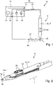
- an electrosurgical device 10 is illustrated in block diagram fashion.
- the electrosurgical device 10 has an electrosurgical instrument 11 and a supply unit 12 .
- the electrosurgical instrument 11 has a connection device 13 which is set up to establish an electrical and fluidic connection and, in the exemplary embodiment shown here, also an optical connection between the electrosurgical instrument 11 and the supply device 12 .
- the connecting device can have at least one connecting element 14, by means of which a preferably detachable connection with the supply device 12 can be established.
- the at least one connecting element 14 can be a connector plug of the connecting device 13, for example.
- connection device 13 also has a plurality of lines 15 in the exemplary embodiment, the Lines 15 contain fluidic lines, at least one electrical line and optionally at least one optical line.
- the lines 15 extend from the at least one connecting element 14 into a casing 17 of the electrosurgical instrument 11.
- the casing 17 is formed by a housing 16 .
- connecting element 14 for example a connecting element 14 for connecting the fluidic lines 15, a connecting element 14 for connecting the at least one electrical line and optionally a connecting element 14 for connecting an optical line 15.
- the supply device 12 is set up to supply the fluids required for the operation of the electrosurgical instrument 11, to provide electrical energy for the operation and to discharge fluids.
- the supply device 12 in the exemplary embodiment has a voltage source 18 by means of which an electrical voltage, in particular a high-frequency alternating voltage, can be provided.
- the supply device 12 also has a rinsing fluid source 19 for supplying the electrosurgical instrument 11 with a rinsing fluid and a suction unit 20. Fluids can be removed from the distal end region of the electrosurgical instrument 11 by means of the suction unit 20.
- the electrosurgical device 10 also has a light analysis unit 21, which in the embodiment is arranged outside of the housing 16 of the electrosurgical instrument 11 . It can be part of the supply device 12, as shown in figure 1 is illustrated. As an alternative to this, the light analysis unit 21 can also be arranged outside of the supply device 12 as a separate unit.
- the electrosurgical instrument 11 has at least one electrode 25 which is electrically connected to the connection device 13 .
- a voltage potential and in particular a high-frequency AC voltage potential can be applied to the electrode 25 via the connection device 13 by means of the voltage source 18 .
- FIG 1 1 illustrates an embodiment of electrosurgical instrument 11 in the form of a monopolar instrument having only one electrode 25 .
- a separate counter-electrode 27 is electrically connected to the supply device 12 and in particular to the voltage source 18 in order to be able to achieve a closed electric circuit via the biological tissue 26 to be treated.
- the counter-electrode 27 can be attached to the patient for this purpose.
- the electrosurgical instrument 11 can also be designed as a bipolar or multipolar instrument with at least two electrodes 25, so that a separate counter-electrode 27 can be dispensed with.
- the circuit can then be closed via the at least two electrodes 25 of the electrosurgical instrument 11 and via the biological tissue 26 to be treated.
- the electrosurgical instrument 11 is equipped with a handle 28 by means of which a surgeon holds or guides the electrosurgical instrument 11 .
- the handle 28 can be formed by a part of the housing 16 or can be attached to the housing 16 .
- the at least one operating element 29 can be used, for example, to apply a desired voltage potential to the electrode 25 and/or to control the supply of a rinsing fluid by means of the rinsing fluid source 19 and/or to control suction by means of the suction unit 20.
- the sheath 17 and, for example, the housing 16 has an end opening 30 at its distal end Figures 1 to 4 the at least one electrode 25 protrudes in a longitudinal direction L beyond the distal end of the housing 16 or the casing 17 and can extend through the end opening 30 .
- the longitudinal direction L is defined in particular by the direction in which the electrode 25 extends, starting from its distal end, and/or the direction in which the longitudinal axis of the covering 17 or the housing 16 extends.
- the longitudinal direction L is oriented at right angles to a plane in which the end opening 30 extends.
- the housing 16 may be comprised of multiple pieces assembled together. As an alternative to this, the housing 16 can also be designed in one piece.
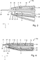
- the distal end section 16a of the housing 16 adjoining the end opening 30 is illustrated enlarged in a schematic cross section.
- the housing 16 delimits a flow space 31 immediately following the end opening 30 present at the distal end.
- the scavenging channel 32 thus opens into the flow chamber 31 at the outlet opening 33 .
- the outlet opening 33 and/or the section of the scavenging channel 32 adjoining it are aligned at an acute angle to the longitudinal direction L, for example.
- the main direction of flow of the flushing fluid flow SF following the outlet opening 33 corresponds, for example, to the longitudinal center axis of the section of the flushing channel 32 that adjoins the outlet opening 33, which is aligned at an angle of, for example, a maximum of 30° or a maximum of 20° or a maximum of 10° relative to the longitudinal direction L can.
- the main flow direction can also be oriented parallel to the longitudinal direction L.
- the electrosurgical instrument 11 also has a suction channel 34 which opens directly into the flow space 31 via an inlet opening 35 .
- fluid can be conducted away from the flow space 31, in particular flushing fluid F.
- smoke gases R that arise during the treatment of biological tissue 26 can be sucked off via the suction channel 34.
- flue gases R can be sucked into the flow space 31 via the end opening 30 and continue into the suction channel 34 via the inlet opening 35 .
- the electrode 25 is arranged between the outlet opening 33 of the flushing channel 32 and the inlet opening 35 of the suction channel 34 when viewed at right angles to the longitudinal direction L.
- the suction channel 34 is fluidically connected to the suction unit 20 and the rinsing channel 32 is fluidly connected to the rinsing fluid source 19 . There is also an electrical connection between the voltage source 18 and the electrode 25.
- the electrosurgical instrument also has a light guide device 40 which has a light entry surface 41 facing the flow space 31 or the at least one electrode 25 .
- the light guide device 40 can be formed, for example, by a light guide, such as a glass fiber.
- the light entry surface 41 can be formed by the end face of the light guide.
- the light guide can be coupled to an optical system, for example a lens, on which the light entry surface 41 is present.
- the light entry surface 41 is aligned in such a way that it can receive light that is emitted at the electrode 25 is emitted when processing the biological tissue 26 by sparking. This light is forwarded via the light guide device 40 to the light analysis unit 21 for evaluation, in particular for spectral analysis. This allows conclusions to be drawn about the type of tissue being processed.
- the light entry surface 41 is sensitive to contamination. Contamination of the light entry surface 41 can be prevented or at least reduced by the flushing fluid F introduced into the flow chamber 31 .
- tissue particles, smoke gas particles, tissue fluid or the like can reach the light entry surface 41 and accumulate there. It has been shown that the protection of the light entry surface 41 from contamination can be improved if the flushing fluid F remains at least essentially within the flow space 31 and does not exit through the end opening 30 or only to a lesser extent.
- the impingement of the rinsing fluid F on the tissue 26 can cause dirt particles to be thrown through the end opening 30 onto the light entry surface 41 .
- the fact that the proportion of the rinsing fluid F impinging on the biological tissue 26 is reduced reduces the risk of such contamination of the light entry surface 41.
- the flow space 31 is formed within the cover 17 or the housing 16 so that rinsing fluid F can be removed via the suction channel 34 before it leaves the cover 17 or the housing 16 . It is advantageous if essentially all of the flushing fluid F is discharged via the suction channel 34 is supplied via the scavenging channel 32 into the flow space 31 . As explained, smoke gases R can also be conveyed away from the treatment site via the suction channel 34 .
- the rinsing fluid F flows around the light entry surface 41 and in particular the adjoining section of the light guide device 40 , in particular before the rinsing fluid F emerges at the outlet opening 33 into the flow space 31 .
- the distal end section of the light guide device 40 is arranged immediately adjacent to the light entry surface 41 directly adjacent to the flushing channel 32 or within the flushing channel 32, as is the case, for example, in FIGS Figures 3 and 4 is illustrated. It is advantageous if the light entry surface 41 is at a greater distance from the end opening 30 in the longitudinal direction L than the exit opening 33.
- outlet opening 33 is at a distance in the longitudinal direction L from the distally arranged end opening 30 which is at least as great as the distance in the longitudinal direction L between the inlet opening 35 of the suction channel 34 and the end opening 30. This arrangement ensures that Aspirating the flushing fluid F out of the flow chamber 31 is simplified or improved.
- the mass or volume flow that is supplied by the rinsing fluid source 19 via the rinsing channel 32 into the flow chamber 31 is at most as large as the mass or volume flow of the flow in the suction channel 34, which is set by means of the suction unit 20 will.
- the Mass or volume flow of the flow in the suction channel 34 is greater than the mass or volume flow in the flushing channel 32.
- the exemplary embodiment of the electrosurgical instrument 11 described so far is set up in particular for use in open surgery.
- a modified embodiment of the electrosurgical instrument is in figure 5 illustrated, which is particularly suitable for laparoscopic interventions or interventions with a flexible endoscope or minimally invasive surgical interventions.
- FIG. 12 shows a schematic cross section of a distal end portion 17a of a sheath 17 of the electrosurgical instrument.
- the casing 17 is formed by a flexible hose 45 or a rigid tube 46 in this embodiment.
- the casing 17 can also be designed as a flexible tube 45 in at least one section and as a rigid tube 46 in at least one other section.
- the casing 17 has a hollow-cylindrical shape, at least in the distal end section 17a.
- An electrode carrier 47 is arranged inside the casing 17 and is electrically connected to at least one electrode 25 and an electrical conductor 48 .
- the electrical conductor 48 extends within the casing 17 and is electrically connected to the connection device 13 .
- the electrode carrier 47 is arranged inside an inner tube 49 or an inner tube 50 .
- a flexible inner hose 49 or a rigid inner tube 50 can be selected to match the casing 17 .
- the scavenging channel 32 which runs, for example, along the longitudinal axis of the casing 17 , extends through the inner tube 49 or the inner tube 50 .
- the light guide device 40 and the light entry surface 41 are arranged within the flushing channel 32 .
- the electrode carrier 47 is arranged adjacent to the scavenging channel 32 and can enclose the scavenging channel 32 coaxially, for example.
- a thermal shielding can be present between the electrode carrier 47 and the scavenging channel 32 , which is a component of a shielding element 51 , for example.
- a first section of the shielding element 51 coaxially encloses the distal end section of the flushing channel 32 and, for example, forms the outlet opening 33. Following this first section, which extends coaxially with the flushing channel 32, the shielding element 51 has a cup-shaped second section, which is arranged within the flow chamber 31 .
- the at least one electrode 25 extends from the electrode carrier 47 through the shielding element 51 into the interior of the cup-shaped second section of the shielding element 51.
- the distal end of the at least one electrode 25 preferably ends within the second section of the shielding element 51.
- the distal end of the shielding element 51 is, for example, at the same height as the distal end of the inner tube 49 or the inner tube 50.
- the distal end of the inner tube 49 or the inner tube 50 and/or the distal end of the shielding element 51 are, for example, in the longitudinal direction L at a distance from the distal end End opening 30 located within the envelope 17.
- the suction channel 34 is formed, for example, by a radial spacing between the inner tube 49 or the inner tube 50 on the one hand and the casing 17 (tube 45 or tube 46).
- a plurality of spacers 52 are preferably arranged in the suction channel 34 in order to define the relative position between the inner tube 49 or the inner tube 50 on the one hand and the covering 17 on the other.
- the inner hose 49 or the inner tube 50 and the casing 17 can be arranged coaxially at least in sections and/or non-coaxially at least in sections.
- the flow through the suction channel 34 can flow past the spacers 52 .
- the dimension and/or shape and/or position and/or surface finish of one or more or all spacers 52 can be selected in order to influence a flow property of the flow through the suction channel 34 .
- the volume flow through the suction channel 34 can be set or throttled in a targeted manner.
- the inlet opening 35 of the suction channel 34 and the outlet opening 33 of the flushing channel 32 are arranged within the casing 17 and in the longitudinal direction L at a distance from the end opening 30 of the casing 17 .
- the distance between the outlet opening 33 and the end opening 30 is greater than the distance between the inlet opening 35 and the end opening 30.
- the exemplary embodiments of the electrosurgical instrument 11 or the electrosurgical device 10 described above work during the treatment of biological tissue 26 as follows:
- the electrosurgical instrument 11 is connected to the supply device 12 by means of the connection device 13 . If necessary, the counter-electrode 27 is attached to the patient and also connected to the supply device 12 . As explained, a separate counter-electrode 27 is not required in the case of bipolar electrosurgical instruments 11 .
- the operator uses the at least one operating element 29 to control the operation of the electrosurgical instrument 11 and, for example, the application of an AC voltage potential to the at least one electrode 25 in order to treat the biological tissue 26, for example to cut or seal it.
- the light analysis unit 21 is set up to analyze the received light, in particular by means of a spectral analysis, in order to determine the type of tissue 26 that is currently being treated using the electrosurgical instrument 11 .
- rinsing fluid F is introduced into the rinsing channel 32 by means of the rinsing fluid source 19 and flows there via the outlet opening 33 into the flow space 31 .
- At most a smaller portion of the flushing fluid F can leave the flow space 31 through the end opening 30 .
- no flushing fluid F exits the end opening 30 .
- the flushing fluid F is sucked out of the flow chamber 31 by means of the suction unit 20, which adjusts a correspondingly large volume flow or negative pressure and consequently a correspondingly large suction capacity in order to achieve the desired effect.
- the smoke gases R produced during the treatment of the tissue 26 are also sucked into the suction channel 34 through the end opening 30 and the inlet opening 35 and discharged.
- At least one sensor 55 can be arranged in the suction channel 34 .
- the at least one sensor 55 is preferably electrically connected to the connection device 13 so that an electrical sensor signal can be transmitted to the supply device 12 via the connection device 13 .
- the at least one sensor 55 is set up to detect a parameter of the flow within the suction channel 34, such as a pressure, a flow rate, a volume flow, etc.
- a parameter of the flow within the suction channel 34 such as a pressure, a flow rate, a volume flow, etc.
- Several different sensors 55 can be present for measuring different parameters. In this configuration, there is the possibility of controlling the suction unit 20 based on setpoint values for the at least one flow parameter.
- FIG 6 a distal end portion 16a of another alternate embodiment of the electrosurgical instrument 11 is illustrated.
- the electrosurgical instrument 11 is constructed similarly to the exemplary embodiment according to FIG Figures 3 and 4 .
- the following are the differences from the embodiment the Figures 3 and 4 explained and otherwise reference is made to the above description.
- the housing 16 has a distal end section 16a, in which the end opening 30 is directly adjoined by a region 57 whose cross-section can be changed by means of an adjusting device 56.
- the area 57 of the end section 16a of the housing 16 can consist, for example, of a flexible or elastic material which can be elastically deformed under the action of the adjustment device 56 .
- the setting device 56 can be operated manually, for example with a finger 58.
- the adjustment device 56 includes an adjustment ring 59 which is mounted so that it can be displaced in the longitudinal direction L and surrounds the area 57 .
- the area 57 has a changing outer diameter and/or a changing outer circumference.
- the position of the adjustment ring 59 relative to the area 57 specifies its outer circumference at this point. This in turn defines the internal cross section of the region 57 and consequently the flow cross section and the cross section of the end opening 30 .
- the area 57 of the distal end section 16a viewed radially to the longitudinal direction L, becomes larger or smaller depending on the relative position between the adjustment ring 59 and the area 57 in the longitudinal direction L.
- the adjustment ring 59 is in the embodiment arranged on a carrier 60 arranged to be displaceable on the housing 16 in the longitudinal direction L.
- the carrier 60 can be arranged to be displaceable in the longitudinal direction L, for example, on a cylindrical bearing part 61 .
- the bearing part 61 can be formed at least partially by the housing 16 and/or by additional components connected to the housing 16 . At least part of the carrier 60 can partially or completely enclose the bearing part 61 in the circumferential direction around the longitudinal direction L.
- a stop 62 can be present on the bearing part 61 towards the distal end in order to limit the movement of the carrier 60 in the longitudinal direction and thus the movement of the adjustment ring 59 in the longitudinal direction L.
- another stop can also be present, which limits the movement in the proximal direction, if this is necessary.
- the movement in the proximal direction is stopped at the in figure 6 illustrated embodiment is limited in that the area 57 merges at one point into a non-deformable, in particular non-elastic part of the housing 16, so that the adjustment ring 59 can only be moved at most up to the non-deformable part of the housing 16.
- the invention relates to an electrosurgical instrument 11 which can be connected to a supply device 12 for operation.
- the electrosurgical instrument 11 has an end opening 30 at the distal end and carries at least one electrode 25 in the area of the end opening 30 which an alternating voltage potential can be applied.
- a cover 17 of the electrosurgical instrument 11 delimits a flow space 31 within the cover 17.
- a flushing channel 32 opens into the flow space 31 via an outlet opening 33, and a suction channel 34 opens out via an inlet opening 35 into the flow space 31.
- a flushing fluid F can be introduced into the flow space 31 via the flushing channel 32 and sucked off via the suction channel 34.
Landscapes
- Health & Medical Sciences (AREA)
- Life Sciences & Earth Sciences (AREA)
- Surgery (AREA)
- Engineering & Computer Science (AREA)
- Heart & Thoracic Surgery (AREA)
- Physics & Mathematics (AREA)
- Public Health (AREA)
- Veterinary Medicine (AREA)
- Biomedical Technology (AREA)
- Animal Behavior & Ethology (AREA)
- General Health & Medical Sciences (AREA)
- Medical Informatics (AREA)
- Molecular Biology (AREA)
- Nuclear Medicine, Radiotherapy & Molecular Imaging (AREA)
- Biophysics (AREA)
- Pathology (AREA)
- Plasma & Fusion (AREA)
- Otolaryngology (AREA)
- Radiology & Medical Imaging (AREA)
- Optics & Photonics (AREA)
- Spectroscopy & Molecular Physics (AREA)
- Pulmonology (AREA)
- Vascular Medicine (AREA)
- Anesthesiology (AREA)
- Hematology (AREA)
- Neurosurgery (AREA)
- Neurology (AREA)
- Cardiology (AREA)
- Surgical Instruments (AREA)
Abstract
Description
- Die Erfindung betrifft ein elektrochirurgisches Instrument, die über ein Versorgungsgerät gespeist werden kann, insbesondere mit elektrischer Energie und einem Spülfluid. Das Versorgungsgerät kann außerdem weitere Einrichtungen oder Einheiten aufweisen, die elektrisch und/oder fluidisch und/oder optisch mit dem Instrument verbunden werden können. Die Erfindung betrifft auch eine elektrochirurgische Vorrichtung aufweisend ein elektrochirurgisches Instrument, das an ein Versorgungsgerät angeschlossen ist sowie ein Verfahren zum Betreiben einer solchen elektrochirurgischen Vorrichtung.
-
EP 2 815 713 A1 beschreibt ein elektrochirurgisches Instrument aufweisend eine Lichtleiteinrichtung sowie wenigstens eine Elektrode. Mittels der Elektrode kann biologisches Gewebe behandelt werden, beispielsweise zur Dissektion oder Koagulation des Gewebes. Das dabei durch Funkenbildung zwischen der Elektrode und dem Gewebe entstehende Licht kann über eine Lichteintrittsfenster aufgenommen und über die Lichtleiteinrichtung an eine Lichtanalyseeinheit weitergeleitet werden. Basierend auf einer Lichtanalyse kann dann die Art des Gewebes erkannt werden, das mittels der wenigstens einen Elektrode behandelt wird. Zur Aufnahme des Lichts wird an dem Instrument ein Fluidkörper gebildet. Dieser Fluidkörper kann durch einen Fluidkanal und Fluidaustrittsöffnungen am distalen Ende während des Betriebs des Instruments erneuert werden. - Ein ähnliches elektrochirurgisches Instrument ist in
EP 3 517 028 A1 beschrieben. - Es kann als Aufgabe der vorliegenden Erfindung angesehen werden, ein elektrochirurgisches Instrument zu schaffen, das eine verbesserte Schutzwirkung gegen eine Verschmutzung einer Lichteintrittsfläche einer Lichtleiteinrichtung aufweist.
- Diese Aufgabe wird durch ein elektrochirurgisches Instrument mit den Merkmalen des Patentanspruches 1, eine elektrochirurgische Vorrichtung mit den Merkmalen des Patentanspruches 10 sowie ein Verfahren mit den Merkmalen des Patentanspruches 14 gelöst.
- Das erfindungsgemäße elektrochirurgische Instrument kann zur offenchirurgischen oder laparoskopischen Anwendung eingerichtet sein. Zur Verbindung mit einem Versorgungsgerät hat das elektrochirurgische Instrument eine Anschlusseinrichtung. Über die Anschlusseinrichtung kann eine elektrische, optische und fluidische Verbindung zwischen dem elektrochirurgischen Instrument und dem Versorgungsgerät hergestellt werden. Die Anschlusseinrichtung kann beispielsweise einen oder mehrere Stecker oder andere geeignete Verbindungselemente aufweisen, mit denen insbesondere eine lösbare Verbindung zwischen dem Versorgungsgerät und dem elektrochirurgischen Instrument herstellbar ist. Die elektrische Verbindung, die optische Verbindung und die fluidische Verbindung können dabei über einen oder mehrere gemeinsame oder separate Stecker oder andere geeignete Verbindungselemente hergestellt werden.
- Das elektrochirurgische Instrument weist außerdem eine Umhüllung mit einer Endöffnung am distalen Ende der Umhüllung auf. Die Umhüllung kann bei einem Ausführungsbeispiel durch ein Gehäuse oder einen Teil des Gehäuses gebildet sein, beispielsweise bei der Ausgestaltung für den offenchirurgischen Einsatz. Ein Teil des Gehäuses kann als Handgriff dienen oder einen Handgriff aufweisen. An dem Gehäuse können außerdem ein oder mehrere Bedienelemente zur manuellen Betätigung vorhanden sein.
- Es ist auch möglich, die Umhüllung durch einen flexiblen Schlauch, ein starres Rohr oder eine Kombination aus flexiblen Schlauch- und starren Rohrabschnitten zu bilden, beispielsweise bei einem elektrochirurgischen Instrument für den laparoskopischen Einsatz in Kombination mit einem Endoskop oder den Einsatz mit einem flexiblen Endoskop. Die Umhüllung kann somit abhängig von der Ausgestaltung zumindest abschnittsweise starr oder flexibel sein. Die Umhüllung kann beispielsweise aus Kunststoff und/oder einer Metalllegierung bestehen.
- Die Anschlusseinrichtung kann an einem proximalen Ende der Umhüllung angeordnet sein. Die Anschlusseinrichtung kann eine oder mehrere Leitungen und/oder einen oder mehrere Stecker oder ähnliche Verbindungselemente aufweisen.
- Das Instrument hat an seinem distalen Ende wenigstens eine Elektrode. Die wenigstens eine Elektrode ist elektrisch mit der Anschlusseinrichtung verbunden und kann daher über die Anschlusseinrichtung mit dem Versorgungsgerät verbunden werden. Die wenigstens eine Elektrode ist abhängig von der Ausführungsform benachbart zur Endöffnung der Umhüllung angeordnet oder ragt in einer Längsrichtung über die Endöffnung hinaus, wobei sich die wenigstens eine Elektrode durch die Endöffnung hindurch erstrecken kann. Die Längsrichtung ist die Richtung, in der sich das Instrument zumindest im Anschluss an die Endöffnung der Umhüllung erstreckt und/oder die Richtung, in die sich die wenigstens eine Elektrode im Anschluss an ihr distales Ende erstreckt. Bei einem Ausführungsbeispiel kann eine Ebene, in der sich die Endöffnung erstreckt, rechtwinkelig zur Längsrichtung ausgerichtet sein.
- Das elektrochirurgische Instrument kann als monopolares oder als bipolares oder als multipolares Instrument ausgebildet sein. Bei der Ausgestaltung als monopolares Instrument ist eine einzige Elektrode am Instrument ausreichend. Eine weitere Elektrode, die als Gegenelektrode bezeichnet werden kann, kann separat von dem elektrochirurgischen Instrument ausgebildet und mit dem Versorgungsgerät verbunden werden. Wenn das elektrochirurgische Instrument als bipolares Instrument ausgestaltet ist, sind wenigstens zwei Elektroden vorhanden, zwischen denen beim Betrieb eine Spannung anliegen kann.
- Das elektrochirurgische Instrument hat außerdem eine optisch mit der Anschlusseinrichtung verbundene Lichtleiteinrichtung. An ihrem distalen Ende hat die Lichtleiteinrichtung eine Lichteintrittsfläche, die innerhalb der Umhüllung angeordnet ist und die im Wesentlichen zur Endöffnung und/oder zu der wenigstens einen Elektrode hin ausgerichtet ist. Die Lichteintrittsfläche ist derart angeordnet und orientiert, dass bei einer Funkenbildung an der wenigstens einen Elektrode entstehendes Licht durch die Lichteintrittsfläche einfallen und über die Lichtleiteinrichtung optisch zur Anschlusseinrichtung weitergeleitet werden kann. Das aufgenommene Licht kann über die Anschlusseinrichtung an das Versorgungsgerät weitergeleitet werden und dort beispielsweise in einer Lichtanalyseeinheit analysiert werden. Wenn die Lichtanalyseeinheit bei einem Ausführungsbeispiel Bestandteil des elektrochirurgischen Instruments ist, ist die Lichtleiteinrichtung mit der Lichtanalyseeinheit direkt verbunden und eine optische Verbindung mit der Anschlusseinrichtung kann entfallen.
- Das elektrochirurgische Instrument hat außerdem einen fluidisch mit der Anschlusseinrichtung verbundenen Spülkanal, der vorzugsweise innerhalb der Umhüllung verläuft. Der Spülkanal hat an seinem distalen Ende eine Austrittsöffnung, die in einen von der Umhüllung begrenzten Strömungsraum mündet. Die Austrittsöffnung ist in Längsrichtung mit Abstand zur Endöffnung angeordnet. In Längsrichtung gegenüberliegend mündet die Endöffnung der Umhüllung in den Strömungsraum. Der Strömungsraum ist somit in Längsrichtung betrachtet zwischen der Austrittsöffnung und der Endöffnung angeordnet. Aus der Austrittsöffnung strömendes Spülfluid bildet im Strömungsraum eine Spülfluidströmung. Vorzugsweise ist die Spülfluidströmung zumindest im Wesentlichen von der Austrittsöffnung weg zur Endöffnung hin gerichtet. Mittels der Spülfluidströmung im Strömungsraum kann das Eindringen von Verunreinigungen, die die Lichteintrittsfläche verunreinigen könnten, vermieden oder zumindest reduziert werden.
- Das elektrochirurgische Instrument weist außerdem einen fluidisch mit der Anschlusseinrichtung verbundenen Absaugkanal auf, der vorzugsweise in der Umhüllung angeordnet ist. Der Absaugkanal hat eine in den Strömungsraum mündende Eintrittsöffnung. Über die Eintrittsöffnung und den Absaugkanal kann zumindest ein Teil des Spülfluids aus dem Strömungsraum abgeführt werden. Vorzugsweise ist der Absaugkanal derart dimensioniert, dass im Wesentlichen das gesamte Spülfluid aus dem Strömungsraum abgeführt werden kann, bevor das Spülfluid über die Endöffnung aus dem Strömungsraum austritt.
- Somit kann beispielsweise die Menge des Spülfluids eingestellt werden, das die Endöffnung verlässt und auf das zu behandelnde biologische Gewebe auftrifft. Der überwiegende Anteil des in den Strömungsraum eintretenden Spülfluids oder das gesamte in den Strömungsraum eintretende Spülfluid kann über den Absaugkanal abgeführt werden, bevor das Spülfluid aus der Endöffnung austritt. Es hat sich gezeigt, dass dadurch die Verschmutzung der Optik und insbesondere der Lichteintrittsfläche der Lichtleiteinrichtung erheblich verringert werden kann, was zu einer besseren Analyse des aktuell behandelten biologischen Gewebes führt. Der Volumenstrom des Spülfluids kann gegenüber früheren Instrumenten deutlich erhöht werden und ist vorzugsweise größer als 1 l/min. und kann beispielsweise etwa bis zu 8 l/min. betragen.
- Es ist möglich, mehrere Absaugkanäle mit jeweils einer Eintrittsöffnung bereitzustellen. Zusätzlich oder alternativ ist es auch möglich, mehrere Spülkanäle mit jeweils einer Austrittsöffnung bereitzustellen.
- Bei einer Ausführungsform kann die Austrittsöffnung des Spülkanals bzw. der sich an die Austrittsöffnung anschließende Abschnitt des Spülkanals derart ausgerichtet sein, dass die Hauptströmungsrichtung parallel zur Längsrichtung oder unter einem spitzen Winkel geneigt zur Längsrichtung in den Strömungsraum eintritt. Die Hauptströmungsrichtung kann durch die Mittelachse definiert sein, die rechtwinklig zur Ebene der Austrittsöffnung ausgerichtet ist.
- Die Eintrittsöffnung des Absaugkanals ist in Längsrichtung vorzugsweise mit Abstand zur Endöffnung angeordnet. Es ist vorteilhaft, wenn die Eintrittsöffnung des Absaugkanals in Längsrichtung näher an der Endöffnung angeordnet ist als die Austrittsöffnung des Spülkanals. Alternativ können die Eintrittsöffnung und die Austrittsöffnung in Längsrichtung denselben Abstand von der Endöffnung aufweisen. Bei dieser Ausgestaltung ist es möglich, dass die Eintrittsöffnung und die Austrittsöffnung in einer gemeinsamen Ebene angeordnet sind.
- Wie bereits erläutert, kann es vorteilhaft sein, wenn das elektrochirurgische Instrument derart dimensioniert ist oder betrieben wird, dass kein Spülfluid der Spülfluidströmung durch die Endöffnung aus dem Strömungsraum austritt. Dies kann beispielsweise dadurch erreicht werden, dass der Volumenstrom des Spülfluids durch den Spülkanal maximal so groß ist wie der Volumenstrom der Strömung durch den Absaugkanal. Zusätzlich kann auch die Geometrie des Strömungsraums und/oder die Anordnung und Ausrichtung der Austrittsöffnung des Spülkanals und/oder die Anordnung und Ausrichtung der Eintrittsöffnung des Absaugkanals die Strömungsrichtung der Spülfluidströmung im Strömungsraum derart gewählt werden, dass das Eintreten des Spülfluids in den Absaugkanal erleichtert wird. Beispielsweise kann sich der Strömungsraum zur Endöffnung hin verjüngen. Zusätzlich oder alternativ können die Austrittsöffnung und die Eintrittsöffnung derart angeordnet und orientiert sein, dass die Spülfluidströmung eine Strömungsrichtungskomponente von der Austrittsöffnung zur Eintrittsöffnung hin aufweist.
- Es ist außerdem vorteilhaft, wenn die Lichteintrittsfläche der Lichtleiteinrichtung in Längsrichtung einen größeren Abstand von der Endöffnung aufweist als die Austrittsöffnung des Spülkanals. Dadurch lässt sich der Schutz der Lichteintrittsfläche weiter verbessern.
- Bei einem Ausführungsbeispiel kann die Lichteintrittsfläche bzw. der sich an die Lichteintrittsfläche anschließende distale Endabschnitt der Lichtleiteinrichtung im Spülkanal angeordnet sein und/oder unmittelbar benachbart zur Austrittsöffnung angeordnet sein, so dass die Lichteintrittsfläche bzw. der sich anschließende distale Endabschnitt der Lichtleiteinrichtung von Spülfluid umströmt wird, insbesondere bevor das Spülfluid die Austrittsöffnung verlässt. Auch durch diese Maßnahme ist eine verbesserte Schutzwirkung gegen Verschmutzung der Lichteintrittsfläche erreicht.
- Es kann vorteilhaft sein, wenn neben dem Absaugkanal wenigstens ein elektrisch mit der Anschlusseinrichtung verbundener Sensor vorhanden ist. Mittels des wenigstens einen Sensors kann ein Parameter der Strömung bzw. des Fluids im Absaugkanal erfasst werden, wie beispielsweise ein Druck, ein Volumenstrom, eine Strömungsgeschwindigkeit oder ein anderer physikalischer Parameter oder eine beliebige Kombination mehrerer der genannten Parameter.
- Eine erfindungsgemäße elektrochirurgische Vorrichtung weist ein elektrochirurgisches Instrument auf, das einem der vorstehend erläuterten Ausführungsbeispiele entspricht. Mittels der Anschlusseinrichtung ist das elektrochirurgische Instrument an ein Versorgungsgerät angeschlossen. Eine Lichtanalyseeinheit ist optisch mit der Lichtleiteinrichtung bzw. der Lichteintrittsfläche verbunden und dazu eingerichtet, eine Analyse des empfangenen Lichts durchzuführen, insbesondere eine Spektralanalyse. Die Lichtanalyseeinheit kann Bestandteil des elektrochirurgischen Instruments oder des Versorgungsgeräts sein oder separat dazu ausgebildet sein. Wenn die Lichtanalyseeinheit nicht Bestandteil des elektrochirurgischen Instruments ist, ist die Lichtanalyseeinheit optisch mit der Anschlusseinrichtung verbunden, so dass über die Anschlusseinrichtung das Licht an die Lichtanalyseeinheit weitergeleitet werden kann.
- Das Versorgungsgerät hat eine Spannungsquelle, die elektrisch mit der wenigstens einen Elektrode des elektrochirurgischen Instruments verbunden ist. Dadurch kann ein elektrisches Spannungspotential, insbesondere ein hochfrequentes Wechselspannungspotential an die wenigstens eine Elektrode angelegt werden.
- Außerdem weist das Versorgungsgerät eine Spülfluidquelle auf, die fluidisch mit dem Spülkanal verbunden ist sowie eine Absaugeinheit die fluidisch mit dem Absaugkanal verbunden ist. Mittels der Spülfluidquelle kann dem Spülfluidkanal Spülfluid zugeführt und dadurch die Spülfluidströmung erzeugt werden. Mittels der Absaugeinheit kann eine Absaugströmung durch den Absaugkanal erzeugt werden, um zumindest einen Teil des Spülfluids oder das gesamte Spülfluid aus dem Strömungsraum abzuführen.
- Dabei kann der Volumenstrom des Spülfluids und der Volumenstrom der Absaugströmung angepasst an die Anwendung eingestellt werden, wobei der Volumenstrom der Absaugströmung mindestens so groß ist wie der Volumenstrom des Spülfluids und vorzugsweise größer. Bevorzugt wird bzw. werden der Volumenstrom der Absaugströmung und/oder eine Absaugleistung der Absaugeinheit derart eingestellt, dass kein Spülfluid oder lediglich ein geringer Teil des Spülfluids aus der Endöffnung der Umhüllung austritt.
- Mittels der Absaugeinheit kann auch eine Absaugleistung und/oder ein Volumenstrom der Absaugströmung eingestellt werden, so dass Rauchgase oder andere Gase, die bei der Behandlung von Gewebe mittels des elektrochirurgischen Instruments entstehen, über die Endöffnung, die Eintrittsöffnung und den Absaugkanal abgesaugt werden.
- Während des Betriebs der elektrochirurgischen Vorrichtung wird ein Spannungspotential an die wenigstens eine Elektrode angelegt. Spülfluid wird über den Spülkanal in den Strömungsraum geleitet und zumindest ein Teil davon über die Eintrittsöffnung und den Absaugkanal aus dem Strömungsraum abgeführt. Während der Behandlung des Gewebes, beispielsweise der Dissektion oder der Koagulation des Gewebes, entsteht an der wenigstens einen Elektrode ein Funken, der Licht emittiert. Das Lichtspektrum ist charakteristisch für die Art des behandelten Gewebes. Das Licht kann über die Lichteintrittsfläche einfallen und über die Lichtleiteinrichtung an die Lichtanalyseeinheit weitergeleitet werden, so dass eine Auswertung über die Art des behandelten Gewebes in der Lichtanalyseeinheit möglich ist. Das Ergebnis der Analyse kann dem Operateur optisch und/oder akustisch und/oder haptisch angezeigt werden.
- Bei allen Ausführungsformen der Erfindung kann das Spülfluid gasförmig oder flüssig sein. Als Spülfluid kann beispielsweise, Kohlenstoffdioxid oder Luft oder Argon oder eine beliebige Kombination davon verwendet werden. Insbesondere eignet sich Argon zur endoskopischen Verwendung des Instruments und Kohlenstoffdioxid und/oder Luft zur offenchirurgischen Verwendung des Instruments.
- Vorteilhafte Ausgestaltungen der Erfindung ergeben sich aus den abhängigen Patentansprüchen, der Beschreibung und den Zeichnungen. Nachfolgend werden bevorzugte Ausführungsbeispiele der Erfindung anhand der beigefügten Zeichnungen erläutert. Die Zeichnungen umfassen folgende Figuren:
-
Figur 1 ein Blockschaltbild einer elektrochirurgischen Vorrichtung aufweisend ein elektrochirurgisches Instrument sowie ein Versorgungsgerät, -
Figur 2 eine perspektivische Darstellung eines Ausführungsbeispiels eines elektrochirurgischen Instruments, -
Figuren 3 und 4 jeweils einen sich an das distale Ende des elektrochirurgischen Instruments anschließenden Endabschnitts eines Ausführungsbeispiels des elektrochirurgischen Instruments in einer schematischen Querschnittsdarstellung, -
Figur 5 einen sich an das distale Ende des elektrochirurgischen Instruments anschließenden Endabschnitt eines abgewandelten Ausführungsbeispiels und -
Figur 6 einen sich an das distale Ende des elektrochirurgischen Instruments anschließenden Endabschnitts eines weiteren Ausführungsbeispiels des elektrochirurgischen Instruments in einer schematischen Querschnittsdarstellung. - In
Figur 1 ist nach Art eines Blockschaltbilds eine elektrochirurgische Vorrichtung 10 veranschaulicht. Die elektrochirurgische Vorrichtung 10 weist ein elektrochirurgisches Instrument 11 und ein Versorgungsgerät 12 auf. Das elektrochirurgische Instrument 11 hat eine Anschlusseinrichtung 13, die dazu eingerichtet ist, eine elektrische und fluidische und beim hier dargestellten Ausführungsbeispiel zusätzlich eine optische Verbindung zwischen dem elektrochirurgischen Instrument 11 und dem Versorgungsgerät 12 herzustellen. Hierzu kann die Anschlusseinrichtung wenigstens ein Verbindungselement 14 aufweisen, mittels dem eine vorzugsweise lösbare Verbindung mit dem Versorgungsgerät 12 herstellbar ist. Das wenigstens eine Verbindungselement 14 kann beispielsweise ein Anschlussstecker der Anschlusseinrichtung 13 sein. - Die Anschlusseinrichtung 13 weist beim Ausführungsbeispiel außerdem mehrere Leitungen 15 auf, wobei die Leitungen 15 fluidische Leitungen, wenigstens eine elektrische Leitung und optional wenigstens eine optische Leitung enthalten. Die Leitungen 15 erstrecken sich von dem wenigstens einen Verbindungselement 14 in eine Umhüllung 17 des elektrochirurgischen Instruments 11. Beim Ausführungsbeispiel gemäß der
Figuren 1-4 ist die Umhüllung 17 von einem Gehäuse 16 gebildet. - In Abwandlung zum dargestellten Ausführungsbeispiel könnten auch mehrere separate Verbindungselemente 14 vorhanden sein, beispielsweise ein Verbindungselement 14 zum Anschluss der fluidischen Leitungen 15, ein Verbindungselement 14 zum Anschluss der wenigstens einen elektrischen Leitung und optional ein Verbindungselement 14 zum Anschluss einer optischen Leitung 15.
- Das Versorgungsgerät 12 ist dazu eingerichtet, die für den Betrieb des elektrochirurgischen Instruments 11 erforderliche Fluide zuzuführen, elektrische Energie für den Betrieb bereitzustellen sowie Fluide abzuführen. Hierzu weist das Versorgungsgerät 12 beim Ausführungsbeispiel eine Spannungsquelle 18 auf, mittels der eine elektrische Spannung, insbesondere eine Hochfrequenz-Wechselspannung bereitgestellt werden kann. Das Versorgungsgerät 12 hat außerdem eine Spülfluidquelle 19 zur Versorgung des elektrochirurgischen Instruments 11 mit einem Spülfluid sowie eine Absaugeinheit 20. Mittels der Absaugeinheit 20 können Fluide aus dem distalen Endbereich des elektrochirurgischen Instruments 11 abgeführt werden.
- Die elektrochirurgische Vorrichtung 10 weist außerdem eine Lichtanalyseeinheit 21 auf, die beim Ausführungsbeispiel außerhalb des Gehäuses 16 des elektrochirurgischen Instruments 11 angeordnet ist. Sie kann Bestandteil des Versorgungsgeräts 12 sein, wie es in
Figur 1 veranschaulicht ist. Alternativ dazu kann die Lichtanalyseeinheit 21 auch außerhalb des Versorgungsgeräts 12 als separate Einheit angeordnet sein. - Das elektrochirurgische Instrument 11 hat wenigstens eine Elektrode 25, die elektrisch mit der Anschlusseinrichtung 13 verbunden ist. Über die Anschlusseinrichtung 13 kann mittels der Spannungsquelle 18 ein Spannungspotential und insbesondere ein Hochfrequenz-Wechselspannungspotential an die Elektrode 25 angelegt werden. In
Figur 1 ist eine Ausführungsform des elektrochirurgischen Instruments 11 in Form eines monopolaren Instruments veranschaulicht, das lediglich eine Elektrode 25 aufweist. Um bei der Behandlung von biologischem Gewebe 26 mittels des elektrochirurgischen Instruments 11 einen Stromkreis zu schließen, ist eine separate Gegenelektrode 27 elektrisch an das Versorgungsgerät 12 und insbesondere die Spannungsquelle 18 angeschlossen, um einen geschlossenen Stromkreis über das zu behandelnde biologische Gewebe 26 erreichen zu können. Die Gegenelektrode 27 kann hierfür am Patienten angebracht werden. - In Abwandlung zu dem in
Figur 1 dargestellten Ausführungsbeispiel kann das elektrochirurgische Instrument 11 auch als bipolares oder multipolares Instrument mit wenigstens zwei Elektroden 25 ausgebildet sein, so dass auf eine separate Gegenelektrode 27 verzichtet werden kann. Der Stromkreis kann dann über die wenigstens zwei Elektroden 25 des elektrochirurgischen Instruments 11 und über das zu behandelnde biologische Gewebe 26 geschlossen werden. - Bei dem in den
Figuren 1-4 veranschaulichten Ausführungsbeispiel ist das elektrochirurgische Instrument 11 mit einem Handgriff 28 ausgestattet, mittels dem ein Operateur das elektrochirurgische Instrument 11 hält bzw. führt. Der Handgriff 28 kann, wie beim Ausführungsbeispiel, durch einen Teil des Gehäuses 16 gebildet sein oder am Gehäuse 16 angebracht sein. In der Nähe des Handgriffs 28 kann an dem Gehäuse 16 außerdem wenigstens ein Bedienelement 29 vorhanden sein, beispielsweise um das Versorgungsgerät 12 anzusteuern. Über das wenigstens eine Bedienelement 29 kann beispielsweise ein gewünschtes Spannungspotential an die Elektrode 25 angelegt werden und/oder das Zuführen eines Spülfluids mittels der Spülfluidquelle 19 gesteuert werden und/oder das Absaugen mittels der Absaugeinheit 20 gesteuert werden. - Die Umhüllung 17 und beispielsgemäß das Gehäuse 16 hat an ihrem distalen Ende eine Endöffnung 30. Bei dem Ausführungsbeispiel gemäß der
Figuren 1 bis 4 ragt die wenigstens eine Elektrode 25 in einer Längsrichtung L über das distale Ende des Gehäuses 16 bzw. der Umhüllung 17 hinaus und kann sich durch die Endöffnung 30 hindurch erstrecken. Die Längsrichtung L ist insbesondere durch die Richtung definiert, in der sich die Elektrode 25 ausgehend von ihrem distalen Ende erstreckt und/oder die Richtung, in der sich die Längsachse der Umhüllung 17 bzw. des Gehäuses 16 erstreckt. Die Längsrichtung L ist beim Ausführungsbeispiel rechtwinklig zu einer Ebene orientiert, in der sich die Endöffnung 30 erstreckt. - Wie es in
Figur 2 veranschaulicht ist, kann das Gehäuse 16 aus mehreren zusammengefügten Teilen bestehen. Alternativ hierzu kann das Gehäuse 16 auch einteilig ausgebildet sein. - In den
Figuren 3 und 4 ist der sich an die Endöffnung 30 anschließende distale Endabschnitt 16a des Gehäuses 16 vergrößert in einem schematischen Querschnitt veranschaulicht. Das Gehäuse 16 begrenzt unmittelbar im Anschluss an die am distalen Ende vorhandene Endöffnung 30 einen Strömungsraum 31. Ein Spülkanal 32, der vorzugsweise innerhalb des Gehäuses 16 bzw. der Umhüllung 17 verläuft, hat eine Austrittsöffnung 33, die unmittelbar an den Strömungsraum 31 angrenzt. An der Austrittsöffnung 33 mündet der Spülkanal 32 somit in den Strömungsraum 31. Das an der Austrittsöffnung 33 austretende Spülfluid F erzeugt im Strömungsraum 31 eine Spülfluidströmung SF. - Die Austrittsöffnung 33 und/oder der sich daran anschließende Abschnitt des Spülkanals 32 sind beispielsgemäß unter einem spitzen Winkel zur Längsrichtung L ausgerichtet. Die Hauptströmungsrichtung der Spülfluidströmung SF im Anschluss an die Austrittsöffnung 33 entspricht beispielsgemäß der Längsmittelachse des sich an die Austrittsöffnung 33 anschließenden Abschnitts des Spülkanals 32, die unter einem Winkel von beispielsweise maximal 30° oder maximal 20° oder maximal 10° relativ zur Längsrichtung L ausgerichtet sein kann. Bei anderen Ausführungsbeispielen kann die Hauptströmungsrichtung auch parallel zur Längsrichtung L orientiert sein.
- Das elektrochirurgische Instrument 11 hat außerdem einen Absaugkanal 34, der über eine Eintrittsöffnung 35 unmittelbar in den Strömungsraum 31 mündet. Über den Absaugkanal 34 kann Fluid aus dem Strömungsraum 31 weggeleitet werden, insbesondere Spülfluid F. Außerdem können über den Absaugkanal 34 Rauchgase R abgesaugt werden, die während der Behandlung von biologischem Gewebe 26 entstehen. Solche Rauchgase R können über die Endöffnung 30 in den Strömungsraum 31 eingesaugt und weiter über die Eintrittsöffnung 35 in den Absaugkanal 34 gelangen.
- Beim Ausführungsbeispiel ist die Elektrode 25 rechtwinklig zur Längsrichtung L betrachtet zwischen der Austrittsöffnung 33 des Spülkanals 32 und der Eintrittsöffnung 35 des Absaugkanals 34 angeordnet.
- In betriebsbereitem Zustand des elektrochirurgischen Instruments 11 ist der Absaugkanal 34 fluidisch mit der Absaugeinheit 20 verbunden und der Spülkanal 32 ist fluidisch mit der Spülfluidquelle 19 verbunden. Außerdem besteht eine elektrische Verbindung zwischen der Spannungsquelle 18 und der Elektrode 25.
- Das elektrochirurgische Instrument verfügt außerdem über eine Lichtleiteinrichtung 40, die eine dem Strömungsraum 31 bzw. der wenigstens einen Elektrode 25 zugewandte Lichteintrittsfläche 41 aufweist. Die Lichtleiteinrichtung 40 kann beispielsweise durch einen Lichtleiter, wie etwa eine Glasfaser, gebildet sein. Die Lichteintrittsfläche 41 kann durch die Stirnfläche des Lichtleiters gebildet sein. Alternativ dazu kann der Lichtleiter mit einer Optik gekoppelt sein, beispielsweise einer Linse, an der die Lichteintrittsfläche 41 vorhanden ist.
- Die Lichteintrittsfläche 41 ist derart ausgerichtet, dass sie Licht empfangen kann, das an der Elektrode 25 beim Bearbeiten des biologischen Gewebes 26 durch Funkenbildung emittiert wird. Dieses Licht wird über die Lichtleiteinrichtung 40 an die Lichtanalyseeinheit 21 zur Auswertung weitergeleitet, insbesondere zur Spektralanalyse. Dadurch kann auf die Art des bearbeiteten Gewebes geschlossen werden.
- Die Lichteintrittsfläche 41 ist empfindlich gegen Verschmutzung. Über das in den Strömungsraum 31 eingeleitete Spülfluid F kann eine Verschmutzung der Lichteintrittsfläche 41 verhindert oder zumindest gemindert werden. Beispielsweise können Gewebepartikel, Rauchgaspartikel, Gewebeflüssigkeit oder dergleichen auf die Lichteintrittsfläche 41 gelangen und sich dort ansammeln. Es hat sich gezeigt, dass der Schutz der Lichteintrittsfläche 41 vor Verschmutzung verbessert werden kann, wenn das Spülfluid F zumindest im Wesentlichen innerhalb des Strömungsraums 31 verbleibt und nicht oder lediglich zu einem geringeren Teil durch die Endöffnung 30 austritt. Durch das Auftreffen des Spülfluids F auf das Gewebe 26 können Schmutzpartikel durch die Endöffnung 30 auf die Lichteintrittsfläche 41 geschleudert werden. Dadurch, dass der Anteil des auf das biologische Gewebe 26 auftreffenden Spülfluids F verringert wird, reduziert die Gefahr einer derartigen Verschmutzung der Lichteintrittsfläche 41.
- Deswegen ist bei der erfindungsgemäßen Ausgestaltung des elektrochirurgischen Instruments 11 innerhalb der Umhüllung 17 bzw. des Gehäuses 16 der Strömungsraum 31 gebildet, so dass Spülfluid F über den Absaugkanal 34 abgeführt werden kann, bevor es die Umhüllung 17 bzw. das Gehäuse 16 verlässt. Es ist vorteilhaft, wenn im Wesentlichen das gesamte Spülfluid F über den Absaugkanal 34 abgeführt wird, das über den Spülkanal 32 in den Strömungsraum 31 zugeführt wird. Wie erläutert, können zusätzlich auch Rauchgase R über den Absaugkanal 34 von der Behandlungsstelle weg gefördert werden.
- Zum Schutz der Lichteintrittsfläche 41 ist die Lichteintrittsfläche 41 und insbesondere der sich daran anschließende Abschnitt der Lichtleiteinrichtung 40 von dem Spülfluid F umströmt, insbesondere bevor das Spülfluid F an der Austrittsöffnung 33 in den Strömungsraum 31 austritt. Hierzu ist der distale Endabschnitt der Lichtleiteinrichtung 40 im Anschluss an die Lichteintrittsfläche 41 unmittelbar benachbart zum Spülkanal 32 oder innerhalb des Spülkanals 32 angeordnet, wie es beispielsweise in den
Figuren 3 und 4 veranschaulicht ist. Es ist dabei vorteilhaft, wenn die Lichteintrittsfläche 41 in Längsrichtung L einen größeren Abstand zur Endöffnung 30 aufweist als die Austrittsöffnung 33. - Es ist auch bevorzugt, wenn die Austrittsöffnung 33 in Längsrichtung L einen Abstand zur distal angeordneten Endöffnung 30 aufweist, der mindestens so groß ist, wie der Abstand in Längsrichtung L zwischen der Eintrittsöffnung 35 des Absaugkanals 34 und der Endöffnung 30. Durch diese Anordnung wird das Absaugen des Spülfluids F aus dem Strömungsraum 31 vereinfacht bzw. verbessert.
- Beim Betrieb des elektrochirurgischen Instruments 11 ist der Massen- oder Volumenstrom, der mittels der Spülfluidquelle 19 über den Spülkanal 32 in den Strömungsraum 31 zugeführt wird, maximal so groß wie der Massen- oder Volumenstrom der Strömung im Absaugkanal 34, der mittels der Absaugeinheit 20 eingestellt wird. Vorzugsweise ist der Massen- oder Volumenstrom der Strömung im Absaugkanal 34 größer als der Massen- oder Volumenstrom im Spülkanal 32.
- Das bisher beschriebene Ausführungsbeispiel des elektrochirurgischen Instruments 11 ist insbesondere für eine offenchirurgische Anwendung eingerichtet. Ein abgewandeltes Ausführungsbeispiel des elektrochirurgischen Instruments ist in
Figur 5 veranschaulicht, das sich insbesondere auch für laparoskopische Eingriffe oder Eingriffe mit einem flexiblen Endoskop bzw. minimalinvasive chirurgische Eingriffe eignet. -
Figur 5 zeigt einen schematischen Querschnitt eines distalen Endabschnitts 17a einer Umhüllung 17 des elektrochirurgischen Instruments. Die Umhüllung 17 ist bei diesem Ausführungsbeispiel durch einen flexiblen Schlauch 45 oder ein starres Rohr 46 gebildet. Die Umhüllung 17 kann auch in wenigstens einem Abschnitt als flexibler Schlauch 45 und in wenigstens einem anderen Abschnitt als starres Rohr 46 ausgeführt sein. Die Umhüllung 17 hat beim Ausführungsbeispiel zumindest im distalen Endabschnitt 17a eine hohlzylindrische Gestalt. - Innerhalb der Umhüllung 17 ist ein Elektrodenträger 47 angeordnet, der elektrisch mit wenigstens einer Elektrode 25 und einem elektrischen Leiter 48 verbunden ist. Der elektrische Leiter 48 erstreckt sich innerhalb der Umhüllung 17 und ist mit der Anschlusseinrichtung 13 elektrisch verbunden. Der Elektrodenträger 47 ist beim Ausführungsbeispiel innerhalb eines Innenschlauchs 49 oder eines Innenrohrs 50 angeordnet. Angepasst an die Umhüllung 17 kann ein flexibler Innenschlauch 49 oder ein starres Innenrohr 50 gewählt werden.
- Durch den Innenschlauch 49 oder das Innenrohr 50 erstreckt sich der Spülkanal 32, der beispielsweise entlang der Längsachse der Umhüllung 17 verläuft. Die Lichtleiteinrichtung 40 und die Lichteintrittsfläche 41 sind bei diesem Ausführungsbeispiel innerhalb des Spülkanals 32 angeordnet. Im Bereich des distalen Endes des Spülkanals 32 ist benachbart zum Spülkanal 32 der Elektrodenträger 47 angeordnet, der den Spülkanal 32 beispielsweise koaxial umschließen kann. Zwischen dem Elektrodenträger 47 und dem Spülkanal 32 kann eine thermische Abschirmung vorhanden sein, die beispielsweise Bestandteil eines Abschirmelements 51 ist. Ein erster Abschnitt des Abschirmelements 51 umschließt den distalen Endabschnitt des Spülkanals 32 koaxial und bildet beispielsgemäß die Austrittsöffnung 33. Im Anschluss an diesen sich koaxial zum Spülkanal 32 erstreckenden ersten Abschnitt weist das Abschirmelement 51 einen becherförmigen zweiten Abschnitt auf, der innerhalb des Strömungsraums 31 angeordnet ist.
- Die wenigstens eine Elektrode 25 erstreckt sich ausgehend vom Elektrodenträger 47 durch das Abschirmelement 51 in den Innenbereich des becherförmigen zweiten Abschnitts des Abschirmelements 51. Die wenigstens eine Elektrode 25 endet mit ihrem distalen Ende vorzugsweise innerhalb des zweiten Abschnitts des Abschirmelements 51. Das distale Ende des Abschirmelements 51 befindet sich beispielsgemäß auf derselben Höhe wie das distale Ende des Innenschlauchs 49 bzw. des Innenrohrs 50. Das distale Ende des Innenschlauchs 49 bzw. des Innenrohrs 50 und/oder das distale Ende des Abschirmelements 51 sind beispielsgemäß in Längsrichtung L mit Abstand zur distal angeordneten Endöffnung 30 innerhalb der Umhüllung 17 angeordnet.
- Der Absaugkanal 34 ist beispielsgemäß durch einen Radialabstand zwischen dem Innenschlauch 49 bzw. dem Innenrohr 50 einerseits und der Umhüllung 17 (Schlauch 45 oder Rohr 46) gebildet. In Umfangsrichtung verteilt sind vorzugsweise mehrere Abstandhalter 52 im Absaugkanal 34 angeordnet, um die Relativlage zwischen dem Innenschlauch 49 bzw. dem Innenrohr 50 einerseits und der Umhüllung 17 andererseits zu definieren. Der Innenschlauch 49 bzw. das Innenrohr 50 und die Umhüllung 17 können zumindest abschnittsweise koaxial und/oder zumindest abschnittsweise nicht koaxial zueinander angeordnet sein. Die Strömung durch den Absaugkanal 34 kann an den Abstandhaltern 52 vorbeiströmen. Die Dimension und/oder Form und/oder Position und/oder Oberflächenbeschaffenheit eines oder mehrerer oder aller Abstandhalter 52 kann gewählt werden, um eine Strömungseigenschaft der Strömung durch den Absaugkanal 34 zu beeinflussen. Beispielsweise kann der Volumenstrom durch den Absaugkanal 34 gezielt eingestellt bzw. gedrosselt werden.
- Auch bei dem Ausführungsbeispiel gemäß
Figur 5 sind die Eintrittsöffnung 35 des Absaugkanals 34 und die Austrittsöffnung 33 des Spülkanals 32 innerhalb der Umhüllung 17 und in Längsrichtung L mit Abstand zur Endöffnung 30 der Umhüllung 17 angeordnet. Wie es inFigur 5 zu erkennen ist, ist der Abstand zwischen der Austrittsöffnung 33 und der Endöffnung 30 größer als der Abstand zwischen der Eintrittsöffnung 35 und der Endöffnung 30. - Die vorstehend beschriebenen Ausführungsbeispiele des elektrochirurgischen Instruments 11 bzw. der elektrochirurgischen Vorrichtung 10 arbeiten bei der Behandlung von biologischem Gewebe 26 wie folgt:
- Das elektrochirurgische Instrument 11 wird mittels der Anschlusseinrichtung 13 an das Versorgungsgerät 12 angeschlossen. Falls erforderlich, wird die Gegenelektrode 27 am Patienten befestigt und ebenfalls mit dem Versorgungsgerät 12 verbunden. Wie erläutert, ist bei bipolaren elektrochirurgischen Instrumenten 11 eine separate Gegenelektrode 27 nicht erforderlich.
- Über das wenigstens eine Bedienelement 29 steuert der Operateur den Betrieb des elektrochirurgischen Instruments 11 und beispielsweise das Anlegen eines Wechselspannungspotentials an die wenigstens eine Elektrode 25, um das biologische Gewebe 26 zu behandeln, beispielsweise zu schneiden oder zu versiegeln. Dabei entstehen Funken an der Elektrode 25, deren Licht in die Lichteintrittsfläche 41 eintritt und über die Lichtleiteinrichtung 40 an die Lichtanalyseeinheit 21 weitergeleitet wird. Die Lichtanalyseeinheit 21 ist dazu eingerichtet, das empfangene Licht zu analysieren, insbesondere mittels einer Spektralanalyse, um die Art des Gewebes 26 zu ermitteln, das aktuell mittels des elektrochirurgischen Instruments 11 behandelt wird.
- Während dieser Behandlung wird mittels der Spülfluidquelle 19 Spülfluid F in den Spülkanal 32 eingeleitet und strömt dort über die Austrittsöffnung 33 in den Strömungsraum 31. Im Anschluss an die Austrittsöffnung 33 bildet sich im Strömungsraum 31 eine Spülfluidströmung SF. Beim Ausführungsbeispiel wird der größte Teil und insbesondere mindestens 75% oder mindestens 80% oder mindestens 90% und weiter vorzugsweise das gesamte Spülfluid F, das in den Strömungsraum 31 einströmt, über den Absaugkanal 34 aus dem Strömungsraum 31 abgeführt. Höchstens ein geringerer Anteil des Spülfluids F kann den Strömungsraum 31 durch die Endöffnung 30 verlassen. Vorzugsweise tritt aus der Endöffnung 30 kein Spülfluid F aus. Das Absaugen des Spülfluids F aus dem Strömungsraum 31 erfolgt mittels der Absaugeinheit 20, die einen entsprechend großen Volumenstrom bzw. Unterdruck und mithin eine entsprechend große Absaugleistung einstellt, um den gewünschten Effekt zu erzielen. Die bei der Behandlung des Gewebes 26 entstehenden Rauchgase R werden durch die Endöffnung 30 und die Eintrittsöffnung 35 ebenfalls in den Absaugkanal 34 eingesaugt und abgeführt.
- Bei sämtlichen Ausführungsbeispielen kann in dem Absaugkanal 34 wenigstens ein Sensor 55 angeordnet sein. Der wenigstens eine Sensor 55 ist vorzugsweise elektrisch mit der Anschlusseinrichtung 13 verbunden, so dass ein elektrisches Sensorsignal über die Anschlusseinrichtung 13 an das Versorgungsgerät 12 übermittelt werden kann. Der wenigstens eine Sensor 55 ist dazu eingerichtet, einen Parameter der Strömung innerhalb des Absaugkanals 34 zu erfassen, wie etwa einen Druck, eine Strömungsgeschwindigkeit, einen Volumenstrom, usw. Für die Messung unterschiedlicher Parameter können mehrere verschiedene Sensoren 55 vorhanden sein. Bei dieser Ausgestaltung besteht die Möglichkeit, die Absaugeinheit 20 basierend auf Sollwerten für den wenigstens einen Strömungsparameter zu regeln.
- In
Figur 6 ist ein distaler Endabschnitt 16a eines weiteren abgewandelten Ausführungsbeispiels des elektrochirurgischen Instruments 11 veranschaulicht. Das elektrochirurgische Instrument 11 ist ähnlich aufgebaut, wie das Ausführungsbeispiel gemäß derFiguren 3 und 4 . Nachfolgend werden die Unterschiede gegenüber dem Ausführungsbeispiel derFiguren 3 und 4 erläutert und im Übrigen wird auf die vorstehende Beschreibung verwiesen. - Im Unterschied zu dem ersten Ausführungsbeispiel gemäß der
Figuren 3 und 4 hat das Gehäuse 16 einen distalen Endabschnitt 16a, bei dem sich unmittelbar an die Endöffnung 30 ein mittels einer Einstelleinrichtung 56 im Querschnitt veränderbarer Bereich 57 anschließt. Der Bereich 57 des Endabschnitts 16a des Gehäuses 16 kann beispielsweise aus einem flexiblen oder elastischen Material bestehen, das sich unter Einwirkung der Einstelleinrichtung 56 elastisch verformen lässt. Dadurch kann der Strömungsquerschnitt der Endöffnung 30 sowie der Strömungsquerschnitt innerhalb des Bereichs 57 mittels der Einstelleinrichtung 56 eingestellt werden. Die Einstelleinrichtung 56 ist beispielsgemäß manuell bedienbar, beispielsweise mit einem Finger 58. - Zu der Einstelleinrichtung 56 gehört ein in Längsrichtung L verschiebbar gelagerter Einstellring 59, der den Bereich 57 umgibt. Der Bereich 57 weist einen sich ändernden Außendurchmesser und/oder einen sich ändernden Außenumfang auf. Die Position des Einstellrings 59 relativ zum Bereich 57 gibt dessen Außenumfang an dieser Stelle vor. Dadurch wird wiederum der Innenquerschnitt des Bereichs 57 und mithin der Strömungsquerschnitt sowie der Querschnitt der Endöffnung 30 definiert. Anders ausgedrückt wird der Bereich 57 des distalen Endabschnitts 16a radial zur Längsrichtung L betrachtet größer oder kleiner abhängig von der Relativlage zwischen dem Einstellring 59 und dem Bereich 57 in Längsrichtung L.
- Der Einstellring 59 ist beim Ausführungsbeispiel an einem in Längsrichtung L verschiebbar am Gehäuse 16 angeordneten Träger 60 angeordnet. Der Träger 60 kann beispielsweise auf einem zylindrischen Lagerteil 61 in Längsrichtung L verschiebbar angeordnet sein. Der Lagerteil 61 kann zumindest teilweise durch das Gehäuse 16 und/oder durch zusätzliche mit dem Gehäuse 16 verbundene Bestandteile gebildet werden. Zumindest ein Teil des Trägers 60 kann den Lagerteil 61 in Umfangsrichtung um die Längsrichtung L teilweise oder vollständig umschließen.
- In Richtung zum distalen Ende hin kann an dem Lagerteil 61 ein Anschlag 62 vorhanden sein, um die Bewegung des Trägers 60 in Längsrichtung und mithin die Bewegung des Einstellrings 59 in Längsrichtung L zu begrenzen. Beim Ausführungsbeispiel ist ein einziger Anschlag 62 vorhanden, der die Bewegung des Trägers 60 und des Einstellrings 59 in Richtung distal begrenzt. Zusätzlich oder alternativ kann auch ein weiterer Anschlag vorhanden sein, der die Bewegung in Richtung proximal begrenzt, sofern dies erforderlich ist. Die Bewegung in Richtung proximal wird bei dem in
Figur 6 veranschaulichten Ausführungsbeispiel dadurch begrenzt, dass der Bereich 57 an einer Stelle in einen nicht verformbaren, insbesondere nicht elastischen Teil des Gehäuses 16 übergeht, so dass der Einstellring 59 nur höchstens bis zu dem nicht verformbaren Teil des Gehäuses 16 bewegbar ist. - Die Erfindung betrifft ein elektrochirurgisches Instrument 11, das für den Betrieb an ein Versorgungsgerät 12 anschließbar ist. Das elektrochirurgische Instrument 11 hat am distalen Ende eine Endöffnung 30 und trägt im Bereich der Endöffnung 30 wenigstens eine Elektrode 25, an die ein Wechselspannungspotential angelegt werden kann. Unmittelbar im Anschluss an die Endöffnung 30 begrenzt eine Umhüllung 17 des elektrochirurgischen Instruments 11 einen Strömungsraum 31 innerhalb der Umhüllung 17. Mit Abstand zu der Endöffnung 30 mündet ein Spülkanal 32 über eine Austrittsöffnung 33 in den Strömungsraum 31 und ein Absaugkanal 34 mündet über eine Eintrittsöffnung 35 in den Strömungsraum 31. Über den Spülkanal 32 kann ein Spülfluid F in den Strömungsraum 31 eingeführt und über den Absaugkanal 34 abgesaugt werden. Der überwiegende Teil des in den Strömungsraum 31 einströmenden Spülfluids F wird über den Absaugkanal 34 aus dem Strömungsraum 31 abgeführt und kann somit den Strömungsraum 31 nicht über die Endöffnung 30 verlassen. Dadurch kann eine Lichteintrittsfläche 41 einer Lichtleiteinrichtung 40, die innerhalb der Umhüllung 17 angeordnet ist, effektiv vor einer Verschmutzung geschützt werden.
-
- 10
- elektrochirurgische Vorrichtung
- 11
- elektrochirurgisches Instrument
- 12
- Versorgungsgerät
- 13
- Anschlusseinrichtung
- 14
- Verbindungselement
- 15
- Leitung
- 16
- Gehäuse
- 16a
- distaler Endabschnitt des Gehäuses
- 17
- Umhüllung
- 17a
- distaler Endabschnitt der Umhüllung
- 18
- Spannungsquelle
- 19
- Spülfluidquelle
- 20
- Absaugeinheit
- 21
- Lichtanalyseeinheit
- 25
- Elektrode
- 26
- biologisches Gewebe
- 27
- Gegenelektrode
- 28
- Handgriff
- 29
- Bedienelement
- 30
- Endöffnung
- 31
- Strömungsraum
- 32
- Spülkanal
- 33
- Austrittsöffnung
- 34
- Absaugkanal
- 35
- Eintrittsöffnung
- 40
- Lichtleiteinrichtung
- 41
- Lichteintrittsfläche
- 45
- Schlauch
- 46
- Rohr
- 47
- Elektrodenträger
- 48
- elektrischer Leiter
- 49
- Innenschlauch
- 50
- Innenrohr
- 51
- Abschirmelement
- 52
- Abstandhalter
- 55
- Sensor
- 56
- Einstelleinrichtung
- 57
- Bereich des distalen Endabschnitts des Gehäuses
- 58
- Finger
- 59
- Einstellring
- 60
- Träger
- 61
- Lagerteil
- 62
- Anschlag
- F
- Spülfluid
- L
- Längsrichtung
- R
- Rauchgas
- SF
- Spülfluidströmung
Claims (14)
- Elektrochirurgisches Instrument (11) aufweisend:- eine zur Verbindung mit einem Versorgungsgerät (12) eingerichteten Anschlusseinrichtung (13),- ein Umhüllung (17) mit einer Endöffnung (30) am distalen Ende der Umhüllung (17),- wenigstens eine elektrisch mit der Anschlusseinrichtung (13) verbundene Elektrode (25), die benachbart zur Endöffnung (30) angeordnet ist oder in einer Längsrichtung (L) über die Endöffnung (30) hinausragt,- eine Lichtleiteinrichtung (40), die eine Lichteintrittsfläche (41) aufweist, die innerhalb der Umhüllung (17) angeordnet ist,- einen fluidisch mit der Anschlusseinrichtung (13) verbundenen und Spülkanal (32), der eine Austrittsöffnung (33) aufweist, die in einen von der Umhüllung (17) begrenzten Strömungsraum (31) mündet und die in Längsrichtung (L) mit Abstand zur distal angeordneten Endöffnung (30) angeordnet ist, so dass ein durch den Spülkanal (32) strömendes Spülfluid (F) aus der Austrittsöffnung (33) ausströmt und im Strömungsraum (31) eine Spülfluidströmung (SF) von der Austrittsöffnung (33) in Richtung zur Endöffnung (30) hin erzeugt, und- einen fluidisch mit der Anschlusseinrichtung (13) verbundenen Absaugkanal (34), der eine in den Strömungsraum (31) mündende Eintrittsöffnung (35) aufweist und der dazu eingerichtet ist, zumindest einen Teil des Spülfluids (F) der Spülfluidströmung (SF) über die Eintrittsöffnung (35) aufzunehmen und aus dem Strömungsraum (31) abzuführen.
- Elektrochirurgisches Instrument nach Anspruch 1, wobei die Eintrittsöffnung (35) des Absaugkanals (34) in Längsrichtung (L) mit Abstand zur Endöffnung (30) angeordnet ist.
- Elektrochirurgisches Instrument nach einem der vorhergehenden Ansprüche, wobei die Eintrittsöffnung (35) des Absaugkanals (34) in Längsrichtung (L) näher an der Endöffnung (30) ist als die Austrittsöffnung (33) des Spülkanals (32) oder wobei die Eintrittsöffnung (35) und die Austrittsöffnung (33) in Längsrichtung (L) denselben Abstand von der Endöffnung (30) aufweisen.
- Elektrochirurgisches Instrument nach einem der vorhergehenden Ansprüche, wobei der Strömungsraum (31) und/oder der Absaugkanal (34) derart dimensioniert ist bzw. sind, dass die Spülfluidströmung (SF) nicht aus der Endöffnung (30) austritt.
- Elektrochirurgisches Instrument nach einem der vorhergehenden Ansprüche, wobei die Lichteintrittsfläche (41) der Lichtleiteinrichtung (40) in Längsrichtung (L) weiter entfernt ist von der Endöffnung (30) als die Austrittsöffnung (33).
- Elektrochirurgisches Instrument nach einem der vorhergehenden Ansprüche, wobei zumindest der sich an die Lichteintrittsfläche (41) anschließende distale Endabschnitt der Lichtleiteinrichtung (40) im Spülkanal (32) angeordnet ist.
- Elektrochirurgisches Instrument nach einem der vorhergehenden Ansprüche, wobei in dem Absaugkanal (34) wenigstens ein elektrisch mit der Anschlusseinrichtung (13) verbundenen Sensor (55) aufweist, der dazu eingerichtet ist einen Druck und/oder einen Strömungsparameter im Absaugkanal (32) zu erfassen.
- Elektrochirurgisches Instrument nach einem der vorhergehenden Ansprüche, wobei die Umhüllung (17) Teil eines Gehäuses (16) ist, an dem die Anschlusseinrichtung (13) am proximalen Ende angeordnet ist.
- Elektrochirurgisches Instrument nach einem der Ansprüche 1 bis 7, das als flexibel-endoskopisches oder laparoskopisches Instrument ausgebildet ist und die Umhüllung (17) einen flexiblen Schlauch (45) und/oder ein starres Rohr (46) aufweist.
- Elektrochirurgische Vorrichtung (10) aufweisend ein elektrochirurgisches Instrument (11) nach einem der vorhergehenden Ansprüche und ein Versorgungsgerät (12), das mittels der Anschlusseinrichtung (13) mit dem elektrochirurgischen Instrument (11) verbunden ist,
wobei eine Lichtanalyseeinheit (21) vorhanden ist, die optisch mit der Lichtleiteinrichtung (40) verbunden und dazu eingerichtet ist, eine Analyse des über die Lichteintrittsfläche (41) empfangenen Lichts durchzuführen, wobei das Versorgungsgerät (12) eine Spannungsquelle (19) aufweist, die elektrisch mit der wenigstens einen Elektrode (25) des elektrochirurgischen Instruments (11) verbunden ist, um eine elektrisches Spannungspotential an die wenigstens einen Elektrode (25) anzulegen,
wobei das Versorgungsgerät (12) eine Spülfluidquelle (19) aufweist, die fluidisch mit dem Spülkanal (32) verbunden ist, um das Spülfluid (F) dem Spülkanal (32) zuzuführen,
und wobei das Versorgungsgerät (12) eine Absaugeinheit (20) aufweist, die fluidisch mit dem Absaugkanal (34) des elektrochirurgischen Instruments (11) verbunden ist, um zumindest einen Teil des Spülfluids (F) der Spülfluidströmung (SF) über die Eintrittsöffnung (35) und den Absaugkanal (34) aus dem Strömungsraum (31) abzuführen. - Elektrochirurgische Vorrichtung nach Anspruch 10, wobei das Versorgungsgerät (12) dazu eingerichtet ist, mittels der Spülfluidquelle (19) einen Volumenstrom des Spülfluids (F) einzustellen und mittels der Absaugeinheit (20) einen Volumenstrom der Absaugströmung einzustellen, wobei der Volumenstrom der Absaugströmung mindestens so groß ist wie der Volumenstrom des Spülfluids.
- Elektrochirurgische Vorrichtung nach Anspruch 10 oder 11, wobei das Versorgungsgerät (12) dazu eingerichtet ist, mittels der Absaugeinheit (20) einen Volumenstrom der Absaugströmung und/oder eine Absaugleistung derart einzustellen, dass kein Spülfluid (F) aus der Endöffnung (30) der Umhüllung (17) austritt.
- Elektrochirurgische Vorrichtung nach einem der Ansprüche 10 bis 12, wobei das Versorgungsgerät (12) dazu eingerichtet ist, mittels der Absaugeinheit (20) einen Volumenstrom der Absaugströmung und/oder eine Absaugleistung derart einzustellen, dass beim Behandeln von Gewebe (26) entstehende Rauchgase durch die Endöffnung (30) der Umhüllung (17) angesaugt werden.
- Verfahren zum Betreiben einer elektrochirurgischen Vorrichtung (10) nach einem der Ansprüche 10 bis 13, wobei das Verfahren folgende Schritte aufweist:- Anlegen eines elektrischen Spannungspotentials an die wenigstens eine Elektrode (25) des elektrochirurgischen Instruments (11),- Zuführen eines Spülfluids (F) in den Spülkanal (32) und aus der Austrittsöffnung (33) in den Strömungsraum (31),- Empfangen des Lichts durch die Lichteintrittsfläche (41) und Weiterleiten des empfangenen Lichts die Lichtanalyseeinheit (21),- Abführen zumindest eines Teils des Spülfluids (F) aus dem Strömungsraum (31) über den Absaugkanal (34).
Priority Applications (7)
| Application Number | Priority Date | Filing Date | Title |
|---|---|---|---|
| PL20202483.2T PL3984445T3 (pl) | 2020-10-19 | 2020-10-19 | Instrument elektrochirurgiczny i przyrząd elektrochirurgiczny |
| EP20202483.2A EP3984445B1 (de) | 2020-10-19 | 2020-10-19 | Elektrochirurgisches instrument und elektrochirurgische vorrichtung |
| BR102021020153-3A BR102021020153A2 (pt) | 2020-10-19 | 2021-10-07 | Instrumento eletrocirúrgico, dispositivo eletrocirúrgico e método para operar um dispositivo eletrocirúrgico |
| US17/498,351 US11969155B2 (en) | 2020-10-19 | 2021-10-11 | Electrosurgical instrument, electrosurgical device and method for operating an electrosurgical device |
| JP2021167566A JP7653888B2 (ja) | 2020-10-19 | 2021-10-12 | 電気外科器具、電気外科デバイス、および電気外科デバイスを動作させる方法 |
| CN202111211005.5A CN114376715B (zh) | 2020-10-19 | 2021-10-18 | 电外科器械、电外科装置和用于操作电外科装置的方法 |
| KR1020210138240A KR20220051814A (ko) | 2020-10-19 | 2021-10-18 | 전기수술 기구, 전기수술 장치 및 전기수술 장치의 작동 방법 |
Applications Claiming Priority (1)
| Application Number | Priority Date | Filing Date | Title |
|---|---|---|---|
| EP20202483.2A EP3984445B1 (de) | 2020-10-19 | 2020-10-19 | Elektrochirurgisches instrument und elektrochirurgische vorrichtung |
Publications (3)
| Publication Number | Publication Date |
|---|---|
| EP3984445A1 true EP3984445A1 (de) | 2022-04-20 |
| EP3984445C0 EP3984445C0 (de) | 2024-09-11 |
| EP3984445B1 EP3984445B1 (de) | 2024-09-11 |
Family
ID=72943924
Family Applications (1)
| Application Number | Title | Priority Date | Filing Date |
|---|---|---|---|
| EP20202483.2A Active EP3984445B1 (de) | 2020-10-19 | 2020-10-19 | Elektrochirurgisches instrument und elektrochirurgische vorrichtung |
Country Status (7)
| Country | Link |
|---|---|
| US (1) | US11969155B2 (de) |
| EP (1) | EP3984445B1 (de) |
| JP (1) | JP7653888B2 (de) |
| KR (1) | KR20220051814A (de) |
| CN (1) | CN114376715B (de) |
| BR (1) | BR102021020153A2 (de) |
| PL (1) | PL3984445T3 (de) |
Cited By (1)
| Publication number | Priority date | Publication date | Assignee | Title |
|---|---|---|---|---|
| DE102022112589A1 (de) | 2022-05-19 | 2023-11-23 | Henke-Sass, Wolf Gmbh | Wiederverwendbarer Spülschaft für ein Endoskop |
Families Citing this family (1)
| Publication number | Priority date | Publication date | Assignee | Title |
|---|---|---|---|---|
| CN114948182A (zh) * | 2022-04-27 | 2022-08-30 | 浙江工业大学 | 一种用于低温等离子手术刀的负压吸引辅助结构装置 |
Citations (5)
| Publication number | Priority date | Publication date | Assignee | Title |
|---|---|---|---|---|
| US5435805A (en) * | 1992-08-12 | 1995-07-25 | Vidamed, Inc. | Medical probe device with optical viewing capability |
| US20120289954A1 (en) * | 2009-11-09 | 2012-11-15 | Amnon Lam | Micro plasma head for medical applications |
| EP2815713A1 (de) | 2013-06-20 | 2014-12-24 | Erbe Elektromedizin GmbH | Elektrochirurgisches Instrument mit Lichtleiter |
| EP3517028A1 (de) | 2013-06-20 | 2019-07-31 | Erbe Elektromedizin GmbH | Chirurgisches instrument mit gewebeerkennung |
| EP3545888A1 (de) * | 2010-02-04 | 2019-10-02 | Erbe Elektromedizin GmbH | Elektrochirurgische anordnung und elektrochirurgisches instrument |
Family Cites Families (12)
| Publication number | Priority date | Publication date | Assignee | Title |
|---|---|---|---|---|
| JPH0426092Y2 (de) * | 1987-11-10 | 1992-06-23 | ||
| US5195959A (en) * | 1991-05-31 | 1993-03-23 | Paul C. Smith | Electrosurgical device with suction and irrigation |
| JPH10286316A (ja) * | 1997-04-15 | 1998-10-27 | Mecs:Kk | プラズマ化したガスを照射する皮膚組織改善装置 |
| US7247161B2 (en) * | 2002-03-22 | 2007-07-24 | Gyrus Ent L.L.C. | Powered surgical apparatus, method of manufacturing powered surgical apparatus, and method of using powered surgical apparatus |
| US8915842B2 (en) * | 2008-07-14 | 2014-12-23 | Ethicon Endo-Surgery, Inc. | Methods and devices for maintaining visibility and providing irrigation and/or suction during surgical procedures |
| US7951146B2 (en) * | 2007-05-14 | 2011-05-31 | Elliquence, Llc | RF intervertebral electrosurgical probe |
| CN105920717B (zh) * | 2011-05-27 | 2019-05-21 | 科纳维医疗有限公司 | 具有流体旋转接头的医疗探针 |
| US9259260B2 (en) * | 2013-03-14 | 2016-02-16 | Megadyne Medical Products, Inc. | Fluid evacuation device |
| CN205698001U (zh) * | 2016-04-13 | 2016-11-23 | 吴学杰 | 激光手术用光纤导入器及激光手术装置 |
| US20170325886A1 (en) * | 2016-05-16 | 2017-11-16 | Omniguide, Inc. | Multi-function handpieces for energy-based surgery |
| DE102017101674A1 (de) * | 2017-01-27 | 2018-08-02 | Olympus Winter & Ibe Gmbh | Elektrochirurgisches Instrument für die Hochfrequenzablation von Körpergewebe |
| EP3685781B8 (de) * | 2019-01-24 | 2022-06-29 | Erbe Elektromedizin GmbH | Vorrichtung zur gewebekoagulation |
-
2020
- 2020-10-19 EP EP20202483.2A patent/EP3984445B1/de active Active
- 2020-10-19 PL PL20202483.2T patent/PL3984445T3/pl unknown
-
2021
- 2021-10-07 BR BR102021020153-3A patent/BR102021020153A2/pt unknown
- 2021-10-11 US US17/498,351 patent/US11969155B2/en active Active
- 2021-10-12 JP JP2021167566A patent/JP7653888B2/ja active Active
- 2021-10-18 KR KR1020210138240A patent/KR20220051814A/ko active Pending
- 2021-10-18 CN CN202111211005.5A patent/CN114376715B/zh active Active
Patent Citations (5)
| Publication number | Priority date | Publication date | Assignee | Title |
|---|---|---|---|---|
| US5435805A (en) * | 1992-08-12 | 1995-07-25 | Vidamed, Inc. | Medical probe device with optical viewing capability |
| US20120289954A1 (en) * | 2009-11-09 | 2012-11-15 | Amnon Lam | Micro plasma head for medical applications |
| EP3545888A1 (de) * | 2010-02-04 | 2019-10-02 | Erbe Elektromedizin GmbH | Elektrochirurgische anordnung und elektrochirurgisches instrument |
| EP2815713A1 (de) | 2013-06-20 | 2014-12-24 | Erbe Elektromedizin GmbH | Elektrochirurgisches Instrument mit Lichtleiter |
| EP3517028A1 (de) | 2013-06-20 | 2019-07-31 | Erbe Elektromedizin GmbH | Chirurgisches instrument mit gewebeerkennung |
Cited By (1)
| Publication number | Priority date | Publication date | Assignee | Title |
|---|---|---|---|---|
| DE102022112589A1 (de) | 2022-05-19 | 2023-11-23 | Henke-Sass, Wolf Gmbh | Wiederverwendbarer Spülschaft für ein Endoskop |
Also Published As
| Publication number | Publication date |
|---|---|
| US11969155B2 (en) | 2024-04-30 |
| PL3984445T3 (pl) | 2025-01-13 |
| CN114376715A (zh) | 2022-04-22 |
| EP3984445C0 (de) | 2024-09-11 |
| CN114376715B (zh) | 2025-02-18 |
| US20220117478A1 (en) | 2022-04-21 |
| BR102021020153A2 (pt) | 2022-05-03 |
| JP2022067074A (ja) | 2022-05-02 |
| EP3984445B1 (de) | 2024-09-11 |
| JP7653888B2 (ja) | 2025-03-31 |
| KR20220051814A (ko) | 2022-04-26 |
Similar Documents
| Publication | Publication Date | Title |
|---|---|---|
| DE4338866C1 (de) | Medizinisches Instrument zur Applikation von Heißgas | |
| DE102010015899B4 (de) | Elektrochirurgische Anordnung und elektrochirurgisches Instrument | |
| DE4139029C2 (de) | Einrichtung zur Koagulation biologischer Gewebe | |
| DE69230517T2 (de) | Zur Aspiration und Irrigation bestimmtes endoskopisches chirurgisches Instrument | |
| DE19710676C2 (de) | Anordnung zur Photoablation | |
| EP2818127B1 (de) | Elektrochirurgisches Instrument mit Lichtleiter | |
| DE3121287C2 (de) | ||
| DE4242143C2 (de) | Hochfrequenzchirurgisches Handinstrument | |
| DE9117299U1 (de) | Einrichtung zur Koagulation biologischer Gewebe | |
| EP2815695B1 (de) | Chirurgisches Instrument mit Gewebeerkennung | |
| DE9117019U1 (de) | Einrichtung zur Koagulation biologischer Gewebe | |
| DE2743781A1 (de) | Endoskop | |
| EP3984445B1 (de) | Elektrochirurgisches instrument und elektrochirurgische vorrichtung | |
| EP0624344A2 (de) | Diathermiehandstück mit endoskopischer Sonde | |
| EP1515659B1 (de) | Anschlusseinrichtung für ein elektrochirurgisches instrument | |
| EP1311200B1 (de) | Urologisches resektoskop mit kontaktiereinrichtung | |
| EP3861920A1 (de) | Chirurgisches instrument mit einer positionserkennungseinrichtung | |
| EP3984482B1 (de) | Vorrichtung zur befestigung einer lichtaufnahmeeinrichtung an einem chirurgischen instrument | |
| DE19860485B4 (de) | Laserübertragungssystem und Handinstrument mit einem solchen System zur Verwendung bei Lasergeräten | |
| DE102011121792A1 (de) | Resektoskop mit einem Schaftrohr, sowie Distanzstück | |
| EP4183357B1 (de) | Medizinisches instrument | |
| EP0926978A1 (de) | Endoskop mit beheizung | |
| EP4448048B1 (de) | Robotersystem für die wundreinigung | |
| DE9117111U1 (de) | Einrichtung zur Koagulation biologischer Gewebe | |
| EP4197470A1 (de) | Elektrochirurgisches instrument |
Legal Events
| Date | Code | Title | Description |
|---|---|---|---|
| PUAI | Public reference made under article 153(3) epc to a published international application that has entered the european phase |
Free format text: ORIGINAL CODE: 0009012 |
|
| STAA | Information on the status of an ep patent application or granted ep patent |
Free format text: STATUS: THE APPLICATION HAS BEEN PUBLISHED |
|
| AK | Designated contracting states |
Kind code of ref document: A1 Designated state(s): AL AT BE BG CH CY CZ DE DK EE ES FI FR GB GR HR HU IE IS IT LI LT LU LV MC MK MT NL NO PL PT RO RS SE SI SK SM TR |
|
| STAA | Information on the status of an ep patent application or granted ep patent |
Free format text: STATUS: REQUEST FOR EXAMINATION WAS MADE |
|
| 17P | Request for examination filed |
Effective date: 20220802 |
|
| RBV | Designated contracting states (corrected) |
Designated state(s): AL AT BE BG CH CY CZ DE DK EE ES FI FR GB GR HR HU IE IS IT LI LT LU LV MC MK MT NL NO PL PT RO RS SE SI SK SM TR |
|
| STAA | Information on the status of an ep patent application or granted ep patent |
Free format text: STATUS: EXAMINATION IS IN PROGRESS |
|
| 17Q | First examination report despatched |
Effective date: 20231004 |
|
| GRAP | Despatch of communication of intention to grant a patent |
Free format text: ORIGINAL CODE: EPIDOSNIGR1 |
|
| STAA | Information on the status of an ep patent application or granted ep patent |
Free format text: STATUS: GRANT OF PATENT IS INTENDED |
|
| RIC1 | Information provided on ipc code assigned before grant |
Ipc: A61B 18/12 20060101ALN20240403BHEP Ipc: A61B 18/14 20060101ALN20240403BHEP Ipc: A61B 18/00 20060101ALN20240403BHEP Ipc: A61B 5/00 20060101AFI20240403BHEP |
|
| INTG | Intention to grant announced |
Effective date: 20240507 |
|
| RIN1 | Information on inventor provided before grant (corrected) |
Inventor name: MUELLER, MARC Inventor name: BRODBECK, ACHIM Inventor name: FISCHER, KLAUS Inventor name: REITERER, MARKUS |
|
| GRAS | Grant fee paid |
Free format text: ORIGINAL CODE: EPIDOSNIGR3 |
|
| GRAA | (expected) grant |
Free format text: ORIGINAL CODE: 0009210 |
|
| STAA | Information on the status of an ep patent application or granted ep patent |
Free format text: STATUS: THE PATENT HAS BEEN GRANTED |
|
| AK | Designated contracting states |
Kind code of ref document: B1 Designated state(s): AL AT BE BG CH CY CZ DE DK EE ES FI FR GB GR HR HU IE IS IT LI LT LU LV MC MK MT NL NO PL PT RO RS SE SI SK SM TR |
|
| REG | Reference to a national code |
Ref country code: GB Ref legal event code: FG4D Free format text: NOT ENGLISH |
|
| REG | Reference to a national code |
Ref country code: CH Ref legal event code: EP |
|
| REG | Reference to a national code |
Ref country code: DE Ref legal event code: R096 Ref document number: 502020009179 Country of ref document: DE |
|
| REG | Reference to a national code |
Ref country code: IE Ref legal event code: FG4D Free format text: LANGUAGE OF EP DOCUMENT: GERMAN |
|
| U01 | Request for unitary effect filed |
Effective date: 20240926 |
|
| U07 | Unitary effect registered |
Designated state(s): AT BE BG DE DK EE FI FR IT LT LU LV MT NL PT RO SE SI Effective date: 20241023 |
|
| U20 | Renewal fee for the european patent with unitary effect paid |
Year of fee payment: 5 Effective date: 20241025 |
|
| PG25 | Lapsed in a contracting state [announced via postgrant information from national office to epo] |
Ref country code: NO Free format text: LAPSE BECAUSE OF FAILURE TO SUBMIT A TRANSLATION OF THE DESCRIPTION OR TO PAY THE FEE WITHIN THE PRESCRIBED TIME-LIMIT Effective date: 20241211 |
|
| PG25 | Lapsed in a contracting state [announced via postgrant information from national office to epo] |
Ref country code: GR Free format text: LAPSE BECAUSE OF FAILURE TO SUBMIT A TRANSLATION OF THE DESCRIPTION OR TO PAY THE FEE WITHIN THE PRESCRIBED TIME-LIMIT Effective date: 20241212 |
|
| PG25 | Lapsed in a contracting state [announced via postgrant information from national office to epo] |
Ref country code: HR Free format text: LAPSE BECAUSE OF FAILURE TO SUBMIT A TRANSLATION OF THE DESCRIPTION OR TO PAY THE FEE WITHIN THE PRESCRIBED TIME-LIMIT Effective date: 20240911 |
|
| PG25 | Lapsed in a contracting state [announced via postgrant information from national office to epo] |
Ref country code: ES Free format text: LAPSE BECAUSE OF FAILURE TO SUBMIT A TRANSLATION OF THE DESCRIPTION OR TO PAY THE FEE WITHIN THE PRESCRIBED TIME-LIMIT Effective date: 20240911 Ref country code: RS Free format text: LAPSE BECAUSE OF FAILURE TO SUBMIT A TRANSLATION OF THE DESCRIPTION OR TO PAY THE FEE WITHIN THE PRESCRIBED TIME-LIMIT Effective date: 20241211 |
|
| PG25 | Lapsed in a contracting state [announced via postgrant information from national office to epo] |
Ref country code: RS Free format text: LAPSE BECAUSE OF FAILURE TO SUBMIT A TRANSLATION OF THE DESCRIPTION OR TO PAY THE FEE WITHIN THE PRESCRIBED TIME-LIMIT Effective date: 20241211 Ref country code: NO Free format text: LAPSE BECAUSE OF FAILURE TO SUBMIT A TRANSLATION OF THE DESCRIPTION OR TO PAY THE FEE WITHIN THE PRESCRIBED TIME-LIMIT Effective date: 20241211 Ref country code: HR Free format text: LAPSE BECAUSE OF FAILURE TO SUBMIT A TRANSLATION OF THE DESCRIPTION OR TO PAY THE FEE WITHIN THE PRESCRIBED TIME-LIMIT Effective date: 20240911 Ref country code: GR Free format text: LAPSE BECAUSE OF FAILURE TO SUBMIT A TRANSLATION OF THE DESCRIPTION OR TO PAY THE FEE WITHIN THE PRESCRIBED TIME-LIMIT Effective date: 20241212 Ref country code: ES Free format text: LAPSE BECAUSE OF FAILURE TO SUBMIT A TRANSLATION OF THE DESCRIPTION OR TO PAY THE FEE WITHIN THE PRESCRIBED TIME-LIMIT Effective date: 20240911 |
|
| PG25 | Lapsed in a contracting state [announced via postgrant information from national office to epo] |
Ref country code: IS Free format text: LAPSE BECAUSE OF FAILURE TO SUBMIT A TRANSLATION OF THE DESCRIPTION OR TO PAY THE FEE WITHIN THE PRESCRIBED TIME-LIMIT Effective date: 20250111 |
|
| PG25 | Lapsed in a contracting state [announced via postgrant information from national office to epo] |
Ref country code: SM Free format text: LAPSE BECAUSE OF FAILURE TO SUBMIT A TRANSLATION OF THE DESCRIPTION OR TO PAY THE FEE WITHIN THE PRESCRIBED TIME-LIMIT Effective date: 20240911 |
|
| PG25 | Lapsed in a contracting state [announced via postgrant information from national office to epo] |
Ref country code: CZ Free format text: LAPSE BECAUSE OF FAILURE TO SUBMIT A TRANSLATION OF THE DESCRIPTION OR TO PAY THE FEE WITHIN THE PRESCRIBED TIME-LIMIT Effective date: 20240911 |
|
| PG25 | Lapsed in a contracting state [announced via postgrant information from national office to epo] |
Ref country code: SK Free format text: LAPSE BECAUSE OF FAILURE TO SUBMIT A TRANSLATION OF THE DESCRIPTION OR TO PAY THE FEE WITHIN THE PRESCRIBED TIME-LIMIT Effective date: 20240911 |
|
| U1N | Appointed representative for the unitary patent procedure changed after the registration of the unitary effect |
Representative=s name: RUEGER ABEL PATENTANWAELTE PARTGMBB; DE |
|
| REG | Reference to a national code |
Ref country code: CH Ref legal event code: PL |
|
| PG25 | Lapsed in a contracting state [announced via postgrant information from national office to epo] |
Ref country code: MC Free format text: LAPSE BECAUSE OF FAILURE TO SUBMIT A TRANSLATION OF THE DESCRIPTION OR TO PAY THE FEE WITHIN THE PRESCRIBED TIME-LIMIT Effective date: 20240911 |
|
| PLBE | No opposition filed within time limit |
Free format text: ORIGINAL CODE: 0009261 |
|
| STAA | Information on the status of an ep patent application or granted ep patent |
Free format text: STATUS: NO OPPOSITION FILED WITHIN TIME LIMIT |
|
| PG25 | Lapsed in a contracting state [announced via postgrant information from national office to epo] |
Ref country code: CH Free format text: LAPSE BECAUSE OF NON-PAYMENT OF DUE FEES Effective date: 20241031 |
|
| 26N | No opposition filed |
Effective date: 20250612 |
|
| PGFP | Annual fee paid to national office [announced via postgrant information from national office to epo] |
Ref country code: PL Payment date: 20250926 Year of fee payment: 6 |
|
| PG25 | Lapsed in a contracting state [announced via postgrant information from national office to epo] |
Ref country code: IE Free format text: LAPSE BECAUSE OF NON-PAYMENT OF DUE FEES Effective date: 20241019 |
|
| U20 | Renewal fee for the european patent with unitary effect paid |
Year of fee payment: 6 Effective date: 20251027 |
|
| PGFP | Annual fee paid to national office [announced via postgrant information from national office to epo] |
Ref country code: GB Payment date: 20251023 Year of fee payment: 6 |
|
| PG25 | Lapsed in a contracting state [announced via postgrant information from national office to epo] |
Ref country code: CY Free format text: LAPSE BECAUSE OF FAILURE TO SUBMIT A TRANSLATION OF THE DESCRIPTION OR TO PAY THE FEE WITHIN THE PRESCRIBED TIME-LIMIT; INVALID AB INITIO Effective date: 20201019 |
|
| PG25 | Lapsed in a contracting state [announced via postgrant information from national office to epo] |
Ref country code: HU Free format text: LAPSE BECAUSE OF FAILURE TO SUBMIT A TRANSLATION OF THE DESCRIPTION OR TO PAY THE FEE WITHIN THE PRESCRIBED TIME-LIMIT; INVALID AB INITIO Effective date: 20201019 |