EP3984382A2 - Method to control a feeding unit to feed components for smoking articles and conveyor drum of a feeding unit to feed components for smoking articles - Google Patents
Method to control a feeding unit to feed components for smoking articles and conveyor drum of a feeding unit to feed components for smoking articles Download PDFInfo
- Publication number
- EP3984382A2 EP3984382A2 EP21202280.0A EP21202280A EP3984382A2 EP 3984382 A2 EP3984382 A2 EP 3984382A2 EP 21202280 A EP21202280 A EP 21202280A EP 3984382 A2 EP3984382 A2 EP 3984382A2
- Authority
- EP
- European Patent Office
- Prior art keywords
- drum
- seats
- group
- components
- support ring
- Prior art date
- Legal status (The legal status is an assumption and is not a legal conclusion. Google has not performed a legal analysis and makes no representation as to the accuracy of the status listed.)
- Granted
Links
Images



Classifications
-
- A—HUMAN NECESSITIES
- A24—TOBACCO; CIGARS; CIGARETTES; SIMULATED SMOKING DEVICES; SMOKERS' REQUISITES
- A24C—MACHINES FOR MAKING CIGARS OR CIGARETTES
- A24C5/00—Making cigarettes; Making tipping materials for, or attaching filters or mouthpieces to, cigars or cigarettes
- A24C5/47—Attaching filters or mouthpieces to cigars or cigarettes, e.g. inserting filters into cigarettes or their mouthpieces
- A24C5/478—Transport means for filter- or cigarette-rods in view of their assembling
-
- A—HUMAN NECESSITIES
- A24—TOBACCO; CIGARS; CIGARETTES; SIMULATED SMOKING DEVICES; SMOKERS' REQUISITES
- A24C—MACHINES FOR MAKING CIGARS OR CIGARETTES
- A24C5/00—Making cigarettes; Making tipping materials for, or attaching filters or mouthpieces to, cigars or cigarettes
- A24C5/32—Separating, ordering, counting or examining cigarettes; Regulating the feeding of tobacco according to rod or cigarette condition
- A24C5/322—Transporting cigarettes during manufacturing
- A24C5/327—Construction details of the cigarette transport drum
-
- A—HUMAN NECESSITIES
- A24—TOBACCO; CIGARS; CIGARETTES; SIMULATED SMOKING DEVICES; SMOKERS' REQUISITES
- A24D—CIGARS; CIGARETTES; TOBACCO SMOKE FILTERS; MOUTHPIECES OF CIGARS OR CIGARETTES; MANUFACTURE OF TOBACCO SMOKE FILTERS OR MOUTHPIECES
- A24D3/00—Tobacco smoke filters, e.g. filter tips or filtering inserts; Filters specially adapted for simulated smoking devices; Mouthpieces of cigars or cigarettes
- A24D3/02—Manufacture of tobacco smoke filters
- A24D3/0275—Manufacture of tobacco smoke filters for filters with special features
- A24D3/0287—Manufacture of tobacco smoke filters for filters with special features for composite filters
Definitions
- the present invention relates to a method to control a feeding unit to feed components for smoking articles and also to a conveyor drum of a feeding unit to feed components for smoking articles.
- a feeding unit to feed components for smoking articles normally comprises a hopper which is arranged at the highest point and contains a mass of (cylindrical) components; a pickup drum is arranged at the bottom of the hopper which is provided with peripheral suction seats and withdraws, from the mass of components, a succession of components which are transferred to the conveyor drums arranged downstream.
- Modern packaging machines for smoking articles have very high nominal speeds (close to or even higher than 18,000-20,000 smoking articles produced per minute) and at these nominal speeds a single hopper may not be sufficient to guarantee the necessary flow rate of components (the descent of the mass of components into the hopper occurs by gravity and therefore there are physical limits that are not easily overcome); for this reason, the feeding units of modern packaging machines for smoking articles often have two twin hoppers that operate in parallel (therefore each hopper has a nominal flow rate which is half the flow rate required by the combining machine) .
- the two flows of components coming from the two twin hoppers that are initially separated are brought together in a joining drum provided with seats that alternatively receive a component coming from one hopper and a component coming from the other hopper; in this way, in the seats of the joining drum the components coming from one hopper are alternated with the components coming from the other hopper.
- a component In a hopper the components which descend by gravity all have a same longitudinal orientation which is necessary to allow the components to enter the seats of the pickup drum arranged on the bottom of the hopper; it may happen that, during the descent by gravity along the hopper, a component ends up "crosswise", namely, arranged transversely relative to the other components.
- a possible "crosswise” component is unable to enter a seat of the pickup drum and represents an obstacle that also prevents the other correctly aligned components from entering the seats of the pickup drum, namely, a possible "crosswise” component generates a jamming of the hopper.
- a component When a component is arranged sideways, it is normally necessary to interrupt the operation of the feeding unit (therefore of the packaging machine) and consequently the intervention of an operator is required who manually eliminates the "crosswise” component.
- Managing a "half empty" combining machine is rather complex as feeding of the wrapping materials operates continuously and therefore it is very difficult to cyclically interrupt feeding of the wrapping materials for each empty seat; furthermore, when many empty seats (namely, half the seats are empty) remain in the drums there is a great waste of suction which, on the one hand, increases the energy consumption of the combining machine (that consumes more energy even though operating at half-service) and, on the other, the noise generated by the combining machine also significantly increases (making more noise even though operating at half-service).
- the patent application EP3542650A2 represents the closest state of the art and describes a transport system for smoking articles provided with a cutting device to cut each double-length smoking article into at least two single-length smoking articles; the cutting device has at least one cutting blade which protrudes inside a guide channel and is oriented perpendicular to the longitudinal axis of the smoking articles, and at least one rotation device to rotate the smoking articles relative to the cutting blade .
- the object of the present invention is to provide a method to control a feeding unit to feed components for smoking articles, which control method allows not to stop the feeding unit in case of a feed being jammed and, at the same time, allows to manage in a simple and efficient way the rest of the combining machine to which the feeding unit belongs.
- a further object of the present invention is to provide a conveyor drum of a feeding unit to feed components for smoking articles, which conveyor drum allows not to stop the feeding unit in case of a feed being jammed and at the same time allows to manage in a simple and efficient way the rest of the combining machine to which the feeding unit belongs.
- a method to control a feeding unit to feed components for smoking articles and a conveyor drum of a feeding unit to feed components for smoking articles are provided, according to what is claimed in the annexed claims.
- number 1 denotes as a whole a feeding unit to feed components 2 (for example, pieces of filtering material or pieces of tobacco) which is part of a combining machine for the production of smoking articles (for example, new generation smokeless cigarettes, namely, without combustion) or of components for smoking articles (for example, filters for traditional cigarettes or for new generation cigarettes).
- components 2 for example, pieces of filtering material or pieces of tobacco
- the feeding unit 1 comprises a hopper 3 containing a mass of components 2 and a further hopper 4 which is the twin of the hopper 3 and also contains a mass of components 2. According to a different embodiment, not illustrated, the feeding unit 1 could comprise feeds of a flow of components 2 different from those of the hopper.
- the feeding unit 1 comprises a drum 5 which is mounted so as to rotate around a rotation axis 6 (which is horizontal and perpendicular to the plane of Figure 1 ) and is provided with a plurality of suction seats 7, which are formed on the side wall of the drum 5 and are arranged with a single pitch P1 (namely, the suction seats 7 of the drum 5 are equally spaced and a constant distance equal to single pitch P1 is present between two consecutive suction seats 7 of the drum 5).
- the suction seats 7 of the drum 5 receive the components 2 coming from the hopper 3 at a feeding station S1 and receive the components 2 coming from the hopper 4 at a feeding station S2 arranged downstream of the feeding station S1 relative to the rotation direction of the drum 5.
- the components 2 coming from the hopper 3 have a double pitch P2 (which is exactly double the single pitch P1 of the seats 7 of the drum 5) and therefore immediately downstream of the feeding station S1 the seats 7 of the drum 5 are alternately empty and full; also in the feeding station S2 the components 2, coming from the hopper 4, have a double pitch P2 (which is exactly double the single pitch P1 of the seats 7 of the drum 5) and therefore in the feeding station S2 the components 2, coming from the hopper 4, are inserted in the seats 7 of the drum 5 left empty downstream of the feeding station S1.
- the seats 7 of the drum 5 which have the single pitch P1 are half filled by the components 2 coming from the hopper 3 in the feeding station S1 and the remaining half are filled by the components 2 coming from the hopper 4 in the feeding station S2.
- the feeding unit 1 comprises a transport system 11 which is formed by a cascade (succession) of drums, picks up the components 2 from the hopper 3 and releases the components 2 to the drum 5; in particular, the transport system 11 ends at the feeding station S1 in which the transport system 11 releases the components 2 coming from the hopper 3 to the seats 7 of the drum 5.
- the transport system 11 begins with a pickup drum that is directly coupled to a bottom of the hopper 3, namely, it is partially inserted in the bottom of the hopper 3, to cyclically pick up the components 2 which are inside the hopper 3.
- the drums of the transport system 11 have suction seats which are arranged with the double pitch P2 (that is exactly double the single pitch P1 of the suction seats 7 of the drum 5).
- the intermediate drums of the transport system 11 can be simple transport drums (namely, they do not perform any type of operation or control on the components 2) or they can also be operating drums that perform an operation (for example a transversal cut, an overturning, an optical check, a pneumatic check ...) on the components 2.
- the feeding unit 1 comprises a transport system 13 that is formed by a cascade (succession) of drums, picks up the components 2 from the hopper 4 and releases the components 2 to the drum 5; in particular, the transport system 13 ends at the feeding station S2 in which the transport system 13 releases the components 2 coming from the hopper 4 to the seats 7 of the drum 5.
- the transport system 13 begins with a pickup drum which is directly coupled to a bottom of the hopper 4, namely, it is partially inserted in the bottom of the hopper 4, to cyclically pick up the components 2 that are inside the hopper 4.
- the drums of the transport system 13 have suction seats, which are arranged with the double pitch P2 (which is exactly double the single pitch P1 of the suction seats 7 of the drum 5).
- the intermediate drums of the transport system 13 can be simple transport drums (namely, they do not perform any type of operation or control on the components 2) or they can also be operating drums that perform an operation (for example, a transversal cut, an overturning, an optical check, a pneumatic check ...) on the components 2.
- the two transport systems 11 and 13 comprise respective reconfigurable drums 24 and 25 (conveyors) which are arranged downstream of the respective pickup drums (namely, they receive the components 2 directly from the respective pickup drums); in particular, each pickup drum is directly coupled to a bottom of the respective hopper 3 or 4, namely, is partially inserted in the bottom of the respective hopper 3 or 4, to cyclically pick up the components 2 that are inside the respective hopper 3 or 4.
- each pickup drum is directly coupled to a bottom of the respective hopper 3 or 4, namely, is partially inserted in the bottom of the respective hopper 3 or 4, to cyclically pick up the components 2 that are inside the respective hopper 3 or 4.
- the reconfigurable drum 24 is mounted so as to rotate around a rotation axis 26 (which is horizontal and parallel to the rotation axis 6 of the drum 5) and has a plurality of suction seats 27 that receive the components 2 from the hopper 3; in particular, the suction seats 27 of the reconfigurable drum 24 receive the components 2 directly from the pickup drum coupled to the bottom of the hopper 3.
- the reconfigurable drum 25 is mounted so as to rotate around a rotation axis 28 (which is horizontal and parallel to the rotation axis 6 of the drum 5) and has a plurality of suction seats 29 that receive the components 2 from the hopper 4; in particular, the suction seats 29 of the reconfigurable drum 25 receive the components 2 directly from the pickup drum coupled to the bottom of the hopper 4.
- the suction seats 7 of the drum 5 receive the components 2 coming from the hopper 3 (therefore from the reconfigurable drum 24) in the feeding station S1 and receive the components 2 coming from the hopper 4 (therefore from the reconfigurable drum 25) in the feeding station S2.
- the reconfigurable drum 24 comprises a group 30 of suction seats 27 each designed to house a component 2 and a group 31 of seats 27 each designed to house a component 2; the two groups 30 and 31 of seats 27 are identical to one another and therefore are each formed by the same number of seats 27.
- the reconfigurable drum 24 comprises an actuator device 32 (illustrated in Figure 6 ) which is designed to impart a relative movement of the group 31 of seats 27 relative to the group 30 of seats 27 so as to move the group 31 of seats 27 between a normal configuration (illustrated in Figure 4 ) which entails the double pitch P2 (normal) between the seats 27 and a special configuration (illustrated in Figure 5 ) which entails the single (special) pitch P1 between the seats 27 which is half the double (normal) pitch P2.
- the action of the actuator device 32 makes it possible to configure the reconfigurable drum 24 according to the normal configuration (illustrated in Figure 4 ) which entails the double (normal) pitch P2 between the corresponding seats 27 or according to the special configuration (illustrated in Figure 5 ) which entails the single (special) pitch P1 which is half the double (normal) pitch P2 between the seats 27.
- each seat 27 of the group 31 is nothing more than an extension (redundant addition) of a corresponding seat 27 of the group 30; consequently, in the normal configuration (illustrated in Figure 4 ) a component 2 is redundantly engaged both by a seat 27 of the group 30 and by a seat 27 of the group 31.
- each seat 27 of the group 31 is designed to hold a component 2 which is not held by a seat 27 of the group 30; consequently, in the special configuration (illustrated in Figure 5 ) a component 2 is engaged (in a cantilever manner) only by a seat 27 of the group 30 or only by a seat 27 of the group 31.
- the number of components 2 that can hold the reconfigurable drum 24 is equal to half the total number of seats 27 (as two seats 27 are always aligned and therefore holding a same component 2)
- the number of components 2 that the reconfigurable drum 24 can hold is equal to the total number of seats 27 (as a component 2 is always and only held by a single seat 27).
- the group 30 of seats 27 is axially staggered relative to the group 31 of seats 27 (namely, the group 30 of seats 27 is arranged next to the group 31 of seats 27) and therefore the group 30 of seats 27 can rotate relative to the group 31 of seats 27 around the rotation axis 26 so as to cause a reciprocal movement between the group 30 of seats 27 and the group 31 of seats 27.
- the reconfigurable drum 24 comprises a support ring 33 which supports the group 30 of seats 27 and a support ring 34 which is coaxial with the support ring 33, is mounted so as to rotate relative to the support ring 33 around the rotation axis 26, and supports the group 31 of seats 27.
- the support ring 33 is arranged radially, more externally than the support ring 34, namely, the support ring 34 is arranged radially, more internally than the support ring 33.
- the reconfigurable drum 24 comprises a single electric motor 35 which is mounted coaxially to the rotation axis 26 and a common main body 36 which is mounted so as to rotate around the rotation axis 26 and is set into rotation by the electric motor 35.
- the main body 36 mounts the support ring 33 in a fixed manner so that the support ring 33 cannot make movements relative to the main body 36.
- the main body 36 rotatably mounts the support ring 34 so that the support ring 34 can rotate relative to the main body 36 around the rotation axis 26; in addition, the main body 36 mounts the actuator device 32 which controls the rotation of the support ring 34 relative to the main body 36 (namely, relative to the support ring 33).
- an intermediate body 37 is mounted so as to rotate on the main body 36 (to rotate around the rotation axis 26) by means of the interposition of respective bearings 38 and the intermediate body 37 is integral with the support ring 34 (namely, it houses the support ring 34).
- the support ring 33 is directly connected to the main body 36 so as to be completely integral with the main body 36 whereas the support ring 34 is mounted on the main body 36 by means of the bearings 38 so as to be free to rotate relative to the main body 36 (namely, relative to the support ring 33) around the rotation axis 26.
- the actuator device 32 is designed to generate a linear movement, has an end 39 fixed in an eccentric position (relative to the rotation axis 26) to the main body 36 (therefore integral with the support ring 33), has an end 40 opposite the end 39 and fixed in an eccentric position (relative to the rotation axis 26) to the support ring 34, and is designed to vary the distance between the end 39 and the end 40 in order to generate a rotation between the main body 36 (namely, relative to the support ring 33) and the support ring 34.
- the actuator device 32 can be a linear electric motor, a pneumatic actuator or a hydraulic actuator.
- two different electric motors 41 and 42 are envisaged which are independent from one another: the electric motor 41 only rotates the support ring 33 by means of a transmission 43 whereas the electric motor 42 only rotates the support ring 34 by means of a transmission 44 in a completely independent and separate way from the electric motor 41 (namely, from the support ring 33).
- the transmission 43 comprises a toothed wheel 45 integral with a shaft 46 of the electric motor 41 and a toothed wheel 47 which meshes with the toothed wheel 45 and is integral with the main body 36 (which supports the support ring 33).
- the transmission 44 comprises a toothed wheel 48 integral with a shaft 49 of the electric motor 42 and a toothed wheel 50 which meshes with the toothed wheel 48 and is integral with the intermediate body 37 (which supports the support ring 34).
- an actuator device 51 is envisaged, which is configured to vary the timing between the rotation movement generated by the electric motor 41 (which rotates the support ring 33) and the rotation movement generated by the electric motor 42 (which rotates the support ring 34).
- the operation of the feeding unit 1 is described in the following both in the case of regular operation of both hoppers 3 and 4, and in the case a hopper 3 or 4 stops (in particular stopping of the hopper 3) .
- the components 2 arrive from the reconfigurable drum 24 and in the remaining half the seats 7 of the drum 5 the components 2 arrive from the reconfigurable drum 25 so that in the seats 7 of the drum 5 the components 2 coming from the reconfigurable drum 24 are alternated with the components 2 coming from the reconfigurable drum 25.
- the reconfigurable drums 24 and 25 are configured according to the normal configuration which entails the double (normal) pitch P2 between the corresponding seats 27 and 29.
- the entire feeding unit 1 can operate at the nominal speed, namely, all the drums of the feeding unit 1 can rotate at the maximum rotation speed envisaged by operation at nominal speed.
- the reconfigurable drum 25 is configured according to the special configuration which entails a single (special) pitch P1 which is half the (double) normal pitch P2 between the seats 29 of the reconfigurable drum 25 and then (in the feeding station S2) in all the seats 7 of the drum 5 the components 2 are transferred from the reconfigurable drum 25 so that all the seats 7 of the drum 5 are filled only with components 2 coming from the reconfigurable drum 25 (therefore from the hopper 4) without leaving any seat 7 of the drum 5 empty.
- special configuration which entails a single (special) pitch P1 which is half the (double) normal pitch P2 between the seats 29 of the reconfigurable drum 25 and then (in the feeding station S2) in all the seats 7 of the drum 5 the components 2 are transferred from the reconfigurable drum 25 so that all the seats 7 of the drum 5 are filled only with components 2 coming from the reconfigurable drum 25 (therefore from the hopper 4) without leaving any seat 7 of the drum 5 empty.
- the entire feeding unit 1 can operate at a maximum of half the nominal speed, namely, all the drums of the feeding unit 1 can rotate at a maximum of half the maximum rotation speed envisaged by operation at nominal speed.
- the drums of the feeding unit 1 are made to rotate with a same normal (nominal) maximum rotation speed in case of regular operation of both hoppers 3 and 4, whereas the drums of the feeding unit 1 are rotated at a same special maximum rotation speed which is half the normal (nominal) maximum rotation speed in case a hopper 3 or 4 stops.
- the components 2 have the same pitch (namely, the single pitch PI) that they have when both hoppers 3 and 4 are operative and therefore the effects of stopping the hopper 3 are completely masked; to obtain this result it is necessary to halve the maximum rotation speed of all the drums of the feeding unit 1, namely, relative to the maximum rotation speed that would be possible when operating in nominal conditions (namely, when both hoppers 3 and 4 are operating).
- a reconfigurable drum 24 or 25 before configuring a reconfigurable drum 24 or 25, namely, before carrying out a configuration change of a reconfigurable drum 24 or 25, all the components 2 carried by the reconfigurable drum 24 or 25 are previously rejected so as to empty the reconfigurable drum 24 or 25.
- the components 2 would be destroyed by the relative movement between the seats 27 or 29 of the reconfigurable drum 24 or 25.
- the feeding unit 1 comprises for each reconfigurable drum 24 or 25 a corresponding discarding station in which the components 2 that are rejected by the reconfigurable drum 24 or 25 are collected.
- the reconfigurable drum 24 or 25 is provided with ejection means which allow the components 2 to be separated from the seats 27 or 29 of the reconfigurable drum 24 or 25 so as to direct the components 2 towards the discarding station.
- the transport systems 11 and 13 can be longer (namely, provided with several intermediate drums between the hoppers 3 and 4 and the drum 5 or they can be shorter; in the latter case, the transport systems 11 and 13 could be formed only by the pickup drums, not illustrated in Figures 1 and 2 , and by the reconfigurable drums 24 and 25). In the embodiment illustrated in Figures 1 and 2 , the transport systems 11 and 13 are short and both the reconfigurable drums 24 and 25 are directly coupled to the drum 5.
- Figure 1 illustrates the normal operation of the feeding unit 1 (namely, with both hoppers 3 and 4 operating) whereas Figure 2 illustrates the special operation of the feeding unit 1 following stopping of the hopper 3:
- the reconfigurable drum 24 has the normal configuration (in which its seats 27 have a double pitch P2) and is empty (the hopper 3 is stopped and therefore the reconfigurable drum 24 does not receive the components 2 from the hopper 4)
- the reconfigurable drum 25 has the special configuration (in which its seats 29 have the single pitch PI) and is full (the hopper 4 is operating and therefore the reconfigurable drum 25 receives the components 2 from the hopper 4); consequently, the seats 7 of the drum 5, between the feeding station S1 and the feeding station S2, are all empty whereas the seats 7 of the drum 5, downstream of the feeding station S2, are all full.
- the reconfigurable drums 24 and 25 have respective seats 27 and 29 which, if necessary, can be doubled (consequently halving their pitch); this operation is possible since the seats 27 or 29 are made so that they can be either positioned all equidistant from one another (special mode with the single pitch P1 between the seats 27 or 29) or arranged side by side in order to function as if the reconfigurable drum 24 or 25 had half the seats 27 or 29 (normal mode with the double pitch P2 between the seats 27 or 29).
- seats 27 or 29 are present, all in the "active" position (namely, capable of transporting the components 2) when the reconfigurable drum 24 or 25 operates in special mode (with the single pitch PI), whereas only half the seats 27 or 29 are in a functionally active position when the reconfigurable drum 24 or 25 is in normal mode (with the double pitch P2).
- half the seats 27 or 29 are movable, and capable of performing a rotation of one pitch along the circumference of the reconfigurable drum 24 or 25: the movable seats 27 or 29 (belonging to the group 31), when in the active position are staggered relative to the non-movable seats 27 or 29 (belonging to the group 30), whereas to become functionally "deactivated" the movable seats 27 or 29 (belonging to the group 31) can rotate and align with the non-movable seats 27 or 29 (belonging to the group 30), effectively halving the number of seats 27 or 29 available for the transport of components 2.
- the movable seats 27 or 29 when aligned with the non-movable seats 27 or 29 (belonging to the group 30) can (even if unnecessarily, namely in a redundant way) contribute to the holding and transport of the components 2, or they could also be made completely deactivated (namely, without suction) and therefore do not contribute to the holding and transport of the components 2.
- the movable seats 27 or 29 perform a rotation around the rotation axis 26 or 28 relative to the non-movable seats 27 or 29 (belonging to the group 30); according to other embodiments not illustrated, the movable seats 27 or 29 (belonging to the group 31) could perform a different type of movement relative to the non-movable seats 27 or 29 (belonging to the group 30), for example an axial translation (parallel to the rotation axis 26 or 28) to move laterally away from the path of the components 2 or a radial translation (perpendicular to the rotation axis 26 or 28) to move radially away from the path of the components 2 (namely, collapse inside the reconfigurable drum 24 or 25).
- the reconfigurable drum 24 or 25 could also be used in other applications different from those of the feeding unit 1 for the component 2 and, in this case, the reconfigurable drum 24 or 25 could comprise more than two groups 30 or 31 of seats 27 or 29, or the two groups 30 or 31 of seats 27 or 29 may not be formed by the same number of seats 27 or 29. Furthermore, the seats 27 or 29 of the group 30 may not be alternated with seats 27 or 29 of the group 31.
- the control method described above allows not to stop the feeding unit 1 in case of jamming of a hopper 3 or 4 and, at the same time, allows to manage in a simple and efficient way the rest of the combining machine to which the feeding unit 1 belongs. This result is obtained thanks to the fact that the output of the feeding unit 1 does not have empty seats even in case of jamming of a hopper 3 or 4 and therefore the rest of the combining machine can operate in a completely normal way even if obviously slowed down relative to nominal performance.
Landscapes
- Manufacturing Of Cigar And Cigarette Tobacco (AREA)
- Wrapping Of Specific Fragile Articles (AREA)
- Feeding Of Articles To Conveyors (AREA)
Abstract
Description
- This patent application claims priority from
Italian patent application no. 102020000023959 filed on October 12, 2020 - The present invention relates to a method to control a feeding unit to feed components for smoking articles and also to a conveyor drum of a feeding unit to feed components for smoking articles.
- A feeding unit to feed components for smoking articles normally comprises a hopper which is arranged at the highest point and contains a mass of (cylindrical) components; a pickup drum is arranged at the bottom of the hopper which is provided with peripheral suction seats and withdraws, from the mass of components, a succession of components which are transferred to the conveyor drums arranged downstream.
- Modern packaging machines for smoking articles have very high nominal speeds (close to or even higher than 18,000-20,000 smoking articles produced per minute) and at these nominal speeds a single hopper may not be sufficient to guarantee the necessary flow rate of components (the descent of the mass of components into the hopper occurs by gravity and therefore there are physical limits that are not easily overcome); for this reason, the feeding units of modern packaging machines for smoking articles often have two twin hoppers that operate in parallel (therefore each hopper has a nominal flow rate which is half the flow rate required by the combining machine) . The two flows of components coming from the two twin hoppers that are initially separated are brought together in a joining drum provided with seats that alternatively receive a component coming from one hopper and a component coming from the other hopper; in this way, in the seats of the joining drum the components coming from one hopper are alternated with the components coming from the other hopper.
- In a hopper the components which descend by gravity all have a same longitudinal orientation which is necessary to allow the components to enter the seats of the pickup drum arranged on the bottom of the hopper; it may happen that, during the descent by gravity along the hopper, a component ends up "crosswise", namely, arranged transversely relative to the other components. A possible "crosswise" component is unable to enter a seat of the pickup drum and represents an obstacle that also prevents the other correctly aligned components from entering the seats of the pickup drum, namely, a possible "crosswise" component generates a jamming of the hopper. When a component is arranged sideways, it is normally necessary to interrupt the operation of the feeding unit (therefore of the packaging machine) and consequently the intervention of an operator is required who manually eliminates the "crosswise" component.
- Traditionally, in a feeding unit provided with two twin hoppers and in case a hopper stops (jamming) (normally due to a "crosswise" component) the entire feeding unit and therefore the entire combining machine is stopped. However, a complete stop of the combining machine even for a few minutes results in a significant loss of production and reduces the average productivity of the combining machine (generally measured as the number of pieces produced during an 8-hour work shift).
- In order to increase the average productivity of a combining machine it has been proposed to keep the combining machine operative even in case only one of the two hoppers of a feeding unit stops (jamming); in other words, all the elements that operate with the stopped (jammed) hopper are stopped (also in order to allow an operator to intervene on the stopped hopper) and therefore the feeding unit uses only the other hopper still operative. However, by keeping only one hopper operative, only the components of a single hopper arrive in the joining drum (which should alternatively receive the components from both hoppers) and therefore a series of empty spaces (namely, the seats of the joining drum instead of being all full are alternately one full and one empty) are formed in the joining drum; consequently, downstream of the joining drum it is necessary to manage feeding of the other components, of the wrapping materials and of the glues, taking into account the fact that the combining machine is (literally) "half empty" (or, from the other point of view, "half full"). Managing a "half empty" combining machine is rather complex as feeding of the wrapping materials operates continuously and therefore it is very difficult to cyclically interrupt feeding of the wrapping materials for each empty seat; furthermore, when many empty seats (namely, half the seats are empty) remain in the drums there is a great waste of suction which, on the one hand, increases the energy consumption of the combining machine (that consumes more energy even though operating at half-service) and, on the other, the noise generated by the combining machine also significantly increases (making more noise even though operating at half-service).
- The patent application
EP3542650A2 represents the closest state of the art and describes a transport system for smoking articles provided with a cutting device to cut each double-length smoking article into at least two single-length smoking articles; the cutting device has at least one cutting blade which protrudes inside a guide channel and is oriented perpendicular to the longitudinal axis of the smoking articles, and at least one rotation device to rotate the smoking articles relative to the cutting blade . - The object of the present invention is to provide a method to control a feeding unit to feed components for smoking articles, which control method allows not to stop the feeding unit in case of a feed being jammed and, at the same time, allows to manage in a simple and efficient way the rest of the combining machine to which the feeding unit belongs.
- A further object of the present invention is to provide a conveyor drum of a feeding unit to feed components for smoking articles, which conveyor drum allows not to stop the feeding unit in case of a feed being jammed and at the same time allows to manage in a simple and efficient way the rest of the combining machine to which the feeding unit belongs. According to the present invention, a method to control a feeding unit to feed components for smoking articles and a conveyor drum of a feeding unit to feed components for smoking articles are provided, according to what is claimed in the annexed claims.
- The claims describe embodiments of the present invention forming an integral part of the present description.
- The present invention will now be described with reference to the attached drawings, which illustrate some non-limiting embodiments thereof, wherein:
-
Figure 1 is a schematic and front view of a feeding unit to feed components for smoking articles during normal operation; -
Figure 2 is a schematic view of part of the feeding unit ofFigure 1 during a special operation due to jamming of a hopper; -
Figure 3 is a perspective view and with the removal of parts for clarity of a reconfigurable conveyor drum of the feeding unit ofFigure 5 ; -
Figure 4 is a schematic view of part of the reconfigurable conveyor drum ofFigure 3 during normal operation; -
Figure 5 is a schematic view of part of the reconfigurable conveyor drum ofFigure 3 during a special operation due to jamming of a hopper; -
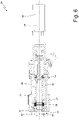
Figure 6 is a longitudinal section view of the reconfigurable conveyor drum ofFigure 3 ; and -
Figure 7 is a longitudinal section view of a variation of the reconfigurable conveyor drum ofFigure 3 . - In
Figure 1 ,number 1 denotes as a whole a feeding unit to feed components 2 (for example, pieces of filtering material or pieces of tobacco) which is part of a combining machine for the production of smoking articles (for example, new generation smokeless cigarettes, namely, without combustion) or of components for smoking articles (for example, filters for traditional cigarettes or for new generation cigarettes). - The
feeding unit 1 comprises ahopper 3 containing a mass ofcomponents 2 and afurther hopper 4 which is the twin of thehopper 3 and also contains a mass ofcomponents 2. According to a different embodiment, not illustrated, thefeeding unit 1 could comprise feeds of a flow ofcomponents 2 different from those of the hopper. - As illustrated in
Figures 1 and2 , thefeeding unit 1 comprises adrum 5 which is mounted so as to rotate around a rotation axis 6 (which is horizontal and perpendicular to the plane ofFigure 1 ) and is provided with a plurality ofsuction seats 7, which are formed on the side wall of thedrum 5 and are arranged with a single pitch P1 (namely, thesuction seats 7 of thedrum 5 are equally spaced and a constant distance equal to single pitch P1 is present between twoconsecutive suction seats 7 of the drum 5). Thesuction seats 7 of thedrum 5 receive thecomponents 2 coming from thehopper 3 at a feeding station S1 and receive thecomponents 2 coming from thehopper 4 at a feeding station S2 arranged downstream of the feeding station S1 relative to the rotation direction of thedrum 5. In the feeding station S1 thecomponents 2 coming from thehopper 3 have a double pitch P2 (which is exactly double the single pitch P1 of theseats 7 of the drum 5) and therefore immediately downstream of the feeding station S1 theseats 7 of thedrum 5 are alternately empty and full; also in the feeding station S2 thecomponents 2, coming from thehopper 4, have a double pitch P2 (which is exactly double the single pitch P1 of theseats 7 of the drum 5) and therefore in the feeding station S2 thecomponents 2, coming from thehopper 4, are inserted in theseats 7 of thedrum 5 left empty downstream of the feeding station S1. In other words, theseats 7 of thedrum 5 which have the single pitch P1 are half filled by thecomponents 2 coming from thehopper 3 in the feeding station S1 and the remaining half are filled by thecomponents 2 coming from thehopper 4 in the feeding station S2. - The
feeding unit 1 comprises atransport system 11 which is formed by a cascade (succession) of drums, picks up thecomponents 2 from thehopper 3 and releases thecomponents 2 to thedrum 5; in particular, thetransport system 11 ends at the feeding station S1 in which thetransport system 11 releases thecomponents 2 coming from thehopper 3 to theseats 7 of thedrum 5. Thetransport system 11 begins with a pickup drum that is directly coupled to a bottom of thehopper 3, namely, it is partially inserted in the bottom of thehopper 3, to cyclically pick up thecomponents 2 which are inside thehopper 3. Obviously, the drums of thetransport system 11 have suction seats which are arranged with the double pitch P2 (that is exactly double the single pitch P1 of thesuction seats 7 of the drum 5). The intermediate drums of the transport system 11 (namely, the drums arranged between the pickup drum 12 and the drum 5) can be simple transport drums (namely, they do not perform any type of operation or control on the components 2) or they can also be operating drums that perform an operation (for example a transversal cut, an overturning, an optical check, a pneumatic check ...) on thecomponents 2. - Similarly, the
feeding unit 1 comprises atransport system 13 that is formed by a cascade (succession) of drums, picks up thecomponents 2 from thehopper 4 and releases thecomponents 2 to thedrum 5; in particular, thetransport system 13 ends at the feeding station S2 in which thetransport system 13 releases thecomponents 2 coming from thehopper 4 to theseats 7 of thedrum 5. Thetransport system 13 begins with a pickup drum which is directly coupled to a bottom of thehopper 4, namely, it is partially inserted in the bottom of thehopper 4, to cyclically pick up thecomponents 2 that are inside thehopper 4. Obviously, the drums of thetransport system 13 have suction seats, which are arranged with the double pitch P2 (which is exactly double the single pitch P1 of thesuction seats 7 of the drum 5). The intermediate drums of the transport system 13 (namely, the drums located between the pickup drum and the drum 5) can be simple transport drums (namely, they do not perform any type of operation or control on the components 2) or they can also be operating drums that perform an operation (for example, a transversal cut, an overturning, an optical check, a pneumatic check ...) on thecomponents 2. - As illustrated in
Figures 1 and2 , the twotransport systems reconfigurable drums 24 and 25 (conveyors) which are arranged downstream of the respective pickup drums (namely, they receive thecomponents 2 directly from the respective pickup drums); in particular, each pickup drum is directly coupled to a bottom of therespective hopper respective hopper components 2 that are inside therespective hopper - The
reconfigurable drum 24 is mounted so as to rotate around a rotation axis 26 (which is horizontal and parallel to therotation axis 6 of the drum 5) and has a plurality ofsuction seats 27 that receive thecomponents 2 from thehopper 3; in particular, thesuction seats 27 of thereconfigurable drum 24 receive thecomponents 2 directly from the pickup drum coupled to the bottom of thehopper 3. - Similarly, the
reconfigurable drum 25 is mounted so as to rotate around a rotation axis 28 (which is horizontal and parallel to therotation axis 6 of the drum 5) and has a plurality ofsuction seats 29 that receive thecomponents 2 from thehopper 4; in particular, thesuction seats 29 of thereconfigurable drum 25 receive thecomponents 2 directly from the pickup drum coupled to the bottom of thehopper 4. - The
suction seats 7 of thedrum 5 receive thecomponents 2 coming from the hopper 3 (therefore from the reconfigurable drum 24) in the feeding station S1 and receive thecomponents 2 coming from the hopper 4 (therefore from the reconfigurable drum 25) in the feeding station S2. - The two
reconfigurable drums reconfigurable drum 24 alone will be described, being clear that what has been stated for thereconfigurable drum 24 is valid mutatis mutandis also for thereconfigurable drum 25. - As illustrated in
Figures 3 ,4 and 5 , thereconfigurable drum 24 comprises agroup 30 ofsuction seats 27 each designed to house acomponent 2 and agroup 31 ofseats 27 each designed to house acomponent 2; the twogroups seats 27 are identical to one another and therefore are each formed by the same number ofseats 27. Furthermore, thereconfigurable drum 24 comprises an actuator device 32 (illustrated inFigure 6 ) which is designed to impart a relative movement of thegroup 31 ofseats 27 relative to thegroup 30 ofseats 27 so as to move thegroup 31 ofseats 27 between a normal configuration (illustrated inFigure 4 ) which entails the double pitch P2 (normal) between theseats 27 and a special configuration (illustrated inFigure 5 ) which entails the single (special) pitch P1 between theseats 27 which is half the double (normal) pitch P2. In other words, the action of theactuator device 32 makes it possible to configure thereconfigurable drum 24 according to the normal configuration (illustrated inFigure 4 ) which entails the double (normal) pitch P2 between thecorresponding seats 27 or according to the special configuration (illustrated inFigure 5 ) which entails the single (special) pitch P1 which is half the double (normal) pitch P2 between theseats 27. - In the normal configuration (illustrated in
Figure 4 ) all theseats 27 of thegroup 31 are perfectly aligned with thecorresponding seats 27 of thegroup 30 and therefore eachseat 27 of thegroup 31 is nothing more than an extension (redundant addition) of acorresponding seat 27 of thegroup 30; consequently, in the normal configuration (illustrated inFigure 4 ) acomponent 2 is redundantly engaged both by aseat 27 of thegroup 30 and by aseat 27 of thegroup 31. Instead, in the special configuration (illustrated inFigure 5 ) all theseats 27 of thegroup 31 are unaligned and alternated with thecorresponding seats 27 of thegroup 30 and therefore eachseat 27 of thegroup 31 is designed to hold acomponent 2 which is not held by aseat 27 of thegroup 30; consequently, in the special configuration (illustrated inFigure 5 ) acomponent 2 is engaged (in a cantilever manner) only by aseat 27 of thegroup 30 or only by aseat 27 of thegroup 31. - In other words, by aligning the
seats 27 of thegroup 30 with theseats 27 of thegroup 31, the number ofcomponents 2 that can hold thereconfigurable drum 24 is equal to half the total number of seats 27 (as twoseats 27 are always aligned and therefore holding a same component 2), on the other hand, by un-aligning theseats 27 of thegroup 30 from theseats 27 of thegroup 31, the number ofcomponents 2 that thereconfigurable drum 24 can hold is equal to the total number of seats 27 (as acomponent 2 is always and only held by a single seat 27). Obviously, since the circumference of thereconfigurable drum 24 is always the same, by doubling the number ofseats 27 capable of independently holding acomponent 2, the pitch between theseats 27 is inevitably halved, which therefore passes from the double pitch P2 (normal) to the single pitch P1 (special) which is half the double (normal) pitch P2. - In summary, the
actuator device 32 moves thegroup 31 ofseats 27 between the special configuration (illustrated inFigure 5 ) in which theseats 27 of thegroup 31 are alternated with theseats 27 of thegroup 30 and are designed to housecorresponding components 2 which are not housed by the seats of thegroup 30 and the normal configuration (illustrated inFigure 4 ) in which eachseat 27 of thesecond group 31 is aligned with acorresponding seat 27 of thegroup 30 and therefore houses acomponent 2 also housed by thecorresponding seat 27 of thefirst group 30. - As illustrated in
Figures 3 ,4 and 5 , thegroup 30 ofseats 27 is axially staggered relative to thegroup 31 of seats 27 (namely, thegroup 30 ofseats 27 is arranged next to thegroup 31 of seats 27) and therefore thegroup 30 ofseats 27 can rotate relative to thegroup 31 ofseats 27 around therotation axis 26 so as to cause a reciprocal movement between thegroup 30 ofseats 27 and thegroup 31 ofseats 27. - According to what is illustrated in
Figures 6 and7 , thereconfigurable drum 24 comprises asupport ring 33 which supports thegroup 30 ofseats 27 and asupport ring 34 which is coaxial with thesupport ring 33, is mounted so as to rotate relative to thesupport ring 33 around therotation axis 26, and supports thegroup 31 ofseats 27. In particular, thesupport ring 33 is arranged radially, more externally than thesupport ring 34, namely, thesupport ring 34 is arranged radially, more internally than thesupport ring 33. - In the embodiment illustrated in
Figure 6 , thereconfigurable drum 24 comprises a single electric motor 35 which is mounted coaxially to therotation axis 26 and a commonmain body 36 which is mounted so as to rotate around therotation axis 26 and is set into rotation by the electric motor 35. Themain body 36 mounts thesupport ring 33 in a fixed manner so that thesupport ring 33 cannot make movements relative to themain body 36. Instead, themain body 36 rotatably mounts thesupport ring 34 so that thesupport ring 34 can rotate relative to themain body 36 around therotation axis 26; in addition, themain body 36 mounts theactuator device 32 which controls the rotation of thesupport ring 34 relative to the main body 36 (namely, relative to the support ring 33). - In particular, an
intermediate body 37 is mounted so as to rotate on the main body 36 (to rotate around the rotation axis 26) by means of the interposition ofrespective bearings 38 and theintermediate body 37 is integral with the support ring 34 (namely, it houses the support ring 34). - Consequently, the
support ring 33 is directly connected to themain body 36 so as to be completely integral with themain body 36 whereas thesupport ring 34 is mounted on themain body 36 by means of thebearings 38 so as to be free to rotate relative to the main body 36 (namely, relative to the support ring 33) around therotation axis 26. - In the embodiment illustrated in
Figure 6 , theactuator device 32 is designed to generate a linear movement, has anend 39 fixed in an eccentric position (relative to the rotation axis 26) to the main body 36 (therefore integral with the support ring 33), has anend 40 opposite theend 39 and fixed in an eccentric position (relative to the rotation axis 26) to thesupport ring 34, and is designed to vary the distance between theend 39 and theend 40 in order to generate a rotation between the main body 36 (namely, relative to the support ring 33) and thesupport ring 34. In this embodiment, theactuator device 32 can be a linear electric motor, a pneumatic actuator or a hydraulic actuator. - In the alternative embodiment illustrated in
Figure 7 , two differentelectric motors electric motor 41 only rotates thesupport ring 33 by means of atransmission 43 whereas theelectric motor 42 only rotates thesupport ring 34 by means of atransmission 44 in a completely independent and separate way from the electric motor 41 (namely, from the support ring 33). - In particular, the
transmission 43 comprises atoothed wheel 45 integral with ashaft 46 of theelectric motor 41 and atoothed wheel 47 which meshes with thetoothed wheel 45 and is integral with the main body 36 (which supports the support ring 33). Similarly, thetransmission 44 comprises atoothed wheel 48 integral with ashaft 49 of theelectric motor 42 and atoothed wheel 50 which meshes with thetoothed wheel 48 and is integral with the intermediate body 37 (which supports the support ring 34). - In the alternative embodiment illustrated in
Figure 7 , anactuator device 51 is envisaged, which is configured to vary the timing between the rotation movement generated by the electric motor 41 (which rotates the support ring 33) and the rotation movement generated by the electric motor 42 (which rotates the support ring 34). Consequently, if the rotational movements generated by theelectric motors seats 27 of thesupport ring 33 are and remain perfectly aligned with theseats 27 of the support ring 34 (as illustrated inFigure 4 ) whereas if the rotational movements generated by theelectric motors seats 27 of thesupport ring 33 are and remain unaligned with theseats 27 of the support ring 34 (as illustrated in theFigure 5 ). - With reference to
Figures 1 and2 , the operation of thefeeding unit 1 is described in the following both in the case of regular operation of bothhoppers hopper - As illustrated in
Figure 1 , in case of regular operation of bothhoppers components 2 coming from thehopper 3 are transferred (therefore by means of thetransport system 11 and of the reconfigurable drum 24) into half theseats 7 of thedrum 5 in the feeding station S1; at the same time, thecomponents 2 coming from thehopper 4 are transferred (therefore by means of thetransport system 13 and of the reconfigurable drum 25) in the feeding station S2 and into the remaining half theseats 7 of thedrum 5, so that in theseats 7 of thedrum 5 thecomponents 2 coming from thehopper 3 are alternated with thecomponents 2 coming from thehopper 4. - Namely, in half the
seats 7 of thedrum 5 thecomponents 2 arrive from thereconfigurable drum 24 and in the remaining half theseats 7 of thedrum 5 thecomponents 2 arrive from thereconfigurable drum 25 so that in theseats 7 of thedrum 5 thecomponents 2 coming from thereconfigurable drum 24 are alternated with thecomponents 2 coming from thereconfigurable drum 25. In this operating mode, thereconfigurable drums seats entire feeding unit 1 can operate at the nominal speed, namely, all the drums of thefeeding unit 1 can rotate at the maximum rotation speed envisaged by operation at nominal speed. - As illustrated in
Figure 2 , in case thehopper 3 stops, thereconfigurable drum 25 is configured according to the special configuration which entails a single (special) pitch P1 which is half the (double) normal pitch P2 between theseats 29 of thereconfigurable drum 25 and then (in the feeding station S2) in all theseats 7 of thedrum 5 thecomponents 2 are transferred from thereconfigurable drum 25 so that all theseats 7 of thedrum 5 are filled only withcomponents 2 coming from the reconfigurable drum 25 (therefore from the hopper 4) without leaving anyseat 7 of thedrum 5 empty. Namely, in the feeding station S2 in all theseats 7 of thedrum 5 thecomponents 2 coming from thehopper 4 are transferred (therefore by means of thereconfigurable drum 25 which is set in the special configuration) whereas in the feeding station S2 thecomponents 2 coming from thehopper 3 are not transferred (therefore by means of the reconfigurable drum 24) as thehopper 3 is stopped; consequently, all theseats 7 of thedrum 5 receive thecomponents 2 coming only from thehopper 4. In this operating mode, theentire feeding unit 1 can operate at a maximum of half the nominal speed, namely, all the drums of thefeeding unit 1 can rotate at a maximum of half the maximum rotation speed envisaged by operation at nominal speed. In other words, the drums of thefeeding unit 1 are made to rotate with a same normal (nominal) maximum rotation speed in case of regular operation of bothhoppers feeding unit 1 are rotated at a same special maximum rotation speed which is half the normal (nominal) maximum rotation speed in case ahopper - By operating in this way, starting from the drum 5 (namely, in the
drum 5 and in everything downstream of the drum 5) thecomponents 2 have the same pitch (namely, the single pitch PI) that they have when bothhoppers hopper 3 are completely masked; to obtain this result it is necessary to halve the maximum rotation speed of all the drums of thefeeding unit 1, namely, relative to the maximum rotation speed that would be possible when operating in nominal conditions (namely, when bothhoppers seats 7 of thedrum 5 are full (namely, they have respective components 2) and therefore to ensure that thefeeding unit 1 and the combining machine may have a completely normal operation (but obviously slowed down relative to the nominal capacity). It is important to note that the limitation on the productivity of the combining machine (namely, halving the productivity of the combining machine) is entirely logical and expected: if half thehoppers hoppers - What is described above in case the
hopper 3 stops, applies mutatis mutandis also in case of thehopper 4 stops. - According to a preferred embodiment, before configuring a
reconfigurable drum reconfigurable drum components 2 carried by thereconfigurable drum reconfigurable drum components 2 carried by theseats reconfigurable drum seats reconfigurable drum 24 or 25), thecomponents 2 would be destroyed by the relative movement between theseats reconfigurable drum - According to a possible embodiment, the
feeding unit 1 comprises for eachreconfigurable drum 24 or 25 a corresponding discarding station in which thecomponents 2 that are rejected by thereconfigurable drum reconfigurable drum components 2 to be separated from theseats reconfigurable drum components 2 towards the discarding station. - The
transport systems hoppers drum 5 or they can be shorter; in the latter case, thetransport systems Figures 1 and2 , and by thereconfigurable drums 24 and 25). In the embodiment illustrated inFigures 1 and2 , thetransport systems reconfigurable drums drum 5. - As previously mentioned,
Figure 1 illustrates the normal operation of the feeding unit 1 (namely, with bothhoppers Figure 2 illustrates the special operation of thefeeding unit 1 following stopping of the hopper 3: it should be noted that thereconfigurable drum 24 has the normal configuration (in which itsseats 27 have a double pitch P2) and is empty (thehopper 3 is stopped and therefore thereconfigurable drum 24 does not receive thecomponents 2 from the hopper 4) whereas thereconfigurable drum 25 has the special configuration (in which itsseats 29 have the single pitch PI) and is full (thehopper 4 is operating and therefore thereconfigurable drum 25 receives thecomponents 2 from the hopper 4); consequently, theseats 7 of thedrum 5, between the feeding station S1 and the feeding station S2, are all empty whereas theseats 7 of thedrum 5, downstream of the feeding station S2, are all full. - The
reconfigurable drums respective seats seats seats 27 or 29) or arranged side by side in order to function as if thereconfigurable drum seats 27 or 29 (normal mode with the double pitch P2 between theseats 27 or 29). In other words: on thereconfigurable drum 24 or 25 N seats 27 or 29 are present, all in the "active" position (namely, capable of transporting the components 2) when thereconfigurable drum seats reconfigurable drum - In the embodiments illustrated in the attached figures, half the
seats 27 or 29 (one yes and one no) are movable, and capable of performing a rotation of one pitch along the circumference of thereconfigurable drum 24 or 25: themovable seats 27 or 29 (belonging to the group 31), when in the active position are staggered relative to thenon-movable seats 27 or 29 (belonging to the group 30), whereas to become functionally "deactivated" themovable seats 27 or 29 (belonging to the group 31) can rotate and align with thenon-movable seats 27 or 29 (belonging to the group 30), effectively halving the number ofseats components 2. - The
movable seats 27 or 29 (belonging to the group 31) when aligned with thenon-movable seats 27 or 29 (belonging to the group 30) can (even if unnecessarily, namely in a redundant way) contribute to the holding and transport of thecomponents 2, or they could also be made completely deactivated (namely, without suction) and therefore do not contribute to the holding and transport of thecomponents 2. - In the embodiments illustrated in the attached figures, the
movable seats 27 or 29 (belonging to the group 31) perform a rotation around therotation axis non-movable seats 27 or 29 (belonging to the group 30); according to other embodiments not illustrated, themovable seats 27 or 29 (belonging to the group 31) could perform a different type of movement relative to thenon-movable seats 27 or 29 (belonging to the group 30), for example an axial translation (parallel to therotation axis 26 or 28) to move laterally away from the path of thecomponents 2 or a radial translation (perpendicular to therotation axis 26 or 28) to move radially away from the path of the components 2 (namely, collapse inside thereconfigurable drum 24 or 25). - The
reconfigurable drum feeding unit 1 for thecomponent 2 and, in this case, thereconfigurable drum groups seats groups seats seats seats group 30 may not be alternated withseats group 31. - The embodiments described herein can be combined with each other without departing from the scope of the present invention.
- The control method described above allows not to stop the
feeding unit 1 in case of jamming of ahopper feeding unit 1 belongs. This result is obtained thanks to the fact that the output of thefeeding unit 1 does not have empty seats even in case of jamming of ahopper
Claims (14)
- A method to control a feeding unit (1) to feed components (2) for smoking articles;the feeding unit (1) comprises: a first feed (3), which feeds a first flow of components (2), a second feed (4), which feeds a second flow of components (2), a first drum (24), which is provided with seats (27) receiving the components (2) from the first feed (3), a second drum (25), which is provided with seats (29) receiving the components (2) from the second feed (4), and a third drum (5), which is provided with seats (7) receiving the components (2) from the first drum (24) and from the second drum (25) ;the control method, in case of regular operation of both feeds (3, 4), comprises the steps of:configuring the first drum (24) and the second drum (25) according to a normal configuration, which entails a normal pitch (P2) between the corresponding seats (27, 29); andtransferring the components (2) coming from the first drum (24) into half the seats (7) of the third drum (5) and the components (2) coming from the second drum (25) into the remaining half of the seats (7) of the third drum (5) so that, in the seats (7) of the third drum (5), the components (2) coming from the first drum (24) are alternated with the components (2) coming from the second drum (25);the control method is characterized in that it comprises, in case the first feed (3) stops, the steps of:configuring the second drum (25) according to a special configuration, which entrails, between the seats (29) of the second drum (25), a special pitch (PI), which is smaller than, in particular half, the normal pitch (P2); andtransferring the components (2) coming from the second drum (25) into all the seats (7) of the third drum (5) so that all the seats (7) of the third drum (5) are filled with components (2) coming from the second drum (25) without leaving any seat (7) of the third drum (5) empty.
- The control method according to claim 1 and comprising the further steps of:causing the first drum (24), the second drum (25) and the third drum (5) to rotate with a same normal maximum rotation speed, in case of regular operation of both feeds (3, 4); andcausing the second drum (25) and the third drum (5) to rotate with a special maximum rotation speed, which is smaller than,in particular half, the normal maximum rotation speed, in case the first feed (3) stops.
- The control method according to claim 1 or 2, wherein the first/second drum (24, 25) comprises:a first group (30) of seats (27, 29), each designed to house a component (2);a second group (31) of seats (27, 29), each designed to house a component (2); andan actuator device (32; 51), which is designed to cause a relative movement of the second group (31) relative to the first group (30) in order to move the second group (31) from and to the special configuration, in which the seats (27, 29) of the second group (31) are alternated with the seats (27, 29) of the first group (30) and are designed to house corresponding components (2) which are preferably not housed by the seats (27, 29) of the first group (30).
- The control method according to claim 3, wherein:the first group (30) of seats (27, 29) is axially staggered relative to the second group (31) of seats (27, 29); andthe actuator device (32; 51) moves the second group (31) between the special configuration and the normal configuration, in which each first/second seat (27, 29) of the second group (31) is aligned with a corresponding first/second seat (27, 29) of the first group (30) and preferably houses a component (2) which is also housed by the corresponding first/second seat (27, 29) of the first group (30).
- The control method according to claim 3 or 4, wherein the first/second drum (24, 25) comprises:a first support ring (33), which supports the first group (30) of seats (27, 29); anda second support ring (34), which is coaxial to the first support ring (33), is mounted so as to rotate relative to the first support ring (33) and supports the second group (31) of seats (27, 29) .
- The control method according to one of the claims from 1 to 5 and comprising the further step of rejecting all the components (2) carried by the first/second drum (24, 25) so as to empty the first/second drum (24, 25) before configuring the first/second drum (24, 25), namely before changing the configuration of the first/second drum (24, 25).
- A combining machine for the production of smoking articles or of components of smoking articles; the combining machine comprising:a feeding unit (1) having: a first feed (3), which feeds a first flow of components (2), a second feed (4), which feeds a second flow of components (2), a first drum (24), which is provided with first seats (27) receiving the components (2) from the first feed (3), a second drum (25), which is provided with second seats (29) receiving the components (2) from the second feed (4), and a third drum (5), which is provided with third seats (7) receiving the components (2) from the first drum (24) and from the second drum (25); anda control system implementing the control method according to one of the claims from 1 to 6.
- A conveyor drum (24, 25) of a feeding unit (1) to feed components (2) for smoking articles; the conveyor drum can rotate around a central rotation axis (26; 28) and comprises a first group (30) of seats (27, 29), each designed to hold a corresponding component (2), and at least one second group (31) of seats (27, 29), each designed to hold a corresponding component (2);
the conveyor drum (24, 25) is characterized in that it comprises an actuator device (32; 51), which is designed to cause a relative movement of the second group (31) relative to the first group (30) in order to move the second group (31) between a normal configuration, in which each seat (27, 29) of the second group (31) is not suited to house a component that is not also housed by a seat (27, 29) of the first group (30), and a special configuration, in which each seat (27, 29) of the second group (31) is suited to house a component (2) that is not also housed by a seat (27, 29) of the first group (30). - The conveyor drum (24, 25) according to claim 8, wherein:the first group (30) of seats (27, 29) can be axially staggered relative to the second group (31) of seats (27, 29); andin the normal configuration, each seat (27, 29) of the second group (31) is aligned with a corresponding seat (27, 29) of the first group (30) and, therefore, houses a component (2) which is also housed by the corresponding seat (27, 29) of the first group (30).
- The conveyor drum (24, 25) according to claim 8 or 9 and comprising:a first support ring (33), which supports the first group (30) of seats (27, 29); anda second support ring (34), which is coaxial to the first support ring (33), is mounted so as to rotate relative to the first support ring (33) and supports the second group (31) of seats (27, 29).
- The conveyor drum (24, 25) according to claim 10 and comprising:an electric motor (35); anda common main body (36), which is mounted so as to rotate around the rotation axis (26, 28), is caused to rotate by the electric motor (35), bears the first support ring (33) in a fixed manner so that the first support ring (33) cannot make movements relative to the main body (36), bears the second support ring (34) in a rotary manner so that the second support ring (34) can rotate relative to the main body (36) around the rotation axis (26, 28) and bears the actuator device (32; 51), which controls the rotation of the second support ring (34) relative to the main body (36).
- The conveyor drum (24, 25) according to claim 11, wherein:the first support ring (33) is directly connected to the main body (36) so as to be completely integral to the main body (36);the second support ring (34) is mounted on the main body (36) by means of bearings (38) so as to be free to rotate relative to the main body (36); andthe actuator device (32) is designed to generate a linear movement, has a first end (39), which is fixed to the main body (36), has a second end (40), which is opposite the first end (39) and is fixed to the second support ring (34), and is designed to change the pitch between the first end (39) and the second end (40) so as to generate a rotation between the main body (36) and the second support ring (34).
- The conveyor drum (24, 25) according to claim 10 and comprising:a first electric motor (41), which causes the rotation of the first support ring (33); anda second electric motor (42), which causes the rotation of the second support ring (34) completely independently of and separately from the first electric motor (41).
- The conveyor drum (24, 25) according to figure 13, wherein the actuator device (51) is configured to change the timing between the rotation movement generated by the first electric motor (41) and the rotation movement generated by the second electric motor (42).
Applications Claiming Priority (1)
| Application Number | Priority Date | Filing Date | Title |
|---|---|---|---|
| IT102020000023959A IT202000023959A1 (en) | 2020-10-12 | 2020-10-12 | METHOD OF CONTROLLING A FEEDING UNIT FOR FEEDING COMPONENTS FOR SMOKING ITEMS AND DRUM CONVEYOR OF A FEEDING UNIT FOR FEEDING COMPONENTS FOR SMOKING ITEMS |
Publications (3)
| Publication Number | Publication Date |
|---|---|
| EP3984382A2 true EP3984382A2 (en) | 2022-04-20 |
| EP3984382A3 EP3984382A3 (en) | 2022-05-18 |
| EP3984382B1 EP3984382B1 (en) | 2023-12-06 |
Family
ID=74068420
Family Applications (1)
| Application Number | Title | Priority Date | Filing Date |
|---|---|---|---|
| EP21202280.0A Active EP3984382B1 (en) | 2020-10-12 | 2021-10-12 | Method to control a feeding unit to feed components for smoking articles and conveyor drum of a feeding unit to feed components for smoking articles |
Country Status (3)
| Country | Link |
|---|---|
| EP (1) | EP3984382B1 (en) |
| IT (1) | IT202000023959A1 (en) |
| PL (1) | PL3984382T3 (en) |
Cited By (2)
| Publication number | Priority date | Publication date | Assignee | Title |
|---|---|---|---|---|
| CN115606839A (en) * | 2022-09-08 | 2023-01-17 | 常德烟草机械有限责任公司 | Multi-section bar microspur separating and conveying device and base rod differential wheel thereof |
| IT202300019281A1 (en) * | 2023-09-20 | 2025-03-20 | Gd Spa | METHOD FOR MANAGING A PROCESSING LINE FOR BAR-SHAPED ITEMS AND PROCESSING LINE FOR BAR-SHAPED ITEMS |
Citations (1)
| Publication number | Priority date | Publication date | Assignee | Title |
|---|---|---|---|---|
| EP3542650A2 (en) | 2018-03-22 | 2019-09-25 | Hauni Maschinenbau GmbH | Conveying and cutting device for rod-shaped tobacco articles |
Family Cites Families (2)
| Publication number | Priority date | Publication date | Assignee | Title |
|---|---|---|---|---|
| DE102011115713A1 (en) * | 2011-10-12 | 2013-04-18 | Hauni Maschinenbau Ag | Transfer drum for a machine for the production of products of the tobacco processing industry |
| DE102019101988A1 (en) * | 2019-01-28 | 2020-07-30 | Hauni Maschinenbau Gmbh | Manufacture of rod-shaped smoking products |
-
2020
- 2020-10-12 IT IT102020000023959A patent/IT202000023959A1/en unknown
-
2021
- 2021-10-12 EP EP21202280.0A patent/EP3984382B1/en active Active
- 2021-10-12 PL PL21202280.0T patent/PL3984382T3/en unknown
Patent Citations (1)
| Publication number | Priority date | Publication date | Assignee | Title |
|---|---|---|---|---|
| EP3542650A2 (en) | 2018-03-22 | 2019-09-25 | Hauni Maschinenbau GmbH | Conveying and cutting device for rod-shaped tobacco articles |
Cited By (4)
| Publication number | Priority date | Publication date | Assignee | Title |
|---|---|---|---|---|
| CN115606839A (en) * | 2022-09-08 | 2023-01-17 | 常德烟草机械有限责任公司 | Multi-section bar microspur separating and conveying device and base rod differential wheel thereof |
| CN115606839B (en) * | 2022-09-08 | 2024-01-19 | 常德烟草机械有限责任公司 | Multi-section bar micro-distance separating and conveying device and base bar micro-wheel thereof |
| IT202300019281A1 (en) * | 2023-09-20 | 2025-03-20 | Gd Spa | METHOD FOR MANAGING A PROCESSING LINE FOR BAR-SHAPED ITEMS AND PROCESSING LINE FOR BAR-SHAPED ITEMS |
| WO2025062308A1 (en) * | 2023-09-20 | 2025-03-27 | G.D S.P.A. | Line for processing rod-shped articles |
Also Published As
| Publication number | Publication date |
|---|---|
| EP3984382A3 (en) | 2022-05-18 |
| PL3984382T3 (en) | 2024-04-15 |
| EP3984382B1 (en) | 2023-12-06 |
| IT202000023959A1 (en) | 2022-04-12 |
Similar Documents
| Publication | Publication Date | Title |
|---|---|---|
| EP3984382B1 (en) | Method to control a feeding unit to feed components for smoking articles and conveyor drum of a feeding unit to feed components for smoking articles | |
| JP6438063B2 (en) | Improvements related to smoking product assembly | |
| JP5882616B2 (en) | Mechanical apparatus and method for manufacturing composite filters | |
| US8443964B2 (en) | Adjustable reservoir for rod-like articles | |
| EP0580150B1 (en) | Method of producing filter-tipped cigarettes | |
| EP2505086A1 (en) | Transfer or feed drum, with radial-arm-mounted operating heads, for filter or cigarette portions | |
| US5366064A (en) | Product manufacturing method, particularly for tobacco items | |
| JP6048846B2 (en) | Method for producing cigarette with filter and filter mounting machine | |
| CN112236046B (en) | Filter segment collecting device and method for collecting filter segments of tobacco processing industry | |
| US20040261801A1 (en) | Device for wrapping groups of filter segments with a wrapping material for producing multi-segment filters of the tobacco industry and multi-segment filter production device | |
| KR101946198B1 (en) | Electronic cigarette manufacturing apparatus | |
| EP3197302A1 (en) | Unit and method for recovering tobacco from rejected products in machines for making smokers' articles | |
| US4406197A (en) | Method and apparatus for transporting rod-shaped articles | |
| EP3984381B1 (en) | Method to control a feeding unit to feed components for smoking articles | |
| EP3136883B1 (en) | A tobacco industry rod assembly apparatus | |
| EP1883319B1 (en) | A unit for transferring sticks of rod material used to manufacture tobacco products | |
| EP0885808B1 (en) | Machine for packing groups of cigarettes | |
| EP1800552A1 (en) | A unit for conveying tobacco products | |
| RU2776519C2 (en) | Retrofitting device, instrument for manufacture of multi-segment rods and method for manufacture of multi-segment rods | |
| EP4444117A1 (en) | Method and system of manufacturing multisegment articles | |
| HK1233454B (en) | A tobacco industry rod assembly apparatus | |
| HK1233454A1 (en) | A tobacco industry rod assembly apparatus |
Legal Events
| Date | Code | Title | Description |
|---|---|---|---|
| PUAI | Public reference made under article 153(3) epc to a published international application that has entered the european phase |
Free format text: ORIGINAL CODE: 0009012 |
|
| STAA | Information on the status of an ep patent application or granted ep patent |
Free format text: STATUS: THE APPLICATION HAS BEEN PUBLISHED |
|
| PUAL | Search report despatched |
Free format text: ORIGINAL CODE: 0009013 |
|
| AK | Designated contracting states |
Kind code of ref document: A2 Designated state(s): AL AT BE BG CH CY CZ DE DK EE ES FI FR GB GR HR HU IE IS IT LI LT LU LV MC MK MT NL NO PL PT RO RS SE SI SK SM TR |
|
| AK | Designated contracting states |
Kind code of ref document: A3 Designated state(s): AL AT BE BG CH CY CZ DE DK EE ES FI FR GB GR HR HU IE IS IT LI LT LU LV MC MK MT NL NO PL PT RO RS SE SI SK SM TR |
|
| RIC1 | Information provided on ipc code assigned before grant |
Ipc: A24D 3/02 20060101ALI20220413BHEP Ipc: A24C 5/32 20060101ALI20220413BHEP Ipc: A24C 5/47 20060101AFI20220413BHEP |
|
| STAA | Information on the status of an ep patent application or granted ep patent |
Free format text: STATUS: REQUEST FOR EXAMINATION WAS MADE |
|
| 17P | Request for examination filed |
Effective date: 20221118 |
|
| RBV | Designated contracting states (corrected) |
Designated state(s): AL AT BE BG CH CY CZ DE DK EE ES FI FR GB GR HR HU IE IS IT LI LT LU LV MC MK MT NL NO PL PT RO RS SE SI SK SM TR |
|
| GRAP | Despatch of communication of intention to grant a patent |
Free format text: ORIGINAL CODE: EPIDOSNIGR1 |
|
| STAA | Information on the status of an ep patent application or granted ep patent |
Free format text: STATUS: GRANT OF PATENT IS INTENDED |
|
| INTG | Intention to grant announced |
Effective date: 20230516 |
|
| P01 | Opt-out of the competence of the unified patent court (upc) registered |
Effective date: 20230529 |
|
| GRAS | Grant fee paid |
Free format text: ORIGINAL CODE: EPIDOSNIGR3 |
|
| GRAA | (expected) grant |
Free format text: ORIGINAL CODE: 0009210 |
|
| STAA | Information on the status of an ep patent application or granted ep patent |
Free format text: STATUS: THE PATENT HAS BEEN GRANTED |
|
| AK | Designated contracting states |
Kind code of ref document: B1 Designated state(s): AL AT BE BG CH CY CZ DE DK EE ES FI FR GB GR HR HU IE IS IT LI LT LU LV MC MK MT NL NO PL PT RO RS SE SI SK SM TR |
|
| REG | Reference to a national code |
Ref country code: GB Ref legal event code: FG4D |
|
| REG | Reference to a national code |
Ref country code: CH Ref legal event code: EP |
|
| REG | Reference to a national code |
Ref country code: DE Ref legal event code: R096 Ref document number: 602021007454 Country of ref document: DE |
|
| REG | Reference to a national code |
Ref country code: IE Ref legal event code: FG4D |
|
| REG | Reference to a national code |
Ref country code: NL Ref legal event code: FP |
|
| REG | Reference to a national code |
Ref country code: LT Ref legal event code: MG9D |
|
| PG25 | Lapsed in a contracting state [announced via postgrant information from national office to epo] |
Ref country code: GR Free format text: LAPSE BECAUSE OF FAILURE TO SUBMIT A TRANSLATION OF THE DESCRIPTION OR TO PAY THE FEE WITHIN THE PRESCRIBED TIME-LIMIT Effective date: 20240307 |
|
| PG25 | Lapsed in a contracting state [announced via postgrant information from national office to epo] |
Ref country code: LT Free format text: LAPSE BECAUSE OF FAILURE TO SUBMIT A TRANSLATION OF THE DESCRIPTION OR TO PAY THE FEE WITHIN THE PRESCRIBED TIME-LIMIT Effective date: 20231206 |
|
| PG25 | Lapsed in a contracting state [announced via postgrant information from national office to epo] |
Ref country code: ES Free format text: LAPSE BECAUSE OF FAILURE TO SUBMIT A TRANSLATION OF THE DESCRIPTION OR TO PAY THE FEE WITHIN THE PRESCRIBED TIME-LIMIT Effective date: 20231206 |
|
| PG25 | Lapsed in a contracting state [announced via postgrant information from national office to epo] |
Ref country code: LT Free format text: LAPSE BECAUSE OF FAILURE TO SUBMIT A TRANSLATION OF THE DESCRIPTION OR TO PAY THE FEE WITHIN THE PRESCRIBED TIME-LIMIT Effective date: 20231206 Ref country code: GR Free format text: LAPSE BECAUSE OF FAILURE TO SUBMIT A TRANSLATION OF THE DESCRIPTION OR TO PAY THE FEE WITHIN THE PRESCRIBED TIME-LIMIT Effective date: 20240307 Ref country code: ES Free format text: LAPSE BECAUSE OF FAILURE TO SUBMIT A TRANSLATION OF THE DESCRIPTION OR TO PAY THE FEE WITHIN THE PRESCRIBED TIME-LIMIT Effective date: 20231206 Ref country code: BG Free format text: LAPSE BECAUSE OF FAILURE TO SUBMIT A TRANSLATION OF THE DESCRIPTION OR TO PAY THE FEE WITHIN THE PRESCRIBED TIME-LIMIT Effective date: 20240306 |
|
| REG | Reference to a national code |
Ref country code: AT Ref legal event code: MK05 Ref document number: 1637531 Country of ref document: AT Kind code of ref document: T Effective date: 20231206 |
|
| PG25 | Lapsed in a contracting state [announced via postgrant information from national office to epo] |
Ref country code: SE Free format text: LAPSE BECAUSE OF FAILURE TO SUBMIT A TRANSLATION OF THE DESCRIPTION OR TO PAY THE FEE WITHIN THE PRESCRIBED TIME-LIMIT Effective date: 20231206 Ref country code: RS Free format text: LAPSE BECAUSE OF FAILURE TO SUBMIT A TRANSLATION OF THE DESCRIPTION OR TO PAY THE FEE WITHIN THE PRESCRIBED TIME-LIMIT Effective date: 20231206 Ref country code: NO Free format text: LAPSE BECAUSE OF FAILURE TO SUBMIT A TRANSLATION OF THE DESCRIPTION OR TO PAY THE FEE WITHIN THE PRESCRIBED TIME-LIMIT Effective date: 20240306 Ref country code: LV Free format text: LAPSE BECAUSE OF FAILURE TO SUBMIT A TRANSLATION OF THE DESCRIPTION OR TO PAY THE FEE WITHIN THE PRESCRIBED TIME-LIMIT Effective date: 20231206 Ref country code: HR Free format text: LAPSE BECAUSE OF FAILURE TO SUBMIT A TRANSLATION OF THE DESCRIPTION OR TO PAY THE FEE WITHIN THE PRESCRIBED TIME-LIMIT Effective date: 20231206 |
|
| PG25 | Lapsed in a contracting state [announced via postgrant information from national office to epo] |
Ref country code: IS Free format text: LAPSE BECAUSE OF FAILURE TO SUBMIT A TRANSLATION OF THE DESCRIPTION OR TO PAY THE FEE WITHIN THE PRESCRIBED TIME-LIMIT Effective date: 20240406 |
|
| PG25 | Lapsed in a contracting state [announced via postgrant information from national office to epo] |
Ref country code: CZ Free format text: LAPSE BECAUSE OF FAILURE TO SUBMIT A TRANSLATION OF THE DESCRIPTION OR TO PAY THE FEE WITHIN THE PRESCRIBED TIME-LIMIT Effective date: 20231206 Ref country code: AT Free format text: LAPSE BECAUSE OF FAILURE TO SUBMIT A TRANSLATION OF THE DESCRIPTION OR TO PAY THE FEE WITHIN THE PRESCRIBED TIME-LIMIT Effective date: 20231206 |
|
| PG25 | Lapsed in a contracting state [announced via postgrant information from national office to epo] |
Ref country code: SK Free format text: LAPSE BECAUSE OF FAILURE TO SUBMIT A TRANSLATION OF THE DESCRIPTION OR TO PAY THE FEE WITHIN THE PRESCRIBED TIME-LIMIT Effective date: 20231206 |
|
| PG25 | Lapsed in a contracting state [announced via postgrant information from national office to epo] |
Ref country code: SM Free format text: LAPSE BECAUSE OF FAILURE TO SUBMIT A TRANSLATION OF THE DESCRIPTION OR TO PAY THE FEE WITHIN THE PRESCRIBED TIME-LIMIT Effective date: 20231206 Ref country code: SK Free format text: LAPSE BECAUSE OF FAILURE TO SUBMIT A TRANSLATION OF THE DESCRIPTION OR TO PAY THE FEE WITHIN THE PRESCRIBED TIME-LIMIT Effective date: 20231206 Ref country code: RO Free format text: LAPSE BECAUSE OF FAILURE TO SUBMIT A TRANSLATION OF THE DESCRIPTION OR TO PAY THE FEE WITHIN THE PRESCRIBED TIME-LIMIT Effective date: 20231206 Ref country code: IT Free format text: LAPSE BECAUSE OF FAILURE TO SUBMIT A TRANSLATION OF THE DESCRIPTION OR TO PAY THE FEE WITHIN THE PRESCRIBED TIME-LIMIT Effective date: 20231206 Ref country code: IS Free format text: LAPSE BECAUSE OF FAILURE TO SUBMIT A TRANSLATION OF THE DESCRIPTION OR TO PAY THE FEE WITHIN THE PRESCRIBED TIME-LIMIT Effective date: 20240406 Ref country code: EE Free format text: LAPSE BECAUSE OF FAILURE TO SUBMIT A TRANSLATION OF THE DESCRIPTION OR TO PAY THE FEE WITHIN THE PRESCRIBED TIME-LIMIT Effective date: 20231206 Ref country code: CZ Free format text: LAPSE BECAUSE OF FAILURE TO SUBMIT A TRANSLATION OF THE DESCRIPTION OR TO PAY THE FEE WITHIN THE PRESCRIBED TIME-LIMIT Effective date: 20231206 Ref country code: AT Free format text: LAPSE BECAUSE OF FAILURE TO SUBMIT A TRANSLATION OF THE DESCRIPTION OR TO PAY THE FEE WITHIN THE PRESCRIBED TIME-LIMIT Effective date: 20231206 |
|
| PG25 | Lapsed in a contracting state [announced via postgrant information from national office to epo] |
Ref country code: PT Free format text: LAPSE BECAUSE OF FAILURE TO SUBMIT A TRANSLATION OF THE DESCRIPTION OR TO PAY THE FEE WITHIN THE PRESCRIBED TIME-LIMIT Effective date: 20240408 |
|
| PG25 | Lapsed in a contracting state [announced via postgrant information from national office to epo] |
Ref country code: PT Free format text: LAPSE BECAUSE OF FAILURE TO SUBMIT A TRANSLATION OF THE DESCRIPTION OR TO PAY THE FEE WITHIN THE PRESCRIBED TIME-LIMIT Effective date: 20240408 |
|
| REG | Reference to a national code |
Ref country code: DE Ref legal event code: R097 Ref document number: 602021007454 Country of ref document: DE |
|
| PG25 | Lapsed in a contracting state [announced via postgrant information from national office to epo] |
Ref country code: DK Free format text: LAPSE BECAUSE OF FAILURE TO SUBMIT A TRANSLATION OF THE DESCRIPTION OR TO PAY THE FEE WITHIN THE PRESCRIBED TIME-LIMIT Effective date: 20231206 |
|
| PLBE | No opposition filed within time limit |
Free format text: ORIGINAL CODE: 0009261 |
|
| STAA | Information on the status of an ep patent application or granted ep patent |
Free format text: STATUS: NO OPPOSITION FILED WITHIN TIME LIMIT |
|
| PG25 | Lapsed in a contracting state [announced via postgrant information from national office to epo] |
Ref country code: SI Free format text: LAPSE BECAUSE OF FAILURE TO SUBMIT A TRANSLATION OF THE DESCRIPTION OR TO PAY THE FEE WITHIN THE PRESCRIBED TIME-LIMIT Effective date: 20231206 |
|
| PG25 | Lapsed in a contracting state [announced via postgrant information from national office to epo] |
Ref country code: SI Free format text: LAPSE BECAUSE OF FAILURE TO SUBMIT A TRANSLATION OF THE DESCRIPTION OR TO PAY THE FEE WITHIN THE PRESCRIBED TIME-LIMIT Effective date: 20231206 Ref country code: DK Free format text: LAPSE BECAUSE OF FAILURE TO SUBMIT A TRANSLATION OF THE DESCRIPTION OR TO PAY THE FEE WITHIN THE PRESCRIBED TIME-LIMIT Effective date: 20231206 |
|
| 26N | No opposition filed |
Effective date: 20240909 |
|
| REG | Reference to a national code |
Ref country code: CH Ref legal event code: PL |
|
| PG25 | Lapsed in a contracting state [announced via postgrant information from national office to epo] |
Ref country code: MC Free format text: LAPSE BECAUSE OF FAILURE TO SUBMIT A TRANSLATION OF THE DESCRIPTION OR TO PAY THE FEE WITHIN THE PRESCRIBED TIME-LIMIT Effective date: 20231206 |
|
| PG25 | Lapsed in a contracting state [announced via postgrant information from national office to epo] |
Ref country code: BE Free format text: LAPSE BECAUSE OF NON-PAYMENT OF DUE FEES Effective date: 20241031 Ref country code: LU Free format text: LAPSE BECAUSE OF NON-PAYMENT OF DUE FEES Effective date: 20241012 |
|
| PG25 | Lapsed in a contracting state [announced via postgrant information from national office to epo] |
Ref country code: FR Free format text: LAPSE BECAUSE OF NON-PAYMENT OF DUE FEES Effective date: 20241031 |
|
| PG25 | Lapsed in a contracting state [announced via postgrant information from national office to epo] |
Ref country code: CH Free format text: LAPSE BECAUSE OF NON-PAYMENT OF DUE FEES Effective date: 20241031 |
|
| REG | Reference to a national code |
Ref country code: BE Ref legal event code: MM Effective date: 20241031 |
|
| PG25 | Lapsed in a contracting state [announced via postgrant information from national office to epo] |
Ref country code: FI Free format text: LAPSE BECAUSE OF FAILURE TO SUBMIT A TRANSLATION OF THE DESCRIPTION OR TO PAY THE FEE WITHIN THE PRESCRIBED TIME-LIMIT Effective date: 20231207 |
|
| PGFP | Annual fee paid to national office [announced via postgrant information from national office to epo] |
Ref country code: PL Payment date: 20250918 Year of fee payment: 5 |
|
| PG25 | Lapsed in a contracting state [announced via postgrant information from national office to epo] |
Ref country code: IE Free format text: LAPSE BECAUSE OF NON-PAYMENT OF DUE FEES Effective date: 20241012 |
|
| PGFP | Annual fee paid to national office [announced via postgrant information from national office to epo] |
Ref country code: NL Payment date: 20251026 Year of fee payment: 5 |
|
| PGFP | Annual fee paid to national office [announced via postgrant information from national office to epo] |
Ref country code: DE Payment date: 20251029 Year of fee payment: 5 |
|
| PG25 | Lapsed in a contracting state [announced via postgrant information from national office to epo] |
Ref country code: CY Free format text: LAPSE BECAUSE OF FAILURE TO SUBMIT A TRANSLATION OF THE DESCRIPTION OR TO PAY THE FEE WITHIN THE PRESCRIBED TIME-LIMIT; INVALID AB INITIO Effective date: 20211012 |
|
| PG25 | Lapsed in a contracting state [announced via postgrant information from national office to epo] |
Ref country code: HU Free format text: LAPSE BECAUSE OF FAILURE TO SUBMIT A TRANSLATION OF THE DESCRIPTION OR TO PAY THE FEE WITHIN THE PRESCRIBED TIME-LIMIT; INVALID AB INITIO Effective date: 20211012 |