EP3983754B1 - Terrainsensitive routenplanung - Google Patents
Terrainsensitive routenplanung Download PDFInfo
- Publication number
- EP3983754B1 EP3983754B1 EP20840698.3A EP20840698A EP3983754B1 EP 3983754 B1 EP3983754 B1 EP 3983754B1 EP 20840698 A EP20840698 A EP 20840698A EP 3983754 B1 EP3983754 B1 EP 3983754B1
- Authority
- EP
- European Patent Office
- Prior art keywords
- vehicle
- route
- database
- terrain
- risk
- Prior art date
- Legal status (The legal status is an assumption and is not a legal conclusion. Google has not performed a legal analysis and makes no representation as to the accuracy of the status listed.)
- Active
Links
Images
Classifications
-
- G—PHYSICS
- G01—MEASURING; TESTING
- G01C—MEASURING DISTANCES, LEVELS OR BEARINGS; SURVEYING; NAVIGATION; GYROSCOPIC INSTRUMENTS; PHOTOGRAMMETRY OR VIDEOGRAMMETRY
- G01C21/00—Navigation; Navigational instruments not provided for in groups G01C1/00 - G01C19/00
- G01C21/26—Navigation; Navigational instruments not provided for in groups G01C1/00 - G01C19/00 specially adapted for navigation in a road network
- G01C21/28—Navigation; Navigational instruments not provided for in groups G01C1/00 - G01C19/00 specially adapted for navigation in a road network with correlation of data from several navigational instruments
- G01C21/30—Map- or contour-matching
-
- G—PHYSICS
- G01—MEASURING; TESTING
- G01C—MEASURING DISTANCES, LEVELS OR BEARINGS; SURVEYING; NAVIGATION; GYROSCOPIC INSTRUMENTS; PHOTOGRAMMETRY OR VIDEOGRAMMETRY
- G01C21/00—Navigation; Navigational instruments not provided for in groups G01C1/00 - G01C19/00
- G01C21/26—Navigation; Navigational instruments not provided for in groups G01C1/00 - G01C19/00 specially adapted for navigation in a road network
- G01C21/28—Navigation; Navigational instruments not provided for in groups G01C1/00 - G01C19/00 specially adapted for navigation in a road network with correlation of data from several navigational instruments
-
- B—PERFORMING OPERATIONS; TRANSPORTING
- B60—VEHICLES IN GENERAL
- B60W—CONJOINT CONTROL OF VEHICLE SUB-UNITS OF DIFFERENT TYPE OR DIFFERENT FUNCTION; CONTROL SYSTEMS SPECIALLY ADAPTED FOR HYBRID VEHICLES; ROAD VEHICLE DRIVE CONTROL SYSTEMS FOR PURPOSES NOT RELATED TO THE CONTROL OF A PARTICULAR SUB-UNIT
- B60W40/00—Estimation or calculation of non-directly measurable driving parameters for road vehicle drive control systems not related to the control of a particular sub unit, e.g. by using mathematical models
- B60W40/02—Estimation or calculation of non-directly measurable driving parameters for road vehicle drive control systems not related to the control of a particular sub unit, e.g. by using mathematical models related to ambient conditions
- B60W40/06—Road conditions
-
- G—PHYSICS
- G01—MEASURING; TESTING
- G01C—MEASURING DISTANCES, LEVELS OR BEARINGS; SURVEYING; NAVIGATION; GYROSCOPIC INSTRUMENTS; PHOTOGRAMMETRY OR VIDEOGRAMMETRY
- G01C21/00—Navigation; Navigational instruments not provided for in groups G01C1/00 - G01C19/00
- G01C21/20—Instruments for performing navigational calculations
-
- G—PHYSICS
- G01—MEASURING; TESTING
- G01C—MEASURING DISTANCES, LEVELS OR BEARINGS; SURVEYING; NAVIGATION; GYROSCOPIC INSTRUMENTS; PHOTOGRAMMETRY OR VIDEOGRAMMETRY
- G01C21/00—Navigation; Navigational instruments not provided for in groups G01C1/00 - G01C19/00
- G01C21/26—Navigation; Navigational instruments not provided for in groups G01C1/00 - G01C19/00 specially adapted for navigation in a road network
- G01C21/34—Route searching; Route guidance
- G01C21/3446—Details of route searching algorithms, e.g. Dijkstra, A*, arc-flags or using precalculated routes
-
- G—PHYSICS
- G01—MEASURING; TESTING
- G01C—MEASURING DISTANCES, LEVELS OR BEARINGS; SURVEYING; NAVIGATION; GYROSCOPIC INSTRUMENTS; PHOTOGRAMMETRY OR VIDEOGRAMMETRY
- G01C21/00—Navigation; Navigational instruments not provided for in groups G01C1/00 - G01C19/00
- G01C21/26—Navigation; Navigational instruments not provided for in groups G01C1/00 - G01C19/00 specially adapted for navigation in a road network
- G01C21/34—Route searching; Route guidance
- G01C21/3453—Special cost functions, i.e. other than distance or default speed limit of road segments
- G01C21/3461—Preferred or disfavoured areas, e.g. dangerous zones, toll or emission zones, intersections, manoeuvre types or segments such as motorways, toll roads or ferries
-
- G—PHYSICS
- G01—MEASURING; TESTING
- G01C—MEASURING DISTANCES, LEVELS OR BEARINGS; SURVEYING; NAVIGATION; GYROSCOPIC INSTRUMENTS; PHOTOGRAMMETRY OR VIDEOGRAMMETRY
- G01C21/00—Navigation; Navigational instruments not provided for in groups G01C1/00 - G01C19/00
- G01C21/26—Navigation; Navigational instruments not provided for in groups G01C1/00 - G01C19/00 specially adapted for navigation in a road network
- G01C21/34—Route searching; Route guidance
- G01C21/36—Input/output arrangements for on-board computers
- G01C21/3697—Output of additional, non-guidance related information, e.g. low fuel level
-
- G—PHYSICS
- G01—MEASURING; TESTING
- G01C—MEASURING DISTANCES, LEVELS OR BEARINGS; SURVEYING; NAVIGATION; GYROSCOPIC INSTRUMENTS; PHOTOGRAMMETRY OR VIDEOGRAMMETRY
- G01C21/00—Navigation; Navigational instruments not provided for in groups G01C1/00 - G01C19/00
- G01C21/38—Electronic maps specially adapted for navigation; Updating thereof
- G01C21/3804—Creation or updating of map data
- G01C21/3807—Creation or updating of map data characterised by the type of data
- G01C21/3826—Terrain data
-
- G—PHYSICS
- G01—MEASURING; TESTING
- G01S—RADIO DIRECTION-FINDING; RADIO NAVIGATION; DETERMINING DISTANCE OR VELOCITY BY USE OF RADIO WAVES; LOCATING OR PRESENCE-DETECTING BY USE OF THE REFLECTION OR RERADIATION OF RADIO WAVES; ANALOGOUS ARRANGEMENTS USING OTHER WAVES
- G01S13/00—Systems using the reflection or reradiation of radio waves, e.g. radar systems; Analogous systems using reflection or reradiation of waves whose nature or wavelength is irrelevant or unspecified
- G01S13/02—Systems using reflection of radio waves, e.g. primary radar systems; Analogous systems
- G01S13/50—Systems of measurement based on relative movement of target
- G01S13/58—Velocity or trajectory determination systems; Sense-of-movement determination systems
- G01S13/60—Velocity or trajectory determination systems; Sense-of-movement determination systems wherein the transmitter and receiver are mounted on the moving object, e.g. for determining ground speed, drift angle, ground track
- G01S13/605—Velocity or trajectory determination systems; Sense-of-movement determination systems wherein the transmitter and receiver are mounted on the moving object, e.g. for determining ground speed, drift angle, ground track using a pattern, backscattered from the ground, to determine speed or drift by measuring the time required to cover a fixed distance
-
- G—PHYSICS
- G01—MEASURING; TESTING
- G01S—RADIO DIRECTION-FINDING; RADIO NAVIGATION; DETERMINING DISTANCE OR VELOCITY BY USE OF RADIO WAVES; LOCATING OR PRESENCE-DETECTING BY USE OF THE REFLECTION OR RERADIATION OF RADIO WAVES; ANALOGOUS ARRANGEMENTS USING OTHER WAVES
- G01S13/00—Systems using the reflection or reradiation of radio waves, e.g. radar systems; Analogous systems using reflection or reradiation of waves whose nature or wavelength is irrelevant or unspecified
- G01S13/88—Radar or analogous systems specially adapted for specific applications
- G01S13/885—Radar or analogous systems specially adapted for specific applications for ground probing
-
- G—PHYSICS
- G01—MEASURING; TESTING
- G01S—RADIO DIRECTION-FINDING; RADIO NAVIGATION; DETERMINING DISTANCE OR VELOCITY BY USE OF RADIO WAVES; LOCATING OR PRESENCE-DETECTING BY USE OF THE REFLECTION OR RERADIATION OF RADIO WAVES; ANALOGOUS ARRANGEMENTS USING OTHER WAVES
- G01S13/00—Systems using the reflection or reradiation of radio waves, e.g. radar systems; Analogous systems using reflection or reradiation of waves whose nature or wavelength is irrelevant or unspecified
- G01S13/88—Radar or analogous systems specially adapted for specific applications
- G01S13/89—Radar or analogous systems specially adapted for specific applications for mapping or imaging
-
- B—PERFORMING OPERATIONS; TRANSPORTING
- B60—VEHICLES IN GENERAL
- B60W—CONJOINT CONTROL OF VEHICLE SUB-UNITS OF DIFFERENT TYPE OR DIFFERENT FUNCTION; CONTROL SYSTEMS SPECIALLY ADAPTED FOR HYBRID VEHICLES; ROAD VEHICLE DRIVE CONTROL SYSTEMS FOR PURPOSES NOT RELATED TO THE CONTROL OF A PARTICULAR SUB-UNIT
- B60W2420/00—Indexing codes relating to the type of sensors based on the principle of their operation
- B60W2420/40—Photo, light or radio wave sensitive means, e.g. infrared sensors
- B60W2420/408—Radar; Laser, e.g. lidar
-
- B—PERFORMING OPERATIONS; TRANSPORTING
- B60—VEHICLES IN GENERAL
- B60W—CONJOINT CONTROL OF VEHICLE SUB-UNITS OF DIFFERENT TYPE OR DIFFERENT FUNCTION; CONTROL SYSTEMS SPECIALLY ADAPTED FOR HYBRID VEHICLES; ROAD VEHICLE DRIVE CONTROL SYSTEMS FOR PURPOSES NOT RELATED TO THE CONTROL OF A PARTICULAR SUB-UNIT
- B60W2552/00—Input parameters relating to infrastructure
- B60W2552/05—Type of road, e.g. motorways, local streets, paved or unpaved roads
-
- G—PHYSICS
- G01—MEASURING; TESTING
- G01S—RADIO DIRECTION-FINDING; RADIO NAVIGATION; DETERMINING DISTANCE OR VELOCITY BY USE OF RADIO WAVES; LOCATING OR PRESENCE-DETECTING BY USE OF THE REFLECTION OR RERADIATION OF RADIO WAVES; ANALOGOUS ARRANGEMENTS USING OTHER WAVES
- G01S13/00—Systems using the reflection or reradiation of radio waves, e.g. radar systems; Analogous systems using reflection or reradiation of waves whose nature or wavelength is irrelevant or unspecified
- G01S13/88—Radar or analogous systems specially adapted for specific applications
- G01S13/93—Radar or analogous systems specially adapted for specific applications for anti-collision purposes
- G01S13/931—Radar or analogous systems specially adapted for specific applications for anti-collision purposes of land vehicles
- G01S2013/9316—Radar or analogous systems specially adapted for specific applications for anti-collision purposes of land vehicles combined with communication equipment with other vehicles or with base stations
-
- G—PHYSICS
- G01—MEASURING; TESTING
- G01S—RADIO DIRECTION-FINDING; RADIO NAVIGATION; DETERMINING DISTANCE OR VELOCITY BY USE OF RADIO WAVES; LOCATING OR PRESENCE-DETECTING BY USE OF THE REFLECTION OR RERADIATION OF RADIO WAVES; ANALOGOUS ARRANGEMENTS USING OTHER WAVES
- G01S13/00—Systems using the reflection or reradiation of radio waves, e.g. radar systems; Analogous systems using reflection or reradiation of waves whose nature or wavelength is irrelevant or unspecified
- G01S13/88—Radar or analogous systems specially adapted for specific applications
- G01S13/93—Radar or analogous systems specially adapted for specific applications for anti-collision purposes
- G01S13/931—Radar or analogous systems specially adapted for specific applications for anti-collision purposes of land vehicles
- G01S2013/9322—Radar or analogous systems specially adapted for specific applications for anti-collision purposes of land vehicles using additional data, e.g. driver condition, road state or weather data
Definitions
- Various navigation systems have been developed to provide vehicle drivers with route planning between a specified originating location and a destination location.
- the navigation system typically includes one or more position-determining devices, such as a global positioning system (GPS) receiver, to indicate the current position of the vehicle relative to roads in the database.
- GPS global positioning system
- route planning is performed based on certain user-specified criteria, such as the shortest distance or fastest travel time.
- off-road conditions where vehicles are driven on unsurfaced roads or tracks - which may feature sand, gravel, mud, snow, rocks and other natural terrain - route planning utilizing conventional techniques remains challenging. For example, off-road travel may require specially equipped vehicles depending on the conditions and terrain; such considerations, however, are not taken into account by the conventional navigation techniques.
- US 2013/0030605 A1 relates to a vehicle monitoring system that permits a user to designate some usage as personal, such that the location of the vehicle is not tracked. In calculating a route, the system may take into account a safety index (i.e., which route is safer).
- US 2016.0003621 A1 relates to an interactive system for use in connection with recreational vehicle usage.
- a server system includes an off-road trail database containing trail data, trail condition information, and points-of-interest information, as well as a trip mapping system accessible by any of a plurality of riders, allowing a rider to create a route based on the data in the off-road trip database.
- a navigation server for navigating a vehicle using surface penetrating radar as recited by claim 1; and a method of providing navigation services to a traveling vehicle as recited by claim 5.
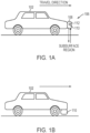
- the present disclosure generally relates to providing route planning to a vehicle (or vehicle driver) based on the type of vehicle and the terrain conditions between the originating location and destination.
- the term "terrain” includes both surface and below-ground features.
- the invention employs a terrain monitoring system including an SPR system attached to the vehicle for obtaining SPR signals as the vehicle travels along a route; the obtained SPR signals are used for navigation against reference images associated with the route.
- a navigation server bases route selection in part on the terrain associated with various routes and characteristics of the vehicle.
- a risk score is assigned to the subject vehicle. Risk scores are also associated with roadways (or roadway segments) stored in a route database, with values based on the associated terrain conditions.
- a terrain map may then be combined with the location map (or, in some embodiments, an existing map obtained from another source, such as GOOGLE MAPS) to include the locational information, terrain conditions and risk scores for various types of vehicles on each portion of the mapped routes. Terrain maps may also be fused with HD (high definition) maps used for autonomous vehicle navigation (in addition to consumer navigation maps such as those provided by GOOGLE MAPS).
- an optimal route for traveling from a specific origin location to a destination for the subject vehicle can be identified. For example, the route from the origin to the destination that has a minimal total risk score for the specific type of vehicle may be determined to be the optimal route for the subject vehicle.
- the risk score can be considered against competing factors such as trip distance and tolls based on previously provided user preferences.
- other scores e.g., energy-expenditure scores, probability-of-success scores, damage scores, wear scores, and/or loss-to-a-vehicle-subsystem scores
- path planning may employ a conventional algorithm such as A-star (A*) or D-star (D*), once the scores or costs are calculated, to then determine the optimal path.
- a navigation server comprises a route database comprising a digital map of locations and route segments connecting the locations, the route segments corresponding to roadways; a terrain database comprising terrain information associated with at least some of the route segments stored in the route database; a risk database relating a plurality of vehicle types to risk levels associated with a plurality of types of terrain; a processor; a network interface for receiving a route request over a network, the route request comprising a starting location, a destination, and a vehicle type; and a mapping module, executable by the processor, for retrieving data from the route database, the terrain database, and the risk database.
- the processor Based on the retrieved data and the received route request, the processor identifies a risk-adjusted sequence of route segments from the starting location to the destination; the risk-adjusted route accounts for a terrain risk associated with the vehicle type.
- the processor is configured to cause the risk-adjusted route to be transmitted to a source of the route request via the network interface.
- the risk database is organized to relate a plurality of vehicle types to associated terrain-related risk scores.
- the risk database may also be organized to relate the plurality of vehicle types to one or more of energy-expenditure scores, probability-of-success scores, damage scores, wear scores, or loss-to-a vehicle-subsystem scores associated with the vehicles.
- the assessment score assigned to each of the routes may have a plurality of values based on vehicle type, the optimal route also being based on a vehicle type.
- the method comprises maintaining, at a navigation server, (i) a route database comprising a digital map of locations and route segments connecting the locations, the route segments corresponding to roadways, (ii) a terrain database comprising terrain information associated with at least some of the route segments stored in the route database, and (iii) a risk database relating a plurality of vehicle types to risk levels associated with a plurality of types of terrain; receiving, by the navigation server via a network interface, a route request from the traveling vehicle, the route request comprising a starting location, a destination, and a vehicle type; at the navigation server, retrieving data from the route database, the terrain database, and the risk database and computing, based on the retrieved data and the received route request, a risk-adjusted sequence of route segments from the starting location to the destination, the risk-adjusted route accounting for a terrain risk associated with the vehicle type; and causing the risk-adjuste
- the SPR images may include surface data, i.e., data for the interface of the subsurface region with air or the local environment.
- surface data i.e., data for the interface of the subsurface region with air or the local environment.
- Suitable GPR antenna configurations and systems for processing GPR signals are described, for example, in U.S. Patent No. 8,949,024 .
- the SPR images are compared to SPR reference images that were previously acquired and stored for subsurface regions that at least partially overlap the subsurface regions for the defined route.
- the image comparison may be a registration process based on, for example, correlation; see, e.g., U.S. Patent No. 8,786,485 .
- the location of the vehicle 102 and/or the terrain conditions of the route 104 can then be determined based on the comparison.
- the detected GPR signals are combined with other real-time information, such as the weather conditions, electro-optical (EO) imagery, vehicle health monitoring using one or more sensors employed in the vehicle 102, and any suitable inputs, to estimate the terrain conditions of the route 104.
- EO electro-optical
- the vehicle 102 may be used to create terrain maps for specific route segments that will be used in navigation as described below.
- the estimated terrain conditions may advantageously provide real-world terrain modeling as well as reduced computational expenses and/or complexity for modeling the terrain/vehicle interaction in real-time.
- a risk score is assigned to the route 104 or to various types of vehicles that might be driven on the route 104.
- the risk score is adjusted for the type of vehicle. For example, if the route 104 includes rough rocks, a high risk score (e.g., 7) may be assigned to a two-wheel steering vehicle, while a low risk score (e.g., 3) may be assigned to a four-wheel steering vehicle.
- the risk scores, the terrain conditions and, if utilized, associated vehicle types may be stored along with the route 104 (or portion thereof) in a database.
- a terrain map of the routes including their associated terrain conditions and risk scores may be created.
- the terrain map may include the collected terrain conditions of the routes only; the risk score associated with the specific vehicle may be assigned in real-time during route planning.
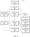
- FIG. 2 depicts an exemplary terrain monitoring system (e.g., the SPR system 108) implemented in a vehicle 102 for establishing terrain-sensitive routes or navigating travel based on SPR images.
- the SPR system 108 may include a user interface 202 through which a user can enter data to define the route or select a predefined route.
- SPR images are retrieved from an SPR reference image source 204 according to the route.
- the SPR reference image source 204 may be a local mass-storage device such as a Flash drive or hard disk; alternatively or in addition, the SPR reference image source 204 may be cloud-based (i.e., supported and maintained on a web server) and accessed remotely based on a current location determined by GPS.
- a local data store may contain SPR reference images corresponding to the vicinity of the vehicle's current location, with periodic updates being retrieved to refresh the data as the vehicle travels.
- the SPR system 108 also includes a mobile SPR system ("Mobile System") 206 having an SPR antenna array 110.
- the transmit operation of the mobile SPR system 206 is controlled by a controller (e.g., a processor) 208 that also receives the return SPR signals detected by the SPR antenna array 110.
- the controller 208 generates SPR images of the subsurface region below the road surface and/or the road surface underneath the SPR antenna array 110.
- the SPR image includes features representative of structure and objects within the subsurface region and/or on the road surface, such as rocks, roots, boulders, pipes, voids and soil layering, and other features indicative of variations in the soil or material properties in the subsurface/surface region.
- a registration module 210 compares the SPR images provided by the controller 208 to the SPR images retrieved from the SPR reference image source 204 to locate the vehicle 102 (e.g., by determining the offset of the vehicle with respect to the closest point on the route).
- the locational information e.g., offset data, or positional error data
- the conversion module 212 may generate GPS data corrected for the vehicle positional deviation from the route.
- the conversion module 212 may retrieve an existing map from a map source 214 (e.g., other navigation systems, such as GPS, or a mapping service), and then localize the obtained locational information to the existing map.
- a map source 214 e.g., other navigation systems, such as GPS, or a mapping service
- the location map of the predefined route is stored in a database 216 in system memory and/or a storage device accessible to the controller 208.
- the location data for the vehicle 104 may be used in combination with the data provided by an existing map (e.g., a map provided by GOOGLE MAPS) and/or one or more other sensors or navigation systems, such as an inertial navigation system (INS), a GPS system, a sound navigation and ranging (SONAR) system, a LIDAR system, a camera, an inertial measurement unit (IMU) and an auxiliary radar system, one or more vehicular dead-reckoning sensors (based on, e.g., steering angle and wheel odometry), and/or suspension sensors to guide the vehicle 102.
- the controller 112 may localize the obtained SPR information to an existing map generated using GPS. Approaches for utilizing the SPR system for vehicle navigation and localization are described in, for example, the '024 patent mentioned above.
- the SPR reference images also include terrain conditions associated therewith.
- the terrain conditions associated with the SPR reference images acquired from the predefined route may be determined.
- the detected GPR signals/SPR images are combined with other real-time information, such as the weather conditions, EO imagery, vehicle health monitoring using one or more sensors employed in the vehicle 102, and any suitable inputs, to determine the terrain conditions of the route 104.
- route-based terrain conditions may be stored as a map, once again locally (in the map source 214), remotely (in a cloud server), or some combination (with a locally stored terrain map updated via wireless communication with the cloud server as the vehicle travels).
- Terrain conditions and risk scores of various types of vehicles may be stored with the terrain map (in the map source 214) or in the database 216 as data associated with the various route components of maps in the map source 214.
- a terrain-optimized route for traveling from a specific origin to a destination for the specific vehicle in which the system 108 is deployed can be identified using the database 216.
- the route from the originating location to the destination that has a minimal total risk score for the currently driven vehicle may be determined to be the optimal route for this type of vehicle.
- the velocity, acceleration, orientation, angular velocity and/or angular acceleration of the vehicle 102 may be determined and continuously controlled based on the navigation map, so as to maintain the vehicle 102 to travel along the determined optimal route.
- acceleration as used herein includes linear and angular acceleration as well as higher-order derivatives such as jerk and jounce.
- terrain optimization represents an additional basis for route planning by an on-board navigation or mapping system, with vehicle-specific data being supplied remotely from a cloud server. That is, the subject vehicle does not itself include an SPR system, but the driver may obtain a terrain-optimized route from the vehicle's navigation system or an external service such as GOOGLE MAPS based on the type of vehicle and associated risk scores.
- a route-planning system may determine an optimal route that, for example, minimizes travel time but never exceeds a maximum tolerable risk score.
- the user defines or selects, via the user interface 202, other routes for the vehicle to travel.
- the terrain monitoring system may, again, continuously acquire the SPR images, and based thereon determine the locational information and terrain conditions associated with each route, and assign risk scores to various types of vehicles on the routes.
- the locational information, terrain conditions and risk scores of the vehicles may be stored along with the respective route in the location map and terrain map as described above.
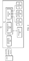
- the route database 330 contains a digital map of locations and route segments connecting the locations; in general, the route segments correspond to roadways, i.e., vehicular thoroughfares. These may be represented by geospatial coordinates or by SPR images depending on the form of navigation desired. In the former case, routes are plotted in the manner of conventional map servers, such as GOOGLE MAPS. In the latter case, the route is defined by SPR images that are transmitted to the vehicle, which is equipped with an SPR system as described above to obtain SPR images during travel and compare these with the navigation images received from the navigation server 300.
- the processor 320 executes one or more computer programs (conceptually illustrated as program modules) stored in the system memory 325.
- An operating system (such as, e.g., MICROSOFT WINDOWS, UNIX, LINUX, iOS, or ANDROID) provides low-level system functions, such as file management, resource allocation, and routing of messages from and to hardware devices and one or more higher-level applications including web server code 350 and a mapping module 355.
- the web server code 350 is conventional and facilitates web-based communication with the user via the network interface 310, receiving user-entered data and serving web pages containing maps and navigation information.
- the mapping module processes user requests by retrieving mapping data from the route database 330, terrain data from the terrain database 335, and risk-related data from the risk database 340 and computing, based on the retrieved data and the received route request, a risk-adjusted sequence of route segments from the starting location to the destination.
- the risk-adjusted route accounts for a terrain risk associated with the vehicle type.
- the mapping module 355 may first obtain a series of candidate routes from the route database; each route is associated with a score based on, e.g., estimated travel time. This functionality is well-known and conventional.
- the mapping module 355 may also obtain terrain information from the terrain database 335 and, based thereon, associated vehicle-specific risk data from the risk database 340. Based on this additional risk data, the candidate route scores may be adjusted and the routes ranked according to the adjusted scores.
- the navigation server 300 may combine route and terrain maps into a navigation map that reflects vehicle type and location, terrain conditions and the risk scores associated with the vehicle for each portion of various candidate routes. Based thereon, a terrain-optimized route may be computed for and delivered to the vehicle (via the web server code 350 and the network interface 310). Alternatively, a ranked series of candidate routes may be presented to the user, who may select a desired route. Based on the selection, geospatial or SPR route information from the route database 330 may be transmitted to the vehicle as it travels.
- the optimal route may correspond to a minimal total risk score and/or a minimal instantaneous risk score for the specific type of vehicle to travel thereon.
- the identified optimal route is provided to a vehicle's navigation system for guiding the driver along the route.
- the optimal route is provided to a vehicle control module 220 coupled to the controller 208 for autonomously operating the vehicle based thereon.
- the vehicle control module 220 may include or cooperate with electrical, mechanical and pneumatic devices in the vehicle to control steering, orientation, velocity, pose and acceleration/deceleration of the vehicle.
- the controller 208 implemented in the vehicle and the mapping module 355 implemented in the navigation server 300 may include one or more modules implemented in hardware, software, or a combination of both.
- the functions are provided as one or more software programs
- the programs may be written in any of a number of high level languages such as PYTHON, FORTRAN, PASCAL, JAVA, C, C++, C#, BASIC, various scripting languages, and/or HTML.
- the software can be implemented in an assembly language directed to the microprocessor resident on a target computer; for example, the software may be implemented in Intel 80x86 assembly language if it is configured to run on an IBM PC or PC clone.
- the software may be embodied on an article of manufacture including, but not limited to, a floppy disk, a jump drive, a hard disk, an optical disk, a magnetic tape, a PROM, an EPROM, EEPROM, field-programmable gate array, or CD-ROM.
- Embodiments using hardware circuitry may be implemented using, for example, one or more FPGA, CPLD or ASIC processors.
Landscapes
- Engineering & Computer Science (AREA)
- Remote Sensing (AREA)
- Radar, Positioning & Navigation (AREA)
- Physics & Mathematics (AREA)
- General Physics & Mathematics (AREA)
- Automation & Control Theory (AREA)
- Computer Networks & Wireless Communication (AREA)
- Electromagnetism (AREA)
- Transportation (AREA)
- Mechanical Engineering (AREA)
- Mathematical Physics (AREA)
- Navigation (AREA)
- Traffic Control Systems (AREA)
Claims (13)
- Navigationsserver (300) zum Navigieren eines Fahrzeugs (102) unter Verwendung von oberflächendurchdringendem Radar, SPR, wobei der Navigationsserver umfasst:einen Prozessor (320);eine Routendatenbank (330), in der Routendaten gespeichert sind, die SPR-Bilder einschließen, welche eine digitale Karte von Orten und Routensegmenten darstellen, die Fahrbahnen entsprechen;eine Geländedatenbank (335), in der Geländeinformationen gespeichert sind, welche aus den SPR-Bildern extrahiert wurden, die mit den in der Routendatenbank (330) gespeicherten Routensegmenten verknüpft sind;eine Risikodatenbank (340), die eine Vielzahl von Fahrzeugtypen mit Risikostufen, welche mit einer Vielzahl von Geländearten verknüpft sind, in Beziehung setzt;eine Netzwerkschnittstelle (310) zum Empfangen einer Routenanfrage über ein Netzwerk, wobei die Routenanfrage einen Startort, ein Ziel und einen Fahrzeugtyp umfasst; undein Kartenmodul (355), das durch den Prozessor (320) ausführbar und dafür konfiguriert ist, die Routenanfrage zu verarbeiten durch:Erlangen einer Vielzahl von Routenkandidaten aus der Routendatenbank (330), wobei jeder der Routenkandidaten mit einer Punktzahl verknüpft ist;Erlangen von Geländeinformationen aus der Geländedatenbank (335) für jeden der Vielzahl von Routenkandidaten;Erlangen fahrzeugspezifischer Risikodaten aus der Risikodatenbank (340) auf der Grundlage der Geländeinformationen;Anpassen der Punktzahl für jeden der Vielzahl von Routenkandidaten auf der Grundlage der fahrzeugspezifischen Risikodaten; undEinstufen der Vielzahl von Routenkandidaten gemäß den angepassten Punktzahlen;wobei der Prozessor (320) dafür konfiguriert ist:die eingestufte Vielzahl von Routenkandidaten zu der Quelle der Routenanfrage zur Präsentation für einen Benutzer zu übertragen; undauf der Grundlage einer Benutzerauswahl eines Routenkandidaten SPR-Bilder von der Routendatenbank (330) zu einem Fahrzeug (102) zu übertragen, wobei die übertragenen SPR-Bilder den ausgewählten Routenkandidaten definieren.
- Navigationsserver nach Anspruch 1, wobei die Risikodatenbank (340) dafür organisiert ist, eine Vielzahl von Fahrzeugtypen mit verknüpften geländeabhängigen Risikopunktzahlen in Beziehung zu setzen.
- Navigationsserver nach Anspruch 1, wobei die Risikodatenbank (340) dafür organisiert ist, die Vielzahl von Fahrzeugtypen mit einer oder mehreren von folgenden mit den Fahrzeugen verknüpften Punktzahlen in Beziehung zu setzen: Energieverbrauchspunktzahlen, Erfolgswahrscheinlichkeitspunktzahlen, Schadenspunktzahlen, Verschleißpunktzahlen oder Punktzahlen für Verluste an einem Fahrzeugsubsystem.
- Navigationsserver nach Anspruch 1, wobei eine jedem der Routensegmente zugewiesene Bewertungspunktzahl eine Vielzahl von Werten aufweist, die auf dem Fahrzeugtyp beruhen, wobei eine optimale Route ebenfalls auf dem Fahrzeugtyp beruht.
- Verfahren zum Bereitstellen von Navigationsdiensten für ein fahrendes Fahrzeug (102), wobei das Verfahren umfasst:in einem Navigationsserver (300) erfolgendes Pflegen von Folgendem: (i) einer Routendatenbank (330), die eine digitale Karte von Orten und Routensegmenten umfasst, die durch oberflächendurchdringende SPR-Bilder dargestellt werden, welche die Orte verbinden, wobei die Routensegmente Fahrbahnen entsprechen, (ii) einer Geländedatenbank (335), die Geländeinformationen umfasst, welche aus den SPR-Bildern extrahiert wurden, die mit den in der Routendatenbank gespeicherten Routensegmenten verknüpft sind, und (iii) einer Risikodatenbank (340), die eine Vielzahl von Fahrzeugtypen mit Risikostufen, welche mit einer Vielzahl von Geländearten verknüpft sind, in Beziehung setzt;Empfangen einer Routenanfrage vom fahrenden Fahrzeug (102) durch den Navigationsserver (300) über eine Netzwerkschnittstelle (310), wobei die Routenanfrage einen Startort, ein Ziel und einen Fahrzeugtyp umfasst;Erlangen einer Vielzahl von Routenkandidaten aus der Routendatenbank (330) durch den Navigationsserver (300), wobei jeder der Routenkandidaten mit einer Punktzahl verknüpft ist;Erlangen von Geländeinformationen für jeden der Vielzahl von Routenkandidaten durch den Navigationsserver (300) aus der Geländedatenbank (335);Erlangen von fahrzeugspezifischen Risikodaten durch den Navigationsserver (300) aus der Risikodatenbank (340) auf der Grundlage der Geländeinformationen;Anpassen der Punktzahl für jeden der Vielzahl von Routenkandidaten durch den Navigationsserver (300) auf der Grundlage der fahrzeugspezifischen Risikodaten;Einstufen der Vielzahl von Routenkandidaten durch den Navigationsserver (300) gemäß den angepassten Punktzahlen;Übertragen der eingestuften Vielzahl von Routenkandidaten durch den Navigationsserver (300) zu der Quelle der Routenanfrage zur Präsentation für einen Benutzer; undauf der Grundlage einer Benutzerauswahl eines Routenkandidaten, Übertragen von SPR-Bildern von der Routendatenbank (330) zu einem Fahrzeug (102), wobei die übertragenen SPR-Bilder den ausgewählten Routenkandidaten definieren.
- Verfahren nach Anspruch 5, wobei die Risikodatenbank (340) dafür organisiert ist, eine Vielzahl von Fahrzeugtypen mit verknüpften geländeabhängigen Risikopunktzahlen in Beziehung zu setzen.
- Verfahren nach Anspruch 5 oder 6, wobei die Risikodatenbank (340) dafür organisiert ist, die Vielzahl von Fahrzeugtypen mit einer oder mehreren von folgenden mit den Fahrzeugen verknüpften Punktzahlen in Beziehung zu setzen: Energieverbrauchspunktzahlen, Erfolgswahrscheinlichkeitspunktzahlen, Schadenspunktzahlen, Verschleißpunktzahlen oder Punktzahlen für Verluste an einem Fahrzeugsubsystem.
- Verfahren nach einem der Ansprüche 5 bis 7, wobei eine jedem der Routensegmente zugewiesene Bewertungspunktzahl eine Vielzahl von Werten aufweist, die auf dem Fahrzeugtyp beruhen, wobei eine optimale Route ebenfalls auf dem Fahrzeugtyp beruht.
- Verfahren nach Anspruch 5, ferner umfassend:drahtloses Übertragen der Routenanfrage durch das Fahrzeug (102) zum Navigationsserver (300);Empfangen einer Folge von SPR-Bildern, die einer risikoangepassten Folge von Routensegmenten vom Startort zum Ziel entsprechen, durch das Fahrzeug (102) vom Navigationsserver (300), wobei die risikoangepasste Route ein Geländerisiko berücksichtigt, das mit einem Fahrzeugtyp verknüpft ist;Erfassen von SPR-Bildern mit einem SPR-System (108), während das Fahrzeug (102) fährt; undFühren des Fahrzeugs (102) entlang der Folge von Routensegmenten auf der Grundlage eines rechnerischen Vergleichs der erfassten SPR-Bilder mit den empfangenen SPR-Bildern.
- Verfahren nach Anspruch 9, ferner umfassend:
rechnerisches Bestimmen von mindestens einem der folgenden mit dem Fahrzeug verknüpften Parameter: Lenkung, Ausrichtung, Geschwindigkeit, Lage, Beschleunigung oder Verzögerung, und zwar mindestens teilweise auf der Grundlage der erfassten SPR-Bilder. - Verfahren nach Anspruch 10, ferner umfassend:
Steuern des Betriebs des Fahrzeugs (102) mindestens teilweise auf der Grundlage der bestimmten Lenkung, Ausrichtung, Geschwindigkeit, Lage, Beschleunigung und/oder Verzögerung. - Verfahren nach einem der Ansprüche 9 bis 11, wobei das SPR-System (108) ein System mit bodendurchdringendem Radar (OPR) umfasst.
- Verfahren nach Anspruch 12, wobei das OPR-System eine OPR-Gruppenantenne (110) umfasst, die parallel zu einer Bodenoberfläche ausgerichtet ist.
Applications Claiming Priority (2)
| Application Number | Priority Date | Filing Date | Title |
|---|---|---|---|
| US201962874093P | 2019-07-15 | 2019-07-15 | |
| PCT/US2020/042052 WO2021011603A1 (en) | 2019-07-15 | 2020-07-15 | Terrain-sensitive route planning |
Publications (4)
| Publication Number | Publication Date |
|---|---|
| EP3983754A1 EP3983754A1 (de) | 2022-04-20 |
| EP3983754A4 EP3983754A4 (de) | 2022-11-30 |
| EP3983754B1 true EP3983754B1 (de) | 2025-04-09 |
| EP3983754C0 EP3983754C0 (de) | 2025-04-09 |
Family
ID=74211274
Family Applications (1)
| Application Number | Title | Priority Date | Filing Date |
|---|---|---|---|
| EP20840698.3A Active EP3983754B1 (de) | 2019-07-15 | 2020-07-15 | Terrainsensitive routenplanung |
Country Status (7)
| Country | Link |
|---|---|
| US (2) | US20210018323A1 (de) |
| EP (1) | EP3983754B1 (de) |
| JP (1) | JP7211605B2 (de) |
| CN (1) | CN114430801B (de) |
| ES (1) | ES3025686T3 (de) |
| PL (1) | PL3983754T3 (de) |
| WO (1) | WO2021011603A1 (de) |
Families Citing this family (9)
| Publication number | Priority date | Publication date | Assignee | Title |
|---|---|---|---|---|
| US11675371B2 (en) * | 2020-04-08 | 2023-06-13 | Pony Ai Inc. | System and method for fleet management |
| CN115698636A (zh) * | 2020-04-23 | 2023-02-03 | 动态清晰公司 | 基于地形的车辆导航与控制 |
| JP7431147B2 (ja) * | 2020-12-02 | 2024-02-14 | トヨタ自動車株式会社 | 情報処理装置、情報処理システム、情報処理方法、およびプログラム |
| US20250016537A1 (en) * | 2021-01-14 | 2025-01-09 | Lg Electronics Inc. | Method for transmitting message by v2x ue in wireless communication system and device therefor |
| US12360526B2 (en) * | 2021-05-14 | 2025-07-15 | Tusimple, Inc. | Systems and methods for operating an autonomous vehicle |
| JP7574780B2 (ja) * | 2021-10-29 | 2024-10-29 | 株式会社豊田自動織機 | 自律走行車、及び自律走行車の制御装置 |
| EP4515474A1 (de) * | 2022-04-28 | 2025-03-05 | GPR, Inc. | Transaktionsverarbeitung mit oberflächenpenetrierendem radar |
| US20240210185A1 (en) * | 2022-12-22 | 2024-06-27 | Intel Corporation | Entity allocation for navigated routes |
| GB2640522A (en) * | 2024-04-23 | 2025-10-29 | Jaguar Land Rover Ltd | Routing in an off-road area |
Citations (1)
| Publication number | Priority date | Publication date | Assignee | Title |
|---|---|---|---|---|
| US20140121964A1 (en) * | 2012-10-25 | 2014-05-01 | Massachusetts Institute Of Technology | Vehicle localization using surface penetrating radar |
Family Cites Families (26)
| Publication number | Priority date | Publication date | Assignee | Title |
|---|---|---|---|---|
| US6469664B1 (en) * | 1999-10-05 | 2002-10-22 | Honeywell International Inc. | Method, apparatus, and computer program products for alerting surface vessels to hazardous conditions |
| AT414280B (de) * | 2002-09-12 | 2006-11-15 | Siemens Ag Oesterreich | Verfahren zur identifikation eines mautpflichtigen strassenabschnittes |
| CA2545154C (en) * | 2003-10-06 | 2013-04-02 | Marshall University | Railroad surveying and monitoring system |
| US8606512B1 (en) * | 2007-05-10 | 2013-12-10 | Allstate Insurance Company | Route risk mitigation |
| JP5135308B2 (ja) * | 2009-09-09 | 2013-02-06 | クラリオン株式会社 | エネルギ消費量予測方法、エネルギ消費量予測装置および端末装置 |
| CA2781688A1 (en) * | 2009-11-24 | 2011-06-03 | Telogis, Inc. | Vehicle route selection based on energy usage |
| US8805707B2 (en) * | 2009-12-31 | 2014-08-12 | Hartford Fire Insurance Company | Systems and methods for providing a safety score associated with a user location |
| US8730085B2 (en) * | 2010-08-26 | 2014-05-20 | Lawrence Livermore National Security, Llc | Spot restoration for GPR image post-processing |
| US20120215505A1 (en) * | 2011-02-21 | 2012-08-23 | Honeywell International Inc. | Systems and methods for providing a vehicle movement path simulation over a network |
| EP2498059B1 (de) * | 2011-03-09 | 2020-04-29 | Harman Becker Automotive Systems GmbH | Navigationsrutenberechnung unter Nutzung dreidimensionaler Modelle |
| WO2013013306A1 (en) | 2011-07-27 | 2013-01-31 | Intelligent Mechatronic Systems Inc. | Selective vehicle tracking and vehicle routing |
| US8786485B2 (en) | 2011-08-30 | 2014-07-22 | Masachusetts Institute Of Technology | Mobile coherent change detection ground penetrating radar |
| US20120109508A1 (en) * | 2011-12-28 | 2012-05-03 | Ariel Inventions, Llc | Method and system for route navigation based on energy efficiency |
| US10345108B2 (en) * | 2012-05-16 | 2019-07-09 | Polaris Industries Inc. | System and method for multi-plane routing |
| CA2897966C (en) * | 2013-02-26 | 2023-10-31 | Polaris Industries Inc. | Recreational vehicle interactive telemetry, mapping, and trip planning system |
| WO2015160900A1 (en) * | 2014-04-15 | 2015-10-22 | Maris, Ltd | Assessing asynchronous authenticated data sources for use in driver risk management |
| JP5705361B1 (ja) * | 2014-09-02 | 2015-04-22 | アジア航測株式会社 | 車両被災リスク評価装置 |
| US10493936B1 (en) * | 2016-01-22 | 2019-12-03 | State Farm Mutual Automobile Insurance Company | Detecting and responding to autonomous vehicle collisions |
| US9702717B1 (en) * | 2016-02-19 | 2017-07-11 | International Business Machines Corporation | Creating route based on image analysis or reasoning |
| US20170292843A1 (en) * | 2016-04-07 | 2017-10-12 | Delphi Technologies, Inc. | Automated vehicle route planner with route difficulty scoring |
| GB2552028B (en) * | 2016-07-08 | 2020-07-08 | Jaguar Land Rover Ltd | Off-Road Route Rating System |
| US10725171B2 (en) * | 2017-01-27 | 2020-07-28 | Massachusetts Institute Of Technology | Method and system for localization of a vehicle using surface penetrating radar |
| JP2018205972A (ja) * | 2017-06-01 | 2018-12-27 | スズキ株式会社 | 路面情報収集システム |
| GB2563262B (en) * | 2017-06-08 | 2020-06-10 | Caterpillar Sarl | Improvements in the stability of work machines |
| US11079487B2 (en) * | 2017-08-22 | 2021-08-03 | Ford Global Technologies, Llc | Communication of infrastructure information to a vehicle via ground penetrating radar |
| US20200133298A1 (en) * | 2018-10-31 | 2020-04-30 | Xerox Corporation | Infrastructure evaluation and monitoring using ground penetrating radar data |
-
2020
- 2020-07-15 JP JP2022502920A patent/JP7211605B2/ja active Active
- 2020-07-15 EP EP20840698.3A patent/EP3983754B1/de active Active
- 2020-07-15 PL PL20840698.3T patent/PL3983754T3/pl unknown
- 2020-07-15 WO PCT/US2020/042052 patent/WO2021011603A1/en not_active Ceased
- 2020-07-15 US US16/929,437 patent/US20210018323A1/en not_active Abandoned
- 2020-07-15 ES ES20840698T patent/ES3025686T3/es active Active
- 2020-07-15 CN CN202080064748.1A patent/CN114430801B/zh active Active
-
2022
- 2022-11-03 US US17/979,915 patent/US20230236026A1/en active Pending
Patent Citations (1)
| Publication number | Priority date | Publication date | Assignee | Title |
|---|---|---|---|---|
| US20140121964A1 (en) * | 2012-10-25 | 2014-05-01 | Massachusetts Institute Of Technology | Vehicle localization using surface penetrating radar |
Also Published As
| Publication number | Publication date |
|---|---|
| JP7211605B2 (ja) | 2023-01-24 |
| WO2021011603A1 (en) | 2021-01-21 |
| PL3983754T3 (pl) | 2025-09-22 |
| CN114430801B (zh) | 2024-10-29 |
| ES3025686T3 (en) | 2025-06-09 |
| JP2022540694A (ja) | 2022-09-16 |
| EP3983754A4 (de) | 2022-11-30 |
| US20230236026A1 (en) | 2023-07-27 |
| US20210018323A1 (en) | 2021-01-21 |
| CN114430801A (zh) | 2022-05-03 |
| EP3983754C0 (de) | 2025-04-09 |
| EP3983754A1 (de) | 2022-04-20 |
Similar Documents
| Publication | Publication Date | Title |
|---|---|---|
| EP3983754B1 (de) | Terrainsensitive routenplanung | |
| US10471955B2 (en) | Stop sign and traffic light alert | |
| US11480973B2 (en) | Robotic mower boundary detection system | |
| CN106996793B (zh) | 地图更新判定系统 | |
| US10006779B2 (en) | Transmission necessity determination apparatus and route planning system | |
| US9409644B2 (en) | Automotive drone deployment system | |
| US10037037B1 (en) | Systems and methods for trajectory planning in an autonomous vehicle using different fixed durations for steering and speed parameters | |
| US11543259B2 (en) | Determining landmark detectability | |
| US10386840B2 (en) | Cruise control system and method | |
| EP3698227B1 (de) | Wegplanung für unbemanntes fahrzeug | |
| JP2019532292A (ja) | 車両位置特定の自律走行車両 | |
| US12379226B2 (en) | Generating scouting objectives | |
| US11499833B2 (en) | Inferring lane boundaries via high speed vehicle telemetry | |
| US11703347B2 (en) | Method for producing an autonomous navigation map for a vehicle | |
| US11932245B2 (en) | Systems and methods for improving path selection for automated driving | |
| US11970185B2 (en) | Data structure for storing information relating to an environment of an autonomous vehicle and methods of use thereof | |
| US20220242440A1 (en) | Methods and system for generating a lane-level map for an area of interest for navigation of an autonomous vehicle | |
| JP2020042007A (ja) | 地図上のランドマークを使用して車両の長手方向位置を補正するためのシステム及び方法 | |
| EP3605498B1 (de) | Ausgabevorrichtung, steuerungsverfahren, programm und speichermedium | |
| WO2020113038A1 (en) | Tuning autonomous vehicle dispatch using autonomous vehicle performance | |
| US11619511B2 (en) | System and method for local storage based mapping | |
| US20230055023A1 (en) | Electronic control device and vehicle control system | |
| US20210026373A1 (en) | Vehicle platooning using surface-penetrating radar systems | |
| US20220205792A1 (en) | Method and device for creating a first map | |
| WO2023141483A1 (en) | Determining perceptual spatial relevancy of objects and road actors for automated driving |
Legal Events
| Date | Code | Title | Description |
|---|---|---|---|
| STAA | Information on the status of an ep patent application or granted ep patent |
Free format text: STATUS: THE INTERNATIONAL PUBLICATION HAS BEEN MADE |
|
| PUAI | Public reference made under article 153(3) epc to a published international application that has entered the european phase |
Free format text: ORIGINAL CODE: 0009012 |
|
| STAA | Information on the status of an ep patent application or granted ep patent |
Free format text: STATUS: REQUEST FOR EXAMINATION WAS MADE |
|
| 17P | Request for examination filed |
Effective date: 20220113 |
|
| AK | Designated contracting states |
Kind code of ref document: A1 Designated state(s): AL AT BE BG CH CY CZ DE DK EE ES FI FR GB GR HR HU IE IS IT LI LT LU LV MC MK MT NL NO PL PT RO RS SE SI SK SM TR |
|
| RIC1 | Information provided on ipc code assigned before grant |
Ipc: B60W 40/06 20120101ALN20220726BHEP Ipc: G01S 13/88 20060101ALI20220726BHEP Ipc: G01C 21/20 20060101ALI20220726BHEP Ipc: G01C 21/30 20060101ALI20220726BHEP Ipc: G01C 21/00 20060101ALI20220726BHEP Ipc: G01C 21/34 20060101AFI20220726BHEP |
|
| DAV | Request for validation of the european patent (deleted) | ||
| DAX | Request for extension of the european patent (deleted) | ||
| REG | Reference to a national code |
Ref country code: DE Ipc: G01C0021340000 Ref legal event code: R079 Ref document number: 602020049245 Country of ref document: DE Free format text: PREVIOUS MAIN CLASS: G01C0021280000 |
|
| A4 | Supplementary search report drawn up and despatched |
Effective date: 20221102 |
|
| RIC1 | Information provided on ipc code assigned before grant |
Ipc: B60W 40/06 20120101ALN20221026BHEP Ipc: G01S 13/88 20060101ALI20221026BHEP Ipc: G01C 21/20 20060101ALI20221026BHEP Ipc: G01C 21/30 20060101ALI20221026BHEP Ipc: G01C 21/00 20060101ALI20221026BHEP Ipc: G01C 21/34 20060101AFI20221026BHEP |
|
| P01 | Opt-out of the competence of the unified patent court (upc) registered |
Effective date: 20230517 |
|
| STAA | Information on the status of an ep patent application or granted ep patent |
Free format text: STATUS: EXAMINATION IS IN PROGRESS |
|
| 17Q | First examination report despatched |
Effective date: 20240322 |
|
| GRAP | Despatch of communication of intention to grant a patent |
Free format text: ORIGINAL CODE: EPIDOSNIGR1 |
|
| STAA | Information on the status of an ep patent application or granted ep patent |
Free format text: STATUS: GRANT OF PATENT IS INTENDED |
|
| RIC1 | Information provided on ipc code assigned before grant |
Ipc: G01S 13/931 20200101ALN20240927BHEP Ipc: B60W 40/06 20120101ALN20240927BHEP Ipc: G01S 13/60 20060101ALI20240927BHEP Ipc: G01S 13/88 20060101ALI20240927BHEP Ipc: G01C 21/20 20060101ALI20240927BHEP Ipc: G01C 21/30 20060101ALI20240927BHEP Ipc: G01C 21/00 20060101ALI20240927BHEP Ipc: G01C 21/34 20060101AFI20240927BHEP |
|
| RIC1 | Information provided on ipc code assigned before grant |
Ipc: G01S 13/931 20200101ALN20241009BHEP Ipc: B60W 40/06 20120101ALN20241009BHEP Ipc: G01S 13/60 20060101ALI20241009BHEP Ipc: G01S 13/88 20060101ALI20241009BHEP Ipc: G01C 21/20 20060101ALI20241009BHEP Ipc: G01C 21/30 20060101ALI20241009BHEP Ipc: G01C 21/00 20060101ALI20241009BHEP Ipc: G01C 21/34 20060101AFI20241009BHEP |
|
| INTG | Intention to grant announced |
Effective date: 20241030 |
|
| GRAS | Grant fee paid |
Free format text: ORIGINAL CODE: EPIDOSNIGR3 |
|
| GRAA | (expected) grant |
Free format text: ORIGINAL CODE: 0009210 |
|
| STAA | Information on the status of an ep patent application or granted ep patent |
Free format text: STATUS: THE PATENT HAS BEEN GRANTED |
|
| RAP3 | Party data changed (applicant data changed or rights of an application transferred) |
Owner name: GPR, INC. |
|
| AK | Designated contracting states |
Kind code of ref document: B1 Designated state(s): AL AT BE BG CH CY CZ DE DK EE ES FI FR GB GR HR HU IE IS IT LI LT LU LV MC MK MT NL NO PL PT RO RS SE SI SK SM TR |
|
| REG | Reference to a national code |
Ref country code: GB Ref legal event code: FG4D |
|
| REG | Reference to a national code |
Ref country code: CH Ref legal event code: EP |
|
| REG | Reference to a national code |
Ref country code: DE Ref legal event code: R096 Ref document number: 602020049245 Country of ref document: DE |
|
| REG | Reference to a national code |
Ref country code: IE Ref legal event code: FG4D |
|
| REG | Reference to a national code |
Ref country code: ES Ref legal event code: FG2A Ref document number: 3025686 Country of ref document: ES Kind code of ref document: T3 Effective date: 20250609 |
|
| P04 | Withdrawal of opt-out of the competence of the unified patent court (upc) registered |
Free format text: CASE NUMBER: APP_22422/2025 Effective date: 20250513 |
|
| U01 | Request for unitary effect filed |
Effective date: 20250508 |
|
| U07 | Unitary effect registered |
Designated state(s): AT BE BG DE DK EE FI FR IT LT LU LV MT NL PT RO SE SI Effective date: 20250515 |
|
| U20 | Renewal fee for the european patent with unitary effect paid |
Year of fee payment: 6 Effective date: 20250728 |
|
| PG25 | Lapsed in a contracting state [announced via postgrant information from national office to epo] |
Ref country code: GR Free format text: LAPSE BECAUSE OF FAILURE TO SUBMIT A TRANSLATION OF THE DESCRIPTION OR TO PAY THE FEE WITHIN THE PRESCRIBED TIME-LIMIT Effective date: 20250710 |
|
| PGFP | Annual fee paid to national office [announced via postgrant information from national office to epo] |
Ref country code: GB Payment date: 20250722 Year of fee payment: 6 |
|
| PG25 | Lapsed in a contracting state [announced via postgrant information from national office to epo] |
Ref country code: HR Free format text: LAPSE BECAUSE OF FAILURE TO SUBMIT A TRANSLATION OF THE DESCRIPTION OR TO PAY THE FEE WITHIN THE PRESCRIBED TIME-LIMIT Effective date: 20250409 |
|
| PG25 | Lapsed in a contracting state [announced via postgrant information from national office to epo] |
Ref country code: RS Free format text: LAPSE BECAUSE OF FAILURE TO SUBMIT A TRANSLATION OF THE DESCRIPTION OR TO PAY THE FEE WITHIN THE PRESCRIBED TIME-LIMIT Effective date: 20250709 |
|
| PG25 | Lapsed in a contracting state [announced via postgrant information from national office to epo] |
Ref country code: IS Free format text: LAPSE BECAUSE OF FAILURE TO SUBMIT A TRANSLATION OF THE DESCRIPTION OR TO PAY THE FEE WITHIN THE PRESCRIBED TIME-LIMIT Effective date: 20250809 |