EP3983192B1 - Verfahren zur herstellung eines spritzgegossenen gegenstandes, insbesondere eines flaschenvorformlings - Google Patents
Verfahren zur herstellung eines spritzgegossenen gegenstandes, insbesondere eines flaschenvorformlings Download PDFInfo
- Publication number
- EP3983192B1 EP3983192B1 EP20732199.3A EP20732199A EP3983192B1 EP 3983192 B1 EP3983192 B1 EP 3983192B1 EP 20732199 A EP20732199 A EP 20732199A EP 3983192 B1 EP3983192 B1 EP 3983192B1
- Authority
- EP
- European Patent Office
- Prior art keywords
- bottle
- preform
- zone
- injection
- neck
- Prior art date
- Legal status (The legal status is an assumption and is not a legal conclusion. Google has not performed a legal analysis and makes no representation as to the accuracy of the status listed.)
- Active
Links
Images


Classifications
-
- B—PERFORMING OPERATIONS; TRANSPORTING
- B29—WORKING OF PLASTICS; WORKING OF SUBSTANCES IN A PLASTIC STATE IN GENERAL
- B29B—PREPARATION OR PRETREATMENT OF THE MATERIAL TO BE SHAPED; MAKING GRANULES OR PREFORMS; RECOVERY OF PLASTICS OR OTHER CONSTITUENTS OF WASTE MATERIAL CONTAINING PLASTICS
- B29B11/00—Making preforms
- B29B11/06—Making preforms by moulding the material
- B29B11/08—Injection moulding
-
- B—PERFORMING OPERATIONS; TRANSPORTING
- B29—WORKING OF PLASTICS; WORKING OF SUBSTANCES IN A PLASTIC STATE IN GENERAL
- B29B—PREPARATION OR PRETREATMENT OF THE MATERIAL TO BE SHAPED; MAKING GRANULES OR PREFORMS; RECOVERY OF PLASTICS OR OTHER CONSTITUENTS OF WASTE MATERIAL CONTAINING PLASTICS
- B29B11/00—Making preforms
- B29B11/14—Making preforms characterised by structure or composition
-
- B—PERFORMING OPERATIONS; TRANSPORTING
- B29—WORKING OF PLASTICS; WORKING OF SUBSTANCES IN A PLASTIC STATE IN GENERAL
- B29C—SHAPING OR JOINING OF PLASTICS; SHAPING OF MATERIAL IN A PLASTIC STATE, NOT OTHERWISE PROVIDED FOR; AFTER-TREATMENT OF THE SHAPED PRODUCTS, e.g. REPAIRING
- B29C45/00—Injection moulding, i.e. forcing the required volume of moulding material through a nozzle into a closed mould; Apparatus therefor
- B29C45/0001—Injection moulding, i.e. forcing the required volume of moulding material through a nozzle into a closed mould; Apparatus therefor characterised by the choice of material
-
- B—PERFORMING OPERATIONS; TRANSPORTING
- B29—WORKING OF PLASTICS; WORKING OF SUBSTANCES IN A PLASTIC STATE IN GENERAL
- B29C—SHAPING OR JOINING OF PLASTICS; SHAPING OF MATERIAL IN A PLASTIC STATE, NOT OTHERWISE PROVIDED FOR; AFTER-TREATMENT OF THE SHAPED PRODUCTS, e.g. REPAIRING
- B29C45/00—Injection moulding, i.e. forcing the required volume of moulding material through a nozzle into a closed mould; Apparatus therefor
- B29C45/17—Component parts, details or accessories; Auxiliary operations
- B29C45/72—Heating or cooling
- B29C45/7207—Heating or cooling of the moulded articles
-
- B—PERFORMING OPERATIONS; TRANSPORTING
- B29—WORKING OF PLASTICS; WORKING OF SUBSTANCES IN A PLASTIC STATE IN GENERAL
- B29C—SHAPING OR JOINING OF PLASTICS; SHAPING OF MATERIAL IN A PLASTIC STATE, NOT OTHERWISE PROVIDED FOR; AFTER-TREATMENT OF THE SHAPED PRODUCTS, e.g. REPAIRING
- B29C49/00—Blow-moulding, i.e. blowing a preform or parison to a desired shape within a mould; Apparatus therefor
- B29C49/0005—Blow-moulding, i.e. blowing a preform or parison to a desired shape within a mould; Apparatus therefor characterised by the material
-
- B—PERFORMING OPERATIONS; TRANSPORTING
- B29—WORKING OF PLASTICS; WORKING OF SUBSTANCES IN A PLASTIC STATE IN GENERAL
- B29C—SHAPING OR JOINING OF PLASTICS; SHAPING OF MATERIAL IN A PLASTIC STATE, NOT OTHERWISE PROVIDED FOR; AFTER-TREATMENT OF THE SHAPED PRODUCTS, e.g. REPAIRING
- B29C49/00—Blow-moulding, i.e. blowing a preform or parison to a desired shape within a mould; Apparatus therefor
- B29C49/02—Combined blow-moulding and manufacture of the preform or the parison
- B29C49/06—Injection blow-moulding
-
- B—PERFORMING OPERATIONS; TRANSPORTING
- B29—WORKING OF PLASTICS; WORKING OF SUBSTANCES IN A PLASTIC STATE IN GENERAL
- B29C—SHAPING OR JOINING OF PLASTICS; SHAPING OF MATERIAL IN A PLASTIC STATE, NOT OTHERWISE PROVIDED FOR; AFTER-TREATMENT OF THE SHAPED PRODUCTS, e.g. REPAIRING
- B29C49/00—Blow-moulding, i.e. blowing a preform or parison to a desired shape within a mould; Apparatus therefor
- B29C49/071—Preforms or parisons characterised by their configuration, e.g. geometry, dimensions or physical properties
-
- B—PERFORMING OPERATIONS; TRANSPORTING
- B29—WORKING OF PLASTICS; WORKING OF SUBSTANCES IN A PLASTIC STATE IN GENERAL
- B29C—SHAPING OR JOINING OF PLASTICS; SHAPING OF MATERIAL IN A PLASTIC STATE, NOT OTHERWISE PROVIDED FOR; AFTER-TREATMENT OF THE SHAPED PRODUCTS, e.g. REPAIRING
- B29C49/00—Blow-moulding, i.e. blowing a preform or parison to a desired shape within a mould; Apparatus therefor
- B29C49/08—Biaxial stretching during blow-moulding
- B29C49/10—Biaxial stretching during blow-moulding using mechanical means for prestretching
- B29C49/12—Stretching rods
-
- B—PERFORMING OPERATIONS; TRANSPORTING
- B29—WORKING OF PLASTICS; WORKING OF SUBSTANCES IN A PLASTIC STATE IN GENERAL
- B29C—SHAPING OR JOINING OF PLASTICS; SHAPING OF MATERIAL IN A PLASTIC STATE, NOT OTHERWISE PROVIDED FOR; AFTER-TREATMENT OF THE SHAPED PRODUCTS, e.g. REPAIRING
- B29C49/00—Blow-moulding, i.e. blowing a preform or parison to a desired shape within a mould; Apparatus therefor
- B29C49/42—Component parts, details or accessories; Auxiliary operations
- B29C49/64—Heating or cooling preforms, parisons or blown articles
- B29C49/6409—Thermal conditioning of preforms
- B29C49/6436—Thermal conditioning of preforms characterised by temperature differential
- B29C49/6445—Thermal conditioning of preforms characterised by temperature differential through the preform length
- B29C49/6452—Thermal conditioning of preforms characterised by temperature differential through the preform length by heating the neck
-
- B—PERFORMING OPERATIONS; TRANSPORTING
- B29—WORKING OF PLASTICS; WORKING OF SUBSTANCES IN A PLASTIC STATE IN GENERAL
- B29C—SHAPING OR JOINING OF PLASTICS; SHAPING OF MATERIAL IN A PLASTIC STATE, NOT OTHERWISE PROVIDED FOR; AFTER-TREATMENT OF THE SHAPED PRODUCTS, e.g. REPAIRING
- B29C49/00—Blow-moulding, i.e. blowing a preform or parison to a desired shape within a mould; Apparatus therefor
- B29C49/42—Component parts, details or accessories; Auxiliary operations
- B29C49/64—Heating or cooling preforms, parisons or blown articles
- B29C49/6472—Heating or cooling preforms, parisons or blown articles in several stages
-
- B—PERFORMING OPERATIONS; TRANSPORTING
- B29—WORKING OF PLASTICS; WORKING OF SUBSTANCES IN A PLASTIC STATE IN GENERAL
- B29C—SHAPING OR JOINING OF PLASTICS; SHAPING OF MATERIAL IN A PLASTIC STATE, NOT OTHERWISE PROVIDED FOR; AFTER-TREATMENT OF THE SHAPED PRODUCTS, e.g. REPAIRING
- B29C45/00—Injection moulding, i.e. forcing the required volume of moulding material through a nozzle into a closed mould; Apparatus therefor
- B29C45/17—Component parts, details or accessories; Auxiliary operations
- B29C45/72—Heating or cooling
- B29C45/7207—Heating or cooling of the moulded articles
- B29C2045/7264—Cooling or heating the neck portion of preforms
-
- B—PERFORMING OPERATIONS; TRANSPORTING
- B29—WORKING OF PLASTICS; WORKING OF SUBSTANCES IN A PLASTIC STATE IN GENERAL
- B29C—SHAPING OR JOINING OF PLASTICS; SHAPING OF MATERIAL IN A PLASTIC STATE, NOT OTHERWISE PROVIDED FOR; AFTER-TREATMENT OF THE SHAPED PRODUCTS, e.g. REPAIRING
- B29C49/00—Blow-moulding, i.e. blowing a preform or parison to a desired shape within a mould; Apparatus therefor
- B29C49/02—Combined blow-moulding and manufacture of the preform or the parison
- B29C2049/023—Combined blow-moulding and manufacture of the preform or the parison using inherent heat of the preform, i.e. 1 step blow moulding
-
- B—PERFORMING OPERATIONS; TRANSPORTING
- B29—WORKING OF PLASTICS; WORKING OF SUBSTANCES IN A PLASTIC STATE IN GENERAL
- B29C—SHAPING OR JOINING OF PLASTICS; SHAPING OF MATERIAL IN A PLASTIC STATE, NOT OTHERWISE PROVIDED FOR; AFTER-TREATMENT OF THE SHAPED PRODUCTS, e.g. REPAIRING
- B29C49/00—Blow-moulding, i.e. blowing a preform or parison to a desired shape within a mould; Apparatus therefor
- B29C49/02—Combined blow-moulding and manufacture of the preform or the parison
- B29C49/06—Injection blow-moulding
- B29C2049/065—Means for compensating or avoiding the shrinking of preforms, e.g. in the injection mould or outside the injection mould
-
- B—PERFORMING OPERATIONS; TRANSPORTING
- B29—WORKING OF PLASTICS; WORKING OF SUBSTANCES IN A PLASTIC STATE IN GENERAL
- B29C—SHAPING OR JOINING OF PLASTICS; SHAPING OF MATERIAL IN A PLASTIC STATE, NOT OTHERWISE PROVIDED FOR; AFTER-TREATMENT OF THE SHAPED PRODUCTS, e.g. REPAIRING
- B29C2945/00—Indexing scheme relating to injection moulding, i.e. forcing the required volume of moulding material through a nozzle into a closed mould
- B29C2945/76—Measuring, controlling or regulating
- B29C2945/76494—Controlled parameter
- B29C2945/76625—Humidity, moisture
-
- B—PERFORMING OPERATIONS; TRANSPORTING
- B29—WORKING OF PLASTICS; WORKING OF SUBSTANCES IN A PLASTIC STATE IN GENERAL
- B29C—SHAPING OR JOINING OF PLASTICS; SHAPING OF MATERIAL IN A PLASTIC STATE, NOT OTHERWISE PROVIDED FOR; AFTER-TREATMENT OF THE SHAPED PRODUCTS, e.g. REPAIRING
- B29C2945/00—Indexing scheme relating to injection moulding, i.e. forcing the required volume of moulding material through a nozzle into a closed mould
- B29C2945/76—Measuring, controlling or regulating
- B29C2945/76822—Phase or stage of control
- B29C2945/76903—After-treatment
-
- B—PERFORMING OPERATIONS; TRANSPORTING
- B29—WORKING OF PLASTICS; WORKING OF SUBSTANCES IN A PLASTIC STATE IN GENERAL
- B29C—SHAPING OR JOINING OF PLASTICS; SHAPING OF MATERIAL IN A PLASTIC STATE, NOT OTHERWISE PROVIDED FOR; AFTER-TREATMENT OF THE SHAPED PRODUCTS, e.g. REPAIRING
- B29C2949/00—Indexing scheme relating to blow-moulding
- B29C2949/07—Preforms or parisons characterised by their configuration
- B29C2949/0715—Preforms or parisons characterised by their configuration the preform having one end closed
-
- B—PERFORMING OPERATIONS; TRANSPORTING
- B29—WORKING OF PLASTICS; WORKING OF SUBSTANCES IN A PLASTIC STATE IN GENERAL
- B29C—SHAPING OR JOINING OF PLASTICS; SHAPING OF MATERIAL IN A PLASTIC STATE, NOT OTHERWISE PROVIDED FOR; AFTER-TREATMENT OF THE SHAPED PRODUCTS, e.g. REPAIRING
- B29C2949/00—Indexing scheme relating to blow-moulding
- B29C2949/07—Preforms or parisons characterised by their configuration
- B29C2949/0861—Other specified values, e.g. values or ranges
- B29C2949/0862—Crystallinity
- B29C2949/0863—Crystallinity at the neck portion
-
- B—PERFORMING OPERATIONS; TRANSPORTING
- B29—WORKING OF PLASTICS; WORKING OF SUBSTANCES IN A PLASTIC STATE IN GENERAL
- B29K—INDEXING SCHEME ASSOCIATED WITH SUBCLASSES B29B, B29C OR B29D, RELATING TO MOULDING MATERIALS OR TO MATERIALS FOR MOULDS, REINFORCEMENTS, FILLERS OR PREFORMED PARTS, e.g. INSERTS
- B29K2995/00—Properties of moulding materials, reinforcements, fillers, preformed parts or moulds
- B29K2995/0037—Other properties
- B29K2995/004—Semi-crystalline
-
- B—PERFORMING OPERATIONS; TRANSPORTING
- B29—WORKING OF PLASTICS; WORKING OF SUBSTANCES IN A PLASTIC STATE IN GENERAL
- B29K—INDEXING SCHEME ASSOCIATED WITH SUBCLASSES B29B, B29C OR B29D, RELATING TO MOULDING MATERIALS OR TO MATERIALS FOR MOULDS, REINFORCEMENTS, FILLERS OR PREFORMED PARTS, e.g. INSERTS
- B29K2995/00—Properties of moulding materials, reinforcements, fillers, preformed parts or moulds
- B29K2995/0037—Other properties
- B29K2995/0093—Other properties hydrophobic
-
- B—PERFORMING OPERATIONS; TRANSPORTING
- B29—WORKING OF PLASTICS; WORKING OF SUBSTANCES IN A PLASTIC STATE IN GENERAL
- B29L—INDEXING SCHEME ASSOCIATED WITH SUBCLASS B29C, RELATING TO PARTICULAR ARTICLES
- B29L2031/00—Other particular articles
- B29L2031/712—Containers; Packaging elements or accessories, Packages
- B29L2031/7142—Aerosol containers
-
- B—PERFORMING OPERATIONS; TRANSPORTING
- B29—WORKING OF PLASTICS; WORKING OF SUBSTANCES IN A PLASTIC STATE IN GENERAL
- B29L—INDEXING SCHEME ASSOCIATED WITH SUBCLASS B29C, RELATING TO PARTICULAR ARTICLES
- B29L2031/00—Other particular articles
- B29L2031/712—Containers; Packaging elements or accessories, Packages
- B29L2031/7158—Bottles
Definitions
- the present invention relates to the manufacture of finished and semifinished products, in particular bottles, and more particularly aerosol bottles, that is to say pressurized bottles intended to receive a composition and a propellant gas, in particular a liquefied propellant gas.
- a preform is produced by injection-molding a thermoplastic material, for example PET, with a neck intended for the fastening of a dispensing head.
- a thermoplastic material for example PET
- the plastic material is subjected to a crystallizing heat treatment in the region of said neck.
- the preform is transferred to a blow-molding station in order to give the body of the bottle its final shape. While reinforcing the mechanical strength, crystallization makes it possible make the bottle lighter.
- a plastic aerosol bottle should comply with regulations. Tests on a plastic aerosol bottle containing a liquefied gas are generally more difficult to satisfy than those relating to plastic aerosol bottles containing a compressed gas.
- the tests make it possible to verify that the plastic pressurized bottle is able to resist an operating pressure of generally several bar on account of the presence of a pressurized gas, notably a pressurized liquefied gas, inside it.
- a pressurized gas notably a pressurized liquefied gas
- This resistance has to be verified at a relatively high temperature in order to ensure safety in use.
- the bottle can be filled under vacuum, this ensures squeeze resistance when the reduced pressure is at a maximum, before filling is started.
- the bottle also has to be resistant to impacts, notably to being dropped at different temperatures.
- US 8 171 705 provides a method for filling a multilayer bottle including outermost and innermost layers and at least one barrier layer interposed between the outermost and innermost layers, with a material to be stored therein.
- US 2018/179377 relates to polyester-ether compositions and their use in polyester resins.
- Containers made from these polyester-ether compositions give improved oxygen barrier protection for the filled fluids while maintaining good visual properties of the containers.
- KR 2018 0117936 provides a manufacturing method of a beverage container capable of enhancing the degree of crystallization of the beverage container.
- JP 2003 053826 discloses an apparatus for producing a neck part-crystallized preform.
- the apparatus comprises a preform molding apparatus for the injection-molding of the preform, a neck part crystallization apparatus for crystallizing the neck part of the preform and a first conveyance line for conveying the preform from the molding apparatus to the crystallization apparatus wherein the conveyance line comprises a humidity controller for allowing the preform to absorb moisture.
- the invention aims to remedy this problem and the subject thereof, according to a first of its aspects, is a method in accordance with claim 1. Better still the preform is held for a sufficient duration under storage conditions to undergo a moisture uptake of at least 0.8%, and even better still at least 1%, by weight, the uptake being preferably less than 3% by weight.
- Said part that is crystallized may be the neck of the preform.
- the moisture content of the plastic material is relatively low, typically around 100 ppm.
- the invention is based on the finding that such moisture uptake makes it possible to improve the thermal conductivity of the material of the article, in particular of the preform, and thus to facilitate the action of the crystallizing heat treatment, which can thus be effected under conditions that bring about a satisfactory and reproducible result.
- the presence of moisture can in particular make it easier to obtain a desired crystallinity gradient within the crystallized part, in particular the neck.
- thermoplastic material used during the injection-molding of the article, in particular of the preform is conventionally dehydrated.
- the water content of the plastic material is zero or virtually zero.
- the moisture uptake can thus be promoted by placing the article, in particular the preform, in an environment having a relatively high relative humidity.
- the relative humidity during storage is at least 60%, or even better still at least 80%.
- the relative humidity level desired can be achieved by humidifying the environment around the preform, for example by virtue of a suitable air conditioning system.
- the relative humidity is brought about by the atmospheric conditions outside the storage location, and in this case the storage duration may be variable in order to allow time to obtain the desired level of moisture uptake. In the event of dry weather, this duration could be prolonged, compared with storage during wet weather.
- the storage duration is chosen as a function of the relative humidity during storage, and may be at least 1 month, 3 months or 1 year.
- the storage temperature is preferably between 5°C and 35°C, better still between 15 and 25°C.
- the injection-molded article in particular the injection-molded preform, can be stored in a large bag during the moisture uptake, optionally provided with holes for facilitating exchanges with the ambient air.
- the crystallizable polymer material is PET, although the invention is not limited to this polymer.
- the plastic material used may include at least one polymer chosen from the group consisting of PET or PETP (polyethylene terephthalate), PEN (polyethylene naphthalate), PCT (polycyclohexylenedimethylene terephthalate), recycled polymers, in particular referred to as PCR (post-consumer recycled) polymers, in particular recycled PET, bioPET (biological polyethylene terephthalate), PP (polypropylene), PE (polyethylene), PEF (polyethylene furanoate), PET-G/PCT-G (glycolized polyethylene terephthalate/glycolized polycyclohexylenedimethylene terephthalate), PET with mineral fillers, for example calcium carbonate or glass fibers, PC (polycarbonate), POM (polyoxymethylene), SMMA (styrene methyl methacrylate), PMMA (polymethyl methacrylate),
- the crystallization step in particular of the neck, can be carried out with the aid of a heating device having at least one infrared radiation lamp or any other energy input means.
- the heating device is preferably adjusted so as to apply a temperature gradient for obtaining the desired degrees of crystallinity.
- the heating temperature may be nonuniform.
- the distance between the heating device and the preform may be adjusted to this effect.
- the heating device is preferably arranged in such a way as to prevent crystallization of the tubular body of the preform, which will be heated later and then subjected to the blowing operation.
- At least one cooling bar may be brought close to the preform from the inside or outside thereof, simultaneously with the heating. In a variant or additionally, it may be introduced into the preform simultaneously with the heating, notably via the opening in the neck of the preform.
- Such a cooling bar serves to cool the zone that is not intended to be crystallized and also to achieve a gradient between the heated zone, where the maximum degree of crystallinity is obtained, and the unheated zone, where the degree of crystallinity is at a minimum.
- Another cooling system, different than a cooling bar may be provided for the same purpose without departing from the scope of the invention.
- the bottle may contain a cosmetic or other product.
- the bottle may contain a liquefied or compressed gas, with an overpressure of between 1 and 13 bar (10 5 and 13.10 5 Pa) at 20°C.
- the bottle may also receive a pump crimped to the neck, and not be pressurized.
- the bottle may have a dispensing system for dispensing the cosmetic product contained therein, provided with an actuating member that the user can press in order to dispense the product through at least one outlet orifice, for example in the form of a spray, a foam, a gel or a cream.
- the dispensing system has for example a push button and a cup, fastened to the container, bearing a valve with a hollow control stem which is controlled by being depressed or tilted.
- the bottle may also have a system of the Bag-on-Valve (BoV) type, having an aerosol valve with a welded bag.
- the composition is placed inside the bag while the propellant fills the space around the bag inside the bottle.
- the composition is dispensed by the propellant by simply pressing the bag.
- the actuating member is depressed, the composition is extracted from the bag by the pressure of the propellant, this causing the composition to be dispensed in particular in the form of a spray, cream or gel.
- a further subject of the invention is a method for manufacturing a bottle, in particular an aerosol bottle, wherein the bottle is formed by stretch-blow-molding the preform having a crystallized neck obtained by the method as defined above.
- a further subject of the invention is the bottle, in particular aerosol bottle, obtained by the implementation of this method.
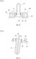
- Figure 1 shows an example of an aerosol bottle 1 produced by implementing the method according to the invention.
- This aerosol bottle 1 has a body 2 made of thermoplastic material, shown on its own in figure 3 , having a neck 3 on which there is mounted a dispensing head 5 having a push button 4 equipped with a dispensing nozzle 6 and which the user can press to cause the contents of the bottle to be dispensed.
- the dispensing head 5 has a cup bearing a valve, which can be fastened to the neck 3 by snap-fastening, crimping or any other means, and have a dip tube (not visible) extending down to the bottom of the bottle.
- the bottle contains a composition to be dispensed, for example a cosmetic composition, and a liquefied propellant gas, for example butane.
- a composition to be dispensed for example a cosmetic composition
- a liquefied propellant gas for example butane.
- the body is made from PET, but other thermoplastic materials may be suitable.
- the neck 3 is at least partially crystallized, while the rest of the body 2 is in an amorphous form.
- the amorphous nature causes the material to be transparent, while the crystallization gives it a whitish opacity.
- the crystallization of the neck 3 makes it possible to improve the mechanical characteristics thereof.
- a preform 11 as shown schematically in figure 2 , is produced by injection-molding.
- This preform 11 already has the neck 3 with its final shape, and a tubular body 14 closed at one end 16.
- the neck 3 may have a flange 22 at its base, this being useful for blow-molding, making it possible to form an end-stop that rests on the blow-molding mold and is likewise useful for conveying the preform 11 or the body 2 of the bottle, during the preheating of the preform and/or blow-molding and/or after blow-molding during the cooling phase.
- the neck 3 has in its upper part an annular bulge 24 that serves for attaching the dispensing system.
- the preform 11 undergoes a moisture uptake step 13 under conditions chosen such that this moisture uptake is at least 0.4% by weight.
- the weight of the preform after moisture uptake is greater by a factor of at least 1.04 than that of the preform before moisture uptake.
- the desired moisture uptake it is possible to store a large number of preforms 11 in a large bag in an air-conditioned store exhibiting a temperature and a humidity that are controlled such that the temperature is between 15 and 25 °C and the relative humidity is at least 30% RH, better still at least 60% RH, even better still at least 80% RH.
- the storage duration is chosen depending on the storage conditions so as to result in the desired moisture uptake. It is for example at least 7 days, better still at least 15 days.
- the preform 11 is subjected to a crystallizing heat treatment 15 of the neck 3, by exposing the neck 3 of the preform 11 to a heating means employing infrared radiation for example. Examples of heating devices that can be used to effect this heat treatment are described below.
- the crystallizing step is preferably implemented in such a way as to obtain, in the neck 3, a first zone 30 and a second zone 31, intermediate between the first zone 30 and the tubular body 14, as illustrated in figure 5 , having a degree of crystallinity lower than that of the first zone, this second zone extending axially over a height of at least 0.5 mm, and in such a way that the polymer material of the tubular body 14 remains in an amorphous state.
- the first zone 20 is located between the upper end 18 of the neck 3 and a lower end at the boundary with the upper end of the second zone 31.
- This boundary between the first zone 30 and the second zone 31 is embodied, in a virtual manner in figure 5 , by a line L 1 consisting of a boundary surface between these two zones 30 and 31.
- the second zone 31 is delimited at the top by this line L 1 and at the bottom by the line L 2 , which is a virtual line, consisting of a boundary surface between the second zone 31 and the tubular body 14. Even though it belongs to the neck 3 of the preform 11, the second zone 21 constitutes an intermediate zone between the neck 3 and the tubular body 14.
- the boundary surfaces Li and L 2 are not perpendicular to the longitudinal axis X of the preform 11 but form a conical surface exhibiting a half cone angle ⁇ equal to approximately 60° with the axis X, as can be seen.
- the two boundary surfaces have the same angle ⁇ in this example, but the situation could be otherwise without departing from the scope of the invention.
- the second zone 31 has a mass-fraction degree of crystallinity lower than that of the first zone 30, which is preferably nonuniform within the second zone 31.
- the mass-fraction degree of crystallinity of the tubular body 14 is close to zero, the polymer material being in an amorphous state in this part of the preform 11, or in a semicrystalline state if the preform is made of PP or PE.
- the first zone 30 of the neck is white in color, the tubular body 14 for its part remaining substantially transparent, whereas the, intermediate, second zone 31 of the neck 3 has a milky appearance, with beige-grey tones, with its visual appearance potentially being nonuniform.
- the light transmission percentage is higher in the zone of the tubular body 14 than in the second zone 31, which itself has a light transmission percentage that is higher than in the first zone 30, in particular at the wavelength of 973 cm -1 . This is connected with the fact that the higher the degree of crystallinity, the lower the light transmission percentage.
- the second zone 31 thus forms not only an intermediate zone between the first zone 30 and the tubular body 14 but also a transition zone in terms of degree of crystallinity because the latter is at a maximum in the first zone 30 and at a minimum in the tubular body 14.
- the presence of this transition zone makes it possible to improve the mechanical properties, in particular the mechanical strength, of the bottle.
- the bottle produced from the preform 11 may thus be able to withstand the temperature of 75°C.
- the degree of crystallinity in the second zone 31 is preferably nonuniform, varying within this zone, either linearly or nonlinearly, in the radial and/or axial direction(s).
- the degree of crystallinity in the second zone 31, in the axial direction decreases substantially linearly from the line L 1 toward the line L 2 .
- the degree of crystallinity in the second zone 21, in the radial direction decreases substantially linearly from the outer surface 27 toward the inner surface 26.
- the degree of crystallinity varies axially and radially in the second zone 31, as illustrated in figures 6 and 7 .
- the degree of crystallinity may be expressed in the form T c (x, r).
- the degree of crystallinity may exhibit symmetry of revolution, meaning that T c (x, r) is constant regardless of the azimuth ⁇ about the longitudinal axis X.
- T c (x, r) varies with the angle ⁇ .
- the transition between the first zone 30 and the second zone 31, for a given r may be considered, by definition, to extend axially between 0.9 T c max and 1.1 T c mm , where T c max denotes the highest degree of crystallinity of the first zone and T c min the least high degree of crystallinity of the tubular body.
- Each of these boundary surfaces may be substantially conical with a vertex half angle ⁇ with respect to the axis X.
- the flange 22 may be formed on the circumference of the neck 3 in the lower part of the first zone 30, in particular at the lower end of the first zone 30, which in this case may define the boundary with the second zone 31.
- the mass-fraction degree of crystallinity of the neck 3 in the first zone 30 is preferably between 20% and 80%, in particular between 25% and 50%, preferably between 25% and 40%, the mass-fraction degree of crystallinity of the neck in the first zone 30 preferably being substantially uniform axially and radially.
- the degree of crystallinity may be substantially uniform over the entire height of the first zone, which may be between 7 and 11 mm, being for example equal to 9 mm.
- the mass-fraction degree of crystallinity in the second zone 31 of the neck 3 is for example between 8% and 20%.
- the degree of crystallinity preferably exhibits, as indicated above, an axial gradient within the second zone, the degree of crystallinity preferably decreasing from a first end of the second zone in contact with the first zone toward a second end of the second zone in contact with the tubular body.
- the degree of crystallinity may vary linearly depending on the position on the longitudinal axis in the second zone, from the first end toward the second end.
- the degree of crystallinity varies nonlinearly in the axial direction.
- the degree of crystallinity may exhibit a radial gradient within the second zone, the degree of crystallinity preferably decreasing from an outer surface 27 of the preform toward an inner surface 26 of the preform.
- the degree of crystallinity may vary substantially linearly in the second zone in the radial direction between the inner surface of the preform and the outer surface of the preform.
- the degree of crystallinity varies nonlinearly in the radial direction.
- Figure 8 shows an example of a heating device 100 that can be used in the heat treatment step of the preform in order to heat the first zone 30 and partially heat the second zone 31 so as to cause at least partial crystallization of the polymer.
- the heating device 100 has a plurality of mirrors 42 that make it possible to limit the heating achieved by infrared radiation lamps 43 to the intended zones.
- the preform 11 is capped by an oven mandrel 44 that is inserted into the opening in the neck 3 and extends inside the neck 3 as far as the lower limit of the first zone 30.
- one or more mirrors have indentations so as to promote the crystallinity gradient in the second zone 31.
- FIG. 9 Another example of a heating device 100 has been illustrated in Figure 9 .
- an infrared radiation lamp 43 is disposed on the outside of the preform 11 in the zone situated around the neck 3.
- a cooling bar 47 is brought close to the preform from the outside, under the flange 22.
- a rod 46 has been inserted through the opening in the neck 3 along the longitudinal axis X and is present inside the tubular body 14. The rod 46 causes the preform to rotate on itself in such a way that the entire perimeter is heated uniformly and cooled uniformly.
- the cooling of the preform after heating may be effected using natural convection, that is to say relatively slowly, so as to finalize crystallization.
- the cooling duration is for example longer than 30 s, in particular between 30 s and 10 min.
- the cooling is therefore slow, at ambient temperature.
- the preform is transferred to a stretch-blow-molding station so as to form, in a stretch-blow-molding step 17, the body 2 with its final shape, as shown in figure 3 .
- the body 2 has for example, as illustrated, a shape that flares downward as far as a rounded base 7, provided with an indentation 9 on its lower face 8. If necessary, a prior step of heating the preform is carried out before blow-molding.
- the body of the bottle can be equipped with the dispensing head 5 and filled in the step 19.
- the moisture uptake can be effected by making use of the natural humidity of the air rather than by using an air-conditioning installation.
- the invention applies to bottles that are not pressurized.
- the crystallization in particular of the neck, makes it possible to stiffen certain areas of the bottle and thus to reduce the amount of material used to produce the bottle while having the desired mechanical performance.
- the crystallization may exhibit other forms than the one described above, for example with nonuniform crystallization about the longitudinal axis of the neck.
Landscapes
- Engineering & Computer Science (AREA)
- Mechanical Engineering (AREA)
- Manufacturing & Machinery (AREA)
- Physics & Mathematics (AREA)
- Thermal Sciences (AREA)
- Geometry (AREA)
- Blow-Moulding Or Thermoforming Of Plastics Or The Like (AREA)
- Processing And Handling Of Plastics And Other Materials For Molding In General (AREA)
Claims (11)
- Verfahren zur Herstellung einer spritzgegossenen Vorform (11) einer Flasche (1), insbesondere einer Aerosolflasche, aus einem kristallisierbaren Polymermaterial, wobei dieser Gegenstand wenigstens einen kristallisierten Teil (3), insbesondere einen Hals, und vorzugsweise einen an einem Ende (16) geschlossenen rohrförmigen Körper (14) aufweist, wobei das Verfahren die folgenden Schritte umfasst:a) Herstellen einer spritzgegossenen Vorform (11) durch Einspritzen des kristallisierbaren Polymers in ein Formwerkzeug,b) Kristallisieren des Teils (3) der spritzgegossenen Vorform durch Erhitzen und dann Abkühlen davon,wobei bei dem Verfahren zwischen Schritt a) und Schritt b) die spritzgegossene Vorform (11) für eine ausreichende Dauer unter Lagerungsbedingungen gehalten wird, so dass sie eine Feuchtigkeitsaufnahme von wenigstens 0,4 Gew.-% erfährt, wobei das Verfahren dadurch gekennzeichnet ist, dass die relative Feuchtigkeit während der Lagerung wenigstens 60 % beträgt, die Lagerungsdauer wenigstens 1 Monat beträgt, die Lagerungstemperatur zwischen 5 und 35 °C beträgt.
- Verfahren nach Anspruch 1, wobei die relative Feuchtigkeit während der Lagerung wenigstens 80 % beträgt.
- Verfahren nach einem der vorstehenden Ansprüche, wobei die Lagerungsdauer wenigstens 3 Monate oder 1 Jahr beträgt.
- Verfahren nach einem der vorstehenden Ansprüche, wobei die Lagerungstemperatur zwischen 15 und 25 °C beträgt.
- Verfahren nach einem der vorstehenden Ansprüche, wobei die spritzgegossene Vorform (11) während der Feuchtigkeitsaufnahme in einem großen Beutel gelagert wird.
- Verfahren nach einem der vorstehenden Ansprüche, wobei das kristallisierbare Polymermaterial PET ist.
- Verfahren nach einem der vorstehenden Ansprüche, wobei der Kristallisationsschritt mithilfe einer Heizvorrichtung, insbesondere einer Heizvorrichtung mit wenigstens einer Infrarotstrahlungslampe, durchgeführt wird.
- Verfahren nach einem der vorstehenden Ansprüche, wobei der kristallisierte Teil der Hals (3) der Flasche ist.
- Verfahren nach einem der vorstehenden Ansprüche, wobei die Flasche eine Aerosolflasche ist.
- Verfahren nach einem der vorstehenden Ansprüche, wobei die Flasche eine Pumpflasche ist.
- Verfahren zur Herstellung einer Flasche, insbesondere einer Aerosolflasche, wobei die Flasche durch Streckblasformen der Vorform (11), die einen durch das Verfahren nach einem der vorstehenden Ansprüche erhaltenen kristallisierten Teil (3) aufweist, gebildet wird.
Applications Claiming Priority (2)
| Application Number | Priority Date | Filing Date | Title |
|---|---|---|---|
| FR1906379A FR3097155B1 (fr) | 2019-06-14 | 2019-06-14 | Procédé de fabrication d’un article injecté, notamment une préforme de flacon |
| PCT/EP2020/066024 WO2020249585A1 (en) | 2019-06-14 | 2020-06-10 | Method for manufacturing an injection-molded article, in particular a bottle preform |
Publications (3)
| Publication Number | Publication Date |
|---|---|
| EP3983192A1 EP3983192A1 (de) | 2022-04-20 |
| EP3983192C0 EP3983192C0 (de) | 2025-01-15 |
| EP3983192B1 true EP3983192B1 (de) | 2025-01-15 |
Family
ID=67999893
Family Applications (1)
| Application Number | Title | Priority Date | Filing Date |
|---|---|---|---|
| EP20732199.3A Active EP3983192B1 (de) | 2019-06-14 | 2020-06-10 | Verfahren zur herstellung eines spritzgegossenen gegenstandes, insbesondere eines flaschenvorformlings |
Country Status (6)
| Country | Link |
|---|---|
| US (1) | US12390969B2 (de) |
| EP (1) | EP3983192B1 (de) |
| CN (2) | CN114007829A (de) |
| ES (1) | ES3009340T3 (de) |
| FR (1) | FR3097155B1 (de) |
| WO (1) | WO2020249585A1 (de) |
Families Citing this family (1)
| Publication number | Priority date | Publication date | Assignee | Title |
|---|---|---|---|---|
| WO2021011558A1 (en) * | 2019-07-15 | 2021-01-21 | Bayer Healthcare Llc | Fluid-container and method for controlling crystallinity in blowmolded container |
Family Cites Families (7)
| Publication number | Priority date | Publication date | Assignee | Title |
|---|---|---|---|---|
| JP2003053826A (ja) * | 2001-08-22 | 2003-02-26 | Nissei Asb Mach Co Ltd | ネック部結晶化プリフォーム製造装置及びネック部結晶化方法 |
| WO2006047429A1 (en) * | 2004-10-22 | 2006-05-04 | Advanced Plastics Technologies, Ltd. | Apparatus and method of molding preforms having a crystalline neck |
| WO2007086331A1 (ja) * | 2006-01-24 | 2007-08-02 | Mitsubishi Gas Chemical Company, Inc. | 多層ボトルの充填方法 |
| DE102014225488A1 (de) * | 2014-12-10 | 2016-06-16 | Fraunhofer-Gesellschaft zur Förderung der angewandten Forschung e.V. | Polymerzusammensetzung mit verzögertem Kristallisationsverhalten, das Kristallisationsverhalten beeinflussende Additivzusammensetzung, Verfahren zur Herabsetzung des Kristallisationspunktes sowie Verwendung einer Additivzusammensetzung |
| WO2016205388A1 (en) * | 2015-06-19 | 2016-12-22 | Invista North America S.A R.L. | Improved poly(ester) and poly(olefin) blends containing polyester-ether |
| KR101998159B1 (ko) * | 2017-04-20 | 2019-07-09 | 주식회사 엘지생활건강 | 음료 용기 및 그 제조 방법 |
| KR102758397B1 (ko) * | 2018-04-24 | 2025-01-23 | 미쯔비시 가스 케미칼 컴파니, 인코포레이티드 | 다층체 및 다층용기 |
-
2019
- 2019-06-14 FR FR1906379A patent/FR3097155B1/fr active Active
-
2020
- 2020-06-10 WO PCT/EP2020/066024 patent/WO2020249585A1/en not_active Ceased
- 2020-06-10 ES ES20732199T patent/ES3009340T3/es active Active
- 2020-06-10 US US17/618,227 patent/US12390969B2/en active Active
- 2020-06-10 CN CN202080043875.3A patent/CN114007829A/zh active Pending
- 2020-06-10 CN CN202510077849.7A patent/CN119871720A/zh active Pending
- 2020-06-10 EP EP20732199.3A patent/EP3983192B1/de active Active
Also Published As
| Publication number | Publication date |
|---|---|
| US12390969B2 (en) | 2025-08-19 |
| ES3009340T3 (en) | 2025-03-26 |
| EP3983192C0 (de) | 2025-01-15 |
| CN119871720A (zh) | 2025-04-25 |
| US20220266490A1 (en) | 2022-08-25 |
| FR3097155A1 (fr) | 2020-12-18 |
| FR3097155B1 (fr) | 2022-10-07 |
| EP3983192A1 (de) | 2022-04-20 |
| WO2020249585A1 (en) | 2020-12-17 |
| CN114007829A (zh) | 2022-02-01 |
Similar Documents
| Publication | Publication Date | Title |
|---|---|---|
| KR101843722B1 (ko) | 에어로졸 분배기를 위한 구성요소 및 그것으로 제조되는 에어로졸 분배기 | |
| US5906285A (en) | Plastic blow molded container | |
| US5611987A (en) | Process for producing biaxially drawn plastic bottles having excellent heat resistance | |
| US5772056A (en) | Plastic blow molded container | |
| US20080257847A1 (en) | Integrally blow-moulded bag-in-container having a bag anchoring point; process for the production thereof; and tool therefor | |
| EP2163371B1 (de) | Polyesterflasche mit wärme- und druckbeständigkeit und herstellungsverfahren dafür | |
| CA2703558C (en) | Lightweight finish for hot-fill container | |
| WO1995007220A1 (en) | Polyethylene terephthalate multilayer preform used for plastic blow molding and method for making the preform | |
| EP3983192B1 (de) | Verfahren zur herstellung eines spritzgegossenen gegenstandes, insbesondere eines flaschenvorformlings | |
| US6720047B2 (en) | Heat resistant blow molded containers | |
| US6076688A (en) | Hot fillable plastic bottle neck design | |
| US5736093A (en) | Method for making a multi-layer blow molded container | |
| EP2794235A1 (de) | Vorrichtung und verfahren zur steuerung eines temperaturgradienten über die wanddicke eines behälters | |
| EP3849920B1 (de) | Kunststoffaerosolflasche | |
| US20230330910A1 (en) | Method for manufacturing an injection-moulded article using a recycled polyester | |
| US10259155B2 (en) | Preform for a blow molding operation | |
| EP4110584B1 (de) | Verfahren zum blasformen von behältern | |
| CN109415134A (zh) | 聚酯制拉伸吹塑成形容器及其生产方法 | |
| WO2019214969A1 (en) | Aerosol bottle |
Legal Events
| Date | Code | Title | Description |
|---|---|---|---|
| STAA | Information on the status of an ep patent application or granted ep patent |
Free format text: STATUS: UNKNOWN |
|
| STAA | Information on the status of an ep patent application or granted ep patent |
Free format text: STATUS: THE INTERNATIONAL PUBLICATION HAS BEEN MADE |
|
| PUAI | Public reference made under article 153(3) epc to a published international application that has entered the european phase |
Free format text: ORIGINAL CODE: 0009012 |
|
| STAA | Information on the status of an ep patent application or granted ep patent |
Free format text: STATUS: REQUEST FOR EXAMINATION WAS MADE |
|
| 17P | Request for examination filed |
Effective date: 20211123 |
|
| AK | Designated contracting states |
Kind code of ref document: A1 Designated state(s): AL AT BE BG CH CY CZ DE DK EE ES FI FR GB GR HR HU IE IS IT LI LT LU LV MC MK MT NL NO PL PT RO RS SE SI SK SM TR |
|
| DAV | Request for validation of the european patent (deleted) | ||
| DAX | Request for extension of the european patent (deleted) | ||
| RAP3 | Party data changed (applicant data changed or rights of an application transferred) |
Owner name: L'OREAL |
|
| REG | Reference to a national code |
Ref legal event code: R079 Free format text: PREVIOUS MAIN CLASS: B29B0011140000 Ipc: B29C0049640000 Ref country code: DE Ref legal event code: R079 Ref document number: 602020044799 Country of ref document: DE Free format text: PREVIOUS MAIN CLASS: B29B0011140000 Ipc: B29C0049640000 |
|
| GRAP | Despatch of communication of intention to grant a patent |
Free format text: ORIGINAL CODE: EPIDOSNIGR1 |
|
| STAA | Information on the status of an ep patent application or granted ep patent |
Free format text: STATUS: GRANT OF PATENT IS INTENDED |
|
| RIC1 | Information provided on ipc code assigned before grant |
Ipc: B29B 11/08 20060101ALI20241024BHEP Ipc: B29B 11/14 20060101ALI20241024BHEP Ipc: B29C 49/06 20060101ALI20241024BHEP Ipc: B29C 49/64 20060101AFI20241024BHEP |
|
| INTG | Intention to grant announced |
Effective date: 20241106 |
|
| GRAS | Grant fee paid |
Free format text: ORIGINAL CODE: EPIDOSNIGR3 |
|
| GRAA | (expected) grant |
Free format text: ORIGINAL CODE: 0009210 |
|
| STAA | Information on the status of an ep patent application or granted ep patent |
Free format text: STATUS: THE PATENT HAS BEEN GRANTED |
|
| AK | Designated contracting states |
Kind code of ref document: B1 Designated state(s): AL AT BE BG CH CY CZ DE DK EE ES FI FR GB GR HR HU IE IS IT LI LT LU LV MC MK MT NL NO PL PT RO RS SE SI SK SM TR |
|
| REG | Reference to a national code |
Ref country code: CH Ref legal event code: EP Ref country code: GB Ref legal event code: FG4D |
|
| REG | Reference to a national code |
Ref country code: DE Ref legal event code: R096 Ref document number: 602020044799 Country of ref document: DE |
|
| REG | Reference to a national code |
Ref country code: IE Ref legal event code: FG4D |
|
| U01 | Request for unitary effect filed |
Effective date: 20250129 |
|
| U07 | Unitary effect registered |
Designated state(s): AT BE BG DE DK EE FI FR IT LT LU LV MT NL PT RO SE SI Effective date: 20250205 |
|
| REG | Reference to a national code |
Ref country code: ES Ref legal event code: FG2A Ref document number: 3009340 Country of ref document: ES Kind code of ref document: T3 Effective date: 20250326 |
|
| U20 | Renewal fee for the european patent with unitary effect paid |
Year of fee payment: 6 Effective date: 20250509 |
|
| PG25 | Lapsed in a contracting state [announced via postgrant information from national office to epo] |
Ref country code: RS Free format text: LAPSE BECAUSE OF FAILURE TO SUBMIT A TRANSLATION OF THE DESCRIPTION OR TO PAY THE FEE WITHIN THE PRESCRIBED TIME-LIMIT Effective date: 20250415 |
|
| PG25 | Lapsed in a contracting state [announced via postgrant information from national office to epo] |
Ref country code: PL Free format text: LAPSE BECAUSE OF FAILURE TO SUBMIT A TRANSLATION OF THE DESCRIPTION OR TO PAY THE FEE WITHIN THE PRESCRIBED TIME-LIMIT Effective date: 20250115 |
|
| PGFP | Annual fee paid to national office [announced via postgrant information from national office to epo] |
Ref country code: GB Payment date: 20250401 Year of fee payment: 6 |
|
| PG25 | Lapsed in a contracting state [announced via postgrant information from national office to epo] |
Ref country code: IS Free format text: LAPSE BECAUSE OF FAILURE TO SUBMIT A TRANSLATION OF THE DESCRIPTION OR TO PAY THE FEE WITHIN THE PRESCRIBED TIME-LIMIT Effective date: 20250515 Ref country code: NO Free format text: LAPSE BECAUSE OF FAILURE TO SUBMIT A TRANSLATION OF THE DESCRIPTION OR TO PAY THE FEE WITHIN THE PRESCRIBED TIME-LIMIT Effective date: 20250415 |
|
| PG25 | Lapsed in a contracting state [announced via postgrant information from national office to epo] |
Ref country code: HR Free format text: LAPSE BECAUSE OF FAILURE TO SUBMIT A TRANSLATION OF THE DESCRIPTION OR TO PAY THE FEE WITHIN THE PRESCRIBED TIME-LIMIT Effective date: 20250115 |
|
| PG25 | Lapsed in a contracting state [announced via postgrant information from national office to epo] |
Ref country code: GR Free format text: LAPSE BECAUSE OF FAILURE TO SUBMIT A TRANSLATION OF THE DESCRIPTION OR TO PAY THE FEE WITHIN THE PRESCRIBED TIME-LIMIT Effective date: 20250416 |
|
| PG25 | Lapsed in a contracting state [announced via postgrant information from national office to epo] |
Ref country code: SM Free format text: LAPSE BECAUSE OF FAILURE TO SUBMIT A TRANSLATION OF THE DESCRIPTION OR TO PAY THE FEE WITHIN THE PRESCRIBED TIME-LIMIT Effective date: 20250115 |
|
| PGFP | Annual fee paid to national office [announced via postgrant information from national office to epo] |
Ref country code: ES Payment date: 20250707 Year of fee payment: 6 |
|
| U1N | Appointed representative for the unitary patent procedure changed after the registration of the unitary effect |
Representative=s name: IPSILON; FR |
|
| PG25 | Lapsed in a contracting state [announced via postgrant information from national office to epo] |
Ref country code: CZ Free format text: LAPSE BECAUSE OF FAILURE TO SUBMIT A TRANSLATION OF THE DESCRIPTION OR TO PAY THE FEE WITHIN THE PRESCRIBED TIME-LIMIT Effective date: 20250115 |
|
| PG25 | Lapsed in a contracting state [announced via postgrant information from national office to epo] |
Ref country code: SK Free format text: LAPSE BECAUSE OF FAILURE TO SUBMIT A TRANSLATION OF THE DESCRIPTION OR TO PAY THE FEE WITHIN THE PRESCRIBED TIME-LIMIT Effective date: 20250115 |
|
| PLBE | No opposition filed within time limit |
Free format text: ORIGINAL CODE: 0009261 |
|
| STAA | Information on the status of an ep patent application or granted ep patent |
Free format text: STATUS: NO OPPOSITION FILED WITHIN TIME LIMIT |