EP3982853B1 - Teilweise blockierte pedikelschraube - Google Patents
Teilweise blockierte pedikelschraube Download PDFInfo
- Publication number
- EP3982853B1 EP3982853B1 EP20733723.9A EP20733723A EP3982853B1 EP 3982853 B1 EP3982853 B1 EP 3982853B1 EP 20733723 A EP20733723 A EP 20733723A EP 3982853 B1 EP3982853 B1 EP 3982853B1
- Authority
- EP
- European Patent Office
- Prior art keywords
- screw
- extensions
- tulip
- receiving sleeve
- screw head
- Prior art date
- Legal status (The legal status is an assumption and is not a legal conclusion. Google has not performed a legal analysis and makes no representation as to the accuracy of the status listed.)
- Active
Links
Images



Classifications
-
- A—HUMAN NECESSITIES
- A61—MEDICAL OR VETERINARY SCIENCE; HYGIENE
- A61B—DIAGNOSIS; SURGERY; IDENTIFICATION
- A61B17/00—Surgical instruments, devices or methods
- A61B17/56—Surgical instruments or methods for treatment of bones or joints; Devices specially adapted therefor
- A61B17/58—Surgical instruments or methods for treatment of bones or joints; Devices specially adapted therefor for osteosynthesis, e.g. bone plates, screws or setting implements
- A61B17/68—Internal fixation devices, including fasteners and spinal fixators, even if a part thereof projects from the skin
- A61B17/70—Spinal positioners or stabilisers, e.g. stabilisers comprising fluid filler in an implant
- A61B17/7001—Screws or hooks combined with longitudinal elements which do not contact vertebrae
- A61B17/7035—Screws or hooks, wherein a rod-clamping part and a bone-anchoring part can pivot relative to each other
- A61B17/7038—Screws or hooks, wherein a rod-clamping part and a bone-anchoring part can pivot relative to each other to a different extent in different directions, e.g. within one plane only
-
- A—HUMAN NECESSITIES
- A61—MEDICAL OR VETERINARY SCIENCE; HYGIENE
- A61B—DIAGNOSIS; SURGERY; IDENTIFICATION
- A61B17/00—Surgical instruments, devices or methods
- A61B17/56—Surgical instruments or methods for treatment of bones or joints; Devices specially adapted therefor
- A61B17/58—Surgical instruments or methods for treatment of bones or joints; Devices specially adapted therefor for osteosynthesis, e.g. bone plates, screws or setting implements
- A61B17/68—Internal fixation devices, including fasteners and spinal fixators, even if a part thereof projects from the skin
- A61B17/84—Fasteners therefor or fasteners being internal fixation devices
- A61B17/86—Pins or screws or threaded wires; nuts therefor
- A61B17/8605—Heads, i.e. proximal ends projecting from bone
-
- A—HUMAN NECESSITIES
- A61—MEDICAL OR VETERINARY SCIENCE; HYGIENE
- A61B—DIAGNOSIS; SURGERY; IDENTIFICATION
- A61B17/00—Surgical instruments, devices or methods
- A61B17/56—Surgical instruments or methods for treatment of bones or joints; Devices specially adapted therefor
- A61B17/58—Surgical instruments or methods for treatment of bones or joints; Devices specially adapted therefor for osteosynthesis, e.g. bone plates, screws or setting implements
- A61B17/68—Internal fixation devices, including fasteners and spinal fixators, even if a part thereof projects from the skin
- A61B17/70—Spinal positioners or stabilisers, e.g. stabilisers comprising fluid filler in an implant
- A61B17/7001—Screws or hooks combined with longitudinal elements which do not contact vertebrae
- A61B17/7032—Screws or hooks with U-shaped head or back through which longitudinal rods pass
-
- A—HUMAN NECESSITIES
- A61—MEDICAL OR VETERINARY SCIENCE; HYGIENE
- A61B—DIAGNOSIS; SURGERY; IDENTIFICATION
- A61B17/00—Surgical instruments, devices or methods
- A61B17/56—Surgical instruments or methods for treatment of bones or joints; Devices specially adapted therefor
- A61B17/58—Surgical instruments or methods for treatment of bones or joints; Devices specially adapted therefor for osteosynthesis, e.g. bone plates, screws or setting implements
- A61B17/68—Internal fixation devices, including fasteners and spinal fixators, even if a part thereof projects from the skin
- A61B17/70—Spinal positioners or stabilisers, e.g. stabilisers comprising fluid filler in an implant
- A61B17/7001—Screws or hooks combined with longitudinal elements which do not contact vertebrae
- A61B17/7035—Screws or hooks, wherein a rod-clamping part and a bone-anchoring part can pivot relative to each other
- A61B17/7037—Screws or hooks, wherein a rod-clamping part and a bone-anchoring part can pivot relative to each other wherein pivoting is blocked when the rod is clamped
-
- A—HUMAN NECESSITIES
- A61—MEDICAL OR VETERINARY SCIENCE; HYGIENE
- A61B—DIAGNOSIS; SURGERY; IDENTIFICATION
- A61B17/00—Surgical instruments, devices or methods
- A61B17/56—Surgical instruments or methods for treatment of bones or joints; Devices specially adapted therefor
- A61B17/58—Surgical instruments or methods for treatment of bones or joints; Devices specially adapted therefor for osteosynthesis, e.g. bone plates, screws or setting implements
- A61B17/68—Internal fixation devices, including fasteners and spinal fixators, even if a part thereof projects from the skin
- A61B17/84—Fasteners therefor or fasteners being internal fixation devices
- A61B17/86—Pins or screws or threaded wires; nuts therefor
- A61B17/8685—Pins or screws or threaded wires; nuts therefor comprising multiple separate parts
-
- A—HUMAN NECESSITIES
- A61—MEDICAL OR VETERINARY SCIENCE; HYGIENE
- A61B—DIAGNOSIS; SURGERY; IDENTIFICATION
- A61B17/00—Surgical instruments, devices or methods
- A61B17/56—Surgical instruments or methods for treatment of bones or joints; Devices specially adapted therefor
- A61B17/58—Surgical instruments or methods for treatment of bones or joints; Devices specially adapted therefor for osteosynthesis, e.g. bone plates, screws or setting implements
- A61B17/68—Internal fixation devices, including fasteners and spinal fixators, even if a part thereof projects from the skin
- A61B17/84—Fasteners therefor or fasteners being internal fixation devices
- A61B17/86—Pins or screws or threaded wires; nuts therefor
- A61B17/8695—Washers
Definitions
- the present disclosure relates to a partially blocked pedicle screw (screw for short) of the polyaxial design with a screw shaft and a screw head integrally connected thereto, which is rotatably and/or pivotably mounted or received in a receiving sleeve (tulip).
- Pedicle screws are used in surgical procedures on the spine to fix several vertebrae in a specific position relative to one another.
- the screws are screwed into the pedicles of a vertebra and connected by means of a connecting rod inserted into the screw heads or into the tulips connected to them.
- screws with different degrees of freedom with regard to relative movement between a tulip and a screw shaft are used.
- screws are provided in which a pivoting movement between the tulip and the screw shaft is blocked in the medial-lateral direction (ie in the lateral direction with respect to a spine or the associated human body), in the cranial-caudal direction (ie in the longitudinal direction or height direction with respect to the spine) but is permitted for positioning during the operation.
- the screw head is designed to be non-round, for example with lateral flats, and an inlay or insert inserted into the tulip for axially applying pressure to the screw head in order to fix the relative position between screw and tulip is designed with corresponding lateral inner surfaces which are connected to the Flats on the screw head come into contact.
- pedicle screws are implanted using a special instrument or set of instruments, which is usually standardized for a number of different pedicle screws.
- a polyaxial pedicle screw is known, the round head of which is inserted into a receiving body and is at least partially flattened on two opposite sides, so that a socket (inlay/insert for axial insertion into a tulip) arranged proximally of the head has two ear-shaped axial projections, which form flat inner surfaces, are guided with these inner surfaces on the flattened sides of the head and allow the screw shaft and head to pivot relative to the socket only in a plane parallel to the flat inner surfaces.
- a part of the head of the pedicle screw can protrude radially beyond the flattened sides in order to enable additional screw diametrical support of the screw head on the receiving body.
- the flanges are slightly elastically deformable. Accordingly, high transverse forces may not be adequately supported.
- US 8,048,133 B2 discloses a polyaxial pedicle screw, the round head of which is machined on two screw-diametrically opposite sides to form a screw-diametrically extending cylinder, which comes into contact proximally with a corresponding surface of a pressure element (inserts/inlays) and, together with this surface, forms a type of plain bearing , which allows rotations around a cylinder axis and blocks rotations/pivoting movements around other axes.
- this blocking of rotation or pivoting about other axes is unlikely to be sufficiently stable in the case of high transverse forces and leads to rapid wear or tear of the connection.
- a bone anchor with the features of the preamble of claim 1 is known.
- the lower portion of the housing defines mating elements that mate with engaging elements on the bone screw to limit movement of the housing relative to the bone screw to a single plane.
- the screw has a substantially spherical head having opposing flat surfaces and extensions, the extensions following the spherical surface of the head and the flat surfaces being formed by removing material beneath the extensions.
- US 2013/023935 A1 discloses a spinal stabilization system for surgical implantation into the spine with a bone fastener having a shaft portion and a head portion with a rectangular shaped lower portion and a curved upper portion.
- a housing is provided with a recess defined by side walls and an opening for receiving the head part of the bone fastening element.
- the bone fastener is movable in a single plane with respect to the housing and the seat member.
- a simple, stable pedicle screw should be provided with a screw head which can be pivoted within a receiving sleeve or tulip in a (single) screw-diametric direction (in particular cranial-caudal) and in another screw-diametric direction (in particular medial-lateral) even at high Shear forces/lateral loads of at least 500N are fixed in position.
- the instruments and grub screws for fixing the screw which should preferably be able to be loosened and tightened several times, should be usable in the same systems. In other words, the basic functions and external geometry of the “normal” (same system) polyaxial pedicle screw should be retained.
- the basic idea of the present invention is essentially to provide additional support/bearing/guiding areas between a receiving sleeve or tulip and a screw head mounted therein in the pedicle screw according to the invention, which result in a transverse pivoting of the pedicle screw when a transverse load occurs Receiving sleeve or tulip relative to a screw shaft that is distally integrally connected to the screw head.
- these additional support areas should not hinder the mobility of the screw head relative to the receiving sleeve or tulip of the pedicle screw about a pivot axis.
- extensions projecting beyond the spherical screw head are provided, which form these additional support surfaces and which can or are brought into supporting/bearing/guiding contact directly with the receiving sleeve.
- the screw head is not only, as is usual with polyaxial pedicle screws, over a support area between the screw head and an insertion sleeve/inlay/insert arranged proximally of the screw head in the receiving sleeve or tulip, which serves to press against the screw head and thereby its relative position to be fixed in the receiving sleeve/tulip and secured against transverse pivoting.
- the extensions are provided to form an additional support area with the receiving sleeve/tulip in order to prevent such transverse pivoting.
- further support areas can also be provided which are aligned in different directions, such as a cylindrical surface running transversely to the longitudinal axis of the screw, in order to always absorb the transverse load as optimally as possible.
- the object on which the invention is based is achieved by a pedicle screw of the polyaxial design, which has a screw shaft, at the proximal end of which a screw head with a substantially spherical basic shape is formed in one piece, which is mounted in a receiving sleeve or tulip in which an insertion sleeve is used, which can be pressed against the screw head to determine a relative pivoting position between the receiving sleeve or tulip and the screw shaft.
- Two diametrically opposed pivot guide or pivot restriction units are provided, each of which has at least one extension projecting radially and in the longitudinal direction of the screw beyond the spherical basic shape of the screw head, the extensions forming stops on their respective, preferably partially cylindrical, radial outer surfaces.
- the extensions are positioned in such a way that they only allow relative pivoting of the screw shaft and tulip or receiving sleeve Allow pivoting plane and that during a relative pivoting in another pivoting plane (a transverse pivoting) they abut against a radially inner circumferential side of the tulip or receiving sleeve in a supporting manner.
- the support areas/stops created in this way between the screw head and the receiving sleeve/tulip can ensure that very high transverse loads (at least 500N) can be transferred and transverse pivoting can be effectively blocked.
- very high transverse loads at least 500N
- transverse pivoting can be effectively blocked.
- a high level of lateral stability is therefore achieved through thick extensions or guide tabs.
- the number of parts required is also small. Furthermore, the individual components, i.e. the screw head, the insertion sleeve (inlay/insert) and the receiving sleeve (tulip), have a simple shape, which makes the pedicle screw easy to manufacture.
- the extensions preferably form partially cylindrical bearing surfaces proximally, which guide the relative pivoting of the screw shaft and the tulip or receiving sleeve in the pivoting plane and which are guided in the proximal direction on front or distal, correspondingly partially cylindrical recesses of the insertion sleeve in order to interact in the manner of a plain bearing .
- An active surface pairing formed in this way serves both to guide the pivoting about the pivoting axis evenly and with as little friction as possible and to support or block the transverse pivoting, in particular transversely to an axis the pivot axis.
- the tulip or receiving sleeve prefferably have at least two diametrically opposed recesses on an inner circumferential surface, which are dimensioned sufficiently large so that the extensions are accommodated therein in every pivoting position. Without these recesses, pivoting of the screw head relative to the receiving sleeve/tulip would not be possible or would only be possible only slightly due to the extensions. Accordingly, the pivotability of the screw head in the receiving sleeve/tulip is ensured in particular by the recesses.
- the recesses and the extensions are dimensioned and positioned in such a way that the extensions can strike the radially inner circumferential side of the tulip or receiving sleeve in any pivoting position.
- This can be achieved, for example, by making the recesses essentially rectangular.
- a large stop or contact surface is provided in the receiving sleeve/tulip, in particular a stop or contact surface that extends in the longitudinal direction of the screw, for the extensions of the screw head, whereby high transverse forces that occur (at least 500N) can be transmitted directly and stably to the receiving sleeve/tulip.
- pivoting about an axis transverse to the pivot axis can be effectively prevented via an interaction between the extensions of the screw head and the receiving sleeve and, as described above, via an interaction between the extensions of the screw head and the insertion sleeve.
- the extensions block pivoting of the screw head in a medial-lateral direction and allow pivoting in a cranial-caudal direction. This is particularly advantageous in the area of spinal derotation. Constructive This is achieved in that the receiving sleeve or tulip and preferably the insertion sleeve is offset in the circumferential direction by 90 ° to the extensions arranged therein in the assembled state, preferably having U-shaped slots for receiving a connecting rod, through which several pedicle screws can be connected to one another. In principle, this can also be done the other way around for other purposes. This means that different orientations of the screw head to the receiving sleeve/tulip are possible.
- a diameter of the proximal bearing surfaces of the extensions is smaller than a diameter of the basic spherical shape of the screw head.
- the extensions are essentially crescent-shaped or ear-like arranged on the spherical base body of the screw head (in particular in the vicinity of its screw-diametrical outer circumference), with a round part of the crescent or ears being aligned in the proximal direction.
- the diameter of the spherical basic shape of the screw head in particular an outer contour of the entire screw head, is in this case preferably smaller or equal to an inner diameter of the receiving sleeve/tulip.
- additional support tabs are formed on the screw head, which are offset diametrically inwards from the extensions and which protrude in the proximal direction beyond the extensions.
- these support tabs should form proximally partially cylindrical second bearing surfaces in order to interact with front-side, correspondingly partially cylindrical slots of the insertion sleeve in the manner of a plain bearing.
- a diameter of the second bearing surfaces is larger than that of the first bearing surfaces of the extensions described above. This allows additional surfaces for guidance and power transmission intended pivoting movement are provided and transverse loads are better supported.
- the support tabs are screw-radially flat on the outside and possibly also on the inside in order to be supported on corresponding surfaces of the slots in order to block the pivoting in the other pivoting plane or the transverse gifting. That is, the support tabs form a screw diametrical flat surface on the screw head to provide an additional radial support or guide area for transferring transverse loads.
- the extensions can project diametrically outwards and preferably proximally beyond an outer diameter of the spherical base body of the screw head.
- this screw diametrical widening of the screw head provides a lever between the two extensions or the bearing surfaces formed by them. Accordingly, even larger transverse loads can be supported via the bearing surfaces of the extensions of the screw head than in the first advantageous embodiment described above.
- an outer contour of the entire screw head i.e., the spherical base body and the extensions projecting diametrically above it
- the recesses are formed by an undercut recessed in an inner peripheral wall of the receiving sleeve/tulip, which is preferably rectangular, more preferably square, in order to be able to accommodate the extensions.
- the sleeve can also be mounted rotated by 90° in order to enable the screw head to move in the same receiving sleeve/tulip in different (pivoting) directions.
- the extensions are supported both screw-diametrically in the undercut formed by the recesses in the receiving sleeve or tulip outwards as well as in the longitudinal direction of the screw.
- the recesses are embedded in an inner circumferential surface of the receiving sleeve/tulip in such a way that they form stops or support surfaces both in the diametrical direction of the screw and in the longitudinal direction of the screw. Accordingly, according to this embodiment, in addition to the screw diametrical guidance or support of the extensions of the screw head, the recesses also provide guidance or support in the longitudinal direction of the screw.
- the extensions are each designed to be flat on the inside of the screw and are guided on opposite surfaces of the recesses.
- the extensions form both the radially or screw-diametrically outwardly directed stops as well as radially or screw-diametrically inwardly directed guide surfaces. These can, if necessary, take on additional support functions.
- the extensions are therefore designed in such a way that they provide both the advantages of the crescent-shaped extensions and the advantages of the support tabs described above. This allows the rigidity of the screw head support to be further increased under transverse loads.
- part of the screw head can be milled into a cylindrical shape in order to provide a further bearing surface on the screw head, which interacts as a sliding bearing with corresponding bearing surfaces formed on the front side of the insert sleeve or the insert/inlay.
- the object on which the invention is based is achieved by attaching side tabs to the head end of a bone/pedicle screw and corresponding interior spaces on a receiving sleeve or on a body or a tulip, as well as through corresponding recesses on the insert.
- the tabs were supported on both Insert and on the body in the lateral direction and block movement in the lateral direction while at the same time allowing free movement in the cranial-caudal direction.
- the screw head and the tabs form a unit and have a cylindrical contour on the outside. Due to the design according to the invention, no additional connecting elements such as pins, axles and the like are necessary.
- the bone screw can be assembled without tools by means of a rotational movement of the screw relative to the body, despite an outer diameter of the tabs that is larger than the inner diameter of the body. Due to the larger tab diameter, the screw is not only supported radially on the body when used, but also axially via the front sides of the tabs.
- Fig. 1 shows a perspective partial sectional view of a pedicle screw 1 according to the invention in an angled state.
- the pedicle screw 1 has a longitudinally cut tulip or receiving sleeve 2 in this illustration, the inner circumference of which is conically narrowed at a distal end in order to form a contact surface 3 for a spherical screw head 4 of the pedicle screw 1.
- the pedicle screw 1 was inserted from the proximal direction into the receiving sleeve 2 in such a way that the spherical screw head 4 rests distally on the contact surface 3 and a screw shaft 5 integrally formed therewith protrudes distally from the receiving sleeve 2, so that the screw head 4 and screw shaft 5 are relative to the receiving sleeve 2 can be pivoted.
- the screw head 4 is also at least partially spherical proximally, and furthermore has two extensions 6 on sides diametrically opposite one another, which extend in a crescent shape in the proximal direction starting from an outer circumference of the screw head 4. That is, proximally aligned surfaces of the extensions 6 each form bearing surfaces 6a, which are used to support the Screw head 4 on an insert sleeve 8 (inlay/insert). These bearing surfaces 6a or their diameter define a pivot axis S in the present pedicle screw 1, about which the screw head 4 can be pivoted with respect to the receiving sleeve 2. To illustrate this, the pedicle screw is 1 in Fig.
- the extensions 6 form a preferably partially cylindrical radial outer surface or a preferably partially cylindrical radial stop 6b, which serve as a support surface for supporting the screw head 4 on the receiving sleeve 2.
- the insertion sleeve 8 partially forms a hollow spherical receiving surface 9 on its distal side for receiving the round screw head 4, which is not shown here, but essentially the corresponding receiving surface 9 Fig. 4 and Fig. 8 corresponds. Furthermore, a front, distal edge of the insertion sleeve 8 is not continuous, but has two diametrically opposed recesses 10, which correspond to the crescent-shaped or ear-like extensions 6, more precisely, their bearing surfaces 6a. The recesses 10 interact with the bearing surfaces 6a in the manner of a sliding bearing in order to ensure that the receiving sleeve 2 and the screw head 4 can be pivoted.
- the insertion sleeve 8 At a proximal region of the insertion sleeve 8, it has two lateral bulges 11 offset by 90° from the recesses 10, which are received in a position-determined manner in corresponding saddle surfaces 12 within the receiving sleeve 2.
- the insertion sleeve 8 also has a semi-cylindrical opening 13 which runs through the bulges 11 to accommodate a connecting rod via which two pedicle screws 1 can be connected to one another during an implantation or operation.
- the receiving sleeve 2 also has two U-shaped slots 14 introduced from the proximal side at the same angular position as the saddle surfaces 12, into which the connecting rod can be inserted.
- Fig. 2 shows a longitudinal section of the receiving sleeve 2 according to the first embodiment of the invention.
- 2 diametrically opposed recesses 16 are provided in an inner circumferential region of the receiving sleeve 2, in which the screw head 4 is accommodated.
- These recesses 16 serve to accommodate the extensions 6 in order to ensure the mobility or pivotability of the screw head about the pivot axis S.
- the recesses 16 form a support or stop surface 16a in order to support the screw head 4 directly on the receiving sleeve 2 via the extensions 6, more precisely, the radial stops 6b.
- Fig. 3 shows the screw head 4 according to the second embodiment of the invention in a perspective view.
- the screw head 4 has a proximal end face 17, in which, for example, a tool holder or a channel for pressing in bone cement can be embedded. Such an end face 17 can also be provided in the first embodiment.
- the screw head 4 has, in addition to the extensions 6, support tabs 18 which are offset radially inwards. These support tabs 18 extend in the proximal direction beyond the proximal end face 17 of the screw head 4 and also form cylindrical jacket surfaces or second bearing surfaces 19 at their proximal end in order to provide a further guiding or supporting or bearing surface for guiding or supporting or storing on the insertion sleeve 8 to form. In the diametrical direction of the screw, the support tabs 18 are flat on both sides.
- Fig. 4 shows an insert sleeve 8 according to the second embodiment of the invention.
- this has distally recessed slots 20, which are offset radially inwards from the recesses 10. That is, a position of the slots 20 corresponds to a position of the support tabs 18. Accordingly, the slots 20 form an inner cylindrical surface in the distal direction, which is connected to the support tabs 18, more precisely, the cylinder jacket surface or the second bearing surface 19 of the support tabs 18. interact in the manner of a plain bearing.
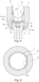
- Fig. 5 shows an assembled pedicle screw 1 according to the second embodiment in longitudinal section. It can be seen how the extensions 6 of the screw head 4 rest diametrically against the receiving sleeve 2, or more precisely, on the support or stop surfaces 16a of the recesses 16, in order to be supported in the diametrical direction of the screw. Furthermore, it can be seen that the bearing surfaces 6a of the extensions 6 of the screw head 4 and the recesses 10 of the insertion sleeve 8 as well as the second bearing surfaces 19 of the support tabs 18 and the slots 20 of the insertion sleeve 8 rest against one another in order to support the screw head 4 on the insertion sleeve 8 in the longitudinal direction of the screw and lead.
- the support tabs 18 are supported at least with the radially outer flat sides 21 on corresponding side walls of the slots 20 in order to increase the stability of the pedicle screw 1 against pivoting in a direction transverse to the intended pivot axis S (transverse pivoting).
- diametrically opposed stop projections 22, which are offset by 90 ° to the slots 14, are also provided, which serve to temporarily hold the insertion sleeve 8 (ie, as long as the connecting rod has not yet been inserted and the grub screw has not yet been screwed in ) in the receiving sleeve 2.
- Fig. 6 shows a cross section of the receiving sleeve 2 in the area in which the screw head 4 is received.
- this illustration shows the shape of the recesses 16, in which the extensions 6 of the screw head 4 are pivotally accommodated.
- the recesses 16 are essentially rectangular in cross section, whereby the radial stops 6b of the extensions 6 of the Screw head rests in every pivot position on the support or stop surfaces 16a formed by the recesses 16.
- the recesses 16 in the first embodiment also have such a shape, but can be made smaller.
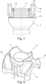
- Fig. 7 shows a side view of a screw head 4 according to a third embodiment of the invention.
- the pedicle screw 1 according to this embodiment is designed to transmit particularly high forces compared to the pedicle screw according to the first and second embodiments and is therefore particularly stable.
- the special features and differences of this embodiment compared to the other two embodiments, in particular the first, will be discussed below, with the same reference numbers being used for comparing features.
- This screw head 4 is also essentially spherical/spherical and forms a proximal end face 17, in which a tool holder or a channel can optionally be embedded. Furthermore, a proximal half of the spherical surface of the screw head 4 is provided with corrugations or ribs 23. As a result, the screw head 4 cannot be freely pivoted about the pivot axis S relative to the insertion sleeve 8, but can be locked into a specific position or pivot position via the ribs 23. Furthermore, the extensions 6 are very large.
- the extensions 6 protrude in the screw diametrical direction beyond the outer circumference of the spherical base body of the screw head 4, so that a screw diametrical extension of the extensions 6 is larger than the diameter of the spherical base body of the screw head 4.
- the extensions 6 protrude beyond the proximal end face 17 of the screw head 4 in the longitudinal direction of the screw.
- the extensions 6 can form additional support surfaces on their radial inside, which, similar to the support tabs 18 of the second embodiment, are supported on corresponding surfaces of the insertion sleeve 8 in order to achieve additional stability of the pedicle screw against transverse pivoting. If necessary, the extensions 6 can also serve to clamp/clamp the insert sleeve 8 between them.
- the spherical screw head 4 is recessed in a cylindrical manner, for example by milling, in order not to hinder a pivoting movement of the receiving sleeve 2 between the extensions 6 of the screw head 4. If necessary, a further storage surface 24 can be provided in addition to the storage surface 6a formed by the extensions 6.
- the third embodiment essentially represents a combination of the first and second embodiments, which enables particularly high stability against transverse pivoting.
- Fig. 8 shows a perspective view of the insert sleeve 8 according to the third embodiment of the invention.
- the recesses 10 of the insertion sleeve 8 are significantly deeper than those of the first and second embodiments, so that the large extensions 6 have space therein.
- the recesses 10 are offset radially outwards, which creates a step in each case.
- the radially inner, more distal part of each step is also cylindrically recessed in order not to hinder a pivoting movement of the receiving sleeve 2 between the extensions 6 of the screw head 4.
- these more distal parts of the steps can optionally be used to form additional bearing surfaces 25, which are adapted to interact with the bearing surfaces 24 of the screw head 4 in the manner of a plain bearing.
- Fig. 9 shows a perspective partial sectional view of the assembled pedicle screw 1 according to the third embodiment of the invention. It can be clearly seen how the receiving surface 9 of the insertion sleeve 8 sits on the ribs 23 of the screw head 4 and how the extensions 6 engage in the recesses 10 of the insertion sleeve 8 in order to communicate both over the bearing surfaces 6a of the extensions 6 with the recesses 10 of the insertion sleeve 8 in the longitudinal direction of the screw as well as via the radially inner support surfaces of the extensions 6 with the steps formed by the recesses 10 in the screw diametrical direction to form pairs of active surfaces.
- Fig. 10 shows an assembled pedicle screw according to the third embodiment in longitudinal section, which shows another special feature of the present embodiment.
- the recesses 16 in the Receiving sleeve 2 forms an undercut. That is, the recesses 16 not only provide the screw diametrically aligned support or stop surface 16a, but also a proximal additional support surface 16b aligned along the length of the screw, against which the bearing surfaces 6a of the extensions 6 of the screw head 4 come into contact. In this way it is ensured that the screw head 4 is supported not only on the insertion sleeve 8 but also directly on the receiving sleeve 2 in the longitudinal direction of the screw.
- the screw head 4 is supported directly by the receiving sleeve 2 and the insertion sleeve 8 both in the proximal and in the screw diametrical direction and maximum stability against transverse pivoting is achieved.
- the recess 16 can be square in cross section, so that the screw head can in principle also be used transversely and the same receiving sleeve can be used for differently aligned polyaxial pedicle screws.
Landscapes
- Health & Medical Sciences (AREA)
- Orthopedic Medicine & Surgery (AREA)
- Life Sciences & Earth Sciences (AREA)
- Surgery (AREA)
- Neurology (AREA)
- Heart & Thoracic Surgery (AREA)
- Engineering & Computer Science (AREA)
- Biomedical Technology (AREA)
- Nuclear Medicine, Radiotherapy & Molecular Imaging (AREA)
- Medical Informatics (AREA)
- Molecular Biology (AREA)
- Animal Behavior & Ethology (AREA)
- General Health & Medical Sciences (AREA)
- Public Health (AREA)
- Veterinary Medicine (AREA)
- Surgical Instruments (AREA)
Description
- Die vorliegende Offenbarung betrifft eine teilweise blockierte Pedikelschraube (kurz: Schraube) der polyaxialen Bauart mit einem Schraubenschaft und einem damit stoffeinstückig verbundenen Schraubenkopf, welcher drehbar und/oder verschwenkbar in einer Aufnahmehülse (Tulpe) gelagert bzw. aufgenommen ist.
- Pedikelschrauben, insbesondere der Polyaxialbauart, werden bei chirurgischen Eingriffen an der Wirbelsäule verwendet, um mehrere Wirbel zueinander lagebestimmt festzulegen. Die Schrauben werden dazu jeweils in Pedikel eines Wirbels eingeschraubt und mittels einem in die Schraubenköpfe bzw. in die damit verbundenen Tulpen eingesetztem Verbindungsstab verbunden. Je nach Einsatzzweck kommen dabei Schrauben mit unterschiedlichen Freiheitsgraden bezüglich einer Relativbewegung zwischen einer Tulpe und einem Schraubenschaft zum Einsatz. Beispielsweise werden zur Derotation von deformierten Wirbelsäulen Schrauben vorgesehen, bei welchen eine Schwenkbewegung zwischen der Tulpe und dem Schraubenschaft in medial-lateraler Richtung blockiert ist (d.h. in seitlicher Richtung bezüglich einer Wirbelsäule bzw. des zugehörigen menschlichen Körpers), in kranial-kaudaler Richtung (d.h. in Längsrichtung oder Höhenrichtung bezüglich der Wirbelsäule) jedoch zur Positionierung während der Operation zugelassen wird. Dies wird dadurch erreicht, indem der Schraubenkopf unrund, beispielsweise mit seitlichen Abflachungen, ausgebildet ist und ein in die Tulpe eingesetztes Inlay oder Insert zur axialen Druckbeaufschlagung des Schraubenkopfs für ein Fixieren der Relativlage zwischen Schraube und Tulpe mit entsprechenden seitlichen Innenflächen ausgebildet ist, die mit den Abflachungen am Schraubenkopf in Auflage kommen.
- Derartige Pedikelschrauben werden mittels eines speziellen Instruments oder Instrumentensatzes implantiert, welches/welcher in der Regel für eine Anzahl von unterschiedlichen Pedikelschrauben standardisiert ist.
- Aus dem Stand der Technik, beispielsweise aus
US 2010/0305621 A1 undUS 9 138 261 B2 -
US 8 048 133 B2 offenbart eine polyaxiale Pedikelschraube, deren runder Kopf an zwei einander schraubendiametral gegenüberliegenden Seiten bearbeitet ist, um einen schraubendiametral verlaufenden Zylinder zu bilden, welcher proximal mit einer entsprechenden Fläche eines Druckelements (Inserts/Inlays) in Anlage kommt und zusammen mit dieser Fläche eine Art Gleitlager bildet, welches Drehungen um eine Zylinderachse erlaubt und Drehungen/Schwenkbewegungen um andere Achsen blockiert. Dieses Blockieren einer Drehung oder Verschwenkung um andere Achsen ist jedoch bei hohen Querkräften voraussichtlich nicht ausreichend stabil und führt zu einem schnellen Ausleiern oder Abnutzen der Verbindung. - Ein weiteres Dokument,
US 5 989 254 A , zeigt eine polyaxiale Pedikelschraube mit einem kugeligen Kopf, in welchem eine zylindrische Sattelfläche bzw. ein Querschlitz mit sattelförmig längsgekrümmten Schlitzgrund zur Aufnahme einer Verbindungsstange, mittels welcher mehrere Pedikelschrauben verbindbar sind, ausgespart ist. Im Fall, dass eine Tulpe über den Schraubenkopf der Pedikelschraube gesetzt und eine Verbindungsstange in die Tulpe quereingelegt ist, wälzt sich die Sattelfläche bei einer Verschwenkung des Schraubenkopfs in der Tulpe um eine schraubendiametral verlaufende Achse an der Verbindungsstange ab. Querkräfte werden hauptsächlich über eine Außenfläche der Verbindungsstange und Seitenflächen der Aussparung für die Sattelfläche, also über einen relativ kurzen Linienkontakt, übertragen. Diese Konstruktion ist gegenüber hohen Querkräften voraussichtlich nicht ausreichend stabil. - Ferner ist aus
US 2015/282844 A1 ein Knochenanker mit den Merkmalen des Oberbegriffs des Anspruchs 1 bekannt. Der untere Bereich des Gehäuses definiert Passelemente, die mit Eingriffselementen an der Knochenschraube zusammenpassen, um die Bewegung des Gehäuses relativ zur Knochenschraube auf eine einzige Ebene zu begrenzen. Die Schraube hat einen im Wesentlichen kugelförmigen Kopf, welcher gegenüberliegende ebenen Flächen und Verlängerungen aufweist, wobei die Verlängerungen der kugelförmigen Oberfläche des Kopfes folgen und die ebenen Oberflächen durch Entfernen von Material unter den Verlängerungen gebildet sind. -
US 2013/023935 A1offenbart ein Wirbelsäulenstabilisierungssystem zur chirurgischen Implantation in die Wirbelsäule mit einem Knochenbefestigungselement, das einen Schaftteil und einen Kopfteil mit einem rechteckig geformten unteren Teil und einem gekrümmten oberen Teil aufweist. Außerdem ist ein Gehäuse mit einer durch Seitenwände definierten Aussparung und einer Öffnung zur Aufnahme des Kopfteils des Knochenbefestigungselements vorgesehen. Das Knochenbefestigungselement ist in einer einzigen Ebene in Bezug auf das Gehäuse und das Sitzelement beweglich. - Zusammenfassend lässt sich sagen, dass bekannte Lösungen in vielen Anwendungssituationen nicht in der Lage sind, ausreichend hohe Querbelastungen bei einem Blockieren von Querverschwenkungen aufzunehmen (das heißt, die erlaubten Querkräfte sind zu niedrig). Ferner weisen diese Lösungen zu viele Einzelteile der polyaxialen Pedikelschraube auf und/oder enthalten Gelenke und sind somit aufwändig zu fertigen und zu montieren. Insbesondere ist häufig die Innengeometrie proximal in den Schraubenkopf eingesetzten des Inserts oder Einsetz- bzw. Haltestücks innerhalb der Tulpe aufwändig. Dies erhöht u.a. die Fertigungskosten. Ggf. ist für eine Implantation dieser Schrauben zudem ein eigenes Instrumentarium notwendig, was zugehörige Fertigungskosten aufgrund geringerer Stückzahlen weiter erhöht.
- Der vorliegenden Erfindung liegt eine Aufgabe zugrunde, Nachteile des Stands der Technik zu reduzieren oder zu vermeiden. Insbesondere soll eine einfache, stabile Pedikelschraube mit einem Schraubenkopf bereitgestellt werden, der innerhalb einer Aufnahmehülse bzw. Tulpe in einer (einzigen) schraubendiametralen Richtung (insbesondere kranial-kaudal) verschwenkbar ist und in einer anderen schraubendiametralen Richtung (insbesondere medial-lateral) auch bei hohen Querkräften/Seitenlasten von mindestens 500N lagefestgelegt ist. Ferner sollen mit der vorliegenden Pedikelschraube insbesondere das Instrumentarium und Madenschrauben zum Fixieren der Schraube, welche vorzugsweise mehrfach gelöst und angezogen werden können sollen, gleicher Systeme verwendbar sein. In anderen Worten sollen die grundsätzlichen Funktionen und die Außengeometrie der "normalen" (systemgleichen) polyaxialen Pedikelschraube beibehalten werden.
- Zusammenfassung der Erfindung.
- Die der Erfindung zugrunde liegende Aufgabe wird durch eine Pedikelschraube mit den Merkmalen des Anspruchs 1 gelöst. Vorteilhafte Ausgestaltungen der Erfindung sind Gegenstand der Unteransprüche und werden später genauer beschrieben.
- Der Grundgedanke der vorliegenden Erfindung liegt im Wesentlichen darin, bei der erfindungsgemäßen Pedikelschraube zusätzliche Stütz-/Lager-/Führungsbereiche zwischen einer Aufnahmehülse oder Tulpe und einem darin gelagerten Schraubenkopf bereitzustellen, welche bei einer auftretenden Querlast eine Querverschwenkung der Aufnahmehülse oder Tulpe relativ zu einem Schraubenschaft, der distal mit dem Schraubenkopf integral verbunden ist, verhindern. Andererseits soll dabei durch diese zusätzlichen Stützbereiche die Beweglichkeit des Schraubenkopfs relativ zu der Aufnahmehülse oder Tulpe der Pedikelschraube um eine Schwenkachse nicht behindert werden. Erfindungsgemäß werden an dem sphärischen Schraubenkopf darüber hinausragende Fortsätze bereitgestellt, welche diese zusätzlichen Stützflächen ausbilden und welche unmittelbar mit der Aufnahmehülse in Stütz-/Lager-/Führungskontakt gebracht werden können oder sind. Auf diese Weise wird der Schraubenkopf nicht nur, wie bei polyaxialen Pedikelschrauben üblich, über einen Stützbereich zwischen dem Schraubenkopf und einer proximal des Schraubenkopfs in der Aufnahmehülse oder Tulpe angeordneten Einsetzhülse/Inlay/Insert, welches dazu dient gegen den Schraubenkopf zu pressen und dadurch dessen Relativlage in der Aufnahmehülse/Tulpe festzulegen, gegen die Querverschwenkung gesichert. Stattdessen sind die Fortsätze zur Ausbildung eines zusätzlichen Stützbereichs mit der Aufnahmehülse/Tulpe bereitgestellt, um eine solche Querverschwenkung zu verhindern. Vorzugsweise können zudem weitere Stützbereiche bereitgestellt werden, welche in unterschiedliche Richtungen ausgerichtet sind, wie beispielsweise eine quer zu der Schraubenlängsachse verlaufende Zylinderfläche, um die Querbelastung stets möglichst optimal aufzunehmen.
- Genauer ausgedrückt, wird die der Erfindung zugrunde liegende Aufgabe durch eine Pedikelschraube der Polyaxialbauart gelöst, welche einen Schraubenschaft hat, an dessen proximalen Ende ein Schraubenkopf mit im Wesentlichen sphärischer Grundform einstückig ausgebildet ist, der in einer Aufnahmehülse oder Tulpe gelagert ist, in der eine Einsetzhülse eingesetzt ist, die zur Festlegung einer Relativ-Schwenkposition zwischen der Aufnahmehülse oder Tulpe und dem Schraubenschaft gegen den Schraubenkopf andrückbar ist. Zwei einander diametral gegenüberliegende Schwenkführungs- oder Schwenkbeschränkungseinheiten sind bereitgestellt, die jeweils zumindest einen radial sowie in Schraubenlängsrichtung über die sphärische Grundform des Schraubenkopfs hinausragenden Fortsatz aufweisen, wobei die Fortsätze an ihren jeweiligen, vorzugsweise teilzylinderförmigen, radialen Außenflächen Anschläge bilden. Die Fortsätze sind derart positioniert, dass sie eine Relativ-Verschwenkung von Schraubenschaft und Tulpe oder Aufnahmehülse nur in der Schwenkebene erlauben und dass sie bei einer Relativ-Verschwenkung in einer anderen Schwenkebene (einer Querverschwenkung) gegen eine radial innere Umfangsseite der Tulpe oder Aufnahmehülse stützend anschlagen. Durch die auf diese Weise erzeugten Stützbereiche/Anschläge zwischen dem Schraubenkopf und der Aufnahmehülse/Tulpe kann erreicht werden, dass sehr hohe Querlasten (mindestens 500N) übertragbar sind und Querverschwenkungen effektiv blockiert werden können. Es wird folglich eine hohe Seitenstabilität durch dicke Fortsätze oder Führungslaschen erreicht.
- Ferner sind keine Änderungen an der Außengeometrie der Gesamtschraube notwendig, weshalb für eine Implantation der Pedikel- oder Knochenschraube systemgleiche Standardinstrumente verwendet werden können. Entsprechend sind für eine solche Pedikelschraube nur schraubeninterne Änderungen der Konstruktion im Vergleich mit einer systemgleichen Standardschraube vorgenommen, ohne dass eine komplexe Innengeometrie am Insert notwendig wäre. Die Einsetzhülse (Insert/Inlay) kann geometrisch im Wesentlichen unverändert oder nur mit relativ geringfügigen Änderungen sowohl für eine Uniplanarschraube als auch für eine Polyaxialschraube verwendet werden, weshalb ggf. höhere Stückzahlen und niedrigere Kosten erzielt werden können. Ferner muss der Montageprozess minimal oder sogar gar nicht verändert werden, weshalb keine Umstellung der Montage notwendig ist. Auch die Anzahl der benötigten Teile (Aufnahmehülse/Tulpe/Body, Einsetzhülse/Insert/Inlay und Schraubenkopf und -schaft) ist gering. Weiterhin haben die einzelnen Komponenten, das heißt, der Schraubenkopf, die Einsetzhülse (Inlay/Insert) und die Aufnahmehülse (Tulpe), eine einfache Form, wodurch die Pedikelschraube einfach zu fertigen ist.
- Vorzugsweise bilden die Fortsätze proximal teilweise zylinderförmige Lagerflächen, welche die Relativ-Verschwenkung des Schraubenschafts und der Tulpe oder Aufnahmehülse in der Schwenkebene führen und welche in proximaler Richtung an stirnseitigen oder distalen, entsprechend teilzylindrisch ausgebildeten Rücksprüngen der Einsetzhülse geführt sind, um nach Art eines Gleitlagers zusammenzuwirken. Eine so gebildete Wirkflächenpaarung dient sowohl zur gleichmäßigen, möglichst reibungsarmen Führung der Verschwenkung um die Schwenkachse als auch zum Abstützen oder Blockieren der Querschwenkung, insbesondere um eine Achse quer zu der Schwenkachse. Da die Fortsätze einander diametral gegenüberliegen, entsteht zudem zwischen den zumindest zwei Fortsätzen bzw. den entsprechenden Lagerflächen ein Hebel, über welchen auf die Schraube wirkende Querkräfte besonders gut übertragen werden können. Demgemäß kann eine Verschwenkung des Schraubenkopfes relativ zu der Aufnahmehülse/Tulpe um eine Achse quer zu der Schwenkachse effektiv blockiert werden.
- Es hat sich als zweckmäßig erwiesen, dass die Tulpe oder Aufnahmehülse an einer Innenumfangsfläche zumindest zwei einander diametral gegenüberliegende Aussparungen aufweist, welche ausreichend groß dimensioniert sind, dass die Fortsätze in jeder Schwenkposition darin aufgenommen sind. Ohne diese Aussparungen wäre aufgrund der Fortsätze die Verschwenkung des Schraubenkopfs relativ zu der Aufnahmehülse/Tulpe nicht oder nur geringfügig möglich. Demgemäß wird die Verschwenkbarkeit des Schraubenkopfes in der Aufnahmehülse/Tulpe insbesondere durch die Aussparungen gewährleistet. Bevorzugter Weise sind die Aussparungen und die Fortsätze derart dimensioniert und positioniert, dass dir Fortsätze in jeder Schwenkposition an der radial inneren Umfangsseite der Tulpe oder Aufnahmehülse anschlagen können. Dies kann beispielsweise erzielt werden, indem die Aussparungen im Wesentlichen rechteckig sind. Dadurch wird in der Aufnahmehülse/Tulpe eine große, insbesondere eine sich in Schraubenlängsrichtung erstreckende Anschlags- oder Anlagefläche für die Fortsätze des Schraubenkopfs bereitgestellt, wodurch hohe auftretende Querkräfte (mindestens 500N) unmittelbar und stabil auf die Aufnahmehülse/Tulpe übertragen werden können. Demgemäß kann über eine Wechselwirkung zwischen den Fortsätzen des Schraubenkopfes und der Aufnahmehülse sowie, wie vorstehend beschrieben, über eine Wechselwirkung zwischen den Fortsätzen des Schraubenkopfes und der Einsetzhülse, eine Verschwenkung um eine Achse quer zu der Schwenkachse effektiv unterbunden werden.
- Es ist von Vorteil, wenn durch die Fortsätze eine Verschwenkung des Schraubenkopfs in einer medial-lateralen Richtung blockiert wird und eine Verschwenkung in einer kranial-kaudalen Richtung zugelassen wird. Dies ist insbesondere auf dem Einsatzgebiet der Wirbelsäulenderotation vorteilhaft. Konstruktiv wird dies dadurch erreicht, dass die Aufnahmehülse oder Tulpe und vorzugsweise die Einsetzhülse in Umfangsrichtung um 90° zu den im zusammengebauten Zustand darin angeordneten Fortsätzen versetzt vorzugsweise U-förmige Schlitze zur Aufnahme einer Verbindungsstange aufweist, durch welche mehrere Pedikelschrauben miteinander verbindbar sind. Grundsätzlich kann dies für andere Anwendungszwecke auch umgekehrt vorgesehen werden. Das heißt, es sind verschiedene Ausrichtungen des Schraubenkopfs zu der Aufnahmehülse/Tulpe möglich. Ferner soll bevorzugter Weise bei der Pedikelschraube eine Verschwenkung des Schraubenschafts relativ zu der Aufnahmehülse oder Tulpe in der einen Schwenkebene von zumindest +/- 22°, vorzugsweise zumindest +/- 30°, möglich sein. Auch dieser Bereich orientiert sich an für die Wirbelsäulenderotation vorteilhaften Werten.
- Nach einer vorteilhaften Ausgestaltung der Erfindung ist ein Durchmesser der proximalen Lagerflächen der Fortsätze kleiner als ein Durchmesser der sphärische Grundform des Schraubenkopfs. Das heißt, die Fortsätze sind im Wesentlichen halbmondförmig oder ohrenartig an dem sphärischen Grundkörper des Schraubenkopfes (insbesondere in der Nähe von dessen schraubendiametralem Außenumfang) angeordnet, wobei ein runder Teil des Halbmonds oder der Ohren in proximaler Richtung ausgerichtet ist. Der Durchmesser der sphärischen Grundform des Schraubenkopfs, insbesondere eine Außenkontur des gesamten Schraubenkopfs, ist in diesem Fall vorzugsweise kleiner oder gleich einem Innendurchmesser der Aufnahmehülse/Tulpe. Dadurch sind an dem Schraubenkopf nur wenige Ecken und Kanten ausgebildet, was dessen Fertigung und ggf. eine Sterilisierung vereinfacht. Ferner ist ein Nachbearbeitungsaufwand der Aufnahmehülse/Tulpe minimiert.
- Bevorzugter Weise sind an dem Schraubenkopf zusätzliche Stützlaschen ausgebildet, welche zu den Fortsätzen schraubendiametral nach innen versetzt sind und welche in proximaler Richtung über die Fortsätze hinausragen. Insbesondere sollen diese Stützlaschen proximal teilweise zylinderförmige zweite Lagerflächen bilden, um mit stirnseitigen, entsprechend teilzylindrisch ausgebildeten Schlitzen der Einsetzhülse nach Art eines Gleitlagers zusammenzuwirken. Ein Durchmesser der zweiten Lagerflächen ist größer als der der vorstehend beschriebenen ersten Lagerflächen der Fortsätze. Dadurch können weitere Flächen zur Führung und Kraftübertragung bei der vorgesehenen Schwenkbewegung bereitgestellt werden und werden Querbelastungen besser abgestützt.
- Beispielsweise kann es von Vorteil sein, wenn die Stützlaschen schraubenradial außen und ggf. auch innen flach sind, um sich an korrespondierenden Flächen der Schlitze abzustützen, um die Verschwenkung in der anderen Schwenkebene bzw. die Querverschenkung zu blockieren. Das heißt, die Stützlaschen bilden eine schraubendiametrale ebene Fläche an dem Schraubenkopf aus, um einen zusätzlichen radialen Stütz- oder Führungsbereich zum Übertragen von Querlasten bereitzustellen.
- Nach einer weiteren vorteilhaften Ausgestaltung der Erfindung können die Fortsätze schraubendiametral nach außen und vorzugsweise proximal über einen Außendurchmesser des sphärischen Grundkörpers des Schraubenkopfs hinausragen. In anderen Worten wird durch diese schraubendiametrale Verbreiterung des Schraubenkopfes ein Hebel zwischen den beiden Fortsätzen bzw. den durch diese ausgebildeten Lagerflächen bereitgestellt. Demgemäß können über die Lagerflächen der Fortsätze des Schraubenkopfs noch größere Querlasten abgestützt werden als nach der vorstehend beschriebenen, ersten vorteilhaften Ausgestaltung.
- Es kann ferner eine Außenkontur des gesamten Schraubenkopfs (d.h., des sphärischen Grundkörpers und der darüber schraubendiametral hinausragenden Fortsätze) größer als der Innendurchmesser der Tulpe oder Aufnahmehülse sein. Demgemäß ist es sinnvoll, wenn die Aussparungen durch eine in einer Innenumfangswand der Aufnahmehülse/Tulpe ausgesparte Hinterschneidung, welche vorzugsweise rechteckig, weiter vorzugsweise quadratisch ist, ausgebildet sind, um die Fortsätze aufnehmen zu können. Grundsätzlich sind auch andere Ausgestaltungen möglich. Bei einer quadratischen Hinterschneidung ist jedoch ggf. von Vorteil, dass die Hülse auch um 90° verdreht montiert werden kann, um die Beweglichkeit des Schraubenkopfs in der gleichen Aufnahmehülse/Tulpe in unterschiedlichen (Schwenk-) Richtungen zu ermöglichen.
- Insbesondere stützen sich die Fortsätze in der durch die Aussparungen in der Aufnahmehülse oder Tulpe gebildete Hinterschneidung sowohl schraubendiametral nach außen als auch in Schraubenlängsrichtung ab. In anderen Worten ausgedrückt sind die Aussparungen derart in eine Innenumfangsfläche der Aufnahmehülse/Tulpe eingelassen, dass diese sowohl in schraubendiametraler als auch in der Schraubenlängsrichtung Anschläge oder Stützflächen ausbilden. Demgemäß wird nach dieser Ausgestaltung durch die Aussparungen neben der schraubendiametralen Führung oder Abstützung der Fortsätze des Schraubenkopfs auch deren Führung oder Abstützung in der Schraubenlängsrichtung übernommen. Das heißt, sämtliche Relativbewegungen des Schraubenkopfs werden sowohl über die Einsetzhülse (Inlay/Insert) als auch über die Aufnahmehülse/Tulpe geführt oder gestützt und die zu übertragenen Lasten werden aufgeteilt. Entsprechend wird die Steifigkeit der Abstützung des Schraubenkopfs bei Querlasten weiter erhöht.
- Vorzugsweise sind die Fortsätze jeweils schraubenradial innen flach ausgebildet und werden an gegenüberliegenden Flächen der Rücksprünge geführt. Das heißt, die Fortsätze bilden bei dieser Ausgestaltung sowohl die radial oder schraubendiametral nach außen gerichteten Anschläge als auch radial oder schraubendiametral nach innen gerichtete Führungsflächen aus. Diese können ggf. zusätzlich Stützfunktionen übernehmen. Die Fortsätze sind folglich derart gestaltet, dass sie sowohl die Vorteile der halbmondförmigen Fortsätze also auch die Vorteile der vorstehend beschriebenen Stützlaschen bereitstellen. Dadurch kann die Steifigkeit der Abstützung des Schraubenkopfs bei Querlasten weiter erhöht werden.
- Alternativ oder zusätzlich kann bei jeder der vorstehend beschriebenen Ausgestaltungen der Erfindung ein Teil des Schraubenkopfs zylindrische abgefräst sein, um an dem Schraubenkopf eine weitere Lagerfläche bereitzustellen, welche mit korrespondierenden, stirnseitig an der Einsetzhülse bzw. dem Insert/Inlay ausgebildeten Lagerflächen als Gleitlager zusammenwirkt.
- Zusammenfassend kann gesagt werden, dass die der Erfindung zugrunde liegende Aufgabe durch eine Anbringung von seitlichen Laschen am Kopfende einer Knochen-/Pedikelschraube und dazu korrespondierenden Innenräumen an einer Aufnahmehülse bzw. an einem Body bzw. einer Tulpe, sowie durch gleichzeitig korrespondierende Aussparungen am Insert. Die Laschen stützten sich sowohl am Insert als auch am Body in lateraler Richtung ab und sperren eine Bewegung in lateraler Richtung bei gleichzeitig freier Beweglichkeit in kranial-kaudaler Richtung. Dabei bilden der Schraubenkopf und die Laschen eine Einheit und weisen außen eine zylindrische Kontur auf. Durch die erfindungsgemäße Gestaltung sind keine zusätzlichen Verbindungselemente wie Stifte, Achsen und ähnliches notwendig. Zur Montage der gesamten Pedikelschraube (nach einer Ausgestaltung, siehe die nachfolgend beschrieben dritte Ausführungsform) kann die Knochenschraube trotz eines Außendurchmessers der Laschen, der größer ist als der Innendurchmesser des Bodys, mittels einer Drehbewegung der Schraube gegenüber dem Body ohne Werkzeug montiert werden. Aufgrund des größeren Laschendurchmessers stützt sich die Schraube bei Verwendung nicht nur radial am Body ab, sondern auch axial über die Stirnseiten der Laschen.
- Nachfolgend wird die vorliegende Erfindung anhand bevorzugter Ausführungsformen beschrieben, welche nachfolgend veranschaulichend beschrieben werden. Es ist anzumerken, dass Merkmale verschiedener Ausführungsformen kombinierbar sind und diverse Änderungen vorgenommen werden können, ohne vom Schutzumfang der Erfindung abzuweichen.
-
Fig. 1 zeigt eine perspektivische Teilschnittansicht der Pedikelschraube nach einer ersten Ausführungsform der Erfindung; -
Fig. 2 zeigt eine Aufnahmehülse oder Tulpe im Längsschnitt nach der ersten Ausführungsform; -
Fig. 3 zeigt einen Schraubenkopf nach einer zweiten Ausführungsform der Erfindung; -
Fig. 4 zeigt eine Einsetzhülse nach der zweiten Ausführungsform der Erfindung; -
Fig. 5 ist eine Längsschnittansicht der zusammengebauten Pedikelschraube nach der zweiten Ausführungsform der Erfindung; -
Fig. 6 zeigt einen Querschnitt der Aufnahmehülse nach der zweiten Ausführungsform im Bereich der Aussparungen; -
Fig. 7 ist eine Seitenansicht eines Schraubenkopfs nach einer dritten Ausführungsform der Erfindung; -
Fig. 8 zeigt eine Einsetzhülse nach der dritten Ausführungsform der Erfindung; -
Fig. 9 zeigt eine perspektivische Teilschnittansicht der Pedikelschraube nach der dritten Ausführungsform; und -
Fig. 10 zeigt eine Längsschnittansicht der Pedikelschraube nach der dritten Ausführungsform der Erfindung. -
Fig. 1 zeigt eine perspektivische Teilschnittansicht einer erfindungsgemäßen Pedikelschraube 1 in einem abgewinkelten Zustand. Die Pedikelschraube 1 weist eine in dieser Darstellung längsgeschnittene Tulpe oder Aufnahmehülse 2 auf, deren Innenumfang an einem distalen Ende konisch verengt ist, um eine Anlagefläche 3 für einen kugeligen Schraubenkopf 4 der Pedikelschraube 1 zu bilden. Die Pedikelschraube 1 wurde aus proximaler Richtung derart in die Aufnahmehülse 2 eingeführt, dass der kugelige Schraubenkopf 4 distal an der Anlagefläche 3 anliegt und ein damit integral ausgebildeter Schraubenschaft 5 distal aus der Aufnahmehülse 2 herausragt, sodass der Schraubenkopf 4 und Schraubenschaft 5 relativ zu der Aufnahmehülse 2 verschwenkbar sind. - Der Schraubenkopf 4 ist auch proximal zumindest teilweise kugelig ausgebildet, und weist ferner an einander schraubendiametral gegenüberliegenden Seiten zwei Fortsätze 6 auf, welche sich ausgehend von einem Außenumfang des Schraubenkopfs 4 halbmondförmig in proximaler Richtung erstrecken. D. h., proximal ausgerichtete Flächen der Fortsätze 6 bildet jeweils Lagerflächen 6a, welche zum Abstützen des Schraubenkopfs 4 an einer Einsetzhülse 8 (Inlay/Insert) dienen. Diese Lagerflächen 6a bzw. deren Durchmesser definiert bei der vorliegenden Pedikelschraube 1 eine Schwenkachse S, um welche der Schraubenkopf 4 bezüglich der Aufnahmehülse 2 verschwenkbar ist. Um dies zu veranschaulichen ist die Pedikelschraube 1 in
Fig. 1 in einem verschwenkten Zustand dargestellt, was durch die Längsachsen des Schraubenschafts A und der Aufnahmehülse B deutlich wird, welche sich an einer Schwenkachse, d. h. der Mittelachse der Lagerflächen 6a, schneiden. Darüber hinaus bilden die Fortsätze 6 eine vorzugsweise teilzylinderförmige radiale Außenfläche oder einen vorzugsweise teilzylinderförmigen radialen Anschlag 6b, die/der als eine Stützfläche zum Abstützen des Schraubenkopfs 4 an der Aufnahmehülse 2 dienen. - Die Einsetzhülse 8 bildet an ihrer distalen Seite zur Aufnahme des runden Schraubenkopfs 4 teilweise eine hohlkugelförmige Aufnahmefläche 9 aus, welche hier nicht dargestellt ist, aber im Wesentlichen der korrespondierenden Aufnahmefläche 9 aus
Fig. 4 undFig. 8 entspricht. Ferner ist ein stirnseitiger, distaler Rand der Einsetzhülse 8 nicht durchgehend ausgebildet, sondern weist zwei einander diametral gegenüberliegende Rücksprünge 10 auf, welche mit dem halbmondförmigen oder ohrenartigen Fortsätzen 6, genauer, deren Lagerflächen 6a, korrespondieren. Die Rücksprünge 10 wirken mit den Lagerflächen 6a nach Art eines Gleitlagers zusammen, um die Verschwenkbarkeit der Aufnahmehülse 2 und des Schraubenkopfs 4 zu gewährleisten. - An einem proximalen Bereich der Einsetzhülse 8 weist diese zwei zu den Rücksprüngen 10 um 90° versetzte laterale Ausbuchtungen 11 auf, welche in korrespondierende Sattelflächen 12 innerhalb der Aufnahmehülse 2 lagebestimmt aufgenommen sind. Die Einsetzhülse 8 hat ferner eine halbzylindrische Öffnung 13, welche durch die Ausbuchtungen 11 verläuft, um eine Verbindungstange aufzunehmen, über welche bei einer Implantation oder Operation zwei Pedikelschrauben 1 miteinander verbunden werden können. Die Aufnahmehülse 2 hat ferner an der gleichen Winkelposition wie die Sattelflächen 12 zwei von proximaler Seite aus eingebrachte, U-förmige Schlitze 14, in welche die Verbindungstange einlegbar ist. An einem proximalen Bereich innerhalb der Aufnahmehülse 2 ist ein Gewinde 15 vorgesehen, in welches eine Madenschraube zum Verspannen der Pedikelschraube 1 und der Verbindungstange eingeschraubt werden kann.
-
Fig. 2 zeigt einen Längsschnitt der Aufnahmehülse 2 nach der ersten Ausführungsform der Erfindung. Neben den bereits vorstehend beschriebenen Merkmalen geht aus dieser Ansicht hervor, dass in einem Innenumfangsbereich der Aufnahmehülse 2, in welchem der Schraubenkopf 4 aufgenommen ist, 2 einander diametral gegenüberliegende Aussparungen 16 (hier nur eine dargestellt) vorgesehen sind. Diese Aussparungen 16 dienen dazu, die Fortsätze 6 aufzunehmen, um die Beweglichkeit oder Verschwenkbarkeit des Schraubenkopfs um die Schwenkachse S zu gewährleisten. Gleichzeitig bilden die Aussparungen 16 eine Stütz- oder Anschlagsfläche 16a, um dem Schraubenkopf 4 über die Fortsätze 6, genauer, die radialen Anschläge 6b, unmittelbar an der Aufnahmehülse 2 abzustützen. - Die in
Fig. 3 bis Fig. 6 dargestellte zweite Ausführungsform der Erfindung entspricht zu großen Teilen der der ersten Ausführungsform, weshalb nachfolgend lediglich auf deren Unterschiede eingegangen wird und dieselben Bezugszeichen vergleiche Merkmale verwendet werden. -
Fig. 3 zeigt dem Schraubenkopf 4 nach der zweiten Ausführungsform der Erfindung in einer perspektivischen Ansicht. Hier ist zu sehen, dass der Schraubenkopf 4 eine proximale Stirnfläche 17 aufweist, in welcher beispielsweise eine Werkzeugaufnahme oder ein Kanal zum Einpressen von Knochenzement eingelassen sein kann. Eine solche Stirnfläche 17 kann auch bei der ersten Ausführungsform vorgesehen sein. Ferner weist der Schraubenkopf 4 zusätzlich zu den Fortsätzen 6 dazu radial nach innen versetzte Stützlaschen 18 auf. Diese Stützlaschen 18 erstrecken sich in proximaler Richtung über die proximale Stirnfläche 17 des Schraubenkopfs 4 hinaus und bilden an ihrem proximalen Ende ebenfalls Zylindermantelflächen oder zweite Lagerflächen 19 aus, um eine weitere Führungs- oder Stütz- oder Lagerfläche zum Führen oder Stützen oder Lagern an der Einsetzhülse 8 zu bilden. In schraubendiametraler Richtung sind die Stützlaschen 18 beidseitig flach ausgebildet. -
Fig. 4 zeigt eine Einsetzhülse 8 nach der zweiten Ausführungsform der Erfindung. Diese weist neben der Aufnahmefläche 9 und den Rücksprüngen 10 distal eingelassene Schlitze 20 auf, welche zu den Rücksprüngen 10 radial nach innen versetzt sind. D. h., eine Position der Schlitze 20 korrespondiert zu einer Position der Stützlaschen 18. Demgemäß bilden die Schlitze 20 in distaler Richtung eine innenzylindrische Fläche aus, welche mit dem Stützlaschen 18, genauer, der Zylindermantelfläche oder der zweiten Lagerfläche 19 der Stützlaschen 18, nach Art eines Gleitlagers zusammenwirken. -
Fig. 5 zeigt eine zusammengebaute Pedikelschraube 1 nach der zweiten Ausführungsform im Längsschnitt. Darin ist erkennbar, wie die Fortsätze 6 des Schraubenkopfs 4 schraubendiametral an der Aufnahmehülse 2, genauer, an den Stütz- oder Anschlagsflächen 16a der Aussparungen 16, anliegen, um sich in schraubendiametrale Richtung abzustützen. Ferner ist erkennbar, dass die Lagerflächen 6a der Fortsätze 6 des Schraubenkopfs 4 und die Rücksprünge 10 der Einsetzhülse 8 sowie die zweite Lagerflächen 19 der Stützlaschen 18 und die Schlitze 20 der Einsetzhülse 8 aneinander anliegen, um den Schraubenkopf 4 in Schraubenlängsrichtung an der Einsetzhülse 8 abzustützen und führen. Darüber hinaus ist erkennbar, dass die Stützlaschen 18 sich zumindest mit dem radial äußeren flachen Seiten 21 an korrespondierenden Seitenwänden der Schlitze 20 abstützen, um die Stabilität der Pedikelschraube 1 gegen ein Verschwenken in einer Richtung quer zu der vorgesehenen Schwenkachse S (Querverschwenken) zu erhöhen. In der Aufnahmehülse 2 sind ferner nach dieser Ausführungsform 2 einander diametral gegenüberliegende, um 90° zu den Schlitzen 14 versetzte Stoppvorsprünge 22 bereitgestellt, welche dazu dienen, die Einsetzhülse 8 provisorisch (d. h., solange die Verbindungstange noch nicht eingesetzt und die Madenschraube noch nicht eingeschraubt ist) in der Aufnahmehülse 2 zu halten. -
Fig. 6 zeigt einen Querschnitt der Aufnahmehülse 2 in dem Bereich, in welchem der Schraubenkopf 4 aufgenommen wird. Insbesondere geht aus dieser Darstellung die Form der Aussparungen 16 hervor, in welchem die Fortsätze 6 des Schraubenkopfs 4 schwenkbar aufgenommen sind. Die Aussparungen 16 sind im Querschnitt im Wesentlichen rechteckig, wodurch die radialen Anschläge 6b der Fortsätze 6 des Schraubenkopfs in jeder Schwenkposition an der durch die Aussparungen 16 ausgebildeten Stütz- oder Anschlagsflächen 16a anliegt. Auch die Aussparungen 16 in der ersten Ausführungsform weisen eine solche Form auf, können jedoch kleiner ausgebildet sein. -
Fig. 7 zeigt eine Seitenansicht eines Schraubenkopfs 4 nach einer dritten Ausführungsform der Erfindung. Die Pedikelschraube 1 nach dieser Ausführungsform ist verglichen mit der Pedikelschraube nach der ersten und zweiten Ausführungsform dazu ausgebildet, besonders hohe Kräfte zu übertragen, und ist deshalb besonders stabil ausgebildet. Nachfolgend wird auf die Besonderheiten und Unterschiede dieser Ausführungsform gegenüber den anderen beiden Ausführungsformen, insbesondere der ersten, eingegangen, wobei dieselben Bezugszeichen vergleiche Merkmale verwendet werden. - Auch dieser Schraubenkopf 4 ist im Wesentlichen kugelförmig/sphärisch und bildet an eine proximale Stirnfläche 17, in welcher gegebenenfalls eine Werkzeugaufnahme oder ein Kanal eingelassen sein können. Ferner ist eine proximale Hälfte der Kugeloberfläche des Schraubenkopfs 4 mit einer Riffelung oder Rippen 23 versehen. Durch diese ist der Schraubenkopf 4 gegenüber der Einsetzhülse 8 nicht frei um die Schwenkachse S verschwenkbar, sondern kann über die Rippen 23 in einer bestimmten Stellung oder Schwenkposition eingerastet werden. Ferner sind die Fortsätze 6 sehr groß ausgebildet. D. h., sie ragen in schraubendiametraler Richtung über dem Außenumfang des sphärischen Grundkörpers des Schraubenkopfs 4 hinaus, sodass eine schraubendiametrale Erstreckung der Fortsätze 6 größer als der Durchmesser des sphärischen Grundkörpers des Schraubenkopfs 4 ist. Zudem ragen die Fortsätze 6 in Schraubenlängsrichtung über die proximale Stirnfläche 17 des Schraubenkopfs 4 hinaus. Auf diese Weise können die Fortsätze 6 an ihrer radialen Innenseite zusätzliche Stützflächen ausbilden, welche sich ähnlich den Stützlaschen 18 der zweiten Ausführungsform an korrespondierenden Flächen der Einsetzhülse 8 abstützen, um eine zusätzliche Stabilität der Pedikelschraube gegen eine quer Verschwenkung zu erreichen. Ggf. können die Fortsätze 6 auch dazu dienen, die Einsetzhülse 8 dazwischen einzuspannen/einzuklemmen.
- Radial innerhalb der Fortsätze 6 ist der kugelige Schraubenkopf 4 zylindrisch ausgespart, z.B. durch Fräsen, um eine Schwenkbewegung der Aufnahmehülse 2 zwischen den Fortsätzen 6 des Schraubenkopfs 4 nicht zu behindern. Gegebenenfalls kann dadurch zusätzlich zu dem durch die Fortsätze 6 gebildeten Lagerflächen 6a eine weitere Lagerfläche 24 bereitgestellt sein. Zusammenfassend kann man sagen, dass die dritte Ausführungsform im Wesentlichen eine Kombination der ersten und zweiten Ausführungsform darstellt, welche eine besonders hohe Stabilität gegen eine Querverschwenkung ermöglicht.
-
Fig. 8 zeigt eine perspektivische Ansicht der Einsetzhülse 8 nach der dritten Ausführungsform der Erfindung. Darin ist gut erkennbar, dass die Rücksprüngen 10 der Einsetzhülse 8 deutlich tiefer als die der ersten und zweiten Ausführungsform sind, damit die großen Fortsätze 6 darin Platz haben. Ferner sind die Rücksprünge 10 radial nach außen versetzt, wodurch jeweils eine Stufe entsteht. Dabei ist auch der radial innenliegende, weiter distal liegende Teil von jeder Stufe zylindrisch ausgespart, um eine Schwenkbewegung der Aufnahmehülse 2 zwischen den Fortsätzen 6 des Schraubenkopfs 4 nicht zu behindern. Zudem können gegebenenfalls durch diese weiter distal liegenden Teile der Stufen zusätzliche Lagerflächen 25 ausgebildet werden, welche dazu angepasst sind, mit dem Lagerflächen 24 des Schraubenkopfs 4 nach Art eines Gleitlagers zusammenzuwirken. -
Fig. 9 zeigt eine perspektivische Teil Schnittansicht der zusammengebauten Pedikelschraube 1 nach der dritten Ausführungsform der Erfindung. Darin ist gut zu erkennen, wie die Aufnahmefläche 9 der Einsetzhülse 8 auf den Rippen 23 des Schraubenkopfs 4 sitzt und wie die Fortsätze 6 in die Rücksprüngen 10 der Einsetzhülse 8 greifen, um sowohl über die Lagerflächen 6a der Fortsätze 6 mit den Rücksprüngen 10 der Einsetzhülse 8 in Schraubenlängsrichtung als auch über die radial innenliegenden Stützflächen der Fortsätze 6 mit den durch die Rücksprüngen 10 ausgebildeten Stufen in schraubendiametrale Richtung Wirkflächenpaare auszubilden. -
Fig. 10 zeigt eine zusammengebaute Pedikelschraube nach der dritten Ausführungsform im Längsschnitt, woraus eine weitere Besonderheit der vorliegenden Ausführungsform hervorgeht. Und zwar ist erkennbar, dass die Aussparungen 16 in der Aufnahmehülse 2 eine Hinterschneidung bilden. D. h., durch die Aussparungen 16 wird nicht nur die schraubendiametral ausgerichtete Stütz- oder Anschlagsfläche 16a, sondern auch eine proximale, schraubenlängs ausgerichtete Zusatzstützfläche 16b bereitgestellt, an welcher die Lagerflächen 6a der Fortsätze 6 des Schraubenkopfs 4 in Anlage kommt. Auf diese Weise wird gewährleistet, dass der Schraubenkopf 4 sich auch in Schraubenlängsrichtung nicht nur an der Einsetzhülse 8 sondern auch unmittelbar an der Aufnahmehülse 2 abstützt. D. h., nach dieser Ausführungsform wird der Schraubenkopf 4 sowohl in proximaler als auch in schraubendiametrale Richtung unmittelbar durch die Aufnahmehülse 2 und die Einsetzhülse 8 gestützt und wird eine maximale Stabilität gegen eine Querverschwenkung erreicht. Die Aussparung 16 kann im Querschnitt quadratisch sein, sodass der Schraubenkopf grundsätzlich auch quer eingesetzt werden kann und die gleiche Aufnahmehülse für verschieden ausgerichtete polyaxiale Pedikelschrauben verwendbar ist. -
- 1
- Pedikelschraube
- 2
- Aufnahmehülse/Tulpe
- 3
- Anlagefläche der Aufnahmehülse
- 4
- Schraubenkopf
- 5
- Schraubenschaft
- 6
- Fortsatz des Schraubenkopfs
- 6a
- Lagerflächen des Schraubenkopfs
- 6b
- diametrale Anschläge des Schraubenkopfs
- 7 8
- Einsetzhülse/Insert/Inlay
- 9
- Aufnahmefläche der Einsetzhülse
- 10
- Rücksprung der Einsetzhülse
- 11
- Ausbuchtung Einsetzhülse
- 12
- Sattelfläche der Aufnahmehülse
- 13
- halb zylindrische Öffnung der Einsetzhülse
- 14
- U-förmige Schlitz der Aufnahmehülse
- 15
- Gewinde der Aufnahmehülse
- 16
- Aussparung der Aufnahmehülse
- 16a
- schraubendiametrale Stütz- oder Anschlagsfläche der Aussparung
- 16b
- proximale Stützfläche der Aussparung
- 17
- proximale Stirnfläche des Schraubenkopfs
- 18
- Stützlasche des Schraubenkopfs
- 19
- zweite Lagerfläche der Stützlasche
- 20
- Schlitz der Einsetzhülse
- 21
- Flache Seiten der Stützlasche
- 22
- Stoppvorsprung der Aufnahmehülse
- 23
- Rippen des Schraubenkopfs
- 24
- Lagerfläche (oder Aussparung) des Schraubenkopfs
- 25
- Lagerfläche (oder Stufe) der Einsetzhülse
Claims (13)
- Pedikelschraube (1) der Polyaxialbauart mit einem Schraubenschaft (5), an dessen proximalen Ende ein Schraubenkopf (4) mit im Wesentlichen sphärischer Grundform einstückig ausgebildet ist, der in einer Aufnahmehülse oder Tulpe (2) gelagert ist, in der eine Einsetzhülse (8) eingesetzt ist, die zur Festlegung einer Relativ-Schwenkposition zwischen der Aufnahmehülse oder Tulpe (2) und dem Schraubenschaft (5) gegen den Schraubenkopf (4) andrückbar ist,
wobei der Schraubenkopf zwei einander diametral gegenüberliegende Schwenkführungs- oder Schwenkbeschränkungseinheiten (127) aufweist, dadurch gekennzeichnet, dass die zwei einander diametral gegenüberliegenden Schwenkführungs- oder Schwenkbeschränkungseinheiten jeweils zumindest einen radial sowie in Schraubenlängsrichtung über die sphärische Grundform des Schraubenkopfs (4) hinausragenden Fortsatz (6) aufweisen, wobei die Fortsätze (6) an ihren jeweiligen, vorzugsweise teilzylinderförmigen, radialen Außenflächen Anschläge (6b) bilden und derart positioniert sind, dass sie eine Relativ-Verschwenkung des Schraubenschafts (5) und der Tulpe oder Aufnahmehülse (2) nur in einer Schwenkebene erlauben und dass sie bei einer Relativ-Verschwenkung in einer anderen Schwenkebene gegen eine radial innere Umfangsseite der Tulpe oder Aufnahmehülse (2) stützend anschlagen. - Pedikelschraube (1) nach Anspruch 1, wobei die Fortsätze (6) proximal teilweise zylinderförmige Lagerflächen (6a) bilden, welche die Relativ-Verschwenkung des Schraubenschafts (5) und des Tulpe oder Aufnahmehülse (2) in der Schwenkebene führen und welche in proximaler Richtung an stirnseitigen oder distalen, entsprechend teilzylindrisch ausgebildeten Rücksprüngen (10) der Einsetzhülse (8) geführt sind, um nach Art eines Gleitlagers zusammenzuwirken.
- Pedikelschraube (1) nach einem der Ansprüche 1 und 2, wobei die Tulpe oder Aufnahmehülse (2) an einer Innenumfangsfläche zumindest zwei einander diametral gegenüberliegende Aussparungen (16) aufweist, welche ausreichend groß dimensioniert sind, dass die Fortsätze (6) in jeder Schwenkposition darin aufgenommen sind.
- Pedikelschraube (1) nach einem der vorstehenden Ansprüche, wobei eine Verschwenkung des Schraubenschafts (5) relativ zu der Aufnahmehülse oder Tulpe (2) in der einen Schwenkebene von zumindest +/- 22°, vorzugsweise zumindest +/- 30°, zugelassen wird.
- Pedikelschraube (1) nach einem der vorstehenden Ansprüche, wobei die Aufnahmehülse oder Tulpe (2) in Umfangsrichtung um 90° zu den Fortsätzen (6) versetzt vorzugsweise U-förmige Schlitze (14) zur Aufnahme einer Verbindungsstange aufweist, durch welche mehrere Pedikelschrauben (1) miteinander verbindbar sind.
- Pedikelschraube (1) nach einem der Ansprüche 2 bis 5, dadurch gekennzeichnet, dass ein Durchmesser der proximalen Lagerflächen (6a) der Fortsätze (6) kleiner als ein Durchmesser der sphärische Grundform des Schraubenkopfs (4) ist.
- Pedikelschraube (1) nach einem der vorstehenden Ansprüche, wobei der Schraubenkopf (4) zusätzliche Stützlaschen (18) aufweist, welche zu den Fortsätzen (6) schraubendiametral nach innen versetzt sind und welche in proximaler Richtung über die Fortsätze (6) hinausragen.
- Pedikelschraube (1) nach Anspruch 7, wobei die Stützlaschen (18) proximal teilweise zylinderförmige zweite Lagerflächen (19) bilden, um mit stirnseitigen, entsprechend teilzylindrisch ausgebildeten Schlitzen (20) der Einsetzhülse (8) nach Art eines Gleitlagers zusammenzuwirken.
- Pedikelschraube (1) nach einem der Ansprüche 7 und 8, wobei die Stützlaschen (18) schraubenradial außen und vorzugsweise innen flach sind, um sich an korrespondierenden Seitenflächen der Schlitze (20) zu stützen, um eine Verschwenkung in der anderen Schwenkebene zu blockieren.
- Pedikelschraube (1) nach einem der vorstehenden Ansprüche, wobei die Fortsätze (6) schraubenradial nach außen und vorzugsweise proximal über einen Außendurchmesser des sphärischen Grundkörpers des Schraubenkopfs (4) hinausragen.
- Pedikelschraube (1) nach Anspruch 10, wobei die Aussparungen (16) durch eine in einer Innenumfangswand der Aufnahmehülse oder Tulpe (2) ausgesparte, vorzugsweise rechteckige Hinterschneidung ausgebildet sind.
- Pedikelschraube (1) nach Anspruch 11, wobei die Fortsätze (6) sich in der durch die Aussparungen (16) in der Aufnahmehülse oder Tulpe (2) gebildete Hinterschneidung sowohl schraubendiametral nach außen als auch in Schraubenlängsrichtung abstützen.
- Pedikelschraube (1) nach einem der Ansprüche 10 bis 12, wobei die Fortsätze (6) jeweils schraubenradial innen flach ausgebildet sind und an korrespondierenden Flächen der Rücksprünge (10) geführt werden.
Applications Claiming Priority (2)
| Application Number | Priority Date | Filing Date | Title |
|---|---|---|---|
| DE102019116374.9A DE102019116374A1 (de) | 2019-06-17 | 2019-06-17 | Teilweise blockierte Pedikelschraube II |
| PCT/EP2020/066476 WO2020254243A1 (de) | 2019-06-17 | 2020-06-15 | Teilweise blockierte pedikelschraube ii |
Publications (2)
| Publication Number | Publication Date |
|---|---|
| EP3982853A1 EP3982853A1 (de) | 2022-04-20 |
| EP3982853B1 true EP3982853B1 (de) | 2024-03-13 |
Family
ID=71108576
Family Applications (1)
| Application Number | Title | Priority Date | Filing Date |
|---|---|---|---|
| EP20733723.9A Active EP3982853B1 (de) | 2019-06-17 | 2020-06-15 | Teilweise blockierte pedikelschraube |
Country Status (7)
| Country | Link |
|---|---|
| US (1) | US12011193B2 (de) |
| EP (1) | EP3982853B1 (de) |
| JP (1) | JP7570362B2 (de) |
| CN (1) | CN113966203B (de) |
| DE (1) | DE102019116374A1 (de) |
| ES (1) | ES2987627T3 (de) |
| WO (1) | WO2020254243A1 (de) |
Family Cites Families (27)
| Publication number | Priority date | Publication date | Assignee | Title |
|---|---|---|---|---|
| IL124529A (en) | 1997-05-20 | 2001-08-08 | Akiva Raphael Katz | Pedicle screw assembly |
| US7806914B2 (en) | 2003-12-31 | 2010-10-05 | Spine Wave, Inc. | Dynamic spinal stabilization system |
| DE102004010382B4 (de) | 2004-03-03 | 2006-04-20 | Biedermann Motech Gmbh | Knochenverankerungselement zur Verankerung in einem Knochen oder in einem Wirbel und dessen Verwendung in einer Stabilisierungseinrichtung |
| EP1720473B1 (de) * | 2004-03-03 | 2013-08-28 | Synthes GmbH | Knochenfixierungsmittel |
| US20140121703A1 (en) * | 2012-10-31 | 2014-05-01 | Roger P. Jackson | Polyaxial bone anchor with pop-on multi-thread shank, some with diametric interference fit inserts |
| US7951172B2 (en) * | 2005-03-04 | 2011-05-31 | Depuy Spine Sarl | Constrained motion bone screw assembly |
| ES2313182T3 (es) | 2005-10-12 | 2009-03-01 | Biedermann Motech Gmbh | Tormillo poliaxial pivotable en un solo plano. |
| US8162990B2 (en) | 2006-11-16 | 2012-04-24 | Spine Wave, Inc. | Multi-axial spinal fixation system |
| DE602006009682D1 (de) | 2006-11-17 | 2009-11-19 | Biedermann Motech Gmbh | Knochenverankerungsvorrichtung |
| US8926669B2 (en) * | 2007-02-27 | 2015-01-06 | The Center For Orthopedic Research And Education, Inc. | Modular polyaxial pedicle screw system |
| US8211155B2 (en) | 2008-02-26 | 2012-07-03 | Spartek Medical, Inc. | Load-sharing bone anchor having a durable compliant member and method for dynamic stabilization of the spine |
| US10383659B2 (en) * | 2008-10-10 | 2019-08-20 | Globus Medical, Inc. | Uniplanar screw |
| US8075603B2 (en) * | 2008-11-14 | 2011-12-13 | Ortho Innovations, Llc | Locking polyaxial ball and socket fastener |
| US8382805B2 (en) | 2009-06-02 | 2013-02-26 | Alphatec Spine, Inc. | Bone screw assembly for limited angulation |
| WO2011127065A1 (en) | 2010-04-06 | 2011-10-13 | Seaspine, Inc. | System and methods for correcting spinal deformities |
| US9084634B1 (en) * | 2010-07-09 | 2015-07-21 | Theken Spine, Llc | Uniplanar screw |
| US8979901B2 (en) | 2010-08-26 | 2015-03-17 | Warsaw Orthopedic, Inc. | Dynamic bone fastener with a preset range of motion |
| DE102010060555A1 (de) | 2010-11-15 | 2012-05-16 | Ulrich Gmbh & Co. Kg | Pedikelschraube |
| EP2719348A1 (de) * | 2012-10-10 | 2014-04-16 | FACET-LINK Inc. | Überdrehgesicherte Knochenschrauben-Fixationsanordnung |
| DE102012219630A1 (de) * | 2012-10-26 | 2014-04-30 | Premiere Medical Gmbh | Knochenschraube, Kopfgehäuse für eine Knochenschraube und Repositionsinstrument |
| WO2014169189A1 (en) * | 2013-04-12 | 2014-10-16 | Alphatec Spine, Inc. | Uniplanar screw assembly and methods of use |
| EP2881053B1 (de) | 2013-12-09 | 2018-01-31 | Biedermann Technologies GmbH & Co. KG | Verlängerungsvorrichtung eines Knochenankers, insbesondere für die minimalinvasive Chirurgie |
| US9549765B2 (en) * | 2014-04-03 | 2017-01-24 | Zimmer Spine, Inc. | Uniplanar bone screw |
| CN104939902B (zh) * | 2015-05-06 | 2017-05-31 | 山东威高骨科材料股份有限公司 | 单平面椎弓根螺钉 |
| US20170245898A1 (en) * | 2016-02-26 | 2017-08-31 | Warsaw Orthopedic, Inc | Spinal implant system and methods of use |
| WO2018053388A1 (en) * | 2016-09-16 | 2018-03-22 | Mirus Llc | Bone anchor, instruments, and methods for use |
| US11076888B2 (en) * | 2017-07-28 | 2021-08-03 | Anza Innovations, Inc. | Spinal stabilization system including bottom loading wide angulation polyaxial rod anchor assemblies |
-
2019
- 2019-06-17 DE DE102019116374.9A patent/DE102019116374A1/de not_active Withdrawn
-
2020
- 2020-06-15 WO PCT/EP2020/066476 patent/WO2020254243A1/de not_active Ceased
- 2020-06-15 JP JP2021575497A patent/JP7570362B2/ja active Active
- 2020-06-15 EP EP20733723.9A patent/EP3982853B1/de active Active
- 2020-06-15 ES ES20733723T patent/ES2987627T3/es active Active
- 2020-06-15 CN CN202080043769.5A patent/CN113966203B/zh active Active
- 2020-06-15 US US17/620,172 patent/US12011193B2/en active Active
Also Published As
| Publication number | Publication date |
|---|---|
| US20220361927A1 (en) | 2022-11-17 |
| JP7570362B2 (ja) | 2024-10-21 |
| EP3982853A1 (de) | 2022-04-20 |
| WO2020254243A1 (de) | 2020-12-24 |
| CN113966203B (zh) | 2024-08-20 |
| DE102019116374A1 (de) | 2020-12-17 |
| CN113966203A (zh) | 2022-01-21 |
| JP2022537752A (ja) | 2022-08-29 |
| US12011193B2 (en) | 2024-06-18 |
| ES2987627T3 (es) | 2024-11-15 |
Similar Documents
| Publication | Publication Date | Title |
|---|---|---|
| EP3454767B1 (de) | Medizintechnisches instrument zur provisorischen fixierung einer polyaxialen pedikelschraube | |
| EP1579816B1 (de) | Verankerungselement und Einrichtung zur dynamischen Stabilisierung von Wirbeln bzw. Knochen | |
| DE102004051794B4 (de) | Kopplungssystem für ein medizinisches Sezierwerkzeug | |
| EP2135542B1 (de) | Endoskop- und Schaftsystem | |
| EP3644877B1 (de) | Verlängerungsvorrichtung für einen knochenanker | |
| EP3117787A1 (de) | Pedikelschraube mit tulpe | |
| EP2706247B1 (de) | Chirurgisches Instrument, chirurgisches Handstück und chirurgisches Antriebssystem | |
| EP1261288A1 (de) | Verbindungselement für knochen- oder wirbelstäbe | |
| EP2452642A1 (de) | Pedikelschraube | |
| EP2499999B1 (de) | Wirbelsäulenimpantat mit Ringen | |
| EP1774927B1 (de) | Chirurgisches Instrument zum Entfernen eines Zwischenwirbelimplantats | |
| EP2911601B1 (de) | Knochenschraube | |
| WO2024022642A1 (de) | Instrumentensatz und tulpe selbigens | |
| EP4322875B1 (de) | Osteosynthesevorrichtung zur wirbelsäulenbehandlung und befestigungssystem für diese | |
| EP4216848B1 (de) | Modulare und temporär fixierbare osteosynthesevorrichtung für wirbel | |
| EP3893778B1 (de) | Teilweise blockierte pedikelschraube | |
| EP3982853A1 (de) | Teilweise blockierte pedikelschraube ii | |
| EP4051143B1 (de) | Medizintechnisches entkopplungsinstrument | |
| EP4042958A1 (de) | Medizinische drehmomentbegrenzungsvorrichtung | |
| EP4003197A1 (de) | Implantat, insbesondere wirbelsäulenimplantat | |
| DE102024128445B3 (de) | System mit Anteriorer Zervikaler Platte und Schrauben-Verriegelungselement | |
| DE102024109618A1 (de) | Hülse für eine Implantatschraube und Implantatschraube mit einer Hülse | |
| DE102023105067A1 (de) | Stabilisierungsbrücke für eine Implantatschraube und Implantatschraube mit einer Stabilisierungsbrücke | |
| DE102021104306A1 (de) | Osteosyntheseplatte | |
| DE202005016360U1 (de) | Chirurgisches Instrument zum Entfernen eines Zwischenwirbelimplantats |
Legal Events
| Date | Code | Title | Description |
|---|---|---|---|
| STAA | Information on the status of an ep patent application or granted ep patent |
Free format text: STATUS: UNKNOWN |
|
| STAA | Information on the status of an ep patent application or granted ep patent |
Free format text: STATUS: THE INTERNATIONAL PUBLICATION HAS BEEN MADE |
|
| PUAI | Public reference made under article 153(3) epc to a published international application that has entered the european phase |
Free format text: ORIGINAL CODE: 0009012 |
|
| STAA | Information on the status of an ep patent application or granted ep patent |
Free format text: STATUS: REQUEST FOR EXAMINATION WAS MADE |
|
| 17P | Request for examination filed |
Effective date: 20220117 |
|
| AK | Designated contracting states |
Kind code of ref document: A1 Designated state(s): AL AT BE BG CH CY CZ DE DK EE ES FI FR GB GR HR HU IE IS IT LI LT LU LV MC MK MT NL NO PL PT RO RS SE SI SK SM TR |
|
| DAV | Request for validation of the european patent (deleted) | ||
| DAX | Request for extension of the european patent (deleted) | ||
| GRAP | Despatch of communication of intention to grant a patent |
Free format text: ORIGINAL CODE: EPIDOSNIGR1 |
|
| STAA | Information on the status of an ep patent application or granted ep patent |
Free format text: STATUS: GRANT OF PATENT IS INTENDED |
|
| INTG | Intention to grant announced |
Effective date: 20231023 |
|
| GRAS | Grant fee paid |
Free format text: ORIGINAL CODE: EPIDOSNIGR3 |
|
| GRAA | (expected) grant |
Free format text: ORIGINAL CODE: 0009210 |
|
| STAA | Information on the status of an ep patent application or granted ep patent |
Free format text: STATUS: THE PATENT HAS BEEN GRANTED |
|
| AK | Designated contracting states |
Kind code of ref document: B1 Designated state(s): AL AT BE BG CH CY CZ DE DK EE ES FI FR GB GR HR HU IE IS IT LI LT LU LV MC MK MT NL NO PL PT RO RS SE SI SK SM TR |
|
| REG | Reference to a national code |
Ref country code: GB Ref legal event code: FG4D Free format text: NOT ENGLISH |
|
| REG | Reference to a national code |
Ref country code: CH Ref legal event code: EP |
|
| REG | Reference to a national code |
Ref country code: DE Ref legal event code: R096 Ref document number: 502020007351 Country of ref document: DE |
|
| REG | Reference to a national code |
Ref country code: IE Ref legal event code: FG4D Free format text: LANGUAGE OF EP DOCUMENT: GERMAN |
|
| P01 | Opt-out of the competence of the unified patent court (upc) registered |
Effective date: 20240321 |
|
| PG25 | Lapsed in a contracting state [announced via postgrant information from national office to epo] |
Ref country code: LT Free format text: LAPSE BECAUSE OF FAILURE TO SUBMIT A TRANSLATION OF THE DESCRIPTION OR TO PAY THE FEE WITHIN THE PRESCRIBED TIME-LIMIT Effective date: 20240313 |
|
| REG | Reference to a national code |
Ref country code: LT Ref legal event code: MG9D |
|
| PG25 | Lapsed in a contracting state [announced via postgrant information from national office to epo] |
Ref country code: GR Free format text: LAPSE BECAUSE OF FAILURE TO SUBMIT A TRANSLATION OF THE DESCRIPTION OR TO PAY THE FEE WITHIN THE PRESCRIBED TIME-LIMIT Effective date: 20240614 |
|
| REG | Reference to a national code |
Ref country code: NL Ref legal event code: MP Effective date: 20240313 |
|
| PG25 | Lapsed in a contracting state [announced via postgrant information from national office to epo] |
Ref country code: HR Free format text: LAPSE BECAUSE OF FAILURE TO SUBMIT A TRANSLATION OF THE DESCRIPTION OR TO PAY THE FEE WITHIN THE PRESCRIBED TIME-LIMIT Effective date: 20240313 Ref country code: RS Free format text: LAPSE BECAUSE OF FAILURE TO SUBMIT A TRANSLATION OF THE DESCRIPTION OR TO PAY THE FEE WITHIN THE PRESCRIBED TIME-LIMIT Effective date: 20240613 |
|
| PG25 | Lapsed in a contracting state [announced via postgrant information from national office to epo] |
Ref country code: RS Free format text: LAPSE BECAUSE OF FAILURE TO SUBMIT A TRANSLATION OF THE DESCRIPTION OR TO PAY THE FEE WITHIN THE PRESCRIBED TIME-LIMIT Effective date: 20240613 Ref country code: NO Free format text: LAPSE BECAUSE OF FAILURE TO SUBMIT A TRANSLATION OF THE DESCRIPTION OR TO PAY THE FEE WITHIN THE PRESCRIBED TIME-LIMIT Effective date: 20240613 Ref country code: LT Free format text: LAPSE BECAUSE OF FAILURE TO SUBMIT A TRANSLATION OF THE DESCRIPTION OR TO PAY THE FEE WITHIN THE PRESCRIBED TIME-LIMIT Effective date: 20240313 Ref country code: HR Free format text: LAPSE BECAUSE OF FAILURE TO SUBMIT A TRANSLATION OF THE DESCRIPTION OR TO PAY THE FEE WITHIN THE PRESCRIBED TIME-LIMIT Effective date: 20240313 Ref country code: GR Free format text: LAPSE BECAUSE OF FAILURE TO SUBMIT A TRANSLATION OF THE DESCRIPTION OR TO PAY THE FEE WITHIN THE PRESCRIBED TIME-LIMIT Effective date: 20240614 Ref country code: FI Free format text: LAPSE BECAUSE OF FAILURE TO SUBMIT A TRANSLATION OF THE DESCRIPTION OR TO PAY THE FEE WITHIN THE PRESCRIBED TIME-LIMIT Effective date: 20240313 Ref country code: BG Free format text: LAPSE BECAUSE OF FAILURE TO SUBMIT A TRANSLATION OF THE DESCRIPTION OR TO PAY THE FEE WITHIN THE PRESCRIBED TIME-LIMIT Effective date: 20240313 |
|
| PG25 | Lapsed in a contracting state [announced via postgrant information from national office to epo] |
Ref country code: SE Free format text: LAPSE BECAUSE OF FAILURE TO SUBMIT A TRANSLATION OF THE DESCRIPTION OR TO PAY THE FEE WITHIN THE PRESCRIBED TIME-LIMIT Effective date: 20240313 Ref country code: LV Free format text: LAPSE BECAUSE OF FAILURE TO SUBMIT A TRANSLATION OF THE DESCRIPTION OR TO PAY THE FEE WITHIN THE PRESCRIBED TIME-LIMIT Effective date: 20240313 |
|
| PG25 | Lapsed in a contracting state [announced via postgrant information from national office to epo] |
Ref country code: NL Free format text: LAPSE BECAUSE OF FAILURE TO SUBMIT A TRANSLATION OF THE DESCRIPTION OR TO PAY THE FEE WITHIN THE PRESCRIBED TIME-LIMIT Effective date: 20240313 |
|
| PG25 | Lapsed in a contracting state [announced via postgrant information from national office to epo] |
Ref country code: NL Free format text: LAPSE BECAUSE OF FAILURE TO SUBMIT A TRANSLATION OF THE DESCRIPTION OR TO PAY THE FEE WITHIN THE PRESCRIBED TIME-LIMIT Effective date: 20240313 |
|
| PG25 | Lapsed in a contracting state [announced via postgrant information from national office to epo] |
Ref country code: IS Free format text: LAPSE BECAUSE OF FAILURE TO SUBMIT A TRANSLATION OF THE DESCRIPTION OR TO PAY THE FEE WITHIN THE PRESCRIBED TIME-LIMIT Effective date: 20240713 |
|
| PG25 | Lapsed in a contracting state [announced via postgrant information from national office to epo] |
Ref country code: SM Free format text: LAPSE BECAUSE OF FAILURE TO SUBMIT A TRANSLATION OF THE DESCRIPTION OR TO PAY THE FEE WITHIN THE PRESCRIBED TIME-LIMIT Effective date: 20240313 Ref country code: PT Free format text: LAPSE BECAUSE OF FAILURE TO SUBMIT A TRANSLATION OF THE DESCRIPTION OR TO PAY THE FEE WITHIN THE PRESCRIBED TIME-LIMIT Effective date: 20240715 |
|
| PG25 | Lapsed in a contracting state [announced via postgrant information from national office to epo] |
Ref country code: EE Free format text: LAPSE BECAUSE OF FAILURE TO SUBMIT A TRANSLATION OF THE DESCRIPTION OR TO PAY THE FEE WITHIN THE PRESCRIBED TIME-LIMIT Effective date: 20240313 Ref country code: CZ Free format text: LAPSE BECAUSE OF FAILURE TO SUBMIT A TRANSLATION OF THE DESCRIPTION OR TO PAY THE FEE WITHIN THE PRESCRIBED TIME-LIMIT Effective date: 20240313 |
|
| PG25 | Lapsed in a contracting state [announced via postgrant information from national office to epo] |
Ref country code: PL Free format text: LAPSE BECAUSE OF FAILURE TO SUBMIT A TRANSLATION OF THE DESCRIPTION OR TO PAY THE FEE WITHIN THE PRESCRIBED TIME-LIMIT Effective date: 20240313 |
|
| PG25 | Lapsed in a contracting state [announced via postgrant information from national office to epo] |
Ref country code: SK Free format text: LAPSE BECAUSE OF FAILURE TO SUBMIT A TRANSLATION OF THE DESCRIPTION OR TO PAY THE FEE WITHIN THE PRESCRIBED TIME-LIMIT Effective date: 20240313 |
|
| PG25 | Lapsed in a contracting state [announced via postgrant information from national office to epo] |
Ref country code: SM Free format text: LAPSE BECAUSE OF FAILURE TO SUBMIT A TRANSLATION OF THE DESCRIPTION OR TO PAY THE FEE WITHIN THE PRESCRIBED TIME-LIMIT Effective date: 20240313 Ref country code: SK Free format text: LAPSE BECAUSE OF FAILURE TO SUBMIT A TRANSLATION OF THE DESCRIPTION OR TO PAY THE FEE WITHIN THE PRESCRIBED TIME-LIMIT Effective date: 20240313 Ref country code: RO Free format text: LAPSE BECAUSE OF FAILURE TO SUBMIT A TRANSLATION OF THE DESCRIPTION OR TO PAY THE FEE WITHIN THE PRESCRIBED TIME-LIMIT Effective date: 20240313 Ref country code: PT Free format text: LAPSE BECAUSE OF FAILURE TO SUBMIT A TRANSLATION OF THE DESCRIPTION OR TO PAY THE FEE WITHIN THE PRESCRIBED TIME-LIMIT Effective date: 20240715 Ref country code: PL Free format text: LAPSE BECAUSE OF FAILURE TO SUBMIT A TRANSLATION OF THE DESCRIPTION OR TO PAY THE FEE WITHIN THE PRESCRIBED TIME-LIMIT Effective date: 20240313 Ref country code: IS Free format text: LAPSE BECAUSE OF FAILURE TO SUBMIT A TRANSLATION OF THE DESCRIPTION OR TO PAY THE FEE WITHIN THE PRESCRIBED TIME-LIMIT Effective date: 20240713 Ref country code: EE Free format text: LAPSE BECAUSE OF FAILURE TO SUBMIT A TRANSLATION OF THE DESCRIPTION OR TO PAY THE FEE WITHIN THE PRESCRIBED TIME-LIMIT Effective date: 20240313 Ref country code: CZ Free format text: LAPSE BECAUSE OF FAILURE TO SUBMIT A TRANSLATION OF THE DESCRIPTION OR TO PAY THE FEE WITHIN THE PRESCRIBED TIME-LIMIT Effective date: 20240313 |
|
| REG | Reference to a national code |
Ref country code: ES Ref legal event code: FG2A Ref document number: 2987627 Country of ref document: ES Kind code of ref document: T3 Effective date: 20241115 |
|
| REG | Reference to a national code |
Ref country code: DE Ref legal event code: R097 Ref document number: 502020007351 Country of ref document: DE |
|
| PG25 | Lapsed in a contracting state [announced via postgrant information from national office to epo] |
Ref country code: DK Free format text: LAPSE BECAUSE OF FAILURE TO SUBMIT A TRANSLATION OF THE DESCRIPTION OR TO PAY THE FEE WITHIN THE PRESCRIBED TIME-LIMIT Effective date: 20240313 |
|
| PLBE | No opposition filed within time limit |
Free format text: ORIGINAL CODE: 0009261 |
|
| STAA | Information on the status of an ep patent application or granted ep patent |
Free format text: STATUS: NO OPPOSITION FILED WITHIN TIME LIMIT |
|
| PG25 | Lapsed in a contracting state [announced via postgrant information from national office to epo] |
Ref country code: DK Free format text: LAPSE BECAUSE OF FAILURE TO SUBMIT A TRANSLATION OF THE DESCRIPTION OR TO PAY THE FEE WITHIN THE PRESCRIBED TIME-LIMIT Effective date: 20240313 Ref country code: MC Free format text: LAPSE BECAUSE OF FAILURE TO SUBMIT A TRANSLATION OF THE DESCRIPTION OR TO PAY THE FEE WITHIN THE PRESCRIBED TIME-LIMIT Effective date: 20240313 |
|
| PG25 | Lapsed in a contracting state [announced via postgrant information from national office to epo] |
Ref country code: LU Free format text: LAPSE BECAUSE OF NON-PAYMENT OF DUE FEES Effective date: 20240615 |
|
| 26N | No opposition filed |
Effective date: 20241216 |
|
| PG25 | Lapsed in a contracting state [announced via postgrant information from national office to epo] |
Ref country code: IE Free format text: LAPSE BECAUSE OF NON-PAYMENT OF DUE FEES Effective date: 20240615 |
|
| PG25 | Lapsed in a contracting state [announced via postgrant information from national office to epo] |
Ref country code: SI Free format text: LAPSE BECAUSE OF FAILURE TO SUBMIT A TRANSLATION OF THE DESCRIPTION OR TO PAY THE FEE WITHIN THE PRESCRIBED TIME-LIMIT Effective date: 20240313 Ref country code: BE Free format text: LAPSE BECAUSE OF NON-PAYMENT OF DUE FEES Effective date: 20240630 |
|
| REG | Reference to a national code |
Ref country code: BE Ref legal event code: MM Effective date: 20240630 |
|
| PGFP | Annual fee paid to national office [announced via postgrant information from national office to epo] |
Ref country code: DE Payment date: 20250618 Year of fee payment: 6 |
|
| PGFP | Annual fee paid to national office [announced via postgrant information from national office to epo] |
Ref country code: GB Payment date: 20250620 Year of fee payment: 6 |
|
| PGFP | Annual fee paid to national office [announced via postgrant information from national office to epo] |
Ref country code: FR Payment date: 20250627 Year of fee payment: 6 |
|
| PGFP | Annual fee paid to national office [announced via postgrant information from national office to epo] |
Ref country code: AT Payment date: 20250721 Year of fee payment: 5 |
|
| PGFP | Annual fee paid to national office [announced via postgrant information from national office to epo] |
Ref country code: ES Payment date: 20250718 Year of fee payment: 6 |
|
| PGFP | Annual fee paid to national office [announced via postgrant information from national office to epo] |
Ref country code: IT Payment date: 20250630 Year of fee payment: 6 |
|
| PGFP | Annual fee paid to national office [announced via postgrant information from national office to epo] |
Ref country code: CH Payment date: 20250701 Year of fee payment: 6 |
|
| PG25 | Lapsed in a contracting state [announced via postgrant information from national office to epo] |
Ref country code: CY Free format text: LAPSE BECAUSE OF FAILURE TO SUBMIT A TRANSLATION OF THE DESCRIPTION OR TO PAY THE FEE WITHIN THE PRESCRIBED TIME-LIMIT; INVALID AB INITIO Effective date: 20200615 |
|
| PG25 | Lapsed in a contracting state [announced via postgrant information from national office to epo] |
Ref country code: HU Free format text: LAPSE BECAUSE OF FAILURE TO SUBMIT A TRANSLATION OF THE DESCRIPTION OR TO PAY THE FEE WITHIN THE PRESCRIBED TIME-LIMIT; INVALID AB INITIO Effective date: 20200615 |