EP3982517A1 - Stator für eine elektrische maschine mit verbessertem schutz gegen potentialdifferenzen zwischen benachbarten statorspulen - Google Patents
Stator für eine elektrische maschine mit verbessertem schutz gegen potentialdifferenzen zwischen benachbarten statorspulen Download PDFInfo
- Publication number
- EP3982517A1 EP3982517A1 EP21201557.2A EP21201557A EP3982517A1 EP 3982517 A1 EP3982517 A1 EP 3982517A1 EP 21201557 A EP21201557 A EP 21201557A EP 3982517 A1 EP3982517 A1 EP 3982517A1
- Authority
- EP
- European Patent Office
- Prior art keywords
- stator
- coils
- stator coils
- electrical machine
- adjacent
- Prior art date
- Legal status (The legal status is an assumption and is not a legal conclusion. Google has not performed a legal analysis and makes no representation as to the accuracy of the status listed.)
- Granted
Links
Images



Classifications
-
- H—ELECTRICITY
- H02—GENERATION; CONVERSION OR DISTRIBUTION OF ELECTRIC POWER
- H02K—DYNAMO-ELECTRIC MACHINES
- H02K3/00—Details of windings
- H02K3/04—Windings characterised by the conductor shape, form or construction, e.g. with bar conductors
- H02K3/28—Layout of windings or of connections between windings
-
- H—ELECTRICITY
- H02—GENERATION; CONVERSION OR DISTRIBUTION OF ELECTRIC POWER
- H02K—DYNAMO-ELECTRIC MACHINES
- H02K1/00—Details of the magnetic circuit
- H02K1/06—Details of the magnetic circuit characterised by the shape, form or construction
- H02K1/12—Stationary parts of the magnetic circuit
- H02K1/16—Stator cores with slots for windings
-
- H—ELECTRICITY
- H02—GENERATION; CONVERSION OR DISTRIBUTION OF ELECTRIC POWER
- H02K—DYNAMO-ELECTRIC MACHINES
- H02K11/00—Structural association of dynamo-electric machines with electric components or with devices for shielding, monitoring or protection
- H02K11/30—Structural association with control circuits or drive circuits
-
- H—ELECTRICITY
- H02—GENERATION; CONVERSION OR DISTRIBUTION OF ELECTRIC POWER
- H02K—DYNAMO-ELECTRIC MACHINES
- H02K3/00—Details of windings
- H02K3/04—Windings characterised by the conductor shape, form or construction, e.g. with bar conductors
- H02K3/12—Windings characterised by the conductor shape, form or construction, e.g. with bar conductors arranged in slots
Definitions
- a stator for an electrical machine which comprises an annular stator base body with a plurality of stator laminations lined up in a row and stator slots which are open towards the inside, as well as stator coils of a stator winding which are arranged in the stator slots and which are assigned to a number of phases of the electrical machine.
- an electrical machine with a rotor is disclosed, which is rotatably mounted relative to a stator of the type mentioned above about the axis of rotation of the rotor.
- a drive arrangement with an electrical machine of the type mentioned above and a power supply connected to the stator winding is specified, the power supply being set up to apply electrical current to adjacent stator coils of the same phase that are electrically connected in parallel.
- a vehicle with at least two axles is specified, at least one of which is driven, said drive being provided at least partially or temporarily by the electric machine of the type mentioned above.
- a stator, an electric machine, a drive arrangement and a vehicle of the type specified above are known in principle from the prior art.
- the power supply of the drive arrangement can be formed by an inverter, which supplies the electrical machine with electrical energy from a battery or from an accumulator.
- Ever faster switching electronic switching elements (particularly transistors) lead to voltage pulses with very steep edges. Due to the high edge steepness, sometimes wave phenomena occur in the Stator coils of the stator winding to bear, in the sense that an edge of a voltage pulse propagating along the wires of adjacent and parallel-connected stator coils can lead to a dangerous potential difference between the stator coils. This is particularly problematic on the end faces of the stator or on the end winding, since the said wires can touch there and the potential difference mentioned can cause damage to the stator coils.
- a potential difference between electrically parallel-connected and adjacent stator coils of the same phase should be avoided, even in the case of rapid voltage pulses.
- the object of the invention is achieved with a stator of the type mentioned at the outset, in which adjacent stator coils of the same phase are wound in opposite directions and are electrically connected in parallel. Adjacent stator coils of the same phase therefore have different winding senses, ie one of the adjacent stator coils is left-hand, the other right-hand.
- the radially inner connections and the radially outer connections of the adjacent stator coils of the same phase are also electrically connected to one another. That is, the radially inner terminal of a stator coil is then connected to the radially inner terminal of an adjacent stator coil of the same phase, and the radially outer terminal of a stator coil is connected to the radially outer terminal of the adjacent stator coil of the same phase.
- the object of the invention is also achieved with an electric machine, which comprises a stator and a rotor of the type mentioned above, which is mounted such that it can rotate about the axis of rotation of the rotor relative to the stator.
- the object of the invention is also achieved with a drive arrangement which comprises an electrical machine of the type mentioned above and a power supply connected to the stator winding, the power supply being set up to feed into the adjacent stator coils of the same phase which are wound in opposite directions and are electrically connected in parallel To cause current flow with different winding sense (i.e. left-hand and right-hand).
- the object is also achieved by a vehicle with at least two axles, at least one of which is driven, said drive taking place at least partially or at times by the electric machine mentioned above.
- the disadvantages mentioned at the outset can be overcome with the aid of the proposed measures.
- the potential difference between adjacent windings of the stator coils does not assume any significant values even in the case of voltage pulses with a very high edge steepness.
- these voltage pulses propagate in the same direction in adjacent stator coils, i.e. radially outwards or radially inwards, and a flank in both stator coils is at the same radial position at the same time.
- the risk of an electrical flashover between the stator coils, in particular in the area on the end faces of the stator or on the end winding, is therefore low.
- a potential difference between electrically parallel-connected and adjacent stator coils of the same phase is therefore zero or almost zero at a specific radial position, even in the case of fast transient processes such as can occur in modern inverters.
- Electrical conductors which are surrounded by adjacent stator coils of the same phase, are each formed essentially helically and, starting from a connection point of the parallel circuit, extend radially in the same direction in relation to an axis of rotation of the stator base body.
- electrical conductors which are comprised of adjacent stator coils of the same phase, are each essentially helically formed, and a radial component of a longitudinal extension of the electrical conductors, referred to an axis of rotation of the stator base body, is aligned in the same way, starting from a connection point of the parallel circuit.
- Connections located radially on the inside and connections located radially on the outside of the adjacent stator coils of the same phase can each be electrically connected to one another, in particular directly connected to one another.
- the connections of the adjacent stator coils of the same phase can have a common or separate star point.
- the electrical machine 1 comprises a shaft 2 with a rotor 3 seated thereon, the shaft 2 being rotatable about an axis of rotation A relative to a stator 5 with the aid of (roller) bearings 4a, 4b is stored.
- the stator 5 comprises a plurality of stator laminations 6, which form a stator lamination stack or a stator base body 7, and a stator winding 8 arranged in this.
- the first bearing 4a is seated in a front end shield 9 and the second bearing 4b in a rear end shield 10.
- the electrical machine 1 comprises a (middle) housing part 11 which connects the front end shield 9 and the rear end shield 10 and also accommodates the stator base body 7 .
- the front bearing plate 9, the rear bearing plate 10 and the housing part 11 thus form the housing 12 of the electrical machine 1 in this example.
- stator base body 7 now in a front view, specifically without the stator winding 8.
- an area B is also marked, which is in the 3 shown in enlarged form.
- the stator slots 13 can in particular run in the axial direction or helically
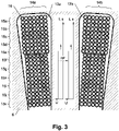
- FIG. 3 now shows the 2 marked area B in section, in this case with the stator coils 14a, 14b of the stator winding 8 arranged in the stator slots 13a, 13b.
- Each of the stator coils 14a, 14b has several windings 15a..15k, which are hatched differently for better differentiation.
- Each of the windings 15a .
- stator coils 14a, 14b In the 3 one half of the stator coils 14a, 14b can be seen in each case, specifically a right half of the stator coil 14a and a left half of the stator coil 14b are shown.
- the stator coils 14a, 14b have different winding directions, such as in FIGS Figures 4 and 5 is illustrated.
- the symbolically represented stator coil 14a is wound clockwise, the figure 5
- the symbolically shown stator coil 14b is counterclockwise. Accordingly, the coil wires are - roughly speaking - arranged along a left-hand or right-hand helix.
- FIGS Figures 4 and 5 For the sake of clarity, only four turns 15a..15d are shown symbolically, each with a different type of line.
- stator coil 14a shows the stator coil 14a and its arrangement in the stator slots 13 in the notation that is generally used in technical terms. Specifically, the stator coil 14a is illustrated in the shape of a hexagon, and the stator slots 13 are numbered with numbers. In addition, the coil input SE and the coil output SA are labeled.
- Fig.7 shows the pair of coils formed from the stator coils 14a and 14b in the notation that is generally used in technical terms. How from the 7 As can be seen, the stator coils 14a, 14b are electrically connected in parallel and occupy the stator slots 13 with the numbers "01", “02", “07” and "44". Consequently, in the 3 the stator slot 13a is shown with the number "02" and the stator slot 13b with the number "01”. Due to the parallel connection, the stator coils 14a, 14b are assigned to one phase L1 of several phases L1..L3 of the electrical machine 1 (see also 8 and 9 ).
- the 8 shows an exemplary winding scheme or circuit diagram of an eight-pole single-layer winding with 48 stator slots 13.
- the stator coils 14a, 14b are also provided with numbers.
- the 9 finally shows the winding scheme or circuit diagram 8 supplemented with the symbolic windings 15a..15k.
- a stator 5 for an electrical machine 1 which comprises an annular stator base body 7 with stator slots 13, 13a, 13b open towards the inside and stator coils 14a, 14b arranged in the stator slots 13, 13a, 13b, which have several phases L1 .. L3 of the electrical machine 1 are assigned. Adjacent stator coils 14a, 14b of the same phase L1 are wound in opposite directions and electrically connected in parallel. In particular, the radially inner terminals of the stator coils 14a, 14b and the radially outer terminals of the stator coils 14a, 14b of the same phase L1 are electrically connected to one another, respectively.
- a power supply connected to phase L1 therefore generates a current flow with a different winding sense in the stator coils 14a, 14b.
- all adjacent stator coils 14a, 14b of the same phase L1 or L2 or L3 are wound in opposite directions and electrically connected in parallel.
- a voltage-displacement diagram U/s or a voltage-time diagram U/t is shown for each stator winding 14a, 14b.
- the diagram shows that an edge of a voltage pulse propagates radially outwards from the coil input SE and the same electrical voltage is present at a specific radial position at a specific point in time t in both stator windings 14a, 14b.
- a potential difference ⁇ P at a The specific radial position is zero or almost zero, even in the case of fast transient processes such as can occur in modern inverters.
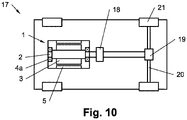
- the 10 finally shows the electric machine 1 installed in a vehicle 17.
- the vehicle 17 has at least two axles, at least one of which is driven.
- the electric motor 1 is connected to an optional gear 18 and a differential gear 19 .
- the semi-axles 20 of the rear axle connect to the differential gear 19 .
- the driven wheels 21 are mounted on the semi-axles 20 .
- the vehicle 17 is driven at least partially or temporarily by the electric machine 1. This means that the electric machine 1 can be used to drive the vehicle 17 alone or be provided, for example, in combination with an internal combustion engine (hybrid drive).
Landscapes
- Engineering & Computer Science (AREA)
- Power Engineering (AREA)
- Windings For Motors And Generators (AREA)
Abstract
Description
- Es wird ein Stator für eine elektrische Maschine angegeben, welcher einen ringförmigen Stator-Grundkörper mit mehreren aneinandergereihten Statorblechen und nach innen hin offenen Statornuten umfasst sowie in den Statornuten angeordnete Statorspulen einer Statorwicklung, welche mehreren Phasen der elektrischen Maschine zugeordnet sind. Weiterhin wird eine elektrische Maschine mit einem Rotor offenbart, der gegenüber einem Stator der oben genannten Art um die Rotationsachse des Rotors drehbar gelagert ist. Darüber hinaus wird eine Antriebsanordnung mit einer elektrischen Maschine der oben genannten Art und eine mit der Statorwicklung verbundene Stromversorgung angegeben, wobei die Stromversorgung dazu eingerichtet ist, elektrisch parallel geschaltete, benachbarte Statorspulen der gleichen Phase mit elektrischem Strom zu beaufschlagen. Schließlich wird ein Fahrzeug mit wenigstens zwei Achsen angegeben, von denen wenigstens eine angetrieben ist, wobei der besagte Antrieb zumindest teilweise oder zeitweise durch die elektrische Maschine der oben genannten Art erfolgt.
- Ein Stator, eine elektrische Maschine, eine Antriebsanordnung sowie ein Fahrzeug der oben angegeben Bauart sind aus dem Stand der Technik grundsätzlich bekannt. Insbesondere kann die Stromversorgung der Antriebsanordnung durch einen Wechselrichter gebildet sein, welcher die elektrische Maschine aus einer Batterie beziehungsweise aus einem Akkumulator mit elektrischer Energie versorgt. Immer schneller schaltende elektronische Schaltelemente (insbesondere Transistoren) führen zu Spannungsimpulsen mit sehr hoher Flankensteilheit. Durch die hohe Flankensteilheit kommen mitunter Wellenphänomene in den Statorspulen der Statorwicklung zum Tragen, und zwar in dem Sinne, dass eine sich entlang der Drähte benachbarter und parallel geschalteter Statorspulen fortpflanzende Flanke eines Spannungsimpulses zu einer gefährlichen Potentialdifferenz zwischen den Statorspulen führen kann. Dies ist insbesondere an den Stirnseiten des Stators beziehungsweise am Wickelkopf problematisch, da sich dort die besagten Drähte berühren können und die erwähnte Potentialdifferenz Schaden an den Statorspulen anrichten kann.
- Eine Aufgabe der Erfindung ist es daher, einen verbesserten Stator für eine elektrische Maschine, eine verbesserte elektrische Maschine, eine verbesserte Antriebsanordnung sowie ein verbessertes Fahrzeug mit einer solchen elektrischen Maschine anzugeben. Insbesondere soll eine Potentialdifferenz zwischen elektrisch parallel geschalteten und benachbarten Statorspulen der gleichen Phase auch bei schnellen Spannungsimpulsen vermieden werden.
- Die Aufgabe der Erfindung wird mit einem Stator der eingangs genannten Art gelöst, bei dem benachbarte Statorspulen der gleichen Phase gegensinnig gewickelt und elektrisch parallel geschaltet sind. Benachbarte Statorspulen der gleichen Phase weisen also unterschiedlichen Windungssinn auf, das heißt eine der benachbarten Statorspulen ist linksgängig, die andere rechtsgängig. Insbesondere sind zudem jeweils die radial innenliegenden Anschlüsse und jeweils die radial außenliegenden Anschlüsse der benachbarten Statorspulen der gleichen Phase elektrisch miteinander verbunden. Das heißt, der radial innenliegende Anschluss einer Statorspule ist dann mit dem radial innenliegenden Anschluss einer benachbarten Statorspule der gleichen Phase verbunden, und der radial außenliegende Anschluss einer Statorspule ist mit dem radial außenliegenden Anschluss der benachbarten Statorspule der gleichen Phase verbunden.
- Die Aufgabe der Erfindung wird auch mit einer elektrischen Maschine gelöst, welche einen Stator umfasst, sowie einen Rotor der oben genannten Art, der gegenüber dem Stator um die Rotationsachse des Rotors drehbar gelagert ist.
- Die Aufgabe der Erfindung wird darüber hinaus mit einer Antriebsanordnung gelöst, welche eine elektrische Maschine der oben genannten Art und eine mit der Statorwicklung verbundene Stromversorgung umfasst, wobei die Stromversorgung dazu eingerichtet ist, in den gegensinnig gewickelten und elektrisch parallel geschalteten benachbarten Statorspulen der gleichen Phase einen Stromfluss mit unterschiedlichem Windungssinn (das heißt linksgängig und rechtsgängig) zu verursachen.
- Schließlich wird die Aufgabe auch durch ein Fahrzeug mit wenigstens zwei Achsen gelöst, von denen wenigstens eine angetrieben ist, wobei der besagte Antrieb zumindest teilweise oder zeitweise durch die oben genannte elektrische Maschine erfolgt.
- Mit Hilfe der vorgeschlagenen Maßnahmen können die eingangs genannten Nachteile überwunden werden. Insbesondere nimmt die Potentialdifferenz zwischen benachbarten Windungen der Statorspulen auch bei Spannungsimpulsen mit sehr hoher Flankensteilheit keine nennenswerten Werte an. Der Grund ist, dass sich diese Spannungsimpulse in benachbarten Statorspulen in dieselbe Richtung, also radial nach außen oder radial nach innen, fortpflanzen und sich eine Flanke in beiden Statorspulen zur selben Zeit an derselben radialen Position befindet. Das Risiko eines elektrischen Überschlags zwischen den Statorspulen, insbesondere im Bereich an den Stirnseiten des Stators beziehungsweise am Wickelkopf, ist daher gering. Eine Potentialdifferenz zwischen elektrisch parallel geschalteten und benachbarten Statorspulen der gleichen Phase ist an einer bestimmten Radialposition ist somit auch bei schnellen transienten Vorgängen, wie sie in modernen Wechselrichtern vorkommen können, Null oder annähernd Null.
- Elektrische Leiter, welche von benachbarten Statorspulen der gleichen Phase umfasst sind, sind jeweils im Wesentlichen schraubenlinienförmig ausgebildet und erstrecken sich ausgehend von einem Verbindungspukt der Parallelschaltung bezogen auf eine Drehachse des Stator-Grundkörpers radial in die gleiche Richtung. Mit anderen Worten sind elektrische Leiter, welche von benachbarten Statorspulen der gleichen Phase umfasst sind, jeweils im Wesentlichen schraubenlinienförmig ausgebildet, und eine auf eine Drehachse des Stator-Grundkörpers bezogene Radialkomponente einer Längserstreckung der elektrischen Leiter ist ausgehend von einem Verbindungspukt der Parallelschaltung gleich ausgerichtet.
- Radial innenliegende Anschlüsse und radial außenliegende Anschlüsse der benachbarten Statorspulen der gleichen Phase können jeweils elektrisch miteinander verbunden, insbesondere direkt miteinander verbunden sein. Die Anschlüsse der benachbarten Statorspulen der gleichen Phase können einen gemeinsamen oder getrennte Sternpunkte aufweisen.
- Die obigen Ausgestaltungen und Weiterbildungen der Erfindung lassen sich auf beliebige Art und Weise kombinieren.
- Die vorliegende Erfindung wird nachfolgend anhand des in der schematischen Figur der Zeichnung angegebenen Ausführungsbeispiels näher erläutert. Es zeigt dabei:
- Figur 1
- eine schematisch im Halbschnitt dargestellte, beispielhafte elektrische Maschine;
- Figur 2
- den Stator-Grundkörper der elektrischen Maschine aus
Fig. 1 in Vorderansicht; - Figur 3
- einen Schnitt durch den Stator in Detailansicht;
- Figur 4
- eine schematische Darstellung einer im Uhrzeigersinn gewickelten Statorspule;
- Figur 5
- eine schematische Darstellung einer im Gegenuhrzeigersinn gewickelten Statorspule;
- Figur 6
- die Statorspule aus
Fig. 4 in technisch gebräuchlicher Darstellung; - Figur 7
- die Statorspulen aus
Fig. 4 und 5 in technisch gebräuchlicher Darstellung; - Figur 8
- ein Schalbild eines beispielhaften Stators einer elektrischen Maschine;
- Figur 9
- das Schaltbild aus
Fig. 8 ergänzt mit Symboldarstellungen der Statorspulen und - Figur 10
- eine elektrische Maschine mit einem Stator der vorgeschlagenen Art, welche in ein Fahrzeug eingebaut ist.
- Einführend wird festgehalten, dass gleiche Teile in den unterschiedlich Ausführungsformen mit gleichen Bezugszeichen beziehungsweise gleichen Bauteilbezeichnungen versehen werden, gegebenenfalls mit unterschiedlichen Indizes. Die in der Beschreibung enthaltene Offenbarungen eines Bauteils kann sinngemäß ein anderes Bauteil mit gleichem Bezugszeichen beziehungsweise gleicher Bauteilbezeichnung übertragen werden. Auch sind die in der Beschreibung gewählten Lageangaben, wie zum Beispiel "oben", "unten", "hinten", "vorne", "seitlich" und so weiter auf die unmittelbar beschriebene sowie dargestellte Figur bezogen und bei einer Lageänderung sinngemäß auf die neue Lage zu übertragen.
-
Fig. 1 zeigt einen Halbschnitt durch eine schematisch dargestellte elektrische Maschine 1. Die elektrische Maschine 1 umfasst, eine Welle 2 mit einem darauf sitzenden Rotor 3, wobei die Welle 2 mit Hilfe von (Wälz)lagern 4a, 4b um eine Drehachse A gegenüber einem Stator 5 drehbar gelagert ist. Der Stator 5 umfasst in diesem Beispiel mehrere Statorbleche 6, welche ein Statorblechpaket oder einen Stator-Grundkörper 7 bilden, sowie eine in diesem angeordnete Statorwicklung 8. Konkret sitzt das erste Lager 4a in einem vorderen Lagerschild 9 und das zweite Lager 4b in einem hinteren Lagerschild 10. Weiterhin umfasst die elektrische Maschine 1 ein (mittleres) Gehäuseteil 11, welches das vordere Lagerschild 9 und das hintere Lagerschild 10 verbindet und weiterhin den Stator-Grundkörper 7 aufnimmt. Das vordere Lagerschild 9, das hintere Lagerschild 10 und das Gehäuseteil 11 bilden in diesem Beispiel somit das Gehäuse 12 der elektrische Maschine 1. -
Fig. 2 zeigt den Stator-Grundkörper 7 nun in Vorderansicht, konkret ohne Statorwicklung 8. Gut erkennbar sind die radial nach innen offenen Statornuten 13, welche die Statorwicklung 8 aufnehmen, welche mehrere Statorspulen umfasst. In derFig. 2 ist weiterhin ein Bereich B gekennzeichnet, der in derFig. 3 in vergrößerter Form dargestellt ist. Die Statornuten 13 können insbesondere in axialer Richtung oder schraubenlinienförmig verlaufen -
Fig. 3 zeigt nun denFig. 2 gekennzeichneten Bereich B im Schnitt, in diesem Fall mit den in den Statornuten 13a, 13b angeordneten Statorspulen 14a, 14b der Statorwicklung 8. Jede der Statorspulen 14a, 14b weist mehrere Windungen 15a..15k auf, die zur besseren Unterscheidung unterschiedlich schraffiert sind. Jede der Windungen 15a..15k besteht wiederum aus mehreren Spulendrähten 16, im konkreten Fall aus zehn Spulendrähten 16. Es könnte aber auch eine andere Anzahl von Windungen 15a..15k und Spulendrähten 16 vorgesehen sein. - In der
Fig. 3 ist jeweils eine Hälfte der Statorspulen 14a, 14b zu sehen, konkret ist eine rechte Hälfte der Statorspule 14a und eine linke Hälfte der Statorspule 14b dargestellt. Die Statorspulen 14a, 14b weisen unterschiedlichen Wicklungssinn auf, so wie das in denFig. 4 und 5 illustriert ist. Die inFig. 4 symbolisch dargestellte Statorspule 14a ist im Uhrzeigersinn gewunden, die inFig. 5 symbolisch dargestellte Statorspule 14b ist im Gegenuhrzeigersinn. Demzufolge sind die Spulendrähte - grob gesprochen - entlang einer linksgängigen oder rechtsgängigen Schraubenlinie angeordnet. In denFig. 4 und 5 sind der besseren Übersicht halber lediglich vier Windungen 15a..15d symbolisch dargestellt, jeweils mit unterschiedlicher Strichart. -
Fig. 6 zeigt die Statorspule 14a und ihre Anordnung in den Statornuten 13 in technisch allgemein gebräuchlicher Notation. Konkret ist die Statorspule 14a in Form eines Sechsecks dargestellt, und die Statornuten 13 sind mit Zahlen nummeriert. Zudem ist der Spuleneingang SE und der Spulenausgang SA bezeichnet. -
Fig.7 zeigt das aus den Statorspulen 14a und 14b gebildete Spulenpaar in technisch allgemein gebräuchlicher Notation. Wie aus derFig. 7 ersichtlich ist, sind die Statorspulen 14a, 14b elektrisch parallel geschaltet und belegen die Statornuten 13 mit den Nummern "01", "02", "07" und "44". Demzufolge sind in derFig. 3 die Statornut 13a mit der Nummer "02" und die Statornut 13b mit der Nummer "01" dargestellt. Durch die Parallelschaltung sind die Statorspulen 14a, 14b einer Phase L1 von mehreren Phasen L1..L3 der elektrischen Maschine 1 zugeordnet (siehe auchFig. 8 und9 ). - Die
Fig. 8 zeigt ein beispielhaftes Wicklungsschema beziehungsweise Schaltbild einer achtpoligen Einschichtwicklung mit 48 Statornuten 13. Die Statorspulen 14a, 14b sind dabei ebenfalls mit Nummern versehen. DieFig. 9 zeigt schließlich das Wicklungsschema beziehungsweise Schaltbild ausFig. 8 ergänzt mit dem symbolischen Windungen 15a..15k. - Es wird somit ein Stator 5 für eine elektrische Maschine 1 offenbart, welcher einen ringförmigen Stator-Grundkörper 7 mit nach innen hin offenen Statornuten 13, 13a, 13b umfasst sowie in den Statornuten 13, 13a, 13b angeordnete Statorspulen 14a, 14b, welche mehreren Phasen L1..L3 der elektrischen Maschine 1 zugeordnet sind. Benachbarte Statorspulen 14a, 14b der gleichen Phase L1 sind dabei gegensinnig gewickelt und elektrisch parallel geschaltet. Insbesondere sind die radial innenliegenden Anschlüsse der Statorspulen 14a, 14b und die radial außenliegenden Anschlüsse der Statorspulen 14a, 14b der gleichen Phase L1 jeweils elektrisch miteinander verbunden. Eine mit der Phase L1 verbundene Stromversorgung erzeugt in den Statorspulen 14a, 14b daher einen Stromfluss mit unterschiedlichem Windungssinn. Insbesondere sind, so wie das hier der Fall ist, alle benachbarten Statorspulen 14a, 14b der gleichen Phase L1 oder L2 oder L3 gegensinnig gewickelt und elektrisch parallel geschaltet.
- Daraus resultiert der Vorteil, dass die Potentialdifferenz zwischen benachbarten Windungen 15a..15k der Statorspulen 14a, 14b auch bei Spannungsimpulsen mit sehr hoher Flankensteilheit keine nennenswerten Werte annimmt. Der Grund ist, dass sich diese Spannungsimpulse in benachbarten Statorspulen 14a, 14b in dieselbe Richtung, also radial nach außen oder radial nach innen, fortpflanzen und sich eine Flanke in beiden Statorspulen 14a, 14b zur selben Zeit an derselben radialen Position befindet. Das Risiko eines elektrischen Überschlags zwischen den Statorspulen 14a, 14b, insbesondere im Bereich an den Stirnseiten des Stators 5 beziehungsweise am Wickelkopf, ist daher gering.
- In der
Fig. 3 ist für jede Statorwicklung 14a, 14b ein Spannungs-Weg-Diagramm U/s beziehungsweise Spannungs-Zeit-Diagramm U/t dargestellt. In dem Diagramm ist erkennbar, dass sich eine Flanke eines Spannungsimpulses vom Spuleneingang SE radial nach außen fortpflanzt und an einer bestimmten Radialposition zu einem bestimmten Zeitpunkt t in beiden Statorwicklung 14a, 14b dieselbe elektrische Spannung vorliegt. Eine Potentialdifferenz ΔP an einer bestimmten Radialposition ist auch bei schnellen transienten Vorgängen, wie sie in modernen Wechselrichtern vorkommen können, Null oder annähernd Null. - Die
Fig. 10 zeigt schließlich die in ein Fahrzeug 17 eingebaute elektrische Maschine 1. Das Fahrzeug 17 weist wenigstens zwei Achsen auf, von denen wenigstens eine angetrieben ist. Konkret ist der Elektromotor 1 mit einem optionalen Getriebe 18 und einem Differentialgetriebe 19 verbunden. An das Differentialgetriebe 19 schließen die Halbachsen 20 der Hinterachse an. An den Halbachsen 20 sind schließlich die angetriebenen Räder 21 montiert. Der Antrieb des Fahrzeugs 17 erfolgt zumindest teilweise oder zeitweise durch die elektrische Maschine 1. Das heißt, die elektrische Maschine 1 kann zum alleinigen Antrieb des Fahrzeugs 17 dienen oder zum Beispiel im Verbund mit einer Verbrennungskraftmaschine vorgesehen sein (Hybridantrieb). - Abschließend wird festgehalten, dass der Schutzbereich durch die Patentansprüche bestimmt ist. Die Beschreibung und die Zeichnungen sind jedoch zur Auslegung der Ansprüche heranzuziehen. Die in den Figuren enthaltenen Merkmale können beliebig ausgetauscht und miteinander kombiniert werden. Insbesondere wird auch festgehalten, dass die dargestellten Vorrichtungen in der Realität auch mehr oder auch weniger Bestandteile als dargestellt umfassen können. Teilweise können die dargestellten Vorrichtungen beziehungsweise deren Bestandteile auch unmaßstäblich und/oder vergrößert und/oder verkleinert dargestellt sein.
Claims (7)
- Stator (5) für eine elektrische Maschine (1), umfassend einen ringförmigen Stator-Grundkörper (7) mit mehreren Statorblechen (6) und nach innen hin offenen Statornuten (13, 13a, 13b) sowie in den Statornuten (13, 13a, 13b) angeordnete Statorspulen (14a, 14b) einer Statorwicklung (8), welche mehreren Phasen (L1..L3) der elektrische Maschine (1) zugeordnet sind, wobei benachbarte Statorspulen (14a, 14b) der gleichen Phase (L1..L3) gegensinnig gewickelt und elektrisch parallel geschaltet sind.
- Stator (5) nach Anspruch 1, dadurch gekennzeichnet, dass radial innenliegende Anschlüsse und radial außenliegende Anschlüsse der benachbarten Statorspulen (14a, 14b) der gleichen Phase (L1..L3) jeweils elektrisch miteinander verbunden sind, insbesondere direkt miteinander verbunden sind.
- Stator (5) nach Anspruch 2, dadurch gekennzeichnet, dass die Anschlüsse der benachbarten Statorspulen (14a, 14b) der gleichen Phase (L1..L3) einen gemeinsamen oder getrennte Sternpunkte aufweisen.
- Stator (5) nach einem Ansprüche 1 bis 3, dadurch gekennzeichnet, dass elektrische Leiter (16), welche von benachbarten Statorspulen (14a, 14b) der gleichen Phase (L1 ..L3) umfasst sind, jeweils im Wesentlichen schraubenlinienförmig ausgebildet sind und sich ausgehend von einem Verbindungspukt der Parallelschaltung bezogen auf eine Drehachse (A) des Stator-Grundkörpers (7) radial in die gleiche Richtung erstrecken.
- Elektrische Maschine (1) mit einem Rotor (3), der gegenüber einem Stator (5) um die Rotationsachse (A) des Rotors (3) drehbar gelagert ist, dadurch gekennzeichnet dass der Stator (5) nach einem der Ansprüche 1 bis 4 ausgebildet ist.
- Antriebsanordnung umfassend eine elektrische Maschine (1) nach Anspruch 5 und eine mit den Statorwicklung (8) verbundene Stromversorgung, dadurch gekennzeichnet, dass die Stromversorgung dazu eingerichtet ist, in den gegensinnig gewickelten und elektrisch parallel geschalteten benachbarten Statorspulen (14a, 14b) der gleichen Phase (L1..L3) einen Stromfluss mit unterschiedlichem Windungssinn zu verursachen.
- Fahrzeug (17) mit wenigstens zwei Achsen, von denen wenigstens eine angetrieben ist, dadurch gekennzeichnet dass der besagte Antrieb zumindest teilweise oder zeitweise durch die elektrische Maschine (1) nach Anspruch 6 erfolgt.
Applications Claiming Priority (1)
| Application Number | Priority Date | Filing Date | Title |
|---|---|---|---|
| DE102020126704.5A DE102020126704A1 (de) | 2020-10-12 | 2020-10-12 | Stator für eine elektrische Maschine mit verbessertem Schutz gegen Potentialdifferenzen zwischen benachbarten Statorspulen |
Publications (2)
| Publication Number | Publication Date |
|---|---|
| EP3982517A1 true EP3982517A1 (de) | 2022-04-13 |
| EP3982517B1 EP3982517B1 (de) | 2025-09-17 |
Family
ID=78086264
Family Applications (1)
| Application Number | Title | Priority Date | Filing Date |
|---|---|---|---|
| EP21201557.2A Active EP3982517B1 (de) | 2020-10-12 | 2021-10-08 | Stator für eine elektrische maschine mit verbessertem schutz gegen potentialdifferenzen zwischen benachbarten statorspulen |
Country Status (4)
| Country | Link |
|---|---|
| US (1) | US20220115921A1 (de) |
| EP (1) | EP3982517B1 (de) |
| CN (1) | CN114337007A (de) |
| DE (1) | DE102020126704A1 (de) |
Families Citing this family (1)
| Publication number | Priority date | Publication date | Assignee | Title |
|---|---|---|---|---|
| EP3614533A1 (de) * | 2018-08-21 | 2020-02-26 | Siemens Gamesa Renewable Energy A/S | Konzentrierte wicklungsanordnung für einen stator einer elektrischen wechselstrommaschine |
Citations (6)
| Publication number | Priority date | Publication date | Assignee | Title |
|---|---|---|---|---|
| DE1488661A1 (de) * | 1965-03-31 | 1969-05-29 | Siemens Ag | Wechselstromschleifenwicklung fuer elektrische Maschinen |
| US5898251A (en) * | 1995-08-18 | 1999-04-27 | Kabushiki Kaisha Toshiba | Method of making armature winding of double-layer concentric-wound or lap-winding type for dynamoelectric machine |
| DE10331841A1 (de) * | 2002-07-15 | 2004-02-26 | Denso Corp., Kariya | Rotierende elektrische Maschine mit einer sequentielle Segmente verbindenden Statorspule |
| US20080238240A1 (en) * | 2007-03-29 | 2008-10-02 | Kazuhiko Takahashi | Rotary electric machine |
| WO2014184951A1 (ja) * | 2013-05-17 | 2014-11-20 | 三菱電機株式会社 | 回転電機の固定子 |
| DE102017210445A1 (de) * | 2017-06-21 | 2018-12-27 | Robert Bosch Gmbh | Stator für eine elektrische Maschine |
Family Cites Families (1)
| Publication number | Priority date | Publication date | Assignee | Title |
|---|---|---|---|---|
| JP5497613B2 (ja) * | 2010-10-27 | 2014-05-21 | 日立オートモティブシステムズ株式会社 | 回転電機 |
-
2020
- 2020-10-12 DE DE102020126704.5A patent/DE102020126704A1/de active Pending
-
2021
- 2021-10-08 EP EP21201557.2A patent/EP3982517B1/de active Active
- 2021-10-11 CN CN202111180625.7A patent/CN114337007A/zh active Pending
- 2021-10-12 US US17/498,962 patent/US20220115921A1/en not_active Abandoned
Patent Citations (6)
| Publication number | Priority date | Publication date | Assignee | Title |
|---|---|---|---|---|
| DE1488661A1 (de) * | 1965-03-31 | 1969-05-29 | Siemens Ag | Wechselstromschleifenwicklung fuer elektrische Maschinen |
| US5898251A (en) * | 1995-08-18 | 1999-04-27 | Kabushiki Kaisha Toshiba | Method of making armature winding of double-layer concentric-wound or lap-winding type for dynamoelectric machine |
| DE10331841A1 (de) * | 2002-07-15 | 2004-02-26 | Denso Corp., Kariya | Rotierende elektrische Maschine mit einer sequentielle Segmente verbindenden Statorspule |
| US20080238240A1 (en) * | 2007-03-29 | 2008-10-02 | Kazuhiko Takahashi | Rotary electric machine |
| WO2014184951A1 (ja) * | 2013-05-17 | 2014-11-20 | 三菱電機株式会社 | 回転電機の固定子 |
| DE102017210445A1 (de) * | 2017-06-21 | 2018-12-27 | Robert Bosch Gmbh | Stator für eine elektrische Maschine |
Also Published As
| Publication number | Publication date |
|---|---|
| DE102020126704A1 (de) | 2022-04-14 |
| EP3982517B1 (de) | 2025-09-17 |
| CN114337007A (zh) | 2022-04-12 |
| US20220115921A1 (en) | 2022-04-14 |
Similar Documents
| Publication | Publication Date | Title |
|---|---|---|
| DE112018000146T5 (de) | Elektrische Maschine mit einem Stator, der mehrere Anschlussdrähte hat, die von einer gemeinsamen Wicklungsschicht ausgehen | |
| WO2010040785A2 (de) | Elektrische maschine | |
| WO2009000578A2 (de) | Synchronmotor mit 12 statorzähnen und 10 rotorpolen | |
| EP2115857B1 (de) | 18/8-synchronmotor | |
| EP2427951B1 (de) | Elektrische synchronmaschine | |
| EP3479458B1 (de) | Rotor, verfahren zum herstellen eines rotors, reluktanzmaschine und arbeitsmaschine | |
| DE102021133267A1 (de) | Elektrischer Antrieb eines Fahrzeuges | |
| DE102021204303A1 (de) | Elektrische Maschine und Stator hierfür mit verbesserter Anordnung von Leitern einer Statorwicklung | |
| WO2019072471A1 (de) | Stator für eine elektrische maschine | |
| DE112018000190T5 (de) | Elektrische Maschine mit einem Stator, der mehrlagige Endschlaufen hat | |
| EP2340601A2 (de) | Rotierende elektrische maschine | |
| EP3982517B1 (de) | Stator für eine elektrische maschine mit verbessertem schutz gegen potentialdifferenzen zwischen benachbarten statorspulen | |
| WO2024126579A1 (de) | Stator für eine elektrische maschine | |
| DE102011084716A1 (de) | Elektrische Maschine | |
| DE10129152B4 (de) | Antriebsbaugruppe und Antriebsvorrichtung für Fahrzeuge | |
| DE102020213647A1 (de) | Stator für eine elektrische Maschine und elektrische Maschine | |
| DE102020203945A1 (de) | Statorwicklungssystem mit serieller Spulenwicklung | |
| DE102019108047A1 (de) | Rotor für einen Permanentmagnet-Synchronmotor, Permanentmagnet-Synchronmotor und Fahrzeug | |
| DE112021003763T5 (de) | Drehende elektrische maschine | |
| DE102023208847B4 (de) | Wicklung, Komponente für eine elektrische Maschine, elektrische Maschine und Kraftfahrzeug und Verfahren zum Herstellen einer Wicklung | |
| DE102020201547A1 (de) | Stator einer elektrischen Maschine | |
| DE102024128795A1 (de) | Elektrische Axialflussmaschine mit Rotorfilter | |
| EP4010969B1 (de) | Verkoppeltes maschinensystem | |
| WO2023078740A1 (de) | Elektrischer antrieb mit einer elektrischen maschine mit sternpunktumschaltung | |
| DE102023203356A1 (de) | Antriebsachse für ein Elektrofahrzeug |
Legal Events
| Date | Code | Title | Description |
|---|---|---|---|
| PUAI | Public reference made under article 153(3) epc to a published international application that has entered the european phase |
Free format text: ORIGINAL CODE: 0009012 |
|
| STAA | Information on the status of an ep patent application or granted ep patent |
Free format text: STATUS: THE APPLICATION HAS BEEN PUBLISHED |
|
| AK | Designated contracting states |
Kind code of ref document: A1 Designated state(s): AL AT BE BG CH CY CZ DE DK EE ES FI FR GB GR HR HU IE IS IT LI LT LU LV MC MK MT NL NO PL PT RO RS SE SI SK SM TR |
|
| RAP3 | Party data changed (applicant data changed or rights of an application transferred) |
Owner name: VALEO EAUTOMOTIVE GERMANY GMBH |
|
| STAA | Information on the status of an ep patent application or granted ep patent |
Free format text: STATUS: REQUEST FOR EXAMINATION WAS MADE |
|
| 17P | Request for examination filed |
Effective date: 20221012 |
|
| RBV | Designated contracting states (corrected) |
Designated state(s): AL AT BE BG CH CY CZ DE DK EE ES FI FR GB GR HR HU IE IS IT LI LT LU LV MC MK MT NL NO PL PT RO RS SE SI SK SM TR |
|
| P01 | Opt-out of the competence of the unified patent court (upc) registered |
Effective date: 20230528 |
|
| GRAP | Despatch of communication of intention to grant a patent |
Free format text: ORIGINAL CODE: EPIDOSNIGR1 |
|
| STAA | Information on the status of an ep patent application or granted ep patent |
Free format text: STATUS: GRANT OF PATENT IS INTENDED |
|
| RIC1 | Information provided on ipc code assigned before grant |
Ipc: H02K 3/12 20060101ALN20250408BHEP Ipc: H02K 3/28 20060101AFI20250408BHEP |
|
| INTG | Intention to grant announced |
Effective date: 20250424 |
|
| GRAS | Grant fee paid |
Free format text: ORIGINAL CODE: EPIDOSNIGR3 |
|
| GRAA | (expected) grant |
Free format text: ORIGINAL CODE: 0009210 |
|
| STAA | Information on the status of an ep patent application or granted ep patent |
Free format text: STATUS: THE PATENT HAS BEEN GRANTED |
|
| AK | Designated contracting states |
Kind code of ref document: B1 Designated state(s): AL AT BE BG CH CY CZ DE DK EE ES FI FR GB GR HR HU IE IS IT LI LT LU LV MC MK MT NL NO PL PT RO RS SE SI SK SM TR |
|
| REG | Reference to a national code |
Ref country code: GB Ref legal event code: FG4D Free format text: NOT ENGLISH |
|
| RIN1 | Information on inventor provided before grant (corrected) |
Inventor name: MUELLER, MICHAEL Inventor name: MENZ, MICHAEL |
|
| REG | Reference to a national code |
Ref country code: CH Ref legal event code: EP |
|
| REG | Reference to a national code |
Ref country code: IE Ref legal event code: FG4D Free format text: LANGUAGE OF EP DOCUMENT: GERMAN |
|
| REG | Reference to a national code |
Ref country code: DE Ref legal event code: R096 Ref document number: 502021008706 Country of ref document: DE |
|
| PGFP | Annual fee paid to national office [announced via postgrant information from national office to epo] |
Ref country code: DE Payment date: 20251015 Year of fee payment: 5 |
|
| PG25 | Lapsed in a contracting state [announced via postgrant information from national office to epo] |
Ref country code: NO Free format text: LAPSE BECAUSE OF FAILURE TO SUBMIT A TRANSLATION OF THE DESCRIPTION OR TO PAY THE FEE WITHIN THE PRESCRIBED TIME-LIMIT Effective date: 20251217 |
|
| REG | Reference to a national code |
Ref country code: LT Ref legal event code: MG9D |
|
| PGFP | Annual fee paid to national office [announced via postgrant information from national office to epo] |
Ref country code: AT Payment date: 20260113 Year of fee payment: 5 |
|
| PG25 | Lapsed in a contracting state [announced via postgrant information from national office to epo] |
Ref country code: FI Free format text: LAPSE BECAUSE OF FAILURE TO SUBMIT A TRANSLATION OF THE DESCRIPTION OR TO PAY THE FEE WITHIN THE PRESCRIBED TIME-LIMIT Effective date: 20250917 |
|
| PG25 | Lapsed in a contracting state [announced via postgrant information from national office to epo] |
Ref country code: HR Free format text: LAPSE BECAUSE OF FAILURE TO SUBMIT A TRANSLATION OF THE DESCRIPTION OR TO PAY THE FEE WITHIN THE PRESCRIBED TIME-LIMIT Effective date: 20250917 |
|
| PGFP | Annual fee paid to national office [announced via postgrant information from national office to epo] |
Ref country code: FR Payment date: 20251027 Year of fee payment: 5 |
|
| PG25 | Lapsed in a contracting state [announced via postgrant information from national office to epo] |
Ref country code: GR Free format text: LAPSE BECAUSE OF FAILURE TO SUBMIT A TRANSLATION OF THE DESCRIPTION OR TO PAY THE FEE WITHIN THE PRESCRIBED TIME-LIMIT Effective date: 20251218 |
|
| PG25 | Lapsed in a contracting state [announced via postgrant information from national office to epo] |
Ref country code: SE Free format text: LAPSE BECAUSE OF FAILURE TO SUBMIT A TRANSLATION OF THE DESCRIPTION OR TO PAY THE FEE WITHIN THE PRESCRIBED TIME-LIMIT Effective date: 20250917 |
|
| REG | Reference to a national code |
Ref country code: NL Ref legal event code: MP Effective date: 20250917 |
|
| PG25 | Lapsed in a contracting state [announced via postgrant information from national office to epo] |
Ref country code: LV Free format text: LAPSE BECAUSE OF FAILURE TO SUBMIT A TRANSLATION OF THE DESCRIPTION OR TO PAY THE FEE WITHIN THE PRESCRIBED TIME-LIMIT Effective date: 20250917 |
|
| PG25 | Lapsed in a contracting state [announced via postgrant information from national office to epo] |
Ref country code: BG Free format text: LAPSE BECAUSE OF FAILURE TO SUBMIT A TRANSLATION OF THE DESCRIPTION OR TO PAY THE FEE WITHIN THE PRESCRIBED TIME-LIMIT Effective date: 20250917 |
|
| PG25 | Lapsed in a contracting state [announced via postgrant information from national office to epo] |
Ref country code: RS Free format text: LAPSE BECAUSE OF FAILURE TO SUBMIT A TRANSLATION OF THE DESCRIPTION OR TO PAY THE FEE WITHIN THE PRESCRIBED TIME-LIMIT Effective date: 20251217 |
|
| PG25 | Lapsed in a contracting state [announced via postgrant information from national office to epo] |
Ref country code: NL Free format text: LAPSE BECAUSE OF FAILURE TO SUBMIT A TRANSLATION OF THE DESCRIPTION OR TO PAY THE FEE WITHIN THE PRESCRIBED TIME-LIMIT Effective date: 20250917 |
|
| PG25 | Lapsed in a contracting state [announced via postgrant information from national office to epo] |
Ref country code: SM Free format text: LAPSE BECAUSE OF FAILURE TO SUBMIT A TRANSLATION OF THE DESCRIPTION OR TO PAY THE FEE WITHIN THE PRESCRIBED TIME-LIMIT Effective date: 20250917 |
|
| PG25 | Lapsed in a contracting state [announced via postgrant information from national office to epo] |
Ref country code: ES Free format text: LAPSE BECAUSE OF FAILURE TO SUBMIT A TRANSLATION OF THE DESCRIPTION OR TO PAY THE FEE WITHIN THE PRESCRIBED TIME-LIMIT Effective date: 20250917 |
|
| PG25 | Lapsed in a contracting state [announced via postgrant information from national office to epo] |
Ref country code: IT Free format text: LAPSE BECAUSE OF FAILURE TO SUBMIT A TRANSLATION OF THE DESCRIPTION OR TO PAY THE FEE WITHIN THE PRESCRIBED TIME-LIMIT Effective date: 20250917 Ref country code: RO Free format text: LAPSE BECAUSE OF FAILURE TO SUBMIT A TRANSLATION OF THE DESCRIPTION OR TO PAY THE FEE WITHIN THE PRESCRIBED TIME-LIMIT Effective date: 20250917 |
|
| PG25 | Lapsed in a contracting state [announced via postgrant information from national office to epo] |
Ref country code: IS Free format text: LAPSE BECAUSE OF FAILURE TO SUBMIT A TRANSLATION OF THE DESCRIPTION OR TO PAY THE FEE WITHIN THE PRESCRIBED TIME-LIMIT Effective date: 20260117 |
|
| PG25 | Lapsed in a contracting state [announced via postgrant information from national office to epo] |
Ref country code: CZ Free format text: LAPSE BECAUSE OF FAILURE TO SUBMIT A TRANSLATION OF THE DESCRIPTION OR TO PAY THE FEE WITHIN THE PRESCRIBED TIME-LIMIT Effective date: 20250917 Ref country code: PT Free format text: LAPSE BECAUSE OF FAILURE TO SUBMIT A TRANSLATION OF THE DESCRIPTION OR TO PAY THE FEE WITHIN THE PRESCRIBED TIME-LIMIT Effective date: 20260119 |
|
| PG25 | Lapsed in a contracting state [announced via postgrant information from national office to epo] |
Ref country code: PL Free format text: LAPSE BECAUSE OF FAILURE TO SUBMIT A TRANSLATION OF THE DESCRIPTION OR TO PAY THE FEE WITHIN THE PRESCRIBED TIME-LIMIT Effective date: 20250917 |
|
| PG25 | Lapsed in a contracting state [announced via postgrant information from national office to epo] |
Ref country code: SK Free format text: LAPSE BECAUSE OF FAILURE TO SUBMIT A TRANSLATION OF THE DESCRIPTION OR TO PAY THE FEE WITHIN THE PRESCRIBED TIME-LIMIT Effective date: 20250917 Ref country code: EE Free format text: LAPSE BECAUSE OF FAILURE TO SUBMIT A TRANSLATION OF THE DESCRIPTION OR TO PAY THE FEE WITHIN THE PRESCRIBED TIME-LIMIT Effective date: 20250917 |