EP3982193A1 - Device for detecting liquid crystal mura in polarizing plate, and method for detecting liquid crystal mura in polarizing plate - Google Patents
Device for detecting liquid crystal mura in polarizing plate, and method for detecting liquid crystal mura in polarizing plate Download PDFInfo
- Publication number
- EP3982193A1 EP3982193A1 EP20818594.2A EP20818594A EP3982193A1 EP 3982193 A1 EP3982193 A1 EP 3982193A1 EP 20818594 A EP20818594 A EP 20818594A EP 3982193 A1 EP3982193 A1 EP 3982193A1
- Authority
- EP
- European Patent Office
- Prior art keywords
- liquid crystal
- polarization plate
- polarization
- light
- inspection device
- Prior art date
- Legal status (The legal status is an assumption and is not a legal conclusion. Google has not performed a legal analysis and makes no representation as to the accuracy of the status listed.)
- Granted
Links
Images
Classifications
-
- G—PHYSICS
- G01—MEASURING; TESTING
- G01N—INVESTIGATING OR ANALYSING MATERIALS BY DETERMINING THEIR CHEMICAL OR PHYSICAL PROPERTIES
- G01N21/00—Investigating or analysing materials by the use of optical means, i.e. using sub-millimetre waves, infrared, visible or ultraviolet light
- G01N21/84—Systems specially adapted for particular applications
- G01N21/88—Investigating the presence of flaws or contamination
- G01N21/94—Investigating contamination, e.g. dust
-
- G—PHYSICS
- G01—MEASURING; TESTING
- G01N—INVESTIGATING OR ANALYSING MATERIALS BY DETERMINING THEIR CHEMICAL OR PHYSICAL PROPERTIES
- G01N21/00—Investigating or analysing materials by the use of optical means, i.e. using sub-millimetre waves, infrared, visible or ultraviolet light
- G01N21/84—Systems specially adapted for particular applications
- G01N21/88—Investigating the presence of flaws or contamination
- G01N21/95—Investigating the presence of flaws or contamination characterised by the material or shape of the object to be examined
-
- G—PHYSICS
- G02—OPTICS
- G02F—OPTICAL DEVICES OR ARRANGEMENTS FOR THE CONTROL OF LIGHT BY MODIFICATION OF THE OPTICAL PROPERTIES OF THE MEDIA OF THE ELEMENTS INVOLVED THEREIN; NON-LINEAR OPTICS; FREQUENCY-CHANGING OF LIGHT; OPTICAL LOGIC ELEMENTS; OPTICAL ANALOGUE/DIGITAL CONVERTERS
- G02F1/00—Devices or arrangements for the control of the intensity, colour, phase, polarisation or direction of light arriving from an independent light source, e.g. switching, gating or modulating; Non-linear optics
- G02F1/01—Devices or arrangements for the control of the intensity, colour, phase, polarisation or direction of light arriving from an independent light source, e.g. switching, gating or modulating; Non-linear optics for the control of the intensity, phase, polarisation or colour
- G02F1/13—Devices or arrangements for the control of the intensity, colour, phase, polarisation or direction of light arriving from an independent light source, e.g. switching, gating or modulating; Non-linear optics for the control of the intensity, phase, polarisation or colour based on liquid crystals, e.g. single liquid crystal display cells
- G02F1/1306—Details
- G02F1/1309—Repairing; Testing
-
- G—PHYSICS
- G01—MEASURING; TESTING
- G01N—INVESTIGATING OR ANALYSING MATERIALS BY DETERMINING THEIR CHEMICAL OR PHYSICAL PROPERTIES
- G01N21/00—Investigating or analysing materials by the use of optical means, i.e. using sub-millimetre waves, infrared, visible or ultraviolet light
- G01N21/17—Systems in which incident light is modified in accordance with the properties of the material investigated
- G01N21/55—Specular reflectivity
-
- G—PHYSICS
- G01—MEASURING; TESTING
- G01N—INVESTIGATING OR ANALYSING MATERIALS BY DETERMINING THEIR CHEMICAL OR PHYSICAL PROPERTIES
- G01N21/00—Investigating or analysing materials by the use of optical means, i.e. using sub-millimetre waves, infrared, visible or ultraviolet light
- G01N21/84—Systems specially adapted for particular applications
- G01N21/88—Investigating the presence of flaws or contamination
- G01N21/8803—Visual inspection
-
- G—PHYSICS
- G01—MEASURING; TESTING
- G01N—INVESTIGATING OR ANALYSING MATERIALS BY DETERMINING THEIR CHEMICAL OR PHYSICAL PROPERTIES
- G01N21/00—Investigating or analysing materials by the use of optical means, i.e. using sub-millimetre waves, infrared, visible or ultraviolet light
- G01N21/84—Systems specially adapted for particular applications
- G01N21/88—Investigating the presence of flaws or contamination
- G01N21/8806—Specially adapted optical and illumination features
-
- G—PHYSICS
- G02—OPTICS
- G02B—OPTICAL ELEMENTS, SYSTEMS OR APPARATUS
- G02B1/00—Optical elements characterised by the material of which they are made; Optical coatings for optical elements
- G02B1/10—Optical coatings produced by application to, or surface treatment of, optical elements
- G02B1/14—Protective coatings, e.g. hard coatings
-
- G—PHYSICS
- G02—OPTICS
- G02B—OPTICAL ELEMENTS, SYSTEMS OR APPARATUS
- G02B5/00—Optical elements other than lenses
- G02B5/30—Polarising elements
- G02B5/3016—Polarising elements involving passive liquid crystal elements
-
- G—PHYSICS
- G02—OPTICS
- G02B—OPTICAL ELEMENTS, SYSTEMS OR APPARATUS
- G02B5/00—Optical elements other than lenses
- G02B5/30—Polarising elements
- G02B5/3025—Polarisers, i.e. arrangements capable of producing a definite output polarisation state from an unpolarised input state
-
- G—PHYSICS
- G02—OPTICS
- G02B—OPTICAL ELEMENTS, SYSTEMS OR APPARATUS
- G02B5/00—Optical elements other than lenses
- G02B5/30—Polarising elements
- G02B5/3083—Birefringent or phase retarding elements
-
- G—PHYSICS
- G02—OPTICS
- G02F—OPTICAL DEVICES OR ARRANGEMENTS FOR THE CONTROL OF LIGHT BY MODIFICATION OF THE OPTICAL PROPERTIES OF THE MEDIA OF THE ELEMENTS INVOLVED THEREIN; NON-LINEAR OPTICS; FREQUENCY-CHANGING OF LIGHT; OPTICAL LOGIC ELEMENTS; OPTICAL ANALOGUE/DIGITAL CONVERTERS
- G02F1/00—Devices or arrangements for the control of the intensity, colour, phase, polarisation or direction of light arriving from an independent light source, e.g. switching, gating or modulating; Non-linear optics
- G02F1/01—Devices or arrangements for the control of the intensity, colour, phase, polarisation or direction of light arriving from an independent light source, e.g. switching, gating or modulating; Non-linear optics for the control of the intensity, phase, polarisation or colour
- G02F1/13—Devices or arrangements for the control of the intensity, colour, phase, polarisation or direction of light arriving from an independent light source, e.g. switching, gating or modulating; Non-linear optics for the control of the intensity, phase, polarisation or colour based on liquid crystals, e.g. single liquid crystal display cells
- G02F1/133—Constructional arrangements; Operation of liquid crystal cells; Circuit arrangements
- G02F1/1333—Constructional arrangements; Manufacturing methods
- G02F1/1335—Structural association of cells with optical devices, e.g. polarisers or reflectors
- G02F1/133528—Polarisers
-
- G—PHYSICS
- G01—MEASURING; TESTING
- G01N—INVESTIGATING OR ANALYSING MATERIALS BY DETERMINING THEIR CHEMICAL OR PHYSICAL PROPERTIES
- G01N21/00—Investigating or analysing materials by the use of optical means, i.e. using sub-millimetre waves, infrared, visible or ultraviolet light
- G01N21/17—Systems in which incident light is modified in accordance with the properties of the material investigated
- G01N21/21—Polarisation-affecting properties
- G01N2021/216—Polarisation-affecting properties using circular polarised light
-
- G—PHYSICS
- G01—MEASURING; TESTING
- G01N—INVESTIGATING OR ANALYSING MATERIALS BY DETERMINING THEIR CHEMICAL OR PHYSICAL PROPERTIES
- G01N21/00—Investigating or analysing materials by the use of optical means, i.e. using sub-millimetre waves, infrared, visible or ultraviolet light
- G01N21/17—Systems in which incident light is modified in accordance with the properties of the material investigated
- G01N21/21—Polarisation-affecting properties
- G01N2021/218—Measuring properties of electrooptical or magnetooptical media
-
- G—PHYSICS
- G01—MEASURING; TESTING
- G01N—INVESTIGATING OR ANALYSING MATERIALS BY DETERMINING THEIR CHEMICAL OR PHYSICAL PROPERTIES
- G01N21/00—Investigating or analysing materials by the use of optical means, i.e. using sub-millimetre waves, infrared, visible or ultraviolet light
- G01N21/84—Systems specially adapted for particular applications
- G01N21/88—Investigating the presence of flaws or contamination
- G01N21/8806—Specially adapted optical and illumination features
- G01N2021/8848—Polarisation of light
-
- G—PHYSICS
- G01—MEASURING; TESTING
- G01N—INVESTIGATING OR ANALYSING MATERIALS BY DETERMINING THEIR CHEMICAL OR PHYSICAL PROPERTIES
- G01N21/00—Investigating or analysing materials by the use of optical means, i.e. using sub-millimetre waves, infrared, visible or ultraviolet light
- G01N21/84—Systems specially adapted for particular applications
- G01N21/88—Investigating the presence of flaws or contamination
- G01N21/94—Investigating contamination, e.g. dust
- G01N2021/945—Liquid or solid deposits of macroscopic size on surfaces, e.g. drops, films, or clustered contaminants
-
- G—PHYSICS
- G01—MEASURING; TESTING
- G01N—INVESTIGATING OR ANALYSING MATERIALS BY DETERMINING THEIR CHEMICAL OR PHYSICAL PROPERTIES
- G01N21/00—Investigating or analysing materials by the use of optical means, i.e. using sub-millimetre waves, infrared, visible or ultraviolet light
- G01N21/84—Systems specially adapted for particular applications
- G01N21/88—Investigating the presence of flaws or contamination
- G01N21/95—Investigating the presence of flaws or contamination characterised by the material or shape of the object to be examined
- G01N2021/9513—Liquid crystal panels
-
- G—PHYSICS
- G02—OPTICS
- G02F—OPTICAL DEVICES OR ARRANGEMENTS FOR THE CONTROL OF LIGHT BY MODIFICATION OF THE OPTICAL PROPERTIES OF THE MEDIA OF THE ELEMENTS INVOLVED THEREIN; NON-LINEAR OPTICS; FREQUENCY-CHANGING OF LIGHT; OPTICAL LOGIC ELEMENTS; OPTICAL ANALOGUE/DIGITAL CONVERTERS
- G02F2203/00—Function characteristic
- G02F2203/69—Arrangements or methods for testing or calibrating a device
Definitions
- the present application relates to a liquid crystal stain inspection device of a polarization plate and a liquid crystal stain inspection method of a polarization plate.
- OLEDs Organic light emitting displays
- Such an organic light emitting display device comprises a polarization plate because a surface light source applied from the outside is reflected due to the metal electrode at the bottom to deteriorate panel visibility in a bright room environment.
- the polarization plate comprises a quarter wave plate (QWP) that rotates the phase of light 1/4 turn.
- QWP quarter wave plate
- Such a quarter wave plate may be implemented as a polymer film or a liquid crystal coating.
- liquid crystal stains the color sense whose looks different upon reflection, were caused by the thickness deviation or pressing of the liquid crystal layer or the like.
- the liquid crystal stain inspection device of the polarization plate in the present application comprises a surface light source, a first polarization member disposed such that light is applied from the surface light source, a polarization plate disposed such that the light transmitted through the first polarization member is applied and reflecting the applied light, a second polarization member disposed such that the light reflected from the polarization plate is applied, and an inspection source disposed such that the light transmitted through the second polarization member is applied and determining liquid crystal stains of the polarization plate based on the light transmitted through the second polarization member, wherein the polarization plate comprises a polarizer and a quarter wave plate including a liquid crystal film sequentially and the light transmitted through the first polarization member is applied to the quarter wave plate of the polarization plate.
- the surface light source may emit unpolarized light toward the first polarization member.
- the light emitted from the surface light source may have an incident angle of 30° to 60° to the polarization plate.
- the first polarization member may have an absorption axis perpendicular to the polarizer of the polarization plate.
- the polarization plate may further comprise a protective film and a release film, where it may sequentially comprise the protective film, the polarizer, the quarter wave plate and the release film.
- the polarization plate may be a polarization plate for an organic light emitting display device.
- liquid crystal film may sequentially comprise a base film and a liquid crystal layer.
- the liquid crystal layer may comprise a polymerizable liquid crystal compound in a polymerized state.
- the light transmitted through the first polarization member may be reflected from the polarizer of the polarization plate.
- the light reflected and emitted from the polarizer of the polarization plate may have a reflection angle of 30° to 60° to the polarization plate.
- the second polarization member may have an absorption axis parallel to the polarizer of the polarization plate.
- thee light reflected from the polarization plate may be applied to the second polarization member.
- the liquid crystal stain inspection method of the polarization plate in the present application relates to a liquid crystal stain inspection method of a polarization plate using the liquid crystal stain inspection device of the polarization plate, which comprises steps of emitting light from the surface light source and transmitting the light through the first polarization member, the polarization plate and the second polarization member sequentially, and determining liquid crystal stains of the polarization plate based on the light transmitted through the second polarization member and applied to the inspection source.
- the light applied to the polarization plate may be reflected.
- liquid crystal stain inspection device of the polarization plate and the liquid crystal stain inspection method of the polarization plate in the present application it is possible to easily inspect liquid crystal stains generated on the polarization plate with excellent visibility.
- liquid crystal stain inspection device of a polarization plate and a liquid crystal stain inspection method of a polarization plate in the present application will be described with reference to the accompanying drawings, where the accompanying drawings are illustrative, and the liquid crystal stain inspection device of the polarization plate and the liquid crystal stain inspection method of the polarization plate in the present application is not limited to the accompanying drawings.
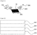
- Figure 1 is a diagram showing a liquid crystal stain inspection device of a polarization plate according to one example of the present application.
- the liquid crystal stain inspection device of the polarization plate in the present application comprises a surface light source (100), a first polarization member (200), a polarization plate (300), a second polarization member (400) and an inspection source (500).
- Figure 2 is a diagram showing a polarization plate according to one example of the present application.
- the polarization plate (300) comprises a polarizer (320) and a quarter wave plate (330) sequentially.
- the quarter wave plate (330) comprises a liquid crystal film (not shown).
- the light transmitted through the first polarization member is applied to the quarter wave plate (330) of the polarization plate (300).
- the liquid crystal stain inspection device of the polarization plate in the present application can easily inspect liquid crystal stains (10) generated on the polarization plate (300) with excellent visibility.
- located sequentially may mean a state where the respective components are located in parallel in a series structure.
- the surface light source (100) is a light source having a uniformly shining surface and no thickness, which can be distinguished from a conventional point or line-shaped light source.
- the liquid crystal stains in the present application are irregular stains as irregularly formed, where in the case of using the point light source without diffusion by a light guide plate, the visibility of the liquid crystal stains is lowered, so that the liquid crystal stains of the polarization plate can be inspected using the surface light source.
- the surface light source (100) may emit unpolarized light vibrating in various directions.
- various types of surface light source lamps emitting various white light or having a continuous spectrum in a spectral range of a visible light region may be used.
- the manufacturing cost and maintenance cost of the liquid crystal stain inspection device of the polarization plate may be inexpensive.
- the surface light source (100) the light that the point light source or the line light source is diffused by the light guide plate to perform the same function as the surface light source may be used.
- the surface light source (100) may emit unpolarized light toward the first polarization member (200).
- the surface light source (100) from which the unpolarized light is emitted may be polarized in a direction parallel to the transmission axis of the first polarization member (200) while penetrating the first polarization member (200).
- the light quantity of the surface light source (100) may be adjusted.
- the surface light source (100) may improve visibility by increasing the light quantity.
- the incident angle of the light emitted from the surface light source (100) may be adjusted.
- the light emitted from the surface light source (100) may have an incident angle of 30° to 60° to the polarization plate (300).
- the incident angle of the light emitted from the surface light source (100) to the polarization plate (300) may be 35° to 55° or 40° to 50°.
- visibility of liquid crystal stains may be excellent.
- the incident angle of the light emitted from the light source (100) is lower than the above-described range, it can be difficult to perform the detection due to a small visual appreciation difference, and when it is higher than the above-described range, it can be difficult to detect liquid crystal stains due to many surface reflections.
- the first polarization member (200) is a part for polarizing the light emitted from the surface light source in a specific direction, which may be disposed so that light is applied from the surface light source.
- the term "polarization member and polarizer” may mean a functional layer exhibiting anisotropic transmission characteristics with respect to incident light while having a transmission axis formed in either direction.
- the polarization member and polarizer may have a function of transmitting light vibrating in one direction from incident light vibrating in various directions, and reflecting or absorbing light vibrating in the other directions.
- a polarizer may be, for example, a reflecting polarizer or an absorbing polarizer, and the first polarization member, the second polarization member and the polarizer of the present application may be absorbing polarizers.
- the term "absorbing polarizer” may mean a layer that transmits light having a direction parallel to a transmission axis from incident light vibrating in various directions, and absorbs and blocks light vibrating in the other directions.
- the absorbing polarizer may have a transmission axis and an absorption axis orthogonal to each other in a plane direction.
- the angle formed by the transmission axis and the absorption axis may be 85° to 95°, or 90°, and the light vibrating in a direction parallel to the transmission axis may be transmitted, and the light vibrating in a direction parallel to the absorption axis may be reflected or absorbed.
- each case of the foregoing may include an error within about ⁇ 15°, an error within about ⁇ 10° or an error within about ⁇ 5°.
- a conventional absorbing polarizer known in the art may be used.
- a stretched polymer film for example, a polyvinyl alcohol (PVA) film or the like, dyed with an iodine compound or an organic dye may be used.
- PVA polyvinyl alcohol
- Such an absorbing polarizer may generally have a transmission axis and an absorption axis orthogonal to the transmission axis.
- the first polarization member (200) may have an absorption axis perpendicular to the polarizer (320) of the polarization plate (300). Specifically, when the first polarization member (200) has an absorption axis in a first direction (shown as ⁇ ), the polarizer (320) of the polarization plate (300) may have an absorption axis in a second direction (shown as ⁇ ) orthogonal to the absorption axis of the first polarization member (200), and the first polarization member (200) and the polarizer (320) of the polarization plate (300) may have transmission axes in a direction (not shown) orthogonal to each absorption axis.
- a first direction shown as ⁇
- the polarizer (320) of the polarization plate (300) may have an absorption axis in a second direction (shown as ⁇ ) orthogonal to the absorption axis of the first polarization member (200)
- the light transmitted through the first polarization member (200) and linearly polarized may form circularly polarized light through the quarter wave plate (330) of the polarization plate (300), as described below, and the circularly polarized light may be reflected by the polarizer (320) of the polarization plate (300), specifically, by the interface between the polarizer (320) of the polarization plate (300) and a protective film (310) to be described below.
- the polarization plate (300) is a sample to be measured for inspecting liquid crystal stains (10), which may be included in an inspection part (not shown).
- the polarization plate (300) may be disposed on the inspection part.
- the polarization plate (300) is disposed so that the light transmitted through the first polarization member (200) is applied to reflect the applied light.
- the light transmitted through the first polarization member (200) and linearly polarized may form circularly polarized light through the quarter wave plate (330) of the polarization plate (300), and the circularly polarized light may be reflected by the polarizer (320) of the polarization plate (300), specifically, by the interface between the polarizer (320) of the polarization plate
- the polarizer (320) of the polarization plate (300) By reflecting the light from the polarizer (320) of the polarization plate (300), it may be reflected from right circularly polarized light to left circularly polarized light or from left circularly polarized light to right circularly polarized light.
- the polarization plate (300) may further comprise a protective film (310) and a release film (340).
- the polarization plate (300) may sequentially comprise a protective film (310), a polarizer (320), a quarter wave plate (330) and a release film (340).
- the polarization plate (300) further comprises a protective film (310) and a release film (340)
- the light transmitted through the first polarization member (200) may be applied to the release film (340) of the polarization plate (300) to be penetrated.
- the protective film (310) is a film attached to protect the polarizer (320), which may be a protective film for a polarizer known in the art, such as a TAC sheet, but is not limited thereto.
- the polarization plate (300) further comprises a pressure-sensitive adhesive layer (not shown) capable of attaching the polarization plate (300) to a panel when applied to an organic light emitting display device to be described below, where in order to protect the pressure-sensitive adhesive layer, the release film (340) may be attached to the pressure-sensitive adhesive layer.
- the pressure-sensitive adhesive layer may be formed between the quarter wave plate and the release film.
- the pressure-sensitive adhesive layer may be composed of an acrylic pressure-sensitive adhesive, a silicone-based pressure-sensitive adhesive or a urethane-based pressure-sensitive adhesive, and a polyethylene terephthalate-based film or a polyolefin-based film may be used as the release film.
- the polarization plate (300) may be a polarization plate for an organic light emitting display device.
- the organic light emitting display device has a disadvantage that it is vulnerable to reflection of external light such as sunlight and lighting due to the exposure of the electrode, so that for blocking reflection of external light on the surface and having dark visual appreciation in a power-off state, it may comprise a polarizer for making the linearly polarized light and a quarter wave plate for making the circularly polarized light.
- the liquid crystal display device is a transmissive display device that changes the traveling direction of light or adjusts the intensity of light by using liquid crystals between two polarization plates, which comprises a polarizer for making linearly polarized light to the polarization plate, but does not require a quarter wave plate.
- the term "quarter wave plate” may mean a phase delay film capable of retarding incident light by 1/4 times its wavelength. Such a quarter wave plate may play a role of making circularly polarized light into linearly polarized light or making linearly polarized light into circularly polarized light.
- the quarter wave plate may have a plane direction phase difference of 50 nm to 250 nm or 90 nm to 200 nm or so for light having a wavelength of 360 nm.
- the term “plane direction phase difference” is a value calculated as "(n x - n y ) X d," where n x is the refractive index of the relevant layer in the planar slow axis direction, n y is the refractive index of the relevant layer in the planar fast axis direction and d is the thickness of the quarter wavelength film.
- the term “slow axis” may mean an axis in the direction representing the highest refractive index in the quarter wave plate, and the slow axis may be used in the same meaning as a phase delay axis in this specification. have.
- the term “fast axis” may mean an axis in the direction showing the lowest refractive index in the quarter wave plate, that is, the direction orthogonal to the slow axis.
- the quarter wave plate (330) of the present application comprises a liquid crystal film.
- the liquid crystal film may sequentially comprise a base film (not shown) and a liquid crystal layer (not shown).
- the quarter wave plate (330) may be a liquid crystal film in which a liquid crystal layer is formed by orienting and polymerizing a polymerizable liquid crystal compound on the base film.
- the liquid crystal layer may comprise a polymerizable liquid crystal compound in a polymerized state.
- the term “polymerizable liquid crystal compound” may mean a compound containing a moiety capable of displaying liquid crystallinity, for example, a mesogen skeleton or the like, and containing one or more polymerizable functional groups.
- the term “that comprises a polymerizable liquid crystal compound in a polymerized state” may mean a state where the liquid crystal compound is polymerized to form a skeleton such as a main chain or a side chain of a liquid crystal polymer in the liquid crystal layer.
- the polymerizable liquid crystal compound may be included in the liquid crystal layer in a horizontally oriented state.
- the term "horizontal orientation” may mean a case in which the optical axis of the liquid crystal layer comprising the polymerized liquid crystal compound has an inclination angle of about 0° to about 25°, about 0° to about 15°, about 0° to about 10°, about 0° to about 5° or about 0° with respect to the plane of the liquid crystal layer.
- the light transmitted through the first polarization member (200) may be reflected from the polarizer (320) of the polarization plate (300).
- the light transmitted through the first polarization member (200) and linearly polarized may be transmitted through the quarter wave plate (330) of the polarization plate (300) and circularly polarized, and the circularly polarized light may be incident on the polarizer (320) of the polarization plate (300) and rotated 180°. That is, the circularly polarized light incident on the polarizer (320) of the polarization plate (300) may be reflected from right circularly polarized light to left circularly polarized light or from left circularly polarized light to right circularly polarized light.
- the reflected light is transmitted through the quarter wave plate (330) of the polarization plate (300), whereby it may be aligned in a direction perpendicular to the light transmitted through the first polarization member (200) and linearly polarized.
- the reflected light when transmitted through a portion of the polarization plate (300) where the liquid crystal stain (10) is present to be linearly polarized, it may be aligned so that some are parallel and some are not parallel to the absorption axis of the second polarization member (400), whereby reflective visual appreciation may vary.
- the reflected light is transmitted through a portion of the polarization plate (300) where the liquid crystal stain (10) is not present to be linearly polarized, all may be aligned perpendicular to the absorption axis of the second polarization member (400), that is, parallel to the transmission axis.
- the light reflected and emitted from the polarizer (320) of the polarization plate (300) may have a reflection angle of 30° to 60° to the polarization plate (300).
- the reflection angle of light reflected and emitted from the polarizer (320) with respect to the polarization plate (300) may be 35° to 55° or 40° to 50°.
- the reflection angle of the light reflected and emitted from the polarizer (320) satisfies the above-described range, visibility of liquid crystal stains may be excellent.
- the reflection angle of the light reflected and emitted from the polarizer (320) of the polarization plate (300) is lower than the above-described range, it can be difficult to perform the detection due to a small visual appreciation difference, and when it is higher than the above-described range, it can be difficult to detect liquid crystal stains due to many surface reflections.
- the second polarization member (400) is a part that transmits and/or absorbs the light reflected from the polarization plate (300) according to the presence or absence of liquid crystal stains of the polarization plate (300), which is disposed so that the light reflected from the polarization plate (300) is applied. Specifically, the light reflected by applying a portion of the polarization plate (300) where liquid crystal stains are present may be partially transmitted through the second polarization member (400) and partially absorbed by the second polarization member (400). Conversely, all the light reflected by applying a portion of the polarization plate (300) where liquid crystal stains do not exist may be transmitted through the second polarization member (400). As the light reflected from the polarization plate is applied to the second polarization member, it is possible to inspect liquid crystal stains of the polarization plate through a color detected from the inspection source.
- the second polarization member (400) may have an absorption axis parallel to the polarizer (320) of the polarization plate (300). That is, the second polarization member (400) may have an absorption axis perpendicular to the first polarization member (200).
- the polarizer (320) of the polarization plate (300) may also have an absorption axis in the second direction (shown as ⁇ ), and the second polarization member (400) and the polarizer (320) of the polarization plate (300) may each have a transmission axis in the first direction (shown as ⁇ ) orthogonal to the absorption axis.
- the second polarization member and the polarizer of the polarization plate have absorption axes in parallel, it is possible to inspect liquid crystal stains of the polarization plate through the light applied to the second polarization member.
- the inspection source (500) is a part for determining the liquid crystal stains (10) of the polarization plate (300) based on the light transmitted through the second polarization member (400), which is disposed so that the light transmitted through the second polarization member (400) is applied.
- the light transmitted through the portion where the thickness difference occurs in the quarter wave plate (330) due to the presence of liquid crystal stains may be partially transmitted through the second polarization member (400) and partially absorbed by the second polarization member (400), whereby it appears green. That is, it may be determined that liquid crystal stains exist in the portion where the light transmitted through the second polarization member (400) appears green.
- all the light transmitted through the portion of the quarter wave plate (330) where the liquid crystal stain does not exist may be transmitted through the second polarization member (400) to show a bright color close to white. That is, it may be determined that liquid crystal stains do not exist in the portion where the light detected from the inspection source (500) shows a bright color.
- the inspection of the liquid crystal stain (10) in the polarization plate may be directly performed using the naked eye, and in another example, the inspection of the liquid crystal stain (10) in the polarization plate may be indirectly performed from an image obtained using an imaging device such as a video camera instead of the naked eye through a computer.
- the present application also relates to a liquid crystal stain inspection method of a polarization plate.
- An exemplary liquid crystal stain inspection method of a polarization plate relates to an inspection method using the liquid crystal stain inspection device of the polarization plate as described above. Therefore, specific matters related to the liquid crystal stain inspection method of the polarization plate to be described below may be equally applied to the contents described in the liquid crystal stain inspection device of the polarization plate, and thus will be omitted.
- the liquid crystal stain inspection method of the polarization plate in the present application comprises steps of transmitting and determining.
- the liquid crystal stain inspection method of the polarization plate in the present application it is possible to easily inspect the liquid crystal stains generated on the polarization plate with excellent visibility.
- the step of transmitting is a step of transmitting light using the liquid crystal stain inspection device of the polarization plate as described above, wherein the light is emitted from the surface light source and sequentially transmitted through the first polarization member, the polarization plate and the second polarization member.
- the specific contents of the surface light source, the first polarization member, the polarization plate, the second polarization member and the traveling of light are the same as previously described in the liquid crystal stain inspection device of the polarization plate, and thus will be omitted.
- the step of determining is a step of determining liquid crystal stains in the polarization plate, which is determined as the liquid crystal stain of the polarization plate based on the light transmitted through the second polarization member and applied to the inspection source. That is, when the light reaches the inspection source from the surface light source to show a green color, it may be determined that liquid crystal stains exist on the polarization plate, and when the light reaches the inspection source from the surface light source to show a bright color close to white, it may be determined that liquid crystal stains do not exist on the polarization plate. Furthermore, the specific contents of the inspection source and the traveling of light are the same as previously described in the liquid crystal stain inspection device of the polarization plate, and thus will be omitted.
- the light applied to the polarization plate may be reflected.
- the light transmitted through the polarizer of the polarization plate may be reflected at the polarizer of the polarization plate, more specifically, the interface between the polarizer of the polarization plate and the protective film.
- the liquid crystal stains of the polarization plate may be inspected through reflection of light. The specific contents of the reflection of the light are the same as previously described in the liquid crystal stain inspection device of the polarization plate, and thus will be omitted.
- a liquid crystal stain inspection device of a polarization plate according to one example of the present application a liquid crystal stain inspection device of a polarization plate according to another example and a liquid crystal stain inspection device of a polarization plate not according to one example, the inspection for detecting the liquid crystal stains of the polarization plate was performed.
- the liquid crystal stain inspection device of the polarization plate used a surface light source as a light source, wherein the surface light source was applied to a first polarization member having an absorption axis in a first direction ( ⁇ ) at an incident angle of 45° to the polarization plate and linearly polarized, and the linearly polarized light was applied to a quarter wave plate of the polarization plate where liquid crystal stains existed and right circularly polarized. Thereafter, the right circularly polarized light was applied to a polarizer of the polarization plate having an absorption axis in a second direction ( ⁇ ), reflected by 180° and left circularly polarized.
- the left circularly polarized light was applied to the quarter wave plate of the polarization plate to be transmitted, whereby it was aligned in a direction perpendicular to the light transmitted through the first polarization member and linearly polarized.
- the linearly polarized light was applied to the second polarization member having an absorption axis in the second direction ( ⁇ ) and transmitted, it was confirmed that liquid crystal stains of the polarization plate were detected through the light inspected from the inspection source to be inspected by the naked eye.
- liquid crystal stain inspection of the polarization plate was performed in the same method as in the liquid crystal stain inspection device of the polarization plate according to one example of the present application, except that in the liquid crystal stain inspection device of the polarization plate according to another example of the present application, the absorption axes of the first polarization member, the polarizer of the polarization plate and the second polarization member were rotated 90°.
- liquid crystal stain inspection of the polarization plate was performed in the same method as in the liquid crystal stain inspection device of the polarization plate according to one example of the present application, except that in the liquid crystal stain inspection device of the polarization plate not according to one example of the present application, a point light source is used instead of the surface light source as the light source.
- the liquid crystal stains of the polarization plate are inspected using the liquid crystal stain inspection device of the polarization plate not according to one example of the present application, the liquid crystal stains of the polarization plate are detected, but the light quantity is not uniform and thus visibility is poor. Contrarily, when the liquid crystal stains of the polarization plate are inspected using the liquid crystal stain inspection devices of the polarization plate according to one example of the present application and another example of the present application, it is possible to inspect the liquid crystal stains of the polarization plate with excellent visibility.
Landscapes
- Physics & Mathematics (AREA)
- General Physics & Mathematics (AREA)
- Chemical & Material Sciences (AREA)
- Optics & Photonics (AREA)
- Immunology (AREA)
- General Health & Medical Sciences (AREA)
- Pathology (AREA)
- Health & Medical Sciences (AREA)
- Life Sciences & Earth Sciences (AREA)
- Analytical Chemistry (AREA)
- Biochemistry (AREA)
- Nonlinear Science (AREA)
- Crystallography & Structural Chemistry (AREA)
- Mathematical Physics (AREA)
- Polarising Elements (AREA)
- Liquid Crystal (AREA)
- Investigating Materials By The Use Of Optical Means Adapted For Particular Applications (AREA)
- Testing Of Optical Devices Or Fibers (AREA)
- Electroluminescent Light Sources (AREA)
Abstract
Description
- The present application relates to a liquid crystal stain inspection device of a polarization plate and a liquid crystal stain inspection method of a polarization plate.
- The present application claims the benefit of priority based on
Korean Patent Application No. 10-2019-0067543 filed on June 7, 2019 - Organic light emitting displays (OLEDs) have been expanded to various applications such as mobiles and TVs.
- Such an organic light emitting display device comprises a polarization plate because a surface light source applied from the outside is reflected due to the metal electrode at the bottom to deteriorate panel visibility in a bright room environment.
- In order to block the reflected light, the polarization plate comprises a quarter wave plate (QWP) that rotates the phase of light 1/4 turn. Such a quarter wave plate may be implemented as a polymer film or a liquid crystal coating. However, in the case of implementing the liquid crystal coating with the quarter wave plate, there was a problem that liquid crystal stains, the color sense whose looks different upon reflection, were caused by the thickness deviation or pressing of the liquid crystal layer or the like.
- There was a problem that such liquid crystal stains were difficultly identified with a general inspection method and more difficultly identified upon attaching a protective film and/or a release film on a finished product of a polarization plate. Accordingly, in order to solve this problem, there is a need for a liquid crystal stain inspection device of a polarization plate and a liquid crystal stain inspection method of a polarization plate.
- It is an object of the present application to provide a liquid crystal stain inspection device of a polarization plate and a liquid crystal stain inspection method of a polarization plate which can easily inspect liquid crystal stains generated on the polarization plate with excellent visibility.
- In order to solve the above object, the liquid crystal stain inspection device of the polarization plate in the present application comprises a surface light source, a first polarization member disposed such that light is applied from the surface light source, a polarization plate disposed such that the light transmitted through the first polarization member is applied and reflecting the applied light, a second polarization member disposed such that the light reflected from the polarization plate is applied, and an inspection source disposed such that the light transmitted through the second polarization member is applied and determining liquid crystal stains of the polarization plate based on the light transmitted through the second polarization member, wherein the polarization plate comprises a polarizer and a quarter wave plate including a liquid crystal film sequentially and the light transmitted through the first polarization member is applied to the quarter wave plate of the polarization plate.
- In addition, the surface light source may emit unpolarized light toward the first polarization member.
- In addition, the light emitted from the surface light source may have an incident angle of 30° to 60° to the polarization plate.
- In addition, the first polarization member may have an absorption axis perpendicular to the polarizer of the polarization plate.
- In addition, the polarization plate may further comprise a protective film and a release film, where it may sequentially comprise the protective film, the polarizer, the quarter wave plate and the release film.
- In addition, the polarization plate may be a polarization plate for an organic light emitting display device.
- In addition, the liquid crystal film may sequentially comprise a base film and a liquid crystal layer.
- In addition, the liquid crystal layer may comprise a polymerizable liquid crystal compound in a polymerized state.
- In addition, the light transmitted through the first polarization member may be reflected from the polarizer of the polarization plate.
- In addition, the light reflected and emitted from the polarizer of the polarization plate may have a reflection angle of 30° to 60° to the polarization plate.
- In addition, the second polarization member may have an absorption axis parallel to the polarizer of the polarization plate.
- In addition, thee light reflected from the polarization plate may be applied to the second polarization member.
- In addition, the liquid crystal stain inspection method of the polarization plate in the present application relates to a liquid crystal stain inspection method of a polarization plate using the liquid crystal stain inspection device of the polarization plate, which comprises steps of emitting light from the surface light source and transmitting the light through the first polarization member, the polarization plate and the second polarization member sequentially, and determining liquid crystal stains of the polarization plate based on the light transmitted through the second polarization member and applied to the inspection source.
- In addition, the light applied to the polarization plate may be reflected.
- According to the liquid crystal stain inspection device of the polarization plate and the liquid crystal stain inspection method of the polarization plate in the present application, it is possible to easily inspect liquid crystal stains generated on the polarization plate with excellent visibility.
-
-
Figure 1 is a diagram showing a liquid crystal stain inspection device of a polarization plate according to one example of the present application. -
Figure 2 is a diagram showing a polarization plate according to one example of the present application. - Hereinafter, a liquid crystal stain inspection device of a polarization plate and a liquid crystal stain inspection method of a polarization plate in the present application will be described with reference to the accompanying drawings, where the accompanying drawings are illustrative, and the liquid crystal stain inspection device of the polarization plate and the liquid crystal stain inspection method of the polarization plate in the present application is not limited to the accompanying drawings.
-
Figure 1 is a diagram showing a liquid crystal stain inspection device of a polarization plate according to one example of the present application. As shown inFigure 1 , the liquid crystal stain inspection device of the polarization plate in the present application comprises a surface light source (100), a first polarization member (200), a polarization plate (300), a second polarization member (400) and an inspection source (500).Figure 2 is a diagram showing a polarization plate according to one example of the present application. As shown inFigure 2 , the polarization plate (300) comprises a polarizer (320) and a quarter wave plate (330) sequentially. Also, the quarter wave plate (330) comprises a liquid crystal film (not shown). In addition, the light transmitted through the first polarization member is applied to the quarter wave plate (330) of the polarization plate (300). The liquid crystal stain inspection device of the polarization plate in the present application can easily inspect liquid crystal stains (10) generated on the polarization plate (300) with excellent visibility. - In this specification, the term "located sequentially" may mean a state where the respective components are located in parallel in a series structure.
- The surface light source (100) is a light source having a uniformly shining surface and no thickness, which can be distinguished from a conventional point or line-shaped light source. In one example, the liquid crystal stains in the present application are irregular stains as irregularly formed, where in the case of using the point light source without diffusion by a light guide plate, the visibility of the liquid crystal stains is lowered, so that the liquid crystal stains of the polarization plate can be inspected using the surface light source.
- The surface light source (100) may emit unpolarized light vibrating in various directions. As the surface light source (100), various types of surface light source lamps emitting various white light or having a continuous spectrum in a spectral range of a visible light region may be used. By using the unpolarized light as the surface light source, the manufacturing cost and maintenance cost of the liquid crystal stain inspection device of the polarization plate may be inexpensive. In another example, as the surface light source (100), the light that the point light source or the line light source is diffused by the light guide plate to perform the same function as the surface light source may be used.
- The surface light source (100) may emit unpolarized light toward the first polarization member (200). The surface light source (100) from which the unpolarized light is emitted may be polarized in a direction parallel to the transmission axis of the first polarization member (200) while penetrating the first polarization member (200).
- In addition, the light quantity of the surface light source (100) may be adjusted. For example, the surface light source (100) may improve visibility by increasing the light quantity.
- In addition, the incident angle of the light emitted from the surface light source (100) may be adjusted. In one example, the light emitted from the surface light source (100) may have an incident angle of 30° to 60° to the polarization plate (300). For example, the incident angle of the light emitted from the surface light source (100) to the polarization plate (300) may be 35° to 55° or 40° to 50°. As the incident angle of the light emitted from the surface light source (100) satisfies the above-described range, visibility of liquid crystal stains may be excellent. In addition, when the incident angle of the light emitted from the light source (100) is lower than the above-described range, it can be difficult to perform the detection due to a small visual appreciation difference, and when it is higher than the above-described range, it can be difficult to detect liquid crystal stains due to many surface reflections.
- The first polarization member (200) is a part for polarizing the light emitted from the surface light source in a specific direction, which may be disposed so that light is applied from the surface light source.
- In this specification, the term "polarization member and polarizer" may mean a functional layer exhibiting anisotropic transmission characteristics with respect to incident light while having a transmission axis formed in either direction. For example, the polarization member and polarizer may have a function of transmitting light vibrating in one direction from incident light vibrating in various directions, and reflecting or absorbing light vibrating in the other directions. Such a polarizer may be, for example, a reflecting polarizer or an absorbing polarizer, and the first polarization member, the second polarization member and the polarizer of the present application may be absorbing polarizers.
- In this specification, the term "absorbing polarizer" may mean a layer that transmits light having a direction parallel to a transmission axis from incident light vibrating in various directions, and absorbs and blocks light vibrating in the other directions. In one example, the absorbing polarizer may have a transmission axis and an absorption axis orthogonal to each other in a plane direction. For example, the angle formed by the transmission axis and the absorption axis may be 85° to 95°, or 90°, and the light vibrating in a direction parallel to the transmission axis may be transmitted, and the light vibrating in a direction parallel to the absorption axis may be reflected or absorbed.
- In this specification, when the term such as vertical, parallel, orthogonal or horizontal is used while defining an angle, it means substantially vertical, parallel, orthogonal or horizontal to the extent that the desired effect is not impaired, which includes, for example, an error that takes a production error or a deviation (variation), and the like, into account. For example, each case of the foregoing may include an error within about ±15°, an error within about ±10° or an error within about ±5°.
- As the absorbing polarizer, a conventional absorbing polarizer known in the art may be used. For example, as the absorbing polarizer, a stretched polymer film, for example, a polyvinyl alcohol (PVA) film or the like, dyed with an iodine compound or an organic dye may be used. Such an absorbing polarizer may generally have a transmission axis and an absorption axis orthogonal to the transmission axis.
- In one example, the first polarization member (200) may have an absorption axis perpendicular to the polarizer (320) of the polarization plate (300). Specifically, when the first polarization member (200) has an absorption axis in a first direction (shown as ↔), the polarizer (320) of the polarization plate (300) may have an absorption axis in a second direction (shown as ↕) orthogonal to the absorption axis of the first polarization member (200), and the first polarization member (200) and the polarizer (320) of the polarization plate (300) may have transmission axes in a direction (not shown) orthogonal to each absorption axis. As the first polarization member and the polarizer of the polarization plate have absorption axes perpendicularly, the light transmitted through the first polarization member (200) and linearly polarized may form circularly polarized light through the quarter wave plate (330) of the polarization plate (300), as described below, and the circularly polarized light may be reflected by the polarizer (320) of the polarization plate (300), specifically, by the interface between the polarizer (320) of the polarization plate (300) and a protective film (310) to be described below.
- The polarization plate (300) is a sample to be measured for inspecting liquid crystal stains (10), which may be included in an inspection part (not shown). For example, the polarization plate (300) may be disposed on the inspection part.
- The polarization plate (300) is disposed so that the light transmitted through the first polarization member (200) is applied to reflect the applied light. For example, the light transmitted through the first polarization member (200) and linearly polarized may form circularly polarized light through the quarter wave plate (330) of the polarization plate (300), and the circularly polarized light may be reflected by the polarizer (320) of the polarization plate (300), specifically, by the interface between the polarizer (320) of the polarization plate
- (300) and a protective film (310) to be described below. By reflecting the light from the polarizer (320) of the polarization plate (300), it may be reflected from right circularly polarized light to left circularly polarized light or from left circularly polarized light to right circularly polarized light.
- In addition, as shown in
Figure 2 , the polarization plate (300) may further comprise a protective film (310) and a release film (340). Specifically, the polarization plate (300) may sequentially comprise a protective film (310), a polarizer (320), a quarter wave plate (330) and a release film (340). When the polarization plate (300) further comprises a protective film (310) and a release film (340), the light transmitted through the first polarization member (200) may be applied to the release film (340) of the polarization plate (300) to be penetrated. - The protective film (310) is a film attached to protect the polarizer (320), which may be a protective film for a polarizer known in the art, such as a TAC sheet, but is not limited thereto.
- In addition, the polarization plate (300) further comprises a pressure-sensitive adhesive layer (not shown) capable of attaching the polarization plate (300) to a panel when applied to an organic light emitting display device to be described below, where in order to protect the pressure-sensitive adhesive layer, the release film (340) may be attached to the pressure-sensitive adhesive layer. Specifically, the pressure-sensitive adhesive layer may be formed between the quarter wave plate and the release film. The pressure-sensitive adhesive layer may be composed of an acrylic pressure-sensitive adhesive, a silicone-based pressure-sensitive adhesive or a urethane-based pressure-sensitive adhesive, and a polyethylene terephthalate-based film or a polyolefin-based film may be used as the release film.
- In one example, the polarization plate (300) may be a polarization plate for an organic light emitting display device. Specifically, the organic light emitting display device has a disadvantage that it is vulnerable to reflection of external light such as sunlight and lighting due to the exposure of the electrode, so that for blocking reflection of external light on the surface and having dark visual appreciation in a power-off state, it may comprise a polarizer for making the linearly polarized light and a quarter wave plate for making the circularly polarized light. However, the liquid crystal display device is a transmissive display device that changes the traveling direction of light or adjusts the intensity of light by using liquid crystals between two polarization plates, which comprises a polarizer for making linearly polarized light to the polarization plate, but does not require a quarter wave plate.
- In this specification, the term "quarter wave plate" may mean a phase delay film capable of retarding incident light by 1/4 times its wavelength. Such a quarter wave plate may play a role of making circularly polarized light into linearly polarized light or making linearly polarized light into circularly polarized light. In one example, the quarter wave plate may have a plane direction phase difference of 50 nm to 250 nm or 90 nm to 200 nm or so for light having a wavelength of 360 nm. In this specification, the term "plane direction phase difference" is a value calculated as "(nx - ny) X d," where nx is the refractive index of the relevant layer in the planar slow axis direction, ny is the refractive index of the relevant layer in the planar fast axis direction and d is the thickness of the quarter wavelength film. In addition, in this specification, the term "slow axis" may mean an axis in the direction representing the highest refractive index in the quarter wave plate, and the slow axis may be used in the same meaning as a phase delay axis in this specification. have. In this specification, the term "fast axis" may mean an axis in the direction showing the lowest refractive index in the quarter wave plate, that is, the direction orthogonal to the slow axis.
- In one example, the quarter wave plate (330) of the present application comprises a liquid crystal film. For example, the liquid crystal film may sequentially comprise a base film (not shown) and a liquid crystal layer (not shown). Specifically, the quarter wave plate (330) may be a liquid crystal film in which a liquid crystal layer is formed by orienting and polymerizing a polymerizable liquid crystal compound on the base film.
- The liquid crystal layer may comprise a polymerizable liquid crystal compound in a polymerized state. In this specification, the term "polymerizable liquid crystal compound" may mean a compound containing a moiety capable of displaying liquid crystallinity, for example, a mesogen skeleton or the like, and containing one or more polymerizable functional groups. In addition, in this specification, the term "that comprises a polymerizable liquid crystal compound in a polymerized state" may mean a state where the liquid crystal compound is polymerized to form a skeleton such as a main chain or a side chain of a liquid crystal polymer in the liquid crystal layer. For example, the polymerizable liquid crystal compound may be included in the liquid crystal layer in a horizontally oriented state. In this specification, the term "horizontal orientation" may mean a case in which the optical axis of the liquid crystal layer comprising the polymerized liquid crystal compound has an inclination angle of about 0° to about 25°, about 0° to about 15°, about 0° to about 10°, about 0° to about 5° or about 0° with respect to the plane of the liquid crystal layer.
- In one example, the light transmitted through the first polarization member (200) may be reflected from the polarizer (320) of the polarization plate (300). Specifically, the light transmitted through the first polarization member (200) and linearly polarized may be transmitted through the quarter wave plate (330) of the polarization plate (300) and circularly polarized, and the circularly polarized light may be incident on the polarizer (320) of the polarization plate (300) and rotated 180°. That is, the circularly polarized light incident on the polarizer (320) of the polarization plate (300) may be reflected from right circularly polarized light to left circularly polarized light or from left circularly polarized light to right circularly polarized light.
- At this time, the reflected light is transmitted through the quarter wave plate (330) of the polarization plate (300), whereby it may be aligned in a direction perpendicular to the light transmitted through the first polarization member (200) and linearly polarized. For example, when the reflected light is transmitted through a portion of the polarization plate (300) where the liquid crystal stain (10) is present to be linearly polarized, it may be aligned so that some are parallel and some are not parallel to the absorption axis of the second polarization member (400), whereby reflective visual appreciation may vary. In addition, when the reflected light is transmitted through a portion of the polarization plate (300) where the liquid crystal stain (10) is not present to be linearly polarized, all may be aligned perpendicular to the absorption axis of the second polarization member (400), that is, parallel to the transmission axis.
- At this time, the light reflected and emitted from the polarizer (320) of the polarization plate (300) may have a reflection angle of 30° to 60° to the polarization plate (300). For example, the reflection angle of light reflected and emitted from the polarizer (320) with respect to the polarization plate (300) may be 35° to 55° or 40° to 50°. As the reflection angle of the light reflected and emitted from the polarizer (320) satisfies the above-described range, visibility of liquid crystal stains may be excellent. In addition, when the reflection angle of the light reflected and emitted from the polarizer (320) of the polarization plate (300) is lower than the above-described range, it can be difficult to perform the detection due to a small visual appreciation difference, and when it is higher than the above-described range, it can be difficult to detect liquid crystal stains due to many surface reflections.
- The second polarization member (400) is a part that transmits and/or absorbs the light reflected from the polarization plate (300) according to the presence or absence of liquid crystal stains of the polarization plate (300), which is disposed so that the light reflected from the polarization plate (300) is applied. Specifically, the light reflected by applying a portion of the polarization plate (300) where liquid crystal stains are present may be partially transmitted through the second polarization member (400) and partially absorbed by the second polarization member (400). Conversely, all the light reflected by applying a portion of the polarization plate (300) where liquid crystal stains do not exist may be transmitted through the second polarization member (400). As the light reflected from the polarization plate is applied to the second polarization member, it is possible to inspect liquid crystal stains of the polarization plate through a color detected from the inspection source.
- In one example, the second polarization member (400) may have an absorption axis parallel to the polarizer (320) of the polarization plate (300). That is, the second polarization member (400) may have an absorption axis perpendicular to the first polarization member (200). Specifically, when the second polarization member (400) has an absorption axis in the second direction (shown as ↕), the polarizer (320) of the polarization plate (300) may also have an absorption axis in the second direction (shown as ↕), and the second polarization member (400) and the polarizer (320) of the polarization plate (300) may each have a transmission axis in the first direction (shown as ↔) orthogonal to the absorption axis. As the second polarization member and the polarizer of the polarization plate have absorption axes in parallel, it is possible to inspect liquid crystal stains of the polarization plate through the light applied to the second polarization member.
- The inspection source (500) is a part for determining the liquid crystal stains (10) of the polarization plate (300) based on the light transmitted through the second polarization member (400), which is disposed so that the light transmitted through the second polarization member (400) is applied. Specifically, the light transmitted through the portion where the thickness difference occurs in the quarter wave plate (330) due to the presence of liquid crystal stains may be partially transmitted through the second polarization member (400) and partially absorbed by the second polarization member (400), whereby it appears green. That is, it may be determined that liquid crystal stains exist in the portion where the light transmitted through the second polarization member (400) appears green. In addition, all the light transmitted through the portion of the quarter wave plate (330) where the liquid crystal stain does not exist may be transmitted through the second polarization member (400) to show a bright color close to white. That is, it may be determined that liquid crystal stains do not exist in the portion where the light detected from the inspection source (500) shows a bright color.
- In one example, in the inspection source (500), the inspection of the liquid crystal stain (10) in the polarization plate may be directly performed using the naked eye, and in another example, the inspection of the liquid crystal stain (10) in the polarization plate may be indirectly performed from an image obtained using an imaging device such as a video camera instead of the naked eye through a computer.
- The present application also relates to a liquid crystal stain inspection method of a polarization plate. An exemplary liquid crystal stain inspection method of a polarization plate relates to an inspection method using the liquid crystal stain inspection device of the polarization plate as described above. Therefore, specific matters related to the liquid crystal stain inspection method of the polarization plate to be described below may be equally applied to the contents described in the liquid crystal stain inspection device of the polarization plate, and thus will be omitted.
- The liquid crystal stain inspection method of the polarization plate in the present application comprises steps of transmitting and determining. By using the liquid crystal stain inspection method of the polarization plate in the present application, it is possible to easily inspect the liquid crystal stains generated on the polarization plate with excellent visibility.
- The step of transmitting is a step of transmitting light using the liquid crystal stain inspection device of the polarization plate as described above, wherein the light is emitted from the surface light source and sequentially transmitted through the first polarization member, the polarization plate and the second polarization member. The specific contents of the surface light source, the first polarization member, the polarization plate, the second polarization member and the traveling of light are the same as previously described in the liquid crystal stain inspection device of the polarization plate, and thus will be omitted.
- The step of determining is a step of determining liquid crystal stains in the polarization plate, which is determined as the liquid crystal stain of the polarization plate based on the light transmitted through the second polarization member and applied to the inspection source. That is, when the light reaches the inspection source from the surface light source to show a green color, it may be determined that liquid crystal stains exist on the polarization plate, and when the light reaches the inspection source from the surface light source to show a bright color close to white, it may be determined that liquid crystal stains do not exist on the polarization plate. Furthermore, the specific contents of the inspection source and the traveling of light are the same as previously described in the liquid crystal stain inspection device of the polarization plate, and thus will be omitted.
- In one example, the light applied to the polarization plate may be reflected. Specifically, the light transmitted through the polarizer of the polarization plate may be reflected at the polarizer of the polarization plate, more specifically, the interface between the polarizer of the polarization plate and the protective film. In the polarization plate, the liquid crystal stains of the polarization plate may be inspected through reflection of light. The specific contents of the reflection of the light are the same as previously described in the liquid crystal stain inspection device of the polarization plate, and thus will be omitted.
- Using a liquid crystal stain inspection device of a polarization plate according to one example of the present application, a liquid crystal stain inspection device of a polarization plate according to another example and a liquid crystal stain inspection device of a polarization plate not according to one example, the inspection for detecting the liquid crystal stains of the polarization plate was performed.
- The liquid crystal stain inspection device of the polarization plate according to one example of the present application used a surface light source as a light source, wherein the surface light source was applied to a first polarization member having an absorption axis in a first direction (↔) at an incident angle of 45° to the polarization plate and linearly polarized, and the linearly polarized light was applied to a quarter wave plate of the polarization plate where liquid crystal stains existed and right circularly polarized. Thereafter, the right circularly polarized light was applied to a polarizer of the polarization plate having an absorption axis in a second direction (↕), reflected by 180° and left circularly polarized. Thereafter, the left circularly polarized light was applied to the quarter wave plate of the polarization plate to be transmitted, whereby it was aligned in a direction perpendicular to the light transmitted through the first polarization member and linearly polarized. Thereafter, as the linearly polarized light was applied to the second polarization member having an absorption axis in the second direction (↕) and transmitted, it was confirmed that liquid crystal stains of the polarization plate were detected through the light inspected from the inspection source to be inspected by the naked eye.
- In addition, the liquid crystal stain inspection of the polarization plate was performed in the same method as in the liquid crystal stain inspection device of the polarization plate according to one example of the present application, except that in the liquid crystal stain inspection device of the polarization plate according to another example of the present application, the absorption axes of the first polarization member, the polarizer of the polarization plate and the second polarization member were rotated 90°.
- In addition, the liquid crystal stain inspection of the polarization plate was performed in the same method as in the liquid crystal stain inspection device of the polarization plate according to one example of the present application, except that in the liquid crystal stain inspection device of the polarization plate not according to one example of the present application, a point light source is used instead of the surface light source as the light source.
- That is, when the liquid crystal stains of the polarization plate are inspected using the liquid crystal stain inspection device of the polarization plate not according to one example of the present application, the liquid crystal stains of the polarization plate are detected, but the light quantity is not uniform and thus visibility is poor. Contrarily, when the liquid crystal stains of the polarization plate are inspected using the liquid crystal stain inspection devices of the polarization plate according to one example of the present application and another example of the present application, it is possible to inspect the liquid crystal stains of the polarization plate with excellent visibility.
-
- 10:
- liquid crystal stain
- 100:
- surface light source
- 200:
- first polarization member
- 300:
- polarization plate
- 310:
- protective film
- 320:
- polarizer
- 330:
- quarter wave plate
- 340:
- release film
- 400:
- second polarization member
- 500:
- inspection source
Claims (13)
- A liquid crystal stain inspection device of a polarization plate comprising:a surface light source;a first polarization member disposed such that light is applied from the surface light source;a polarization plate disposed such that the light transmitted through the first polarization member is applied, and reflecting the applied light;a second polarization member disposed such that the light reflected from the polarization plate is applied; andan inspection source disposed such that the light transmitted through the second polarization member is applied, and determining liquid crystal stains of the polarization plate based on the light transmitted through the second polarization member, whereinthe polarization plate comprises a polarizer and a quarter wave plate including a liquid crystal film sequentially andthe light transmitted through the first polarization member is applied to the quarter wave plate of the polarization plate.
- The liquid crystal stain inspection device of a polarization plate according to claim 1, wherein the surface light source emits unpolarized light toward the first polarization member.
- The liquid crystal stain inspection device of a polarization plate according to claim 2, wherein the light emitted from the surface light source has an incident angle of 30° to 60° to the polarization plate.
- The liquid crystal stain inspection device of a polarization plate according to claim 1, wherein the first polarization member has an absorption axis perpendicular to the polarizer of the polarization plate.
- The liquid crystal stain inspection device of a polarization plate according to claim 1, wherein the polarization plate further comprises a protective film and a release film, where it sequentially comprises the protective film, the polarizer, the quarter wave plate and the release film.
- The liquid crystal stain inspection device of a polarization plate according to claim 1, wherein the polarization plate is a polarization plate for an organic light emitting display device.
- The liquid crystal stain inspection device of a polarization plate according to claim 1, wherein the liquid crystal film sequentially comprises a base film and a liquid crystal layer.
- The liquid crystal stain inspection device of a polarization plate according to claim 7, wherein the liquid crystal layer comprises a polymerizable liquid crystal compound in a polymerized state.
- The liquid crystal stain inspection device of a polarization plate according to claim 1, wherein the light transmitted through the first polarization member is reflected from the polarizer of the polarization plate.
- The liquid crystal stain inspection device of a polarization plate according to claim 1, wherein the light reflected and emitted from the polarization plate has a reflection angle of 30° to 60° to the polarization plate.
- The liquid crystal stain inspection device of a polarization plate according to claim 1, wherein the second polarization member has an absorption axis parallel to the polarizer of the polarization plate.
- A liquid crystal stain inspection method of a polarization plate related to a liquid crystal stain inspection method of a polarization plate using the liquid crystal stain inspection device of the polarization plate according to claim 1, which comprises steps of:emitting light from the surface light source and transmitting the light through the first polarization member, the polarization plate and the second polarization member sequentially; anddetermining liquid crystal stains of the polarization plate based on the light transmitted through the second polarization member and applied to the inspection source.
- The liquid crystal stain inspection method of a polarization plate according to claim 12, wherein the light applied to the polarization plate is reflected.
Applications Claiming Priority (2)
| Application Number | Priority Date | Filing Date | Title |
|---|---|---|---|
| KR1020190067543A KR102486442B1 (en) | 2019-06-07 | 2019-06-07 | Device for testing liquid crystal stain of polarizing plate and method for testing liquid crystal stain of polarizing plate |
| PCT/KR2020/003256 WO2020246691A1 (en) | 2019-06-07 | 2020-03-09 | Device for detecting liquid crystal mura in polarizing plate, and method for detecting liquid crystal mura in polarizing plate |
Publications (3)
| Publication Number | Publication Date |
|---|---|
| EP3982193A1 true EP3982193A1 (en) | 2022-04-13 |
| EP3982193A4 EP3982193A4 (en) | 2022-07-27 |
| EP3982193B1 EP3982193B1 (en) | 2025-10-08 |
Family
ID=73652455
Family Applications (1)
| Application Number | Title | Priority Date | Filing Date |
|---|---|---|---|
| EP20818594.2A Active EP3982193B1 (en) | 2019-06-07 | 2020-03-09 | Device for detecting liquid crystal mura in polarizing plate, and method for detecting liquid crystal mura in polarizing plate |
Country Status (6)
| Country | Link |
|---|---|
| US (1) | US12352701B2 (en) |
| EP (1) | EP3982193B1 (en) |
| JP (1) | JP7410979B2 (en) |
| KR (1) | KR102486442B1 (en) |
| CN (1) | CN113841083B (en) |
| WO (1) | WO2020246691A1 (en) |
Families Citing this family (1)
| Publication number | Priority date | Publication date | Assignee | Title |
|---|---|---|---|---|
| JP7256567B1 (en) * | 2022-04-28 | 2023-04-12 | ニシハツ産業株式会社 | Seaweed foreign matter detection device |
Family Cites Families (34)
| Publication number | Priority date | Publication date | Assignee | Title |
|---|---|---|---|---|
| US5973760A (en) * | 1997-08-06 | 1999-10-26 | Rockwell Science Center, Inc. | Display apparatus having quarter-wave plate positioned to eliminate conflicts with polarized sunglasses |
| JP3401743B2 (en) | 1997-10-22 | 2003-04-28 | 日東電工株式会社 | Polarizing element, polarized light source device and liquid crystal display device |
| JP2001116925A (en) * | 1999-10-20 | 2001-04-27 | Sumitomo Chem Co Ltd | Optical sheet inspection method |
| JP4516648B2 (en) | 1999-12-01 | 2010-08-04 | 住友化学株式会社 | Inspection method of composite polarizing plate |
| US6661482B2 (en) * | 2001-10-05 | 2003-12-09 | Nitto Denko Corporation | Polarizing element, optical element, and liquid crystal display |
| CN100399075C (en) * | 2002-04-23 | 2008-07-02 | 日东电工株式会社 | Polarization member, polarized light source and image display device using the same |
| JP2004029694A (en) * | 2002-05-02 | 2004-01-29 | Casio Comput Co Ltd | Liquid crystal display |
| JP2004163664A (en) * | 2002-11-13 | 2004-06-10 | Dainippon Printing Co Ltd | Method of inspecting cholesteric liquid crystal layer, inspection apparatus thereof, and method of manufacturing cholesteric liquid crystal layer |
| JP4529366B2 (en) | 2003-03-26 | 2010-08-25 | 株式会社ニコン | Defect inspection apparatus, defect inspection method, and hole pattern inspection method |
| JP4362335B2 (en) * | 2003-08-27 | 2009-11-11 | エスペックテクノ株式会社 | Inspection device |
| JP2006078426A (en) * | 2004-09-13 | 2006-03-23 | Konica Minolta Holdings Inc | Apparatus and method for inspecting defect |
| JP4794839B2 (en) * | 2004-09-17 | 2011-10-19 | キヤノン株式会社 | Reflective liquid crystal display |
| US20070075279A1 (en) | 2005-09-30 | 2007-04-05 | Intergral Vision, Inc. | Method and system for automatically inspecting a display including a layer of liquid crystal material |
| JP2010503862A (en) | 2006-09-12 | 2010-02-04 | ルドルフテクノロジーズ インコーポレイテッド | Polarization imaging |
| JP5156306B2 (en) * | 2007-09-14 | 2013-03-06 | 大塚電子株式会社 | Optical anisotropy measuring apparatus and optical anisotropy measuring method |
| US20090161044A1 (en) * | 2007-12-21 | 2009-06-25 | Zhibing Ge | Wide viewing angle circular polarizers |
| KR101057626B1 (en) * | 2008-01-07 | 2011-08-19 | 주식회사 엘지화학 | Polarizer Stain Inspection Method Using Image Analysis and Polarizer Stain Automatic Inspection System Using The Same |
| JP2012068641A (en) | 2008-04-14 | 2012-04-05 | Nitto Denko Corp | Optical display device manufacturing system and optical display device manufacturing method |
| JP2011149741A (en) | 2010-01-19 | 2011-08-04 | Sumitomo Chemical Co Ltd | Inspection method of polarization plate and manufacturing method of polarization plate |
| JP2012053077A (en) | 2010-08-31 | 2012-03-15 | Sumitomo Chemical Co Ltd | Rolled polarizing plate set, method for manufacturing the same, and method for manufacturing liquid crystal panel |
| JP2012093664A (en) * | 2010-10-29 | 2012-05-17 | Sumitomo Chemical Co Ltd | Roll-like polarizing plate set and method for manufacturing the same, and method for manufacturing liquid crystal panel |
| JP5806837B2 (en) | 2011-04-11 | 2015-11-10 | 株式会社モリテックス | Optical anisotropy parameter measuring device, measuring method and measuring program |
| TW201400800A (en) * | 2012-06-18 | 2014-01-01 | Fujifilm Corp | Inspection device and inspection method of filter patterned retarder |
| WO2014196637A1 (en) * | 2013-06-06 | 2014-12-11 | 富士フイルム株式会社 | Optical sheet member and image display device employing same |
| JP6766318B2 (en) * | 2015-04-15 | 2020-10-14 | 大日本印刷株式会社 | Optical film, transfer film, image display device, optical film manufacturing method and transfer film manufacturing method |
| CN107615051A (en) | 2015-06-05 | 2018-01-19 | 住友化学株式会社 | The defects of transmitance film inspection method, the manufacture method of linear polarization piece film and the manufacture method of polarization plates |
| JP6604805B2 (en) * | 2015-09-30 | 2019-11-13 | 日東電工株式会社 | Polarizer inspection method and polarizing plate manufacturing method |
| CN107643292B (en) | 2016-07-20 | 2021-05-04 | 南京造币有限公司 | A surface detection device and method based on liquid crystal glass |
| KR20180050802A (en) | 2016-11-07 | 2018-05-16 | 주식회사 엘지화학 | Organic Light-Emitting Device |
| TWI664419B (en) | 2017-07-28 | 2019-07-01 | 南韓商Lg化學股份有限公司 | Device and method for detecting defect of optical film |
| KR102430497B1 (en) | 2017-12-07 | 2022-08-08 | 삼성전자주식회사 | Manufacturing method of light emitting device |
| JP7392278B2 (en) * | 2019-03-29 | 2023-12-06 | 東洋紡株式会社 | Method for manufacturing liquid crystal compound laminate and method for inspecting liquid crystal compound layer |
| JP7404635B2 (en) * | 2019-03-29 | 2023-12-26 | 東洋紡株式会社 | Method for producing aligned liquid crystal compound layer laminate |
| KR102871822B1 (en) * | 2019-05-15 | 2025-10-15 | 스미또모 가가꾸 가부시키가이샤 | Inspection method of optical film and manufacturing method of optical film |
-
2019
- 2019-06-07 KR KR1020190067543A patent/KR102486442B1/en active Active
-
2020
- 2020-03-09 EP EP20818594.2A patent/EP3982193B1/en active Active
- 2020-03-09 JP JP2021568603A patent/JP7410979B2/en active Active
- 2020-03-09 CN CN202080036418.1A patent/CN113841083B/en active Active
- 2020-03-09 WO PCT/KR2020/003256 patent/WO2020246691A1/en not_active Ceased
- 2020-03-09 US US17/611,873 patent/US12352701B2/en active Active
Also Published As
| Publication number | Publication date |
|---|---|
| KR20200140638A (en) | 2020-12-16 |
| US20220228994A1 (en) | 2022-07-21 |
| JP2022532427A (en) | 2022-07-14 |
| EP3982193B1 (en) | 2025-10-08 |
| JP7410979B2 (en) | 2024-01-10 |
| CN113841083A (en) | 2021-12-24 |
| EP3982193A4 (en) | 2022-07-27 |
| KR102486442B1 (en) | 2023-01-09 |
| CN113841083B (en) | 2024-09-03 |
| WO2020246691A1 (en) | 2020-12-10 |
| US12352701B2 (en) | 2025-07-08 |
Similar Documents
| Publication | Publication Date | Title |
|---|---|---|
| JP5051874B2 (en) | Laminated film manufacturing method, laminated film defect detection method, laminated film defect detection apparatus | |
| US8982300B2 (en) | Viewing angle controlling system, and image display device using the same | |
| CN101910923B (en) | Video image evaluation equipment | |
| US7030949B2 (en) | Optical display including a cholesteric layer, a display device and a diffusing layer on an exit side of the cholesteric layer | |
| US20100053520A1 (en) | Very Thin Achromatic Quarter Wave Film Laminate for Transflective LCD and Method for Producing the Same | |
| CN109036163A (en) | A kind of display device and its environment light detection method | |
| WO2016088683A1 (en) | Free-floating image display device | |
| WO2007132818A1 (en) | Inspecting system for board subjected to inspection and method for inspecting board subjected to inspection | |
| EP3982193B1 (en) | Device for detecting liquid crystal mura in polarizing plate, and method for detecting liquid crystal mura in polarizing plate | |
| KR102063047B1 (en) | Optical Film | |
| KR102713733B1 (en) | Device for testing adhesive stain of polarizing plate | |
| US11860480B2 (en) | Liquid crystal display device | |
| KR101995722B1 (en) | Optical isolating device | |
| KR102041807B1 (en) | Device for testing optical properties and method for testing optical properties | |
| KR20100057989A (en) | Transparent display device | |
| US8454179B2 (en) | Video image appreciation system | |
| KR102438678B1 (en) | Polarizer | |
| KR20230080146A (en) | Display device and the method of manufacturing of the same | |
| CN1101942C (en) | Reflection-type liquid crystal display | |
| US20230314868A1 (en) | Liquid crystal display device | |
| KR20210007465A (en) | Polarizing Plate | |
| US20250251284A1 (en) | Interference color evaluation method, optical film, polarizing plate, and image display device | |
| WO2018070827A1 (en) | Polarization conversion element and optical isolation apparatus | |
| KR20180065668A (en) | Apparatus For Inspecting Array Substrate | |
| JP2011033564A (en) | Optical film inspection method |
Legal Events
| Date | Code | Title | Description |
|---|---|---|---|
| STAA | Information on the status of an ep patent application or granted ep patent |
Free format text: STATUS: THE INTERNATIONAL PUBLICATION HAS BEEN MADE |
|
| PUAI | Public reference made under article 153(3) epc to a published international application that has entered the european phase |
Free format text: ORIGINAL CODE: 0009012 |
|
| STAA | Information on the status of an ep patent application or granted ep patent |
Free format text: STATUS: REQUEST FOR EXAMINATION WAS MADE |
|
| 17P | Request for examination filed |
Effective date: 20211110 |
|
| AK | Designated contracting states |
Kind code of ref document: A1 Designated state(s): AL AT BE BG CH CY CZ DE DK EE ES FI FR GB GR HR HU IE IS IT LI LT LU LV MC MK MT NL NO PL PT RO RS SE SI SK SM TR |
|
| A4 | Supplementary search report drawn up and despatched |
Effective date: 20220629 |
|
| RIC1 | Information provided on ipc code assigned before grant |
Ipc: G01N 21/95 20060101ALI20220623BHEP Ipc: G01N 21/88 20060101ALI20220623BHEP Ipc: G02F 1/1335 20060101ALI20220623BHEP Ipc: G02F 1/13 20060101AFI20220623BHEP |
|
| DAV | Request for validation of the european patent (deleted) | ||
| DAX | Request for extension of the european patent (deleted) | ||
| STAA | Information on the status of an ep patent application or granted ep patent |
Free format text: STATUS: EXAMINATION IS IN PROGRESS |
|
| 17Q | First examination report despatched |
Effective date: 20230802 |
|
| RAP1 | Party data changed (applicant data changed or rights of an application transferred) |
Owner name: SHANJIN OPTOELECTRONICS (SUZHOU) CO., LTD. |
|
| GRAP | Despatch of communication of intention to grant a patent |
Free format text: ORIGINAL CODE: EPIDOSNIGR1 |
|
| STAA | Information on the status of an ep patent application or granted ep patent |
Free format text: STATUS: GRANT OF PATENT IS INTENDED |
|
| INTG | Intention to grant announced |
Effective date: 20250527 |
|
| GRAS | Grant fee paid |
Free format text: ORIGINAL CODE: EPIDOSNIGR3 |
|
| GRAA | (expected) grant |
Free format text: ORIGINAL CODE: 0009210 |
|
| STAA | Information on the status of an ep patent application or granted ep patent |
Free format text: STATUS: THE PATENT HAS BEEN GRANTED |
|
| AK | Designated contracting states |
Kind code of ref document: B1 Designated state(s): AL AT BE BG CH CY CZ DE DK EE ES FI FR GB GR HR HU IE IS IT LI LT LU LV MC MK MT NL NO PL PT RO RS SE SI SK SM TR |
|
| REG | Reference to a national code |
Ref country code: GB Ref legal event code: FG4D Ref country code: CH Ref legal event code: F10 Free format text: ST27 STATUS EVENT CODE: U-0-0-F10-F00 (AS PROVIDED BY THE NATIONAL OFFICE) Effective date: 20251008 |
|
| REG | Reference to a national code |
Ref country code: DE Ref legal event code: R096 Ref document number: 602020060195 Country of ref document: DE |
|
| REG | Reference to a national code |
Ref country code: IE Ref legal event code: FG4D |
|
| REG | Reference to a national code |
Ref country code: NL Ref legal event code: MP Effective date: 20251008 |
|
| REG | Reference to a national code |
Ref country code: AT Ref legal event code: MK05 Ref document number: 1845301 Country of ref document: AT Kind code of ref document: T Effective date: 20251008 |
|
| PG25 | Lapsed in a contracting state [announced via postgrant information from national office to epo] |
Ref country code: NL Free format text: LAPSE BECAUSE OF FAILURE TO SUBMIT A TRANSLATION OF THE DESCRIPTION OR TO PAY THE FEE WITHIN THE PRESCRIBED TIME-LIMIT Effective date: 20251008 |
|
| PGFP | Annual fee paid to national office [announced via postgrant information from national office to epo] |
Ref country code: GB Payment date: 20260115 Year of fee payment: 7 |
|
| PG25 | Lapsed in a contracting state [announced via postgrant information from national office to epo] |
Ref country code: ES Free format text: LAPSE BECAUSE OF FAILURE TO SUBMIT A TRANSLATION OF THE DESCRIPTION OR TO PAY THE FEE WITHIN THE PRESCRIBED TIME-LIMIT Effective date: 20251008 |
|
| REG | Reference to a national code |
Ref country code: LT Ref legal event code: MG9D |
|
| PG25 | Lapsed in a contracting state [announced via postgrant information from national office to epo] |
Ref country code: NO Free format text: LAPSE BECAUSE OF FAILURE TO SUBMIT A TRANSLATION OF THE DESCRIPTION OR TO PAY THE FEE WITHIN THE PRESCRIBED TIME-LIMIT Effective date: 20260108 |
|
| PGFP | Annual fee paid to national office [announced via postgrant information from national office to epo] |
Ref country code: DE Payment date: 20260115 Year of fee payment: 7 |
|
| PG25 | Lapsed in a contracting state [announced via postgrant information from national office to epo] |
Ref country code: HR Free format text: LAPSE BECAUSE OF FAILURE TO SUBMIT A TRANSLATION OF THE DESCRIPTION OR TO PAY THE FEE WITHIN THE PRESCRIBED TIME-LIMIT Effective date: 20251008 Ref country code: FI Free format text: LAPSE BECAUSE OF FAILURE TO SUBMIT A TRANSLATION OF THE DESCRIPTION OR TO PAY THE FEE WITHIN THE PRESCRIBED TIME-LIMIT Effective date: 20251008 Ref country code: AT Free format text: LAPSE BECAUSE OF FAILURE TO SUBMIT A TRANSLATION OF THE DESCRIPTION OR TO PAY THE FEE WITHIN THE PRESCRIBED TIME-LIMIT Effective date: 20251008 |
|
| PG25 | Lapsed in a contracting state [announced via postgrant information from national office to epo] |
Ref country code: RS Free format text: LAPSE BECAUSE OF FAILURE TO SUBMIT A TRANSLATION OF THE DESCRIPTION OR TO PAY THE FEE WITHIN THE PRESCRIBED TIME-LIMIT Effective date: 20260108 |
|
| PG25 | Lapsed in a contracting state [announced via postgrant information from national office to epo] |
Ref country code: IS Free format text: LAPSE BECAUSE OF FAILURE TO SUBMIT A TRANSLATION OF THE DESCRIPTION OR TO PAY THE FEE WITHIN THE PRESCRIBED TIME-LIMIT Effective date: 20260208 |
|
| PGFP | Annual fee paid to national office [announced via postgrant information from national office to epo] |
Ref country code: FR Payment date: 20260115 Year of fee payment: 7 |
|
| PG25 | Lapsed in a contracting state [announced via postgrant information from national office to epo] |
Ref country code: PT Free format text: LAPSE BECAUSE OF FAILURE TO SUBMIT A TRANSLATION OF THE DESCRIPTION OR TO PAY THE FEE WITHIN THE PRESCRIBED TIME-LIMIT Effective date: 20260209 |
|
| PG25 | Lapsed in a contracting state [announced via postgrant information from national office to epo] |
Ref country code: PL Free format text: LAPSE BECAUSE OF FAILURE TO SUBMIT A TRANSLATION OF THE DESCRIPTION OR TO PAY THE FEE WITHIN THE PRESCRIBED TIME-LIMIT Effective date: 20251008 |
|
| PG25 | Lapsed in a contracting state [announced via postgrant information from national office to epo] |
Ref country code: LV Free format text: LAPSE BECAUSE OF FAILURE TO SUBMIT A TRANSLATION OF THE DESCRIPTION OR TO PAY THE FEE WITHIN THE PRESCRIBED TIME-LIMIT Effective date: 20251008 |
|
| PG25 | Lapsed in a contracting state [announced via postgrant information from national office to epo] |
Ref country code: BG Free format text: LAPSE BECAUSE OF FAILURE TO SUBMIT A TRANSLATION OF THE DESCRIPTION OR TO PAY THE FEE WITHIN THE PRESCRIBED TIME-LIMIT Effective date: 20251008 |