EP3981875B1 - Plate magnet - Google Patents
Plate magnet Download PDFInfo
- Publication number
- EP3981875B1 EP3981875B1 EP21209583.0A EP21209583A EP3981875B1 EP 3981875 B1 EP3981875 B1 EP 3981875B1 EP 21209583 A EP21209583 A EP 21209583A EP 3981875 B1 EP3981875 B1 EP 3981875B1
- Authority
- EP
- European Patent Office
- Prior art keywords
- magnetic
- array
- magnet
- dimensional
- container
- Prior art date
- Legal status (The legal status is an assumption and is not a legal conclusion. Google has not performed a legal analysis and makes no representation as to the accuracy of the status listed.)
- Active
Links
Images


Classifications
-
- B—PERFORMING OPERATIONS; TRANSPORTING
- B03—SEPARATION OF SOLID MATERIALS USING LIQUIDS OR USING PNEUMATIC TABLES OR JIGS; MAGNETIC OR ELECTROSTATIC SEPARATION OF SOLID MATERIALS FROM SOLID MATERIALS OR FLUIDS; SEPARATION BY HIGH-VOLTAGE ELECTRIC FIELDS
- B03C—MAGNETIC OR ELECTROSTATIC SEPARATION OF SOLID MATERIALS FROM SOLID MATERIALS OR FLUIDS; SEPARATION BY HIGH-VOLTAGE ELECTRIC FIELDS
- B03C1/00—Magnetic separation
- B03C1/02—Magnetic separation acting directly on the substance being separated
- B03C1/025—High gradient magnetic separators
- B03C1/031—Component parts; Auxiliary operations
- B03C1/033—Component parts; Auxiliary operations characterised by the magnetic circuit
- B03C1/0332—Component parts; Auxiliary operations characterised by the magnetic circuit using permanent magnets
-
- B—PERFORMING OPERATIONS; TRANSPORTING
- B03—SEPARATION OF SOLID MATERIALS USING LIQUIDS OR USING PNEUMATIC TABLES OR JIGS; MAGNETIC OR ELECTROSTATIC SEPARATION OF SOLID MATERIALS FROM SOLID MATERIALS OR FLUIDS; SEPARATION BY HIGH-VOLTAGE ELECTRIC FIELDS
- B03C—MAGNETIC OR ELECTROSTATIC SEPARATION OF SOLID MATERIALS FROM SOLID MATERIALS OR FLUIDS; SEPARATION BY HIGH-VOLTAGE ELECTRIC FIELDS
- B03C1/00—Magnetic separation
- B03C1/02—Magnetic separation acting directly on the substance being separated
- B03C1/28—Magnetic plugs and dipsticks
- B03C1/288—Magnetic plugs and dipsticks disposed at the outer circumference of a recipient
-
- C—CHEMISTRY; METALLURGY
- C07—ORGANIC CHEMISTRY
- C07K—PEPTIDES
- C07K1/00—General methods for the preparation of peptides, i.e. processes for the organic chemical preparation of peptides or proteins of any length
- C07K1/14—Extraction; Separation; Purification
- C07K1/16—Extraction; Separation; Purification by chromatography
- C07K1/22—Affinity chromatography or related techniques based upon selective absorption processes
-
- C—CHEMISTRY; METALLURGY
- C12—BIOCHEMISTRY; BEER; SPIRITS; WINE; VINEGAR; MICROBIOLOGY; ENZYMOLOGY; MUTATION OR GENETIC ENGINEERING
- C12N—MICROORGANISMS OR ENZYMES; COMPOSITIONS THEREOF; PROPAGATING, PRESERVING, OR MAINTAINING MICROORGANISMS; MUTATION OR GENETIC ENGINEERING; CULTURE MEDIA
- C12N13/00—Treatment of microorganisms or enzymes with electrical or wave energy, e.g. magnetism, sonic waves
-
- G—PHYSICS
- G01—MEASURING; TESTING
- G01N—INVESTIGATING OR ANALYSING MATERIALS BY DETERMINING THEIR CHEMICAL OR PHYSICAL PROPERTIES
- G01N33/00—Investigating or analysing materials by specific methods not covered by groups G01N1/00 - G01N31/00
- G01N33/48—Biological material, e.g. blood, urine; Haemocytometers
- G01N33/50—Chemical analysis of biological material, e.g. blood, urine; Testing involving biospecific ligand binding methods; Immunological testing
- G01N33/53—Immunoassay; Biospecific binding assay; Materials therefor
- G01N33/543—Immunoassay; Biospecific binding assay; Materials therefor with an insoluble carrier for immobilising immunochemicals
- G01N33/54313—Immunoassay; Biospecific binding assay; Materials therefor with an insoluble carrier for immobilising immunochemicals the carrier being characterised by its particulate form
- G01N33/54326—Magnetic particles
-
- B—PERFORMING OPERATIONS; TRANSPORTING
- B03—SEPARATION OF SOLID MATERIALS USING LIQUIDS OR USING PNEUMATIC TABLES OR JIGS; MAGNETIC OR ELECTROSTATIC SEPARATION OF SOLID MATERIALS FROM SOLID MATERIALS OR FLUIDS; SEPARATION BY HIGH-VOLTAGE ELECTRIC FIELDS
- B03C—MAGNETIC OR ELECTROSTATIC SEPARATION OF SOLID MATERIALS FROM SOLID MATERIALS OR FLUIDS; SEPARATION BY HIGH-VOLTAGE ELECTRIC FIELDS
- B03C2201/00—Details of magnetic or electrostatic separation
- B03C2201/18—Magnetic separation whereby the particles are suspended in a liquid
-
- B—PERFORMING OPERATIONS; TRANSPORTING
- B03—SEPARATION OF SOLID MATERIALS USING LIQUIDS OR USING PNEUMATIC TABLES OR JIGS; MAGNETIC OR ELECTROSTATIC SEPARATION OF SOLID MATERIALS FROM SOLID MATERIALS OR FLUIDS; SEPARATION BY HIGH-VOLTAGE ELECTRIC FIELDS
- B03C—MAGNETIC OR ELECTROSTATIC SEPARATION OF SOLID MATERIALS FROM SOLID MATERIALS OR FLUIDS; SEPARATION BY HIGH-VOLTAGE ELECTRIC FIELDS
- B03C2201/00—Details of magnetic or electrostatic separation
- B03C2201/22—Details of magnetic or electrostatic separation characterised by the magnetic field, e.g. its shape or generation
-
- B—PERFORMING OPERATIONS; TRANSPORTING
- B03—SEPARATION OF SOLID MATERIALS USING LIQUIDS OR USING PNEUMATIC TABLES OR JIGS; MAGNETIC OR ELECTROSTATIC SEPARATION OF SOLID MATERIALS FROM SOLID MATERIALS OR FLUIDS; SEPARATION BY HIGH-VOLTAGE ELECTRIC FIELDS
- B03C—MAGNETIC OR ELECTROSTATIC SEPARATION OF SOLID MATERIALS FROM SOLID MATERIALS OR FLUIDS; SEPARATION BY HIGH-VOLTAGE ELECTRIC FIELDS
- B03C2201/00—Details of magnetic or electrostatic separation
- B03C2201/26—Details of magnetic or electrostatic separation for use in medical or biological applications
Definitions
- Embodiments described herein relate to magnets, and in particular magnetic arrays for magnetic separation methods and apparatus.
- a container contains a number of particles and a number of magnetically susceptible particles.
- a number of magnets are arranged in a plane and placed close to the container.
- the magnetic poles of the magnets are arranged in a pattern to apply magnetic fields oriented perpendicular to the plane on the container.
- the pole pattern provides a consistent separation across the container of the number of magnetically susceptible particles from the rest of the particles.
- WO2008/080047 discloses apparatuses and methods of use that may be used to remove material with magnetic properties from compositions, particularly pharmaceutical compositions.
- the apparatuses provide a conduit or column in which a magnetic field exists and through which a composition flows. Magnetic material in the composition is substantially reduced after flowing through the conduit or column.
- Halbach arrays consisting of cubic elements optimised for high field gradients in magnetic drug targeting applications
- PHYSICS IN MEDICINE AND BIOLOGY, INSTITUTE OF PHYSICS PUBLISHING, BRISTOL GB, vol. 60, no. 21, 12th October 2015, pages 8303-8327 discloses Halbach arrays consisting of multiple layers of high grade, cubic, permanent magnet elements configured to deliver a maximum pull or push force at a position of interest.
- WO99/42219 discloses a magnetic system and apparatus having a multi-dimensional gradient for continuous, on-line separation of components from a mixture of chemical entities which comprises at least one separation chamber with a plurality of channels and a plurality of magnets, and a method is provided for continuously and magnetically separating and treating components of a mixture of chemical entities using a multi-dimensional gradient.
- WO01/71034 discloses a method for conducting parallel manipulations of biological entities with emphasis on measurements of binding strengths between, or elastic strengths of, various biological molecules.
- the disclosure involves the generation and use of high magnetic fields and in particular high magnetic field gradients over extended areas using electromagnetic or permanent magnets in one- or two-dimensional grids, which can be used to measure simultaneously multiple binding interactions.
- the binding interactions may all be the same or may each be different from the others.
- Embodiments described herein may provide a design for a plate magnet for use in a magnetic separation apparatus.
- the magnet may be referred to as a universal plate magnet.
- Embodiments of the plate magnets described herein may be used for automation applications that can process a wide range of volumes in a reasonable time frame.
- the plurality of magnets are supported by a housing.
- the plurality of magnets are enclosed by the housing.
- the housing has an interior frame defining a two-dimensional frame array and the magnetic elements are positioned in the two-dimensional frame array to define the two-dimensional magnetic array.
- the magnetic separation apparatus further comprises one or more guiding elements attached to the housing.
- the container comprises at least one of a tube, a vial, a Petri dish, a bottle, a bag, and a multi-well micro-plate.
- the multi-well micro-plate comprises at least one of an isolated tube or single well, a 6-well plate, a 12-well plate, a 24-well plate, a 96-well micro-plate, a 384-well micro-plate, and a 1536-well micro-plate.
- the plurality of magnets comprises at least one of a plurality of permanent magnets and a plurality of electromagnets.
- said providing the container comprises providing one of a tube, a vial, a Petri dish, a bottle, a bag, and a multi-well micro-plate.
- providing the multi-well micro-plate comprises providing at least one of an isolated tube or single well, 6-well plate, 12-well plate, 24-well plate, 96-well micro-plate, a 384-well micro-plate, and a 1536-well micro-plate.
- the housing is a protective housing and arranging the plurality of magnets comprises supporting the arranged plurality of magnets within the protective housing.
- arranging the plurality of magnets comprises arranging at least one of a plurality of permanent magnets and a plurality of electromagnets.
- the two-dimensional arrays can be positioned adjacent one another to provide a larger planar Halbach array.
- first and second magnet arrays When the first and second magnet arrays are arranged back to back, they may enable separations in containers on either side of the pair of magnetic separation apparatuses.
- first and second magnet arrays When the first and second magnet arrays are arranged in an at least partially facing relationship, they may have a receiving area for a container between the at least two magnetic separation apparatuses.
- the first and second magnet arrays may be oriented such that a plane defining a magnetic field strength minimum is obtained near the plane defining the magnetic field strength midpoint between the two magnet arrays.
- the array surface may be substantially planar.
- the first two-dimensional magnetic array may be substantially rectangular.
- the magnetic separation apparatus further comprises a housing supporting the plurality of magnetic elements.
- the plurality of magnets may be enclosed by the housing.
- the housing has an interior frame defining a two-dimensional frame array and the magnetic elements are positioned in the two-dimensional frame array to define the two-dimensional magnetic array.
- the housing may define a container receiving surface adjacent to the array surface.
- the magnetic separation apparatus may further comprise a plurality of guide elements attached to the housing, the guide elements arranged to direct the one or more containers to a position adjacent the container receiving surface.
- the guide elements may include at least one guide member extending from the housing in a direction perpendicular to the container receiving surface and away from the array surface.
- the housing may be substantially rectangular; and the plurality of guide elements comprise a plurality of guide members extending from the housing, the plurality of guide members including at least one guide member positioned at each corner of the housing.
- the first two-dimensional magnetic array and the second two-dimensional magnetic array are substantially parallel.
- the first two-dimensional magnetic array and the second two-dimensional magnetic array are oriented to define a magnetic field strength minimum along a plane defined by the magnetic field strength minimum resulting from the magnetic field of the first two-dimensional magnetic array and the magnetic field of the second two-dimensional magnetic array.
- the first two-dimensional magnetic array and the second two-dimensional magnetic array are arranged back to back.
- the apparatus has a receiving area shaped to receive at least one container configured to contain a plurality of magnetically susceptible particles; and the at least one container comprises at least one of a tube, a vial, a Petri dish, a bottle, a bag, and a multi-well micro-plate.
- the magnetic elements comprise permanent magnets.
- positioning the container unit in proximity to the array surface comprises guiding the container unit towards the array surface using a plurality of guide elements.
- the plurality of guide elements are arranged to correspond to a shape of the container unit.
- the container unit is one of a tube, a vial, a Petri dish, a bottle, a bag, and a multi-well micro-plate.
- the container unit comprises a plurality of container compartments, each container compartment shaped to receive an individual container for a cell suspension, and at least one of the container compartments comprises an in-use container with a corresponding cell suspension; and the method comprises repeating the linking and extracting steps for the corresponding cell suspension of each in-use container.
- an embodiment means “one or more (but not all) embodiments of the present invention(s),” unless expressly specified otherwise.
- X and/or Y is intended to mean X or Y or both, for example.
- X, Y, and/or Z is intended to mean X or Y or Z or any combination thereof.
- Magnetic cell separation uses a magnetic field to separate magnetically linked targets (also referred to as magnetically labelled cells) from a suspension.
- targets also referred to as magnetically labelled cells
- the description may refer to magnetic separation techniques applied to suspensions, such as suspensions of cells (i.e. magnetic cell separation).
- the apparatuses, systems and methods described herein may also be used with other targets of interest, such as DNA, RNA, proteins etc. that can be linked with magnetically susceptible particles for magnetic separation.
- embodiments of the magnetic separation apparatuses, systems and methods described herein may be used with any magnetically susceptible particles.
- Magnetic cell separation technologies are continually being developed with an aim of providing sensitive, selective, rapid and high-yield cell separation.
- Two techniques that have been developed for magnetic cell separation are positive selection and negative selection. In positive selection methods, target cells are labelled with magnetic particles. In negative selection methods, undesired cells are labelled with magnetic particles.
- a positive selection method may depend on the target type of interest and/or downstream applications involving the target type of interest. For example, positive selection methods may be preferred for isolating a specific target type from a population when the targets will be labelled directly with magnetic particles. However, positive selection may interfere with some downstream applications. For instance, positive selection can be problematic if the magnetic particles and/or antibodies block a binding or active site involved in a downstream study. In such cases, negative selection may be preferred as the undesired target types are labelled and removed from the population, leaving targets of interest untouched/unmodified. Magnetic separation can also be applied with various targets of interest, such as cells, DNA, RNA, and/or proteins that can be linked with magnetically susceptible particles.
- a suspension that includes targets can be mixed with magnetic particles in a container.
- targets e.g. cells, DNA, RNA, and/or proteins
- the magnetic particles can be selected/designed to link with a particular target type or target subpopulation (e.g. cells of interest in the case of positive selection methods or undesired cells in the case of negative selection methods).
- the mixed targets and magnetic particles can then be incubated to allow the magnetic particles to link with the particular target type(s) (referred to herein as linked particles, magnetic linked particles, magnetically labelled targets, and/or magnetically tagged targets).
- the magnetic particles can be coupled with a specific antibody that recognizes a corresponding unique epitope on a particular cell type/subpopulation.
- the antibodies link the target cells and magnetic particles creating a cell-antibody-magnetic particle complex.
- the targets of interest can then be recovered from the suspension by exposing the container to a magnetic field.
- the magnetic field induces the magnetically linked targets to accumulate at a container surface closest to the magnet surface.
- the unlabeled targets can then be extracted into a new container (e.g. by aspiration, pour-off, hydrophilic/capillary extraction, syringe pump, a gravity flow-cell system, a pump and/or a pressure gradient), leaving the magnetically linked targets in the original container, e.g. at the container surface near the magnet.
- the extracted targets may be the desired targets if a negative selection method is used.
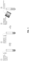
- Figure 1 shows an example schematic of an embodiment of a magnetic separation process.
- a magnetic cell separation process is referred to as an EasySep TM separation process from Stemcell Technologies.
- the magnetic separation shown in Figure 1 is an example embodiment using the EasySep TM separation protocol with a quadrupole magnet array. Reagent concentration, incubation time, and separation time vary depending on the desired separation and the strength of the magnet used.
- a cell suspension is provided in a container such as the tube shown in Figure 1 .
- containers such as a vial, a Petri dish, a bottle, a deformable container (e.g. a bag), or a multi-well micro-plate may be used.
- multi-well microplates different microplate configurations may be used, such as a 6-well plate, a 12-well plate, a 24-well plate, a 96-well micro-plate, a 384-well micro-plate, and a 1536-well micro-plate.
- the cell suspension may include a plurality of cells of interest and a plurality of undesired cells.
- a plurality of magnetic linking particles are introduced (i.e. added) to the cell suspension.
- the magnetic linking particles can be selected to link with one or more subpopulations of cells in the cell suspension such that the cells in that subpopulation, once linked with the magnetic linking particles, are magnetically susceptible.
- These linked particles may be referred to as a plurality of magnetically linked cell particles or magnetically linked particles.
- the cell suspension and the magnetic linking particles may be incubated to allow the magnetically linked particles to form.
- the plurality of magnetic linking particles may be selected to link with the cells of interest (i.e. in the case of a positive selection method). In other cases, the plurality of magnetic linking particles may be selected to link with the undesired cells (i.e. in the case of a negative selection method).
- the container may then be positioned in close proximity to a magnet array as disclosed herein.
- the container may be positioned adjacent to a surface of the magnet array.
- the container may be guided into a position near the surface of the magnet array by guide elements provided by the magnet array and/or a housing for the magnet array.
- the container may be positioned within a receiving area provided by the housing for a quadrupole magnet array.
- the guide elements may include a wall or walls that guide the container into the receiving area, e.g. by being shaped to accommodate the container in the receiving area.
- the container may be positioned in proximity to the array surface of the two-dimensional magnet array.
- the two-dimensional array may be provided as a plate magnet.
- the container may then be placed on a surface proximate the array surface (e.g. the array surface itself or a container receiving surface adjacent/just above the array surface).
- a container receiving surface is shown in Figure 5B .
- the container may be positioned in a receiving area proximate to the array surface of one or more two-dimensional magnet arrays.
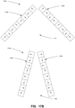
- Some examples of receiving areas are shown in Figures 13 , 14 , 16 , 17A and 17B .
- the container comprising the magnetically linked targets and unlinked targets may be left to incubate in proximity to the surface of the magnet array (e.g. in the receiving area).
- the magnetic field generated by the magnet array may attract the magnetically linked targets and magnetic particles to the container surface proximate the magnet array.
- the remaining, unlinked, targets may then be removed from the container e.g. by aspiration, pour-off, etc. As the unlinked targets are aspirated or poured off, the magnetically linked targets can be retained in the original container because of the magnetic field exerted by the magnet array.
- the unlinked targets may be removed from the suspension, e.g. through an outlet positioned adjacent the surface of the magnet array.
- This may be useful, for instance, in magnetic separations processes involving a flowing cell suspension.
- a suspension including magnetically labelled cells may be allowed to flow into a container positioned adjacent the surface of the magnet array.
- the magnetically labelled cells may be removed from the flowing suspension as they pass the magnetic array and the unlinked targets may be allowed to continue to flow out of the flow cell.
- the performance of a cell separation can be measured based on purity of the sample and the recovery of target cells after separation.
- the average magnetic field gradient on the cells should be large.
- the separation performance may depend on the strength of the magnet, the shape of the container holding the cell suspension, and the processed sample volume.
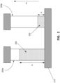
- Figure 2 shows an example of the maximum process volume height, z 1 , and the capture volume height, z 2 for an example plate magnet system.
- a container 200 is positioned adjacent a surface of the plate magnet 210.
- the container 200a is shown with the initial processed sample volume 220, including a first plurality of magnetically linked targets, a second plurality of unlinked targets, and a third plurality of unlinked magnetic particles.
- the processed sample volume 220 corresponds to the volume in container 200 after magnetic particles have been added and the suspension is allowed to incubate, but prior to the unlinked targets being removed.
- the container 200b is shown containing a capture volume 230, which corresponds to the amount of volume retained in the tube after aspiration of unlinked targets (i.e. the volume of the suspension that remains in container 200 after the unlinked targets are removed).
- the separation distance is the difference between the maximum height, z 1 , of the process volume 220 and the height, z 2 of the capture volume 230.
- magnetic arrays are formed using a plurality of magnetic elements as sources of magnetic fields.
- Electromagnets and permanent magnets are examples of sources of magnetic fields that may be used as the magnetic elements in various embodiments described herein.
- Electromagnets generally require a continuous supply of electrical energy to induce a magnetic field.
- a large current is often required.
- a large current may cause heating of the sample and/or pose safety concerns.
- Permanent magnets can generate magnetic fields passively. Advancements in permanent magnet technology may provide strong magnetic fields of 1T over volumes that may be relevant for cell separation methods (see, for example, M. Zborowski, Magnetic Cell Separation, Amsterdam: Elsevier, 2008 ). As a result, permanent magnets may provide a simple, affordable alternative for magnetic separation applications as compared to electromagnets in some embodiments. Permanent magnets can be arranged in different configurations so that field components from the permanent magnets add algebraically at a point in space. This property is called superposition and can be used to produce strong local fields and high gradients.
- plate-type magnets typically use an array of alternating north and south magnetic elements (referred to herein as a Dexter Design). This configuration creates interpolar gaps that fringe the magnetic field, generating a large field gradient.
- An example of the magnetic field lines 300 of an interpolar gap between a North magnetic element 305 and a South magnetic element 310 are shown in Figure 3A .
- a quadrupole circular arrangement 320 of magnetic elements 325 and 330 may be used as shown in Figure 3B .
- the quadrupole configuration 320 may provide a large magnetic field due to minimal loss of stray fields.
- the quadrupole configuration 320 may also provide a large field gradient because the field is large at the surface and cancels out to zero at the center 335 of the quadrupole magnetic arrangement 320.
- the alternating north south arrangement 300 for planar magnet arrays may have some drawbacks.
- One potential disadvantage of the alternating N/S configuration 300 is that the interpolar gaps may need to be carefully arranged such that they fall precisely under the wells (i.e. under container units) that are to be processed. Wells/containers that are not aligned over the interpolar gap may not experience the full magnetic gradient. As a result, magnetic separations in nonaligned wells may be inferior to magnetic separations in wells/containers falling directly above an interpolar gap. This may result in a different magnetic array being required for each different container unit geometry (e.g. for different multiwell plate geometry). This may also introduce the potential for the alignment of containers on the magnetic array to significantly impact magnetic separation performance.
- a Halbach array 350 seen in Figure 3C , has a rotating 90° pattern of magnetic elements 355a-355e.
- the Halbach array 350 uses the principle of superposition to amplify the magnetic field on one side while cancelling out the field on the other side, as illustrated in Figure 3D .
- the magnetic field 360 induced by magnetic elements 355a, 355c, and 355e is superposed with the magnetic field 365 induced by magnetic elements 355b and 355d to generate the magnetic field 370.
- embodiments using a Halbach array 350 may enable a more uniform magnetic field to be provided for a container size of interest than other magnet configurations.
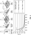
- Halbach arrays have been used in a variety of different magnetic configurations, such as a Super Halbach (SH) configuration and a Hyper Halbach (HH) configuration.
- SH Super Halbach
- HH Hyper Halbach
- the plots illustrated in Figure 4 suggest that the HH configuration produces the relatively strongest magnetic field and steepest gradient, followed by a single Halbach configuration, and alternating magnet (i.e. North South) configuration.
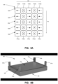
- the magnet array 500 is an example embodiment of a two-dimensional magnetic array that may be described as a linear Halbach array.
- the magnet array 500 includes a plurality of magnetic elements 510 arranged to define a two-dimensional magnetic array.
- the two-dimensional magnetic array includes a plurality of magnetic elements 510 extending along a first dimension 505 (also referred to as a row direction) and a plurality of magnetic elements 510 extending along a second dimension 515 (also referred to as a column direction).
- the plurality of magnetic elements 510 are arranged into a plurality of one-dimensional magnetic arrays 520.
- Each magnetic array 520 includes a plurality of magnetic elements 510 positioned adjacent one another extending in the direction of the first dimension 505 (i.e. to define a row of the array 500).
- the plurality of magnetic elements 510 in each one-dimensional magnetic array 520 are oriented to define a Halbach array such as the Halbach array shown in Figure 3C and described herein above.
- the one-dimensional magnetic array 520a includes magnetic elements 510aa, 510ab, 510ac, 510ad, and 510ae.
- the orientation of magnetic elements 510aa, 510ab, 510ac, 510ad, and 510ae are rotated 90 degrees with respect to each adjacent magnetic element in the same one-dimensional magnetic array 520a.
- the one-dimensional magnetic array 520e includes magnetic elements 510ea, 510eb, 510ec, 510ed, and 510ee.
- the orientation of magnetic elements 510ea, 510eb, 510ec, 510ed, and 510ee are rotated 90 degrees with respect to each adjacent magnetic element in the same one-dimensional magnetic array 520e.
- the magnetic elements 510 define an array surface of the magnetic array 500.
- the array surface is facing out from the page.
- the magnetic elements 510 are arranged such that the magnetic fields defined by the plurality of magnetic elements 510 attract magnetically susceptible particles towards the array surface.
- each one-dimensional magnetic array 520 has the same configuration and orientation of magnetic elements 510 as each of the other one-dimensional magnetic array 520. That is, each magnetic element 510 in array 500 has the same magnetic field orientation as each magnetic element that is adjacent to it in the direction of the second dimension 515 (i.e. each magnetic element 510 in a column has the same orientation).
- the magnetic elements 510 each have the same element size.
- the size and shape of the magnetic elements in the magnetic array 500 may be varied and/or tuned based on the overall size of the array.
- the size of magnetic elements 510 may vary between adjacent Halbach arrays 520 that still define magnetic fields oriented in the same direction at the surface of the array 500.
- the two-dimensional array 500 is substantially rectangular. In other embodiments, arrays may be configured into different two-dimensional configurations. In some cases, the shape of the magnetic elements may be adjusted to provide different shaped linear Halbach arrays.
- the surface of the array 500 may be substantially planar. In alternative embodiments, the surface of the array 500 need not be planar.
- the surface of the array 500 may be shaped to conform to the shape of the container that is to be used with the magnetic separation apparatus.
- the surface of the array 500 may be curved in some examples. This may facilitate cell separation with containers that may also be curved such as bags or other deformable containers.
- Embodiments described herein provide a magnetic separation apparatus.
- the magnetic separation apparatus may be used with a container configured to contain a plurality of targets.
- the plurality of targets can include desired cells/cells of interest and undesired cells, or DNA, RNA, or protein(s).
- the plurality of targets may be linked with a plurality of magnetically susceptible particles to provide magnetically linked targets that are magnetically susceptible.
- the magnetically linked targets may be magnetically susceptible particles.
- the magnetically linked targets may be generated, for instance, by linking targets (e.g. desired cells in the case of a positive selection technique or undesired cells in the case of a negative selection technique) and magnetic particles to create a magnetically linked target complex (or linked particles/cells) that includes the targets and magnetic particles.
- the apparatus may include a plurality of magnetic elements arranged to define a two-dimensional magnetic array.
- the magnetic array 500 shown in Figure 5A and discussed above may be used as the magnetic array in the magnetic separation apparatus.
- the magnetic elements can be arranged adjacent to each other defining a rectangular array having at least one row and at least one column.
- the rectangular magnetic array may typically include a plurality of rows and a plurality of columns (as in the example of array 500). In other embodiments, the magnetic array need not be rectangular.
- each row can be arranged so as to define a first order Halbach array.
- Each row of magnets can be arranged adjacent to one another such that the magnetic fields of each first order Halbach array are oriented in the same direction.
- the rectangular magnetic array can define a substantially planar magnetic plate.
- each row of magnets in the substantially planar magnetic plate may provide substantially the same magnetic field.
- the magnets in a first row of the rectangular array can have respective magnetic fields arranged so as to define a first order Halbach array. Proceeding in a column direction of the array, respective magnetic fields of magnets in each of a second and succeeding row of the array can be oriented in the same direction as respective magnetic fields of the magnets in any immediately preceding row.
- the container may be a multi-well micro-plate in some embodiments.
- the multi-well micro-plate may include at least one of an isolated tube or single well, a 6-well plate, a 12-well plate, a 24-well plate, a 96-well micro-plate, a 384-well micro-plate, and a 1536-well micro-plate.
- the container may also include at least one of a tube, a vial, a Petri dish, a bag (e.g. a soft-walled container of any shape) and a bottle for example.
- a container such as a tube or bag having an inlet or an outlet, or both, may allow a suspension comprising targets to flow while the magnetic separation method is performed.
- the suspension may be substantially static within the container.
- the magnets used in the magnetic separation apparatus may take the form of permanent magnets. This may avoid heating the sample being separated. This may also avoid safety concerns that may be associated with using currents to induce the magnetic fields.
- the magnets may be electromagnets. This may also the magnetic fields of the magnets to be controlled (e.g. activated and deactivated) connecting or disconnecting a current supply.
- the magnets may be supported by or within (i.e. enclosed by) a housing in the magnetic separation apparatus such as the housing 550 shown in FIG. 5B discussed below.
- the housing may facilitate construction and operation of the magnetic array.
- a housing 550 may be used to support a two-dimensional magnet array, such as magnet array 500 shown in Figure 5A .
- the magnet array may be enclosed within the housing 550.
- the housing 550 may act as a protective housing around the magnet array 500.
- the housing 550 may also retain the magnetic elements of the magnet array 500 in place.
- the housing 550 may include a housing base 560.
- the interior of the housing base 560 may define a frame for receiving the magnetic elements.
- the frame may include a plurality of channels and grooves that define the shape of a two-dimensional array.
- the housing base 560 may include walls defining the channels and grooves of the frame.
- the housing base 560 may also include sidewalls 565 extending upward from the housing base 560. In some cases, the sidewalls 565 may serve to define an outer portion of the channels in the housing base 560.
- Each channel may extend substantially across the array along a first dimension.
- Each channel may include a plurality of grooves corresponding to the positions along the first dimension at which magnetic elements may be positioned.
- the magnetic elements of a magnet array can be positioned within the channels and grooves of the housing base 560. Individual magnetic elements may be secured in place within the corresponding channel and groove location. For example, a magnetic element may be secured to the housing base 560 using a set screw.
- the housing 550 may also include a housing cover 555 that may be mounted to cover the magnetic elements, and may or may not be magnetic, ferromagnetic, or magnetizable itself. In general, a thin non-ferromagnetic material is desired since it does not disturb the magnetic field. However, a ferromagnetic cover with a different surface profile may have positive effects on magnetic separation.
- the cover 555 may also provide additional support to maintain the magnetic elements in place.
- the housing cover 555 may also include a container receiving surface 580 adjacent the array surface of the magnet array supported by the housing. The container receiving surface 580 may be shaped to support a container for use in magnetic separation processes.
- the housing base 560 may be thicker than the housing cover 555. This may allow the housing base 560 to provide structural integrity for the housing 550.
- the housing cover 555 may be thin to minimize interference with the magnetic fields of the magnet array and provide a maximum magnetic field strength for a container positioned adjacent to, or on, the container receiving surface 580 of the housing cover 555.
- the housing 550 may facilitate manufacturing of the two-dimensional magnetic array, because the linear Halbach array structure can be an unstable magnetic configuration with adjacent magnetic elements repelling one another.
- the magnetic elements may be formed of brittle materials, such as ceramic elements. In such cases, the housing 550 may be preferred to secure the magnetic elements in place while ensuring that the ceramic elements are not damaged.
- the housing 550 may be omitted if an alternative method is used to fix the magnetic elements adjacent one another (e.g. glue or connectors between adjacent magnets).
- the magnetic elements may be shaped to interlock with one another (see e.g. Figure 15 ). In some cases, this may permit more brittle magnetic elements (e.g. ceramic elements) to be used without requiring the housing.
- brittle magnetic elements e.g. ceramic elements
- the housing 550 may also include guide elements 570a-570d.
- the guide elements 570 may be used to guide or direct a container toward a container receiving surface 580 adjacent, or provided by, the top cover 555 of the housing 550.
- the guide elements 570 may also retain the container or container unit proximate the surface of the magnet array.
- the guide elements 570 may include guide members that extend from the housing 550.
- the guide members may extend from the top cover 555 of housing 550, the sidewalls 565, and/or the housing base 560.
- the guide members may be shaped and positioned to correspond to the shape of a container used in a magnetic separation process.
- the guide elements 570 may include guide members extending from the surface of the top cover of the housing at each corner of the housing 550.
- the guide elements 570 may include guide channels 575 shaped to engage a container and/or a container unit that holds a plurality of containers.
- the guide elements may retain a multi-well container unit near the container receiving surface 580. This may facilitate multiple individual containers held within the multi-well container unit being concurrently positioned above, and proximate to, the container receiving surface 580.
- the guide elements 570 may also elevate the top cover 555 of the housing 550 from another surface if the magnetic separation apparatus is positioned with the top cover 555 facing a surface. This may facilitate removing the magnetic separation apparatus from magnetically susceptible surfaces, such as metal surfaces, by enabling the magnetic separation apparatus to be pried off the surfaces.
- the guide members may also operate as a safety feature to ensure that a user's hand is not crushed by the magnetic separation apparatus being attracted to a surface or to another magnetic separation apparatus.
- the magnets in the array may be sized and arranged to provide a desired balance of field uniformity, field strength and magnetic field intensity decay rate (i.e. the useful depth in which a cell separation using magnetic particles may be achieved) for the container units and sizes of interest in various embodiments.
- the magnets may also be arranged to achieve a desired balance between field gradient and field penetration distance allowing for larger depth of magnetic separation volume for the container units and sizes of interest in various embodiments.
- Embodiments of the magnetic separation apparatuses and systems described herein may also combine a plurality of two-dimensional magnetic arrays in a modular manner.
- the two-dimensional magnetic arrays may be assembled into larger arrays by combining individual two-dimensional magnetic arrays into larger two-dimensional magnetic arrays. This may allow the magnetic separation apparatus to be used with containers of different size.
- the two-dimensional magnet arrays may include columns of magnetic elements having the same orientation, while the rows define Halbach arrays. This configuration may facilitate a modular construction in which multiple two-dimensional magnet arrays can be positioned side-by-side with the magnetic fields oriented and facing in the same direction. As the columns have a repeating pattern/sequence of magnetic elements (e.g. the same element throughout the column), the columns can be easily extended across multiple two-dimensional magnet arrays.
- individual two-dimensional magnetic arrays can be arranged back to back so that separations can be performed on 2 sets of samples, such as in a tube rack configuration.
- This may facilitate rapid, automated processing methods, such as those involving automated pipetting systems.
- containers such as test tubes may be positioned on either side of the back to back two-dimensional magnetic arrays.
- Samples can be transferred to the tubes on either side, and a magnetic separation process can be performed on those samples substantially concurrently. Because the linear Halbach array results in a minimal magnetic field on the side opposite the array surface (as shown in Figure 3D above), minimal interference may occur in this back-to-back arrangement.
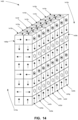
- the magnetic separation apparatus 1400 includes a first two-dimensional magnet array 1405a and a second two-dimensional magnet array 1405b.
- the first two-dimensional magnet array 1405a includes a plurality of one-dimensional magnetic arrays 1415a-1415h.
- the second two-dimensional magnet array 1405b includes a plurality of one-dimensional magnetic arrays 1425a-1425h.
- the apparatus 1400 includes a first receiving area 1410a corresponding to the first two-dimensional magnet array 1405a.
- the apparatus 1400 also includes a second receiving area 1410b corresponding to the second two-dimensional magnet array 1405b. This may allow containers to be positioned on either side of the apparatus 1400 for magnetic cell separation.
- the pair of two-dimensional magnet arrays 1405a and 1405b are positioned in a back-to-back arrangement. That is, the magnetic field generated by the first two-dimensional magnet array 1405a is oriented in the direction opposite to the magnetic field generated by the second two-dimensional magnet array 1405b.
- Containers may be used on either side, or both, of the back-to-back arrays 1405a and 1405b to perform magnetic separation methods.
- the magnetic separation apparatus 1400 may allow each of the first two-dimensional magnet array 1405a and the second two-dimensional magnet array 1405b to perform magnetic cell separation substantially simultaneously with containers positioned on opposite sides of the apparatus 1400.
- 2 or more of the two-dimensional magnetic arrays may be arranged in a facing arrangement (or partial facing arrangement).
- 2 or more individual two-dimensional magnetic arrays can be arranged in a parallel manner with one or more containers positioned or sandwiched between planar arrays for magnetic separation.
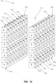
- the magnetic separation system 1300 includes a plurality of two-dimensional magnet arrays, including the first two-dimensional magnet array 1305a and the second two-dimensional magnet array 1305b.
- the two-dimensional magnet arrays 1305a and 1305b may be generally similar to two-dimensional magnet array 500 shown in Figure 5 .
- the first two-dimensional magnet array 1305a includes a plurality of one-dimensional magnetic arrays 1315a-1315h.
- the magnetic elements in each of the one-dimensional magnetic arrays 1315a-1315h are oriented to define a Halbach array.
- the magnetic fields of each Halbach array 1315a-1315h are oriented in the same direction in the first two-dimensional magnet array 1305a.
- the magnetic fields of magnetic elements laterally adjacent to one another, but in different Halbach arrays 1315 are also oriented in the same direction.
- the second two-dimensional magnet array 1305b includes a plurality of one-dimensional magnetic arrays 1325a-1325h.
- the magnetic elements in each of the one-dimensional magnetic arrays 1325a-1325h are oriented to define a Halbach array.
- the magnetic fields of each Halbach array 1325a-1325h are oriented in the same direction in the first two-dimensional magnet array 1305b.
- the magnetic fields of magnetic elements laterally adjacent to one another, but in different Halbach arrays 1325 are also oriented in the same direction. In other embodiments, the magnetic fields of laterally adjacent magnetic elements need not be in the same direction as shown in Figures 17A and 17B .
- the pair of two-dimensional magnet array 1305a and 1305b are provided in a facing arrangement. That is, the magnetic field from the first two-dimensional magnet array 1305a is oriented towards the second two-dimensional magnet array 1305b. Similarly, the magnetic field from the second two-dimensional magnet array 1305b is oriented towards the first two-dimensional magnetic array 1305 a.
- the System 1300 includes a receiving area 1310.
- the receiving area is configured to receive a container.
- a cell suspension within the container can be magnetically separated using the magnetic fields induced by the pair of two-dimensional magnet array 1305a and 1305b.
- the receiving area 1310 may be configured to receive a test tubes, dishes or flasks or tray(s) of test tubes, dishes or flasks.
- the receiving area 1310 may positioned to allow a cell suspension to flow therethrough, allowing magnetically susceptible particles to be removed from the flowing suspension.
- the first two-dimensional magnet array 1305a and the second two-dimensional magnet array 1305b are parallel to one another.
- the strength of the magnetic fields of the first two-dimensional magnet array 1305a and the second two-dimensional magnet array 1305b define a magnetic strength midpoint plane at a position within receiving area 1310 of the first two-dimensional magnet array 1305a and the second two-dimensional magnet array 1305b.
- the magnetic strength midpoint plane may correspond to the geometric midpoint, for instance, where the magnetic fields of the first two-dimensional magnet array 1305a and the second two-dimensional magnet array 1305b are identical. In other cases, where the magnetic field strength varies, the magnetic strength midpoint plane may not be positioned at the geometric midpoint.
- the magnetic fields of the first two-dimensional magnet array 1305a and the second two-dimensional magnet array 1305b can be selected to provide a magnetic field strength minimum substantially along the plane defining the magnetic strength midpoint.
- the receiving area 1310 may be configured to direct the container or containers to the magnetic strength midpoint plane. This may facilitate magnetic separation by providing a large field gradient between the first two-dimensional magnet array 1305a and the second two-dimensional magnet array 1305b.
- the orientation between parallel planar arrays can be configured such that a plane defining a magnetic field strength minimum is obtained near the plane defining the magnetic field strength midpoint between the parallel planar Halbach arrays.
- the magnetic field strength midpoint may not correspond directly to the geometric midpoint between the two-dimensional magnetic arrays, for example where the magnetic field strength of the respective two-dimensional magnetic arrays is different. This may increase the magnetic field gradient as one moves away from the bisecting magnetic field minimum plane.
- Magnetic separation apparatus 1750a includes a pair of two-dimensional magnet arrays 1755a and 1755b in a partially facing arrangement (also referred to as an acute angular relationship).
- a receiving area 1760 for a container is positioned in a region in front of both two-dimensional magnet arrays 1755a and 1755b.
- the magnetic fields of both two-dimensional magnet arrays 1755a and 1755b can thus overlap, at least partially, to attract targets in a container in the receiving area 1760.
- Magnetic separation apparatus 1700b is similar to apparatus 1700a in that it includes a pair of two-dimensional magnet arrays 1705a and 1705b' in a perpendicular arrangement. However, in magnetic separation apparatus 1700b the orientation of the two-dimensional magnet array 1705b' has been rotated with respect to the orientation of two-dimensional magnet array 1705b. As a result, the magnetic field interacting with a container in the receiving area 1710 would be different for magnetic separation apparatus 1700b as compared to magnetic separation apparatus 1700a.
- magnetic separation apparatus 1750b is similar to magnet separation apparatus 1750a except that the magnetic field of magnet array 1755b' is rotated with respect to the magnetic field of magnet array 1755b.
- the magnetic field interacting with a container in the receiving area 1760 would be different for magnetic separation apparatus 1750b as compared to magnetic separation apparatus 1750a.
- the embodiments described herein may provide a substantially universal plate magnet that can be used for automation applications that can process small (e.g. 1 micro-Litre) to large volumes (> 50 mL) in a reasonable time frame.
- small e.g. 1 micro-Litre
- large volumes > 50 mL
- the size and shape of the magnetic blocks in the magnetic array can be varied and tuned dependent on the overall size of the array.
- the magnetic elements may be rectangular (and not cubic) in shape or other shapes to provide the desired magnetic field distribution and uniformity.
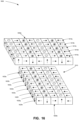
- a first one-dimensional Halbach array 1500a includes a first plurality of magnetic elements 1510a-1510i.
- a second one-dimensional Halbach array 1500b includes a second plurality of magnetic elements 1520a-1520i.
- the magnetic fields of the magnetic elements 1510a-1510i are oriented to define the Halbach array 1500a.
- the magnetic elements 1510 do not have a constant element size. Rather, the size of the magnetic elements 1510 varies throughout the Halbach array 1500a.
- the size of the magnetic elements 1510 varies in a repeating pattern, with each second magnetic element 1510 having the same size.
- the magnetic elements 1510 do not have a constant shape. Rather, the shape also varies with each second magnetic element 1510 having the same shape.
- magnetic elements 1510a, 1510c, 1510e, 1510g and 1510i have the same shape and size as one another.
- Magnetic elements 1510b, 1510d, 1510f and 1510h have the same shape and size as one another, but different from magnetic elements 1510a, 1510c, 1510e, 1510g and 1510i.
- Halbach array 1500b also illustrates an example magnetic array using varying element size.
- the magnetic elements 1520b, 1520d, 1520f and 1520h have generally the same shape and size of magnetic elements 1510b, 1510d, 1510f and 1510h from array 1500a.
- the magnetic elements 1520a, 1520c, 1520e, 1520g and 1520i are smaller than the magnetic elements 1510a, 1510c, 1510e, 1510g and 1510i of array 1500a.
- the Halbach arrays 1500a and 1500b also illustrate an example of one-dimensional magnetic arrays with interlocking magnetic elements. This may provide additional structural support between the magnetic elements in the arrays.
- embodiments of the LH arrays described herein may provide both a strong magnetic field gradient and a very uniform field for a container unit of interest. This may enable, for example, cell separation to be carried out reproducibly for containers positioned at locations across the magnetic surface independent of the precise positioning of the sample on the surface of the magnet array.
- the magnetic field is defined by magnetic field strength, H , and magnetic field intensity, B .
- the magnetic field strength vector describes the strength of the magnetic field source and the magnetic field intensity vector describes the resulting effect on the surrounding space.
- the magnetic field strength can be labelled as the driving force or "the cause”, whereas the magnetic field intensity can be considered the coupled flux density or "the effect”.
- the magnetic field intensity is proportional to the magnetic field strength as shown in equation (3).
- B ⁇ 0 H
- a magnetic field can be visualized using magnetic field lines.
- the magnetic field lines are tangent everywhere to the magnetic field strength and magnetic field intensity vectors.
- the presence of matter changes the relationship between magnetic field strength and magnetic field intensity.
- the magnetic field intensity in matter is given by equation (4).
- Magnetization defines the density of magnetic dipole moments m in a material of volume V , as expressed in equation (5).
- Magnetic susceptibility is often very small for biological material such as cells and their medium. This is because cells are composed of mostly water which is diamagnetic. Water has a very small, negative magnetic susceptibility on the order of 10 -6 . Ferromagnetic materials that may be used in magnetic cell separation can have magnetic susceptibilities on the order of 10 -1 . Thus, labelling target cells with magnetic particles can drastically increase the magnetic susceptibility of the target cell compared to its surroundings.
- Equation (10) The total magnetic force on a magnetically labelled cell is given by equation (10).
- F m n p / c V p ⁇ ⁇ 0 1 + ⁇ B ⁇ ⁇ B
- n p/c the number of particles per cell
- V p the volume of a single magnetic particle
- the magnetic force on a labelled cell can be characterized by the magnetic particle properties (which are assumed constant), and the term ( B ⁇ V ) B , which is the differentiation of the magnetic field intensity vector, B , with respect to its self.
- This term is called the magnetic force density and is defined by the equation (11).
- B ⁇ ⁇ B B x ⁇ B x ⁇ x + B y ⁇ B x ⁇ y + B z ⁇ B x ⁇ z ⁇ ⁇ B x ⁇ B y ⁇ x + B y ⁇ B y ⁇ y + B z ⁇ B y ⁇ z j ⁇ B x ⁇ B z ⁇ x + B y ⁇ B z ⁇ y + B z ⁇ B z ⁇ z k ⁇
- the above formula shows that the magnetic force on a cell is a function of the magnetic field intensity and the magnetic field intensity gradient.
- the path of a labelled cell in an external magnetic field may not be intuitive, as it does not follow the magnetic field lines.
- the cell follows magnetic path lines defined by the magnetic force field defined above.
- the magnetic path lines are tangent everywhere to the magnetic force field.
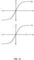
- Magnetic nanoparticles typically used in cell separation are superparamagnetic.
- the magnetization curve of superparamagnetic particles can be seen in Figure 12.
- Figure 12 shows that the magnetic particle can either be in a linear superparamagnetic region where the magnetization is proportional to the magnetic field intensity or a saturated magnetic region where the magnetization remains constant.
- This can be mathematically represented by a term called effective susceptibility, ⁇ eff , in equation (13).
- the magnetic force on the target may depend on if the particles are in the linear or saturated superparamagnetic region. This can be represented in equation form by substituting the piecewise effective susceptibility equation (13) into equation (14), yielding equation (15). Simplifying equation (15) to a one-dimensional case gives equation (16).
- Equation (16) shows that, in the linear superparamagnetic region, the magnetic force is a product of the magnetic properties of the particles (which are constant), the magnetic field, and the magnetic field gradient. In the saturated superparamagnetic region the magnetic force is a product of the magnetic properties of the particles and the field gradient.
- the average magnetic force on the targets in a container should be large. This means that in the plate magnet system the separation performance will often depend on the hardware used, and the sample volume being processed. This is because the hardware and the process volume define the separation height range.
- the separation height range seen in Figure 2 , is the difference between the maximum process volume height, z 1 , and the capture volume height, z 2 .
- the capture volume being the amount of volume retained in the tube.
- the average magnetic force (over a given separation height range) will be derived for a uniform plate magnet system.
- the magnetic nanoparticles available from STEMCELL Technologies used to evaluate the example plate magnet embodiments saturate at a magnetic field intensity of approximately 0.5T.
- the plate magnet embodiments tested there are considerably more magnetic nanoparticles in the superparamagnetic linear region compared to the saturated region. This is because the maximum magnetic field intensity for the prototypes of the embodiments tested was around 0.5T at the surface which was found to decay exponentially with height. Therefore, the proportion of cells in the saturated region versus cells in the linear region is negligible.
- the magnetic force on the cells can be given by equation (17).
- the magnetic force can be given by equation (18).
- the magnetic particle properties and labelling conditions in the linear superparamagnetic region are represented by a constant, y, defined in equation (19).
- F m n p/c V p ⁇ eff ⁇ 0
- V p ⁇ eff ⁇ 0 m sat B sat
- the magnetic field intensity as a function of height was determined experimentally for uniform plate magnets.
- the magnetic field decay with height for a uniform plate magnet is defined by equation (20).
- ⁇ is a positive constant that represents the magnetic field at the surface of the magnet
- ⁇ is a positive constant that defines the magnetic field decay rate with height.
- Equation (11) The general magnetic force density function defined earlier in equation (11) can be simplified to equation (24) for the uniform plate magnet case.
- the magnetic force at a given height over a uniform plate magnet may be determined using equation (25).
- F m ⁇ ⁇ 2 ⁇ e ⁇ 2 ⁇ z k ⁇
- Equation (26) defines the magnetic force density magnitude (MFD) as the function fd( z ). Taking the integral of equation (26) over the separation height range and dividing by the separation height range gives equation (27), the average MFD (AVG MFD).
- the AVG MFD is proportional to the average force experienced on the cells; therefore it is directly related to the recovery rate. As a result, the inventors used the AVG MFD as a parameter for comparing the various embodiments described herein.
- a magnet be compatible with a variety of hardware.
- a flat profile of a plate magnet may allow for easy compatibility with a large range of hardware such as microplates, tubes, cell culture flasks, or bags.
- a curved or non-planar profile of the plate magnet may allow for easy compatibility with deformable containers, such as bags.
- Embodiments described herein may also be mountable onto automated cell separation instruments. Embodiments described herein can, however, also have a large average MFD over a large volume range. The MFD depends on the magnetic field at the surface, the magnetic field gradient, and the separation height range. A uniform magnetic field is preferred so that separation performance is consistent at any location and with any hardware. Some embodiments described herein may be able to process samples in a time period of 15 minutes or less.
- the recovery and final purity of targets separated using the described plate magnets may vary with hardware and process volume, however it is preferred that performance be at least equal to or greater to the performance of other magnet configurations against which the prototype embodiments were tested.
- the unit-size plate magnet should preferably have a footprint equal to the area of a standard microplate or about 0.011sq m (0.12 sq ft).
- Table 1 Design Objectives and Benchmark Values for Embodiments of the Plate Magnet Design Objective(s) Benchmark Value(s) for Example Embodiments Compatibility with a variety of hardware Microplates, tubes, flasks, bags, etc.
- Mountability RoboSep-16 Large average magnetic force over large height range Greater than or equal to the BLUE magnet available from Stemcell Technologies (although it will be variable depending on associated hardware) Uniformity of magnetic field Consistent performance Sample processing in reasonable time frame Less than or equal to 15 minutes High recovery of target cells Greater than or equal to the BLUE magnet available from Stemcell Technologies (although it will be variable depending on associated hardware) High final purity of target cells Greater than or equal to the BLUE magnet available from Stemcell Technologies (although it will be variable depending on associated hardware) Small footprint .12 sq ft ⁇ footprint ⁇ 1 sq ft Movability ⁇ 20lbs Easy to manufacture Simple and safe assembly Reasonable cost to manufacture ⁇ $400 Safe to handle Necessary safety features
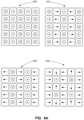
- FIG. 6A Three alternative configurations (shown in Figure 6A ) of a plate magnet were tested and evaluated using prototypes constructed by the inventors.
- the alternative configurations tested were an example of the Linear Halbach (LH) array configuration 620 similar to the array 500 described herein shown in Figure 5A above, and the Super Halbach (SH) 610 and Hyper Halbach (HH) 630 arrays mentioned above.
- Prototypes of these embodiments were evaluated against existing NS plate magnet configurations 600 (Dexter Design) available from Stemcell Technologies. Desirable parameters such as consistent cell separation performance, large average MFD (Magnetic Force Density), high final recovery, high final purity, and ease of assembly were evaluated as a means of comparison, the results of which are shown in Figures 7 and 8B-11 .
- the SH design 610 tested by the inventors had consistent separation performance, but had an AVG MFD (for typical cell separation height ranges) similar to the Dexter NS design 600. Accordingly, the cell separation performance in the SH 610 was similar to the NS 600.
- the LH embodiment 620 and HH configuration 630 tested had similar AVG MFD's (for typical cell separation height ranges) that were much greater than the NS configuration 600. This translated to the LH embodiment 620 and HH configuration 630 having similar cell separation performance in terms of final cell recovery and purity.
- the LH embodiment 620 and HH configuration 630 had recovery rates that were approximately twice that of the NS configuration 600. This resulted in higher final recoveries and purities for the LH array 620 and HH array 630 compared to the NS configuration 600.
- the LH embodiment 620 tested had a uniform magnetic field for the locations of interest, which resulted in consistent cell separation performance at all locations on the magnet.
- the HH configuration 630 tested did not show a uniform magnetic field and had a strong pole (HH H Pole) and a weak pole (HH N Pole). As a result, in the HH configuration 630 tested the cell separation performance was not consistent over all locations.
- the LH embodiment 620 also provided a simple arrangement of magnets that facilitated assembly (as described above). The LH embodiment 620 was even found to outperform the current DEXTER NS design 600 magnet despite having significantly smaller and lower grade magnets.
- a constant element size nine-by-nine array for each of the HH, LH and SH arrays were constructed using 1/4 inch cube N42 rare earth magnets.
- a top view schematic of the HH 630, LH 620 and SH 610 arrays is shown in Figures 6A along with the top view of a NS control configuration 600. The arrows point from the south pole to north pole of the magnet.
- FIG. 5B and 6B An example of a housing was used to hold the cube magnets in the desired orientation. Magnets were equally spaced apart in the X direction with 1mm ribs and in the Y direction with 1 mm plastic spacers. This may help maintain a uniform magnetic field.
- the top cover of the housing can be preferably as thin as possible (1 mm) to maximize the magnetic field at the surface.
- the housing base can have an increased thickness (3 mm) that may provide the housing with sufficient rigidity.
- a pair of housing portions i.e. a base and top cover
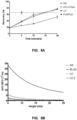
- the magnetic field decay with height was characterized for each prototype by measuring the field at different height intervals (as shown in Figure 7 ).
- the NS, SH, LH, HH, and Dexter design (a BLUE magnet from Stemcell technologies) magnets were evaluated.
- the HH configuration may not be uniform.
- the HH configuration may have strong poles, which are referred to as Hyper Poles (H Pole), and weak poles called the Null Poles (N Pole).
- the HH H Pole and HH N Pole were each tested in this experiment. Measurements were made at 0, 0.4, 0.76, 1.72, 3.46, 6.4, 9.46, 12.65 mm from the magnet housing surface. Plastic spacers were used to create the change in height because they do not interfere with the magnetic field. In this experiment three replicate measurements were made for each of the 48 conditions giving a total of 144 measurements. The results from this experiment are shown in the chart of Figure 7 .
- Table 2 The magnetic field characteristics for the various magnets tested are shown in Table 2: Table 2 - Magnetic Field Characteristics for Magnet Embodiments Magnet ⁇ (G) ⁇ STDEV(G) ⁇ (1/mm) ⁇ STDEV (1/mm) R2 BLUE 4537 17.60 0.324 0.0034 0.9994 NS 3588 9.21 0.436 0.0030 0.9998 SH 4086 13.58 0.463 0.0041 0.9997 LH 4878 15.94 0.228 0.0021 0.9994 HH H Pole 5846 8.15 0.266 0.0010 0.9999 HH N Pole 2996 24.14 0.551 0.0117 0.9974
- the magnetic field strength at the surface in decreasing order were HH H Pole, LH, DEXTER DESIGN, SH, NS and HH N Pole, which had magnitudes of 5800 G (0.58 T), 4900 G (0.49 T), 4500 G (0.45 T), 4100 G (0.41 T), 3600 G (0.36 T), and 3000 (0.3 T), respectively.
- the magnetic field decay rates in decreasing order belong to the HH N Pole, SH, NS, DEXTER DESIGN, HH H Pole, and LH, which had values of 0.55 mm -1 , 0.46 mm -1 , 0.44 mm -1 , 0.32 mm -1 , 0.27 mm -1 , and 0.23 mm -1 , respectively.
- a larger magnetic field decay rate corresponds to a steeper field gradient.
- the HH did not have a uniform field; the HH H Pole had the largest field magnitude whereas the HH N Pole had the weakest.
- the HH H Pole generated a 61% larger field compared to the NS.
- the magnetic field decay rate for the HH H Pole was 39% smaller than the NS decay rate, while the HH N Pole was 25% larger than the NS decay rate.
- the LH had the second largest field magnitude and a uniform field over all poles (other locations were not tested).
- the magnetic field magnitude was 36% larger than the NS field magnitude and the magnetic field decay rate was 48% smaller than the NS rate.
- the LH's strong initial magnetic field and shallow field gradient allows for separation of large height ranges.
- the SH had a uniform field over the poles.
- the magnetic field magnitude was only slightly larger (14%) than the NS field magnitude, and the magnetic field rate was slightly larger (5%) than the NS rate.
- the AVG MFD for this magnet is expected to be small because it has a small initial magnetic field and shallow gradient.
- Both the LH and HH H Pole magnets had larger initial magnetic fields and smaller field decay rates compared to the DEXTER DESIGN magnet.
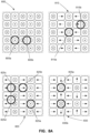
- Consistent separation performance is the driving force for a plate magnet having a uniform field. In theory, if the magnetic field is uniform, the separation performance should be consistent. Uniformity was tested for each alternative magnet configuration as well as the control magnets by performing CD3 positive cell selection separations at different locations on each magnet. If the recovery of CD3 cells was consistent from location to location the magnet was considered uniform (at least for cell separation purposes).
- the NS configuration and Dexter Design magnets 800 was tested at positions 805a and 805b.
- the SH configuration 810 was tested at positions 815a and 815b.
- the example LH embodiment 820 was tested at positions 825a-825d.
- the HH configuration 830 was tested at positions 835a and 835b.
- the PURPLE magnet (available from Stemcell Technologies) was used as control for maximum recovery.
- the Dexter and NS magnets have four independent (non-repeating locations), SH and LH have six independent locations, and the HH has 12 independent locations.
- For the plate magnets 2 mL vials were used as they could be easily placed directly over a desired location.
- the process volume used was a 0.5 mL capture volume and 0.1 mL was left behind. This means, theoretically, the baseline recovery should be 20%.
- the negative fraction was removed using aspiration with micropipette.
- the PURPLE magnet used a 5 mL tube and had a process volume of 2 mL. In this experiment, there were 12 conditions with three replicates, for a total of 36 separations. The separations were run in a random block design. The results from this experiment can be seen in Figure 8B .
- the NS, SH, and LH were found to have consistent recoveries, indicating they have uniform fields.
- the average LH recovery was 70.21%, which was 59% more than the NS recovery of 44.28%.
- the average HH H Pole recovery was 75.35%, which 70% more than the NS recovery.
- These recoveries are larger than the average Dexter magnet design with a recovery of 61.64%.
- the SH and the HH N Pole had average recoveries of 39.26% and 44.76%, respectively, which were both lower than the average NS recovery.
- the SH recoveries were lower than the NS most likely because the field magnitude is the same, but the gradient is slightly shallower.
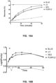
- the recovery as a function of time was characterized for each prototype of the alternative magnet embodiments. This may provide a better understanding of how recovery varies with time for each plate magnet system.
- the separation was a CD3 positive cell selection, with a 0.5 mL process volume, and 0.1 mL capture volume. Again, the theoretical baseline recovery is 20%. The maximum recovery was found by completing a 2 mL PURPLE magnet separation.
- the different plate magnets used were the NS, LH, and HH, and all separations were done on the P1 location (from last experiment). Each magnet had separations completed at time intervals of 0, 5, 10, and 20 minutes. Again, 2 mL vials were used as they could be easily placed directly over the desired location.
- the LH and HH H Pole had similar recovery rates. This is because the LH and HH H Pole had similar AVG MFD over the separation height range for the current experimental setup.
- the 2 mL vial sits 5 mm above the magnet surface; therefore the HH H Pole with its slightly steeper field gradient loses the advantage of its higher initial magnetic field.
- the recovery rates for the LH and HH H Pole are about twice the recovery rate of the NS.
- the recovery rates of the LH and Dexter magnets were compared head to head, and the cell sedimentation rate was quantified.
- the sedimentation of non-target cells can lead to a decrease in final purity.
- the separation was a CD3 positive cell selection, with a 1 mL process volume, and 0.1 mL capture volume. Therefore, the baseline recovery is 10%.
- the maximum recovery was found by completing a 2 mL PURPLE magnet separation.
- the different plate magnets used were the LH and the Dexter design, and all separations were done on the P1 location (described above). Each magnet had separations completed at time intervals of 0, 3, 5, 8, 10, 15, 25, 40 and 60 minutes.
- a sedimentation condition (SED) that was not placed on a magnet was also processed at the same time intervals. Again, 2 mL vials were used as they could be easily placed directly over the desired location. In this experiment, there were 26 conditions with two replicates, for a total of 52 separations. Since there were so many separations the two replicates for each condition were mixed prior to flow cytometry analysis. This provides a manual average of the replicates. The separations were run in a random block design. The recovery and change in purity odds ratio versus time results from this experiment can be seen in Figures 10A (recovery versus time for LH, BLUE, and SED) and 10B (purity change in odds ratio versus time for LH, BLUE and SED).
- the prototype LH embodiments used 1/4", N42 grade, rare earth, cube magnets as the magnetic elements.
- a further embodiment of the LH design (referred to as LH2) may employ 1/2", N52 grade, rare earth, cube magnets compared to the 1/4", N42 grade, rare earth, cube magnets as the magnetic elements.
- the AVG MFD was estimated for the LH2 embodiment over a range of process volume heights and a constant capture volume height.
- the AVG MFD was also simulated for the NS, Dexter, and LH for contrast.
- Figure 11 shows the AVG MFD as a function of process volume height for the NS configuration, Dexter configuration, and the LH and LH2 embodiments.
- the capture volume height has been set to 4.99 mm and the process volume height varies from 5 mm to 25 mm.
- the LH2 embodiment is expected to produce a much stronger average magnetic force on the cells compared to the DEXTER DESIGN magnet because of its larger AVG MFD. This suggests that the LH2 design will be much stronger than the current Dexter design, therefore it should have the capabilities to process a large separation height range (potentially up to an inch). Depending on the hardware used, the LH2 should be able to process small to extra-large process volumes.
- the linear Halbach array is not a stable configuration of the magnet elements.
- a suitable housing may be required to hold the elements of the linear Halbach array in place. Stronger magnetic elements may cause large internal stresses in the housing; therefore a strong material may be required for the housing.
- Aluminum is one example of a suitable housing material because it has a large strength to weight ratio, and is a non-magnetic material. By contrast, while steel is very strong, it is ferromagnetic and may disturb the magnetic field.
- set screws may be used to secure magnetic elements in place.
- Outer posts e.g. guide elements such as four outer posts extending about a 1/2" from the surface of the housing may be used as a safety precaution. These posts may stop the magnet from getting too close to large ferromagnetic objects. This may also protect users from getting their hands crushed. The posts can be used to protect users from large ferromagnetic objects. Small ferromagnetic objects may still have access to the magnet surface, so users should handle the magnet with care. The thickness of the top plate/cover may be minimized in order to maximize the AVG MFD.
- the size and shape of the magnetic elements in the linear Halbach array can be varied and tuned dependent on the overall size of the array. For example, in an array of 85 mm x 130 mm (standard ANSI plate dimensions) alternating blocks of small cubic magnet elements can be assembled with larger (double size) blocks to reduce the boundary effects of a finite linear Halbach array (see e.g. Figure 15 ). Designs can be created that, while sacrificing magnetic strength, result in an overall more uniform magnetic field across the surface of the array.
- Linear Halbach Arrays can be optimized to create both a very strong magnetic field gradient and a uniform field that enables, for example, cell separation to be carried out reproducibly across the magnetic surface independent of the precise positioning of the sample on the surface of the magnet array.
- variable sized magnetic elements may be used in the array to improve field uniformity.
Landscapes
- Health & Medical Sciences (AREA)
- Life Sciences & Earth Sciences (AREA)
- Engineering & Computer Science (AREA)
- Chemical & Material Sciences (AREA)
- Immunology (AREA)
- Biomedical Technology (AREA)
- Molecular Biology (AREA)
- Hematology (AREA)
- Urology & Nephrology (AREA)
- Biochemistry (AREA)
- General Health & Medical Sciences (AREA)
- Organic Chemistry (AREA)
- Microbiology (AREA)
- Biotechnology (AREA)
- Genetics & Genomics (AREA)
- Analytical Chemistry (AREA)
- Zoology (AREA)
- Medicinal Chemistry (AREA)
- Wood Science & Technology (AREA)
- Bioinformatics & Cheminformatics (AREA)
- Cell Biology (AREA)
- Food Science & Technology (AREA)
- Pathology (AREA)
- General Physics & Mathematics (AREA)
- Physics & Mathematics (AREA)
- General Engineering & Computer Science (AREA)
- Proteomics, Peptides & Aminoacids (AREA)
- Biophysics (AREA)
- Apparatus Associated With Microorganisms And Enzymes (AREA)
- Liquid Crystal (AREA)
- Audible-Bandwidth Dynamoelectric Transducers Other Than Pickups (AREA)
Applications Claiming Priority (3)
| Application Number | Priority Date | Filing Date | Title |
|---|---|---|---|
| US201662332578P | 2016-05-06 | 2016-05-06 | |
| PCT/CA2017/050554 WO2017190254A1 (en) | 2016-05-06 | 2017-05-05 | Plate magnet |
| EP17792345.5A EP3452590B1 (en) | 2016-05-06 | 2017-05-05 | Plate magnet |
Related Parent Applications (2)
| Application Number | Title | Priority Date | Filing Date |
|---|---|---|---|
| EP17792345.5A Division-Into EP3452590B1 (en) | 2016-05-06 | 2017-05-05 | Plate magnet |
| EP17792345.5A Division EP3452590B1 (en) | 2016-05-06 | 2017-05-05 | Plate magnet |
Publications (2)
| Publication Number | Publication Date |
|---|---|
| EP3981875A1 EP3981875A1 (en) | 2022-04-13 |
| EP3981875B1 true EP3981875B1 (en) | 2025-02-12 |
Family
ID=60202676
Family Applications (2)
| Application Number | Title | Priority Date | Filing Date |
|---|---|---|---|
| EP21209583.0A Active EP3981875B1 (en) | 2016-05-06 | 2017-05-05 | Plate magnet |
| EP17792345.5A Active EP3452590B1 (en) | 2016-05-06 | 2017-05-05 | Plate magnet |
Family Applications After (1)
| Application Number | Title | Priority Date | Filing Date |
|---|---|---|---|
| EP17792345.5A Active EP3452590B1 (en) | 2016-05-06 | 2017-05-05 | Plate magnet |
Country Status (7)
| Country | Link |
|---|---|
| US (2) | US20190161748A1 (enExample) |
| EP (2) | EP3981875B1 (enExample) |
| JP (1) | JP7029443B2 (enExample) |
| CN (1) | CN109477100A (enExample) |
| DK (2) | DK3981875T3 (enExample) |
| IL (1) | IL262721B (enExample) |
| WO (1) | WO2017190254A1 (enExample) |
Families Citing this family (7)
| Publication number | Priority date | Publication date | Assignee | Title |
|---|---|---|---|---|
| US12331276B2 (en) | 2018-02-09 | 2025-06-17 | Global Life Sciences Solutions USA | Apparatus for fluid line management in a bioprocessing system |
| JP7671065B2 (ja) | 2021-08-18 | 2025-05-01 | 山信金属工業株式会社 | 除鉄用角型マグネットバー |
| CN114011571B (zh) * | 2021-11-03 | 2022-11-22 | 东北大学 | 一种分离不同非磁性金属的涡流分选装置 |
| EP4475749A1 (en) * | 2022-02-09 | 2024-12-18 | Curi Bio, Inc. | Devices and methods for magnetic detection of tissue motion |
| CN114351104B (zh) * | 2022-03-21 | 2022-06-07 | 山西金山磁材有限公司 | 一种磁控溅射平面靶磁通装置 |
| WO2024107581A2 (en) * | 2022-11-14 | 2024-05-23 | Russell Biotech, Inc. | Procedures for preparing biological samples for overnight shipment |
| CN120227965A (zh) * | 2023-12-28 | 2025-07-01 | 财团法人工业技术研究院 | 磁性物质分离装置 |
Family Cites Families (19)
| Publication number | Priority date | Publication date | Assignee | Title |
|---|---|---|---|---|
| US5622831A (en) * | 1990-09-26 | 1997-04-22 | Immunivest Corporation | Methods and devices for manipulation of magnetically collected material |
| US5631618A (en) * | 1994-09-30 | 1997-05-20 | Massachusetts Institute Of Technology | Magnetic arrays |
| US20030127396A1 (en) * | 1995-02-21 | 2003-07-10 | Siddiqi Iqbal Waheed | Apparatus and method for processing magnetic particles |
| US5779907A (en) * | 1996-12-06 | 1998-07-14 | Systems Research Laboratories, Inc. | Magnetic microplate separator |
| US6036857A (en) | 1998-02-20 | 2000-03-14 | Florida State University Research Foundation, Inc. | Apparatus for continuous magnetic separation of components from a mixture |
| US6514415B2 (en) | 2000-01-31 | 2003-02-04 | Dexter Magnetic Technologies, Inc. | Method and apparatus for magnetic separation of particles |
| WO2001071034A2 (en) | 2000-03-22 | 2001-09-27 | President And Fellows Of Harvard College | Methods and apparatus for parallel magnetic biological analysis and manipulation |
| FR2826592B1 (fr) * | 2001-06-27 | 2003-08-15 | Bio Merieux | Procede, dispositif, et equipement de separation par voie humide de micro particules magnetiques |
| EP1904237B1 (en) * | 2005-06-24 | 2013-08-14 | Sepmag Systems, S.L. | Device and method for separating magnetic particles |
| JP5595661B2 (ja) * | 2005-09-26 | 2014-09-24 | マグスウィッチ・テクノロジー・ワールドワイド・プロプライエタリー・リミテッド | 磁束移送方法および磁石装置 |
| WO2008080047A2 (en) | 2006-12-23 | 2008-07-03 | Baxter International Inc. | Magnetic separation of fine particles from compositions |
| US8795609B2 (en) * | 2007-02-08 | 2014-08-05 | Biokit, S.A. | Magnetic particle washing station |
| GB0717582D0 (en) | 2007-09-10 | 2007-10-17 | Univ Keele | Magnetic transfection device |
| DE102008047851A1 (de) * | 2008-09-18 | 2010-04-22 | Siemens Aktiengesellschaft | Vorrichtung zum Trennen ferromagnetischer Partikel aus einer Suspension |
| US8672138B2 (en) * | 2009-11-08 | 2014-03-18 | Board Of Regents The University Of Texas System | Isotope separation by magnetic activation and separation |
| US20130197296A1 (en) * | 2012-01-13 | 2013-08-01 | Karl-Heinz Ott | Removing Cells from an Organism |
| JP6011890B2 (ja) | 2012-09-20 | 2016-10-25 | 宇部興産株式会社 | 混合物の分離方法及び分離装置 |
| ITPD20130155A1 (it) | 2013-05-31 | 2014-12-01 | Consorzio Rfx | Griglia di magneti |
| CA2913801C (en) * | 2013-06-03 | 2021-08-24 | Nanalysis Corp. | Magnet assemblies |
-
2017
- 2017-05-05 EP EP21209583.0A patent/EP3981875B1/en active Active
- 2017-05-05 US US16/098,252 patent/US20190161748A1/en not_active Abandoned
- 2017-05-05 IL IL262721A patent/IL262721B/en unknown
- 2017-05-05 CN CN201780041904.0A patent/CN109477100A/zh active Pending
- 2017-05-05 WO PCT/CA2017/050554 patent/WO2017190254A1/en not_active Ceased
- 2017-05-05 EP EP17792345.5A patent/EP3452590B1/en active Active
- 2017-05-05 DK DK21209583.0T patent/DK3981875T3/da active
- 2017-05-05 DK DK17792345.5T patent/DK3452590T3/da active
- 2017-05-05 JP JP2019510731A patent/JP7029443B2/ja active Active
-
2024
- 2024-08-12 US US18/800,678 patent/US20250043268A1/en active Pending
Also Published As
| Publication number | Publication date |
|---|---|
| EP3452590A1 (en) | 2019-03-13 |
| JP2019515795A (ja) | 2019-06-13 |
| WO2017190254A1 (en) | 2017-11-09 |
| EP3452590B1 (en) | 2021-12-29 |
| IL262721A (en) | 2018-12-31 |
| JP7029443B2 (ja) | 2022-03-03 |
| EP3981875A1 (en) | 2022-04-13 |
| IL262721B (en) | 2022-07-01 |
| US20190161748A1 (en) | 2019-05-30 |
| DK3981875T3 (da) | 2025-04-28 |
| EP3452590A4 (en) | 2019-11-06 |
| DK3452590T3 (da) | 2022-01-24 |
| US20250043268A1 (en) | 2025-02-06 |
| CN109477100A (zh) | 2019-03-15 |
Similar Documents
| Publication | Publication Date | Title |
|---|---|---|
| EP3981875B1 (en) | Plate magnet | |
| EP2160249B1 (en) | A magnetic separation device | |
| US6954128B2 (en) | High performance hybrid magnetic structure for biotechnology applications | |
| US7486166B2 (en) | High performance hybrid magnetic structure for biotechnology applications | |
| US20070166730A1 (en) | Magnetic resonance system and method to detect and confirm analytes | |
| Marron et al. | Low frequency electric and magnetic fields have different effects on the cell surface | |
| US7148778B2 (en) | High performance hybrid magnetic structure for biotechnology applications | |
| US20050208464A1 (en) | Apparatus for retaining magnetic particles within a flow-through cell | |
| Nameni et al. | Separation and trapping of magnetic particles by insertion of ferromagnetic wires inside a microchip: Proposing a novel geometry in magnetophoresis | |
| US7258799B2 (en) | Method and apparatus for magnetic separation of particles | |
| US20190126288A1 (en) | Magnetic separation system and devices | |
| US20210170423A1 (en) | Magnetic separation system and devices | |
| Bilgili et al. | Measurement and modelling of gradient magnetic fields for bio-chemical separation processes | |
| EP2102674A1 (en) | Compact permanent magnet array suitable for producing a remote magnetic field and process suitable for producing the same | |
| Moore et al. | Tessellated permanent magnet circuits for flow-through, open gradient separations of weakly magnetic materials | |
| US20170259277A1 (en) | Magnet apparatus for generating high gradient magnetic field | |
| RU2370319C2 (ru) | Способ формирования высокоградиентного магнитного поля и устройство для разделения веществ на его основе | |
| Uyeda et al. | Separation of Particles Composed of a Solid Solution [Mg2SiO4-Fe2SiO4] in the Sequence of Fe2+ Concentration Using a Pocketsize Magnetic-Circuit | |
| Danckwardt et al. | Pump-free transport of magnetic particles in microfluidic channels | |
| WO2008109126A1 (en) | Permanent magnet system | |
| Nguyen et al. | Enhancement of Magnetic Field Strength and Gradient Produced by an Array of Micro-sized Parallelepiped Magnets | |
| LAZAR et al. | Dielectrophoretic devices for separating foodborne pathogens | |
| US20180318844A1 (en) | Magnetic particle separator | |
| Humphries et al. | New Developments in High Performance Magnetic Separation Technology for Laboratory and Industrial Applications | |
| Hasenstein | Use of High Gradient Magnetic Fields to Evaluate Gravity Perception and Response Mechanisms in Plants and Algae |
Legal Events
| Date | Code | Title | Description |
|---|---|---|---|
| PUAI | Public reference made under article 153(3) epc to a published international application that has entered the european phase |
Free format text: ORIGINAL CODE: 0009012 |
|
| STAA | Information on the status of an ep patent application or granted ep patent |
Free format text: STATUS: THE APPLICATION HAS BEEN PUBLISHED |
|
| AC | Divisional application: reference to earlier application |
Ref document number: 3452590 Country of ref document: EP Kind code of ref document: P |
|
| AK | Designated contracting states |
Kind code of ref document: A1 Designated state(s): AL AT BE BG CH CY CZ DE DK EE ES FI FR GB GR HR HU IE IS IT LI LT LU LV MC MK MT NL NO PL PT RO RS SE SI SK SM TR |
|
| STAA | Information on the status of an ep patent application or granted ep patent |
Free format text: STATUS: REQUEST FOR EXAMINATION WAS MADE |
|
| 17P | Request for examination filed |
Effective date: 20221010 |
|
| RBV | Designated contracting states (corrected) |
Designated state(s): AL AT BE BG CH CY CZ DE DK EE ES FI FR GB GR HR HU IE IS IT LI LT LU LV MC MK MT NL NO PL PT RO RS SE SI SK SM TR |
|
| STAA | Information on the status of an ep patent application or granted ep patent |
Free format text: STATUS: EXAMINATION IS IN PROGRESS |
|
| 17Q | First examination report despatched |
Effective date: 20230320 |
|
| GRAP | Despatch of communication of intention to grant a patent |
Free format text: ORIGINAL CODE: EPIDOSNIGR1 |
|
| STAA | Information on the status of an ep patent application or granted ep patent |
Free format text: STATUS: GRANT OF PATENT IS INTENDED |
|
| INTG | Intention to grant announced |
Effective date: 20240913 |
|
| GRAS | Grant fee paid |
Free format text: ORIGINAL CODE: EPIDOSNIGR3 |
|
| GRAA | (expected) grant |
Free format text: ORIGINAL CODE: 0009210 |
|
| STAA | Information on the status of an ep patent application or granted ep patent |
Free format text: STATUS: THE PATENT HAS BEEN GRANTED |
|
| P01 | Opt-out of the competence of the unified patent court (upc) registered |
Free format text: CASE NUMBER: APP_66332/2024 Effective date: 20241213 |
|
| AC | Divisional application: reference to earlier application |
Ref document number: 3452590 Country of ref document: EP Kind code of ref document: P |
|
| AK | Designated contracting states |
Kind code of ref document: B1 Designated state(s): AL AT BE BG CH CY CZ DE DK EE ES FI FR GB GR HR HU IE IS IT LI LT LU LV MC MK MT NL NO PL PT RO RS SE SI SK SM TR |
|
| REG | Reference to a national code |
Ref country code: GB Ref legal event code: FG4D |
|
| REG | Reference to a national code |
Ref country code: CH Ref legal event code: EP |
|
| REG | Reference to a national code |
Ref country code: DE Ref legal event code: R096 Ref document number: 602017087797 Country of ref document: DE |
|
| REG | Reference to a national code |
Ref country code: IE Ref legal event code: FG4D |
|
| REG | Reference to a national code |
Ref country code: DK Ref legal event code: T3 Effective date: 20250424 |
|
| REG | Reference to a national code |
Ref country code: NL Ref legal event code: FP |
|
| PGFP | Annual fee paid to national office [announced via postgrant information from national office to epo] |
Ref country code: NL Payment date: 20250501 Year of fee payment: 9 |
|
| PG25 | Lapsed in a contracting state [announced via postgrant information from national office to epo] |
Ref country code: RS Free format text: LAPSE BECAUSE OF FAILURE TO SUBMIT A TRANSLATION OF THE DESCRIPTION OR TO PAY THE FEE WITHIN THE PRESCRIBED TIME-LIMIT Effective date: 20250512 |
|
| PG25 | Lapsed in a contracting state [announced via postgrant information from national office to epo] |
Ref country code: FI Free format text: LAPSE BECAUSE OF FAILURE TO SUBMIT A TRANSLATION OF THE DESCRIPTION OR TO PAY THE FEE WITHIN THE PRESCRIBED TIME-LIMIT Effective date: 20250212 |
|
| PG25 | Lapsed in a contracting state [announced via postgrant information from national office to epo] |
Ref country code: PL Free format text: LAPSE BECAUSE OF FAILURE TO SUBMIT A TRANSLATION OF THE DESCRIPTION OR TO PAY THE FEE WITHIN THE PRESCRIBED TIME-LIMIT Effective date: 20250212 |
|
| PGFP | Annual fee paid to national office [announced via postgrant information from national office to epo] |
Ref country code: DE Payment date: 20250507 Year of fee payment: 9 |
|
| PG25 | Lapsed in a contracting state [announced via postgrant information from national office to epo] |
Ref country code: ES Free format text: LAPSE BECAUSE OF FAILURE TO SUBMIT A TRANSLATION OF THE DESCRIPTION OR TO PAY THE FEE WITHIN THE PRESCRIBED TIME-LIMIT Effective date: 20250212 |
|
| PGFP | Annual fee paid to national office [announced via postgrant information from national office to epo] |
Ref country code: GB Payment date: 20250429 Year of fee payment: 9 Ref country code: DK Payment date: 20250520 Year of fee payment: 9 |
|
| REG | Reference to a national code |
Ref country code: LT Ref legal event code: MG9D |
|
| PG25 | Lapsed in a contracting state [announced via postgrant information from national office to epo] |
Ref country code: NO Free format text: LAPSE BECAUSE OF FAILURE TO SUBMIT A TRANSLATION OF THE DESCRIPTION OR TO PAY THE FEE WITHIN THE PRESCRIBED TIME-LIMIT Effective date: 20250512 Ref country code: IS Free format text: LAPSE BECAUSE OF FAILURE TO SUBMIT A TRANSLATION OF THE DESCRIPTION OR TO PAY THE FEE WITHIN THE PRESCRIBED TIME-LIMIT Effective date: 20250612 |
|
| PGFP | Annual fee paid to national office [announced via postgrant information from national office to epo] |
Ref country code: IT Payment date: 20250505 Year of fee payment: 9 |
|
| PG25 | Lapsed in a contracting state [announced via postgrant information from national office to epo] |
Ref country code: HR Free format text: LAPSE BECAUSE OF FAILURE TO SUBMIT A TRANSLATION OF THE DESCRIPTION OR TO PAY THE FEE WITHIN THE PRESCRIBED TIME-LIMIT Effective date: 20250212 |
|
| PG25 | Lapsed in a contracting state [announced via postgrant information from national office to epo] |
Ref country code: LV Free format text: LAPSE BECAUSE OF FAILURE TO SUBMIT A TRANSLATION OF THE DESCRIPTION OR TO PAY THE FEE WITHIN THE PRESCRIBED TIME-LIMIT Effective date: 20250212 Ref country code: PT Free format text: LAPSE BECAUSE OF FAILURE TO SUBMIT A TRANSLATION OF THE DESCRIPTION OR TO PAY THE FEE WITHIN THE PRESCRIBED TIME-LIMIT Effective date: 20250612 |
|
| PGFP | Annual fee paid to national office [announced via postgrant information from national office to epo] |
Ref country code: FR Payment date: 20250507 Year of fee payment: 9 |
|
| PG25 | Lapsed in a contracting state [announced via postgrant information from national office to epo] |
Ref country code: GR Free format text: LAPSE BECAUSE OF FAILURE TO SUBMIT A TRANSLATION OF THE DESCRIPTION OR TO PAY THE FEE WITHIN THE PRESCRIBED TIME-LIMIT Effective date: 20250513 Ref country code: BG Free format text: LAPSE BECAUSE OF FAILURE TO SUBMIT A TRANSLATION OF THE DESCRIPTION OR TO PAY THE FEE WITHIN THE PRESCRIBED TIME-LIMIT Effective date: 20250212 |
|
| PGFP | Annual fee paid to national office [announced via postgrant information from national office to epo] |
Ref country code: CH Payment date: 20250625 Year of fee payment: 9 |
|
| REG | Reference to a national code |
Ref country code: AT Ref legal event code: MK05 Ref document number: 1766089 Country of ref document: AT Kind code of ref document: T Effective date: 20250212 |
|
| PG25 | Lapsed in a contracting state [announced via postgrant information from national office to epo] |
Ref country code: SE Free format text: LAPSE BECAUSE OF FAILURE TO SUBMIT A TRANSLATION OF THE DESCRIPTION OR TO PAY THE FEE WITHIN THE PRESCRIBED TIME-LIMIT Effective date: 20250212 |
|
| PG25 | Lapsed in a contracting state [announced via postgrant information from national office to epo] |
Ref country code: SM Free format text: LAPSE BECAUSE OF FAILURE TO SUBMIT A TRANSLATION OF THE DESCRIPTION OR TO PAY THE FEE WITHIN THE PRESCRIBED TIME-LIMIT Effective date: 20250212 |
|
| PG25 | Lapsed in a contracting state [announced via postgrant information from national office to epo] |
Ref country code: AT Free format text: LAPSE BECAUSE OF FAILURE TO SUBMIT A TRANSLATION OF THE DESCRIPTION OR TO PAY THE FEE WITHIN THE PRESCRIBED TIME-LIMIT Effective date: 20250212 |
|
| PG25 | Lapsed in a contracting state [announced via postgrant information from national office to epo] |
Ref country code: CZ Free format text: LAPSE BECAUSE OF FAILURE TO SUBMIT A TRANSLATION OF THE DESCRIPTION OR TO PAY THE FEE WITHIN THE PRESCRIBED TIME-LIMIT Effective date: 20250212 Ref country code: EE Free format text: LAPSE BECAUSE OF FAILURE TO SUBMIT A TRANSLATION OF THE DESCRIPTION OR TO PAY THE FEE WITHIN THE PRESCRIBED TIME-LIMIT Effective date: 20250212 |
|
| PG25 | Lapsed in a contracting state [announced via postgrant information from national office to epo] |
Ref country code: RO Free format text: LAPSE BECAUSE OF FAILURE TO SUBMIT A TRANSLATION OF THE DESCRIPTION OR TO PAY THE FEE WITHIN THE PRESCRIBED TIME-LIMIT Effective date: 20250212 |
|
| PG25 | Lapsed in a contracting state [announced via postgrant information from national office to epo] |
Ref country code: SK Free format text: LAPSE BECAUSE OF FAILURE TO SUBMIT A TRANSLATION OF THE DESCRIPTION OR TO PAY THE FEE WITHIN THE PRESCRIBED TIME-LIMIT Effective date: 20250212 |