EP3981662A1 - Fahrzeugkühlanlage - Google Patents
Fahrzeugkühlanlage Download PDFInfo
- Publication number
- EP3981662A1 EP3981662A1 EP21200768.6A EP21200768A EP3981662A1 EP 3981662 A1 EP3981662 A1 EP 3981662A1 EP 21200768 A EP21200768 A EP 21200768A EP 3981662 A1 EP3981662 A1 EP 3981662A1
- Authority
- EP
- European Patent Office
- Prior art keywords
- cooling system
- heat exchanger
- cooling air
- frame parts
- vehicle cooling
- Prior art date
- Legal status (The legal status is an assumption and is not a legal conclusion. Google has not performed a legal analysis and makes no representation as to the accuracy of the status listed.)
- Granted
Links
Images


Classifications
-
- B—PERFORMING OPERATIONS; TRANSPORTING
- B61—RAILWAYS
- B61C—LOCOMOTIVES; MOTOR RAILCARS
- B61C17/00—Arrangement or disposition of parts; Details or accessories not otherwise provided for; Use of control gear and control systems
- B61C17/04—Arrangement or disposition of driving cabins, footplates or engine rooms; Ventilation thereof
-
- F—MECHANICAL ENGINEERING; LIGHTING; HEATING; WEAPONS; BLASTING
- F04—POSITIVE - DISPLACEMENT MACHINES FOR LIQUIDS; PUMPS FOR LIQUIDS OR ELASTIC FLUIDS
- F04D—NON-POSITIVE-DISPLACEMENT PUMPS
- F04D19/00—Axial-flow pumps
- F04D19/002—Axial flow fans
-
- F—MECHANICAL ENGINEERING; LIGHTING; HEATING; WEAPONS; BLASTING
- F04—POSITIVE - DISPLACEMENT MACHINES FOR LIQUIDS; PUMPS FOR LIQUIDS OR ELASTIC FLUIDS
- F04D—NON-POSITIVE-DISPLACEMENT PUMPS
- F04D29/00—Details, component parts, or accessories
- F04D29/60—Mounting; Assembling; Disassembling
- F04D29/601—Mounting; Assembling; Disassembling specially adapted for elastic fluid pumps
-
- F—MECHANICAL ENGINEERING; LIGHTING; HEATING; WEAPONS; BLASTING
- F28—HEAT EXCHANGE IN GENERAL
- F28D—HEAT-EXCHANGE APPARATUS, NOT PROVIDED FOR IN ANOTHER SUBCLASS, IN WHICH THE HEAT-EXCHANGE MEDIA DO NOT COME INTO DIRECT CONTACT
- F28D1/00—Heat-exchange apparatus having stationary conduit assemblies for one heat-exchange medium only, the media being in contact with different sides of the conduit wall, in which the other heat-exchange medium is a large body of fluid, e.g. domestic or motor car radiators
- F28D1/02—Heat-exchange apparatus having stationary conduit assemblies for one heat-exchange medium only, the media being in contact with different sides of the conduit wall, in which the other heat-exchange medium is a large body of fluid, e.g. domestic or motor car radiators with heat-exchange conduits immersed in the body of fluid
- F28D1/0233—Heat-exchange apparatus having stationary conduit assemblies for one heat-exchange medium only, the media being in contact with different sides of the conduit wall, in which the other heat-exchange medium is a large body of fluid, e.g. domestic or motor car radiators with heat-exchange conduits immersed in the body of fluid with air flow channels
- F28D1/024—Heat-exchange apparatus having stationary conduit assemblies for one heat-exchange medium only, the media being in contact with different sides of the conduit wall, in which the other heat-exchange medium is a large body of fluid, e.g. domestic or motor car radiators with heat-exchange conduits immersed in the body of fluid with air flow channels with an air driving element
-
- F—MECHANICAL ENGINEERING; LIGHTING; HEATING; WEAPONS; BLASTING
- F28—HEAT EXCHANGE IN GENERAL
- F28F—DETAILS OF HEAT-EXCHANGE AND HEAT-TRANSFER APPARATUS, OF GENERAL APPLICATION
- F28F9/00—Casings; Header boxes; Auxiliary supports for elements; Auxiliary members within casings
- F28F9/001—Casings in the form of plate-like arrangements; Frames enclosing a heat exchange core
- F28F9/002—Casings in the form of plate-like arrangements; Frames enclosing a heat exchange core with fastening means for other structures
-
- B—PERFORMING OPERATIONS; TRANSPORTING
- B60—VEHICLES IN GENERAL
- B60K—ARRANGEMENT OR MOUNTING OF PROPULSION UNITS OR OF TRANSMISSIONS IN VEHICLES; ARRANGEMENT OR MOUNTING OF PLURAL DIVERSE PRIME-MOVERS IN VEHICLES; AUXILIARY DRIVES FOR VEHICLES; INSTRUMENTATION OR DASHBOARDS FOR VEHICLES; ARRANGEMENTS IN CONNECTION WITH COOLING, AIR INTAKE, GAS EXHAUST OR FUEL SUPPLY OF PROPULSION UNITS IN VEHICLES
- B60K11/00—Arrangement in connection with cooling of propulsion units
- B60K11/02—Arrangement in connection with cooling of propulsion units with liquid cooling
- B60K11/04—Arrangement or mounting of radiators, radiator shutters, or radiator blinds
-
- F—MECHANICAL ENGINEERING; LIGHTING; HEATING; WEAPONS; BLASTING
- F28—HEAT EXCHANGE IN GENERAL
- F28D—HEAT-EXCHANGE APPARATUS, NOT PROVIDED FOR IN ANOTHER SUBCLASS, IN WHICH THE HEAT-EXCHANGE MEDIA DO NOT COME INTO DIRECT CONTACT
- F28D21/00—Heat-exchange apparatus not covered by any of the groups F28D1/00 - F28D20/00
- F28D2021/0019—Other heat exchangers for particular applications; Heat exchange systems not otherwise provided for
- F28D2021/008—Other heat exchangers for particular applications; Heat exchange systems not otherwise provided for for vehicles
- F28D2021/0091—Radiators
Definitions
- the present invention relates to a vehicle cooling system and a support device for a vehicle cooling system.
- Components of a rail vehicle can be cooled using a vehicle cooling system or a cooling tower.
- a cooling tower is, for example, from CN 205 220 664 U famous.
- a disadvantage of known vehicle cooling systems is that the blower device of the vehicle cooling system is connected to a blower housing of the vehicle cooling system in a weight-transmitting manner.
- the housing construction has sufficient wall thicknesses in order to have sufficient mechanical resistance when loaded by the dead weight of the blower device, which can be up to 250 kg, for example.
- additional struts are necessary in order to form a weight-transmitting connection between the blower device and the blower housing. The required wall thickness and the struts lead to a disadvantageous increase in the dead weight of the vehicle cooling system.
- a further disadvantage of the weight-transmitting connection between the fan device and the fan housing results from the fact that the design of the fan housing must take place in the tension between the required mechanical resistance and the desired fluidic design. As a result, a design of the fan housing that is optimal in terms of flow cannot be provided.
- the present invention deals with the problem of specifying an improved or at least an alternative embodiment of a vehicle cooling system and/or a support device for a vehicle cooling system, which in particular enables a reduction in the overall weight of the vehicle cooling system and/or in particular an aerodynamically optimal design of the fan housing.
- the present invention is based on the general idea of designing a support device for arranging a fan device of the vehicle cooling system in such a way that the support device for transmitting the weight of the fan device is arranged exclusively on a cooling air-coolant liquid heat exchanger of the vehicle cooling system to transmit weight.
- the vehicle cooling system according to the invention in particular for a rail vehicle, has a blower device for generating a cooling air flow along a main flow direction. Furthermore, the vehicle cooling system has a fan housing for guiding the flow of cooling air generated by the fan device, the fan housing forming a flow space through which the cooling air flow generated by the fan device can flow.
- the blower device can be designed as a fan, in particular as an axial fan, with an electric drive.
- the main direction of flow can be aligned parallel to a longitudinal center axis of the fan housing.
- the circumferential direction, in particular the circumferential direction around the fan housing can be aligned around the main flow direction and/or the longitudinal central axis of the fan housing.
- the circumferential direction can lie in a transverse plane which is aligned transversely and/or perpendicularly to the main flow direction and/or to the longitudinal central axis of the fan housing.
- the vehicle cooling system also has a cooling air/cooling liquid heat exchanger through which the cooling air flow can flow, for cooling a cooling liquid which can flow through the cooling air/cooling liquid heat exchanger in the form of a cooling liquid flow fluidically separate from the cooling air flow.
- the vehicle cooling system has a carrier device arranged on the cooling air/coolant liquid heat exchanger for arranging the blower device in the flow space, with the carrier device forming a receiving space.
- the carrier device can delimit the receiving space.
- the receiving space can be understood to mean the space, in particular air space, which is formed inside the carrier device.
- the carrier device can be designed separately with respect to the cooling air-cooling liquid heat exchanger and/or separately with respect to the fan housing.
- the blower device is arranged at least partially within the flow space, the blower device having an impeller and a drive motor for driving the impeller.
- the impeller can be an axial impeller through which the cooling air flow can flow axially.
- the drive motor can be an electric motor.
- the drive motor can be arranged at least partially offset to the impeller with respect to the main flow direction, so that the drive motor is arranged closer to the cooling air-coolant liquid heat exchanger than the impeller with respect to the main flow direction.
- the blower device is arranged on the carrier device in such a way that the drive motor is arranged at least partially in the receiving space and the impeller is arranged outside of the receiving space.
- the blower device can be arranged without contact with respect to the cooling air-coolant liquid heat exchanger and/or without contact with respect to the blower housing.
- the carrier device In order to transmit the weight of the blower device, the carrier device is arranged in a weight-transmitting manner exclusively on the cooling air/coolant liquid heat exchanger.
- the carrier device can be arranged without contact with respect to the fan housing.
- the overall weight of the vehicle cooling system can be reduced by using small wall thicknesses without reducing the required mechanical resistance of the blower housing.
- the blower housing can be designed in a fluidically optimized manner independently of an acting weight force of the blower device. The fan housing is therefore used exclusively for guiding the cooling air.
- the carrier device forms a motor mount and at least two fastening profiles, the at least two fastening profiles being arranged on the cooling air/coolant liquid heat exchanger and the motor mount being arranged on the two fastening profiles.
- the fastening profiles can each be formed separately from one another and each separately with respect to the motor mount.
- the fastening profiles can be arranged at a distance from one another.
- the fastening profiles can be aligned parallel to one another with respect to their longitudinal axis.
- the fastening profiles can have a longitudinal extension with respect to their longitudinal axis, which is greater than a height of the receiving space with respect to the main direction of flow.
- An improved distribution of the weight of the blower device transferred to the cooling air-cooling liquid heat exchanger can be achieved via the fastening profiles.
- the motor mount is arranged without contact, in particular completely without contact and/or at a complete distance from the fan housing.
- the motor mount forms the receiving space of the carrier device and/or that the receiving space of the carrier device is designed in the form of a truncated pyramid.
- the motor mount can form and/or delimit a receiving space in the form of a truncated pyramid, wherein the base of the truncated pyramid can be formed on the fastening profiles and the cover surface, which is smaller than the base, is formed at a distance from the fastening profiles.
- the motor mount can also be designed in the manner of a truncated pyramid be. In this way, an improved distribution of the weight of the blower device transferred to the fastening profiles can be achieved.
- the motor mount is designed as a screwed construction of several separate frame parts, and/or that the motor mount is screwed to the two fastening profiles, and/or that the two fastening profiles are screwed to the cooling air/cooling liquid heat exchanger are, and/or that the fastening profiles are each designed as hollow profiles, in particular as rectangular hollow profiles.
- a frame part can be a frame with a breakthrough opening.
- the breakthrough opening can be surrounded and/or delimited by the material of the frame all around, in particular all the way around.
- the bolted construction can comprise several separately formed frame parts which can be bolted together. This provides a modular construction of the engine mount. Because the frame parts can be handled separately during manufacturing, painting, and final assembly, only a fraction of the total weight of the engine mount needs to be handled at each step. The frame parts can be produced simply and inexpensively. The engine mount can be easily and inexpensively adapted to different sizes.
- the frame parts and/or the motor mount can be screwed to the fastening profiles and/or the fastening profiles to the cooling air/cooling liquid heat exchanger by means of screwing means. Overall can This means that a complex and labor-intensive welded construction can be dispensed with.
- the motor mount designed as a screwed construction has four frame parts screwed together.
- two frame parts of the screw construction have a trapezoidal basic shape
- two other frame parts of the screw construction have a rectangular basic shape.
- the frame parts, which have a trapezoidal basic shape are spaced apart and each arranged on a fastening profile.
- the frame parts, which have a rectangular basic shape are spaced apart from one another and are each arranged on the two frame parts, which have a trapezoidal basic shape.
- the frame parts can be designed and/or manufactured separately from one another.
- the frame parts can each have an opening which has an opening contour which is similar in shape to the basic shape of the frame part.
- a frame part with a trapezoidal basic shape can have an opening with a trapezoidal opening contour
- a frame part with a rectangular basic shape can have an opening with a rectangular opening contour.
- This breakthrough opening contour can form rounded corner areas in order to avoid impermissible mechanical stresses in the frame part.
- an expansion tank system is designed for the coolant, which has a plurality of separately designed individual expansion tanks which are fluidically connected to one another by means of coolant lines and which are distributed in a circumferential direction and spaced apart from each other and arranged outside of the fan case.
- the individual expansion tanks arranged at a distance from one another can essentially be of the same type, in particular of the same type.
- the coolant lines can be designed separately with respect to the individual expansion tanks. “On the outside of the fan housing” can be understood to mean that the individual expansion tanks are arranged outside of the flow space, with the flow space being delimited and/or delimited by the fan housing.
- the cooling air/cooling liquid heat exchanger can be fluidically connected to a closed cooling liquid circuit.
- the expansion tank system in particular at least individual expansion tanks, can be fluidically connected to this coolant circuit.
- the individual expansion tanks can be arranged essentially equidistantly, in particular equidistantly, on the outside of the fan housing with respect to the circumferential direction.
- the individual expansion tanks can each have a longitudinal extent with respect to the main flow direction and/or with respect to the longitudinal center axis of the fan housing, which corresponds to at least 50%, in particular at least 75% or at least 85%, of the longitudinal extent of the fan housing with respect to the main flow direction and/or with respect to the longitudinal center axis.
- the individual expansion tanks can each have a longitudinal extent with respect to the main flow direction and/or with respect to the longitudinal center axis of the fan housing, which corresponds to the longitudinal extent of the fan housing with respect to the main flow direction and/or with regard to the longitudinal center axis.
- the individual expansion tanks can each be loosely arranged on the blower housing and/or arranged to be displaceable with respect to the blower housing be. This can prevent the weight of the individual expansion tanks and the weight of the coolant contained in the individual expansion tanks from being transferred to the fan housing and/or introduced into the fan housing.
- the weight of the expansion tank system in particular the weight of the coolant contained in the expansion tank system, has no influence on the mechanical design of the fan housing, which ensures sufficient mechanical resistance of the fan housing.
- the expansion tank system can have a volume of at least 100 L (or 0.10 m 3 ), in particular from 200 to 320 L (or 0.20 to 0.32 m 3 ), for holding the coolant. This capacity can be substantially equally distributed, in particular equally distributed, with respect to the separately formed individual expansion tanks of the expansion tank system.
- the fan device is arranged at least partially within the flow space, with the cooling air/coolant liquid heat exchanger being arranged downstream of the fan device with respect to the main flow direction of the cooling air flow.
- the fan housing is used exclusively for air guidance, so that a reduction in material costs is made possible by an expedient use of material on the fan housing.
- the lower empty weight of the individual reservoirs compared to the reservoir system makes handling easier during production, painting work and final assembly.
- the individual components of the expansion tank system, in particular the individual components of the individual expansion tanks, can thus be manufactured simply and inexpensively.
- the use of the individual expansion tanks can be easily adapted to different total volumes.
- the individual expansion tanks distributed with respect to the circumferential direction result in a more advantageous overall center of gravity for the vehicle cooling system, which is closer to the cooling air/coolant liquid heat exchanger with respect to the main flow direction, so that improved mechanical stability or stability is achieved.
- the individual expansion tanks distributed with respect to the circumferential direction can provide a higher capacity with improved mechanical stability or stability.
- the cooling air/cooling liquid heat exchanger has a heat exchanger cross section transverse to the main flow direction, with the blower housing and the individual expansion tanks together having a construction space cross section transverse to the main flow direction which, in a projection in the main flow direction, is essentially within the heat exchanger cross section located.
- This can also be understood to mean that the installation space cross section in a projection in the main flow direction essentially corresponds to the heat exchanger cross section, in particular with regard to the cross-sectional contour.
- the installation space cross-section can be defined by an imaginary cross-section delimitation contour that delimits or delimits the fan housing and the individual expansion tanks in a cross-section transverse to the main flow direction, with the fictitious cross-section boundary contour has a minimum cross-sectional area.
- the fictitious cross-section delimitation contour can essentially correspond to the cross-section contour of the heat exchanger cross-section.
- a centroid of the installation space cross section and a centroid of the heat exchanger cross section can be aligned with respect to the main flow direction.
- the fan housing has an outer surface facing away from the flow space, the outer surface having a plurality of outer surface sections.
- the outer surface sections of the outer surface are arranged such that the outer surface sections form an outer boundary in the form of a regular convex polygon, in particular in the form of a regular convex octagon, or in the form of a circle in a cross section perpendicular to the main flow direction.
- the regular convex polygon may have an even number of side edges.
- the regular convex polygon can have more than four side edges.
- the expansion tank system forms a cylindrical installation space for at least partially accommodating the fan housing, the cylindrical installation space having a cross-section perpendicular to the main flow direction in the form of a regular convex polygon, in particular in the form of a regular convex octagon, or in the form of a circle.
- the cylindrical installation space can have a configuration which is complementary to an outer boundary of the fan housing viewed in cross section perpendicular to the main direction of flow.
- the invention relates to a support device for a vehicle cooling system, in particular for a vehicle cooling system according to the invention.
- the carrier device is designed for arranging a blower device of the vehicle cooling system in a flow chamber of the vehicle cooling system.
- the support device is designed such that the fan device of the vehicle cooling system can be arranged on the support device such that a drive motor of the fan device can be arranged at least partially in the receiving space and an impeller of the fan device can be arranged outside of the receiving space.
- the carrier device can be arranged on a cooling air/coolant liquid heat exchanger of the vehicle cooling system in such a way that it transmits weight so that the weight of the fan device of the vehicle cooling system can be transmitted can only be trained on the cooling air/cooling liquid heat exchanger of the vehicle cooling system.
- the overall weight of the vehicle cooling system can be reduced by using small wall thicknesses without reducing the required mechanical resistance of the blower housing.
- the blower housing can be designed in a fluidically optimized manner independently of an acting weight force of the blower device. The fan housing is therefore used exclusively for guiding the cooling air.
- the carrier device forms an engine mount and at least two fastening profiles, the at least two fastening profiles being able to be arranged on the cooling air-coolant liquid heat exchanger of the vehicle cooling system and the motor mount being arranged on the two fastening profiles.
- the fastening profiles can each be formed separately from one another and each separately with respect to the motor mount.
- the fastening profiles can be arranged at a distance from one another.
- the fastening profiles can be aligned parallel to one another with respect to their longitudinal axis.
- the fastening profiles can have a longitudinal extension with respect to their longitudinal axis, which is greater than a height of the receiving space with respect to the main direction of flow.
- An improved distribution of the weight of the blower device transferred to the cooling air-cooling liquid heat exchanger can be achieved via the fastening profiles.
- the motor mount can be arranged without contact, in particular completely without contact and/or completely spaced apart, with respect to the fan housing within the vehicle cooling system.
- the motor mount forms the receiving space of the carrier device and/or that the receiving space of the carrier device is designed in the form of a truncated pyramid.
- the motor mount can form and/or delimit a receiving space in the form of a truncated pyramid, wherein the base of the truncated pyramid can be formed on the fastening profiles and the cover surface, which is smaller than the base, is formed at a distance from the fastening profiles.
- the motor mount can also be designed in the manner of a truncated pyramid. In this way, an improved distribution of the weight of the blower device transferred to the fastening profiles can be achieved.
- the engine mount is designed as a screw construction of several separate frame parts, and / or that the engine mount is screwed to the two mounting profiles, and / or that the two mounting profiles with Heat exchanger of the vehicle cooling system are screwed, and / or that the fastening profiles are each designed as hollow profiles, in particular as rectangular hollow profiles.
- a frame part can be a frame with a breakthrough opening.
- the breakthrough opening can be surrounded and/or delimited by the material of the frame all around, in particular all the way around.
- the bolted construction can comprise several separately formed frame parts which can be bolted together. This provides a modular construction of the engine mount. Because the frame parts can be handled separately during manufacturing, painting, and final assembly, only a fraction of the total weight of the engine mount needs to be handled at each step. The frame parts can be produced easily and inexpensively. The engine mount can be easily and inexpensively adapted to different sizes.
- the frame parts and/or the motor mount can be screwed to the fastening profiles and/or the fastening profiles to the cooling air/cooling liquid heat exchanger by means of screwing means. Overall, this means that a complex and labor-intensive welded construction can be dispensed with.
- the motor support designed as a screwed construction has four frame parts screwed together.
- two frame parts of the screw construction have a trapezoidal basic shape
- two other frame parts of the screw construction have a rectangular basic shape.
- the frame parts, which have a trapezoidal basic shape are spaced apart and each arranged on a fastening profile.
- the frame parts, which have a rectangular basic shape are spaced apart from one another and are each arranged on the two frame parts, which have a trapezoidal basic shape.
- the frame parts can be designed and/or manufactured separately from one another.
- the frame parts can each have an opening which has an opening contour which is similar in shape to the basic shape of the frame part.
- a frame part with a trapezoidal basic shape can have an opening with a trapezoidal opening contour
- a frame part with a rectangular basic shape can have an opening with a rectangular opening contour.
- This breakthrough opening contour can form rounded corner areas in order to avoid impermissible mechanical stresses in the frame part.
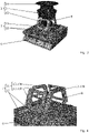
- the 1 shows a perspective view of a vehicle cooling system 1 according to the invention, which is shown in FIG 2 is shown in an exploded perspective view.
- the vehicle cooling system 1 comprises a blower device 2 for generating a cooling air flow along a main flow direction 3 and a blower housing 4 for guiding the cooling air flow generated by the blower device 2 .
- the fan housing 4 forms a flow chamber 5, the the flow of cooling air generated by the blower device 2 can flow through.
- the blower device 2 as in the 2 shown, is at least partially arranged within the flow space 5 .
- the fan device 2 is enlarged and partially exposed in FIG 3 shown.
- the fan device 2 comprises an impeller 9 and a drive motor 10 for driving the impeller 9.
- Inside the fan housing 4 there can be arranged an inflow nozzle 21 which is designed separately in relation to the fan housing 4 and in relation to the fan device 2, the flow cross-section of which in relation to the main flow direction 3 is in the direction of the fan device 2 decreases, in particular decreases non-linearly.
- the inflow nozzle 21 can be arranged on the blower device 2 .
- the vehicle cooling system 1 comprises a cooling air/cooling liquid heat exchanger 6 through which the cooling air flow can flow for cooling a cooling liquid which can flow through the cooling air/cooling liquid heat exchanger in the form of a cooling liquid flow fluidically separate from the cooling air flow.
- the vehicle cooling system 1 can have an expansion tank system 14 for the coolant, which has a plurality of separately designed individual expansion tanks 15 . How from the 1 As can be seen, the individual expansion tanks 15 can be fluidically connected to one another by means of coolant lines 16 and distributed in a circumferential direction 17 and arranged at a distance from one another on the outside of the fan housing 4 .
- the vehicle cooling system 1 comprises a carrier device 7 arranged on the cooling air/coolant liquid heat exchanger 6 for arranging the blower device 2 in the flow chamber 5. This is particularly good in the Figures 3 and 4 to recognize.
- the carrier device 7 forms a motor mount 11 and at least two fastening profiles 12, the at least two fastening profiles 12 being arranged on the cooling air/coolant heat exchanger 6, while the motor mount 11 is arranged on the two fastening profiles 12.
- the carrier device 7 in particular the motor carrier 11 , forms a receiving space 8 .
- the blower device 2 is arranged on the carrier device 7 in such a way that the drive motor 10 is arranged at least partially in the receiving space 8 and the impeller 9 is arranged outside of the receiving space 8 .
- the support device 7 and in particular the motor mount 11 is designed as a screw construction.
- the motor mount 11 comprises four frame parts 13 screwed together, two frame parts 13, 13a of the screw construction having a trapezoidal basic shape and two frame parts 13, 13b of the screw construction having a rectangular basic shape.
- the frame parts 13, 13a which have a trapezoidal basic shape, are spaced apart from one another and are each arranged on a fastening profile 12.
- the frame parts 13, 13b which have a rectangular basic shape, are spaced apart from one another and are each arranged on the two frame parts 13, 13a, which have a trapezoidal basic shape.
- the carrier device 7 is arranged to transmit the weight force of the blower device 2 exclusively on the cooling air/coolant liquid heat exchanger 6 in order to transmit the weight force.
- the expansion tank system 14 forms a cylindrical installation space 20 for at least partially accommodating the fan housing 4, the cylindrical installation space 20 in a cross section forms a cross-sectional area perpendicular to the main flow direction 3 in the form of a regular convex polygon, in particular in the form of a regular convex octagon.
- this cross-sectional area can be in the form of a circle.
- the cooling air/coolant liquid heat exchanger 6 has a heat exchanger cross section 18 transversely to the main flow direction 3, with the blower housing 4 and the individual expansion tanks 8 together having a construction space cross section 19 transversely to the main flow direction 3, which in a projection (the one shown in Fig figure 5 is shown) lies in the main flow direction 3 essentially within the heat exchanger cross section 38 .
Landscapes
- Engineering & Computer Science (AREA)
- Mechanical Engineering (AREA)
- General Engineering & Computer Science (AREA)
- Physics & Mathematics (AREA)
- Thermal Sciences (AREA)
- Automation & Control Theory (AREA)
- Transportation (AREA)
- Cooling, Air Intake And Gas Exhaust, And Fuel Tank Arrangements In Propulsion Units (AREA)
Abstract
Description
- Die vorliegende Erfindung betrifft eine Fahrzeugkühlanlage sowie eine Trägervorrichtung für eine Fahrzeugkühlanlage.
- Komponenten eines Schienenfahrzeuges, wie Stromrichter oder Transformatoren eines Triebzugs, können über eine Fahrzeugkühlanlage bzw. einen Kühlturm gekühlt werden. Ein solcher Kühlturm ist beispielsweise aus der
CN 205 220 664 U bekannt. - Nachteilig an bekannten Fahrzeugkühlanlagen ist, dass die Gebläsevorrichtung der Fahrzeugkühlanlage mit einem Gebläsegehäuse der Fahrzeugkühlanlage gewichtskraftübertragend verbunden. Hierdurch die Gehäusekonstruktion ausreichende Wandstärken aufweisen, um eine ausreichende mechanische Widerstandsfähigkeit bei einer Belastung durch das Eigengewicht der Gebläsevorrichtung, welches beispielweise bis zu 250 kg betragen kann, aufzuweisen. Außerdem sind zusätzliche Verstrebungen notwendig, um eine gewichtskraftübertragende Verbindung zwischen der Gebläsevorrichtung und dem Gebläsegehäuse auszubilden. Die erforderliche Wandstärke und die Verstrebungen früheren zur einer nachteiligen Erhörung des Eigengewichts der Fahrzeugkühlanlage.
- Ein weiter Nachteil durch die gewichtskraftübertragende Verbindung zwischen der Gebläsevorrichtung und dem Gebläsegehäuse ergibt sich dadurch, dass die Ausgestaltung des Gebläsegehäuses im Spannungsverhältnis zwischen erforderlicher mechanischer Widerstandsfähigkeit und gewünschter strömungstechnischer Ausgestaltung erfolgen muss. Hierdurch kann eine strömungstechnisch optimale Ausgestaltung des Gebläsegehäuses nicht bereitgestellt werden.
- Die vorliegende Erfindung beschäftigt sich mit dem Problem, eine verbesserte oder zumindest eine alternative Ausführungsform einer Fahrzeugkühlanlage und/oder einer Trägervorrichtung für eine Fahrzeugkühlanlage anzugeben, die insbesondere eine Reduktion des Gesamtgewichtes der Fahrzeugkühlanlage und/oder insbesondere eine strömungstechnisch optimale Ausgestaltung des Gebläsegehäuses ermöglicht.
- Dieses Problem wird erfindungsgemäß durch die Gegenstände der unabhängigen Ansprüche gelöst. Vorteilhafte Ausführungsformen sind Gegenstand der abhängigen Ansprüche.
- Die vorliegende Erfindung beruht auf dem allgemeinen Gedanken, eine Trägervorrichtung zur Anordnung einer Gebläsevorrichtung der Fahrzeugkühlanlage derart auszubilden, dass die Trägervorrichtung zur Übertragung der Gewichtskraft der Gebläsevorrichtung ausschließlich an einem Kühlluft-Kühlflüssigkeits-Wärmeübertrager der Fahrzeugkühlanlage gewichtskraftübertragend angeordnet ist.
- Die erfindungsgemäße Fahrzeugkühlanlage, insbesondere für ein Schienenfahrzeug, weist eine Gebläsevorrichtung zur Erzeugung eines Kühlluftstromes entlang einer Hauptströmungsrichtung auf. Ferner weist die Fahrzeugkühlanlage ein Gebläsegehäuse zur Strömungsführung des durch die Gebläsevorrichtung erzeugten Kühlluftstromes auf, wobei das Gebläsegehäuse einen Strömungsraum ausbildet, den der durch die Gebläsevorrichtung erzeugte Kühlluftstrom durchströmen kann. Die Gebläsevorrichtung kann als Ventilator, insbesondere als Axialventilator, mit einem elektrischen Antrieb ausgebildet sein.
- Die Hauptströmungsrichtung kann parallel zu einer Längsmittelachse des Gebläsegehäuses ausgerichtet sein. Die Umfangsrichtung, insbesondere die Umfangsrichtung um das Gebläsegehäuse, kann um die Hauptströmungsrichtung und/oder die Längsmittelachse des Gebläsegehäuses ausgerichtet sein. Hierbei kann die Umfangsrichtung in einer Querebene liegen, die quer und/oder senkrecht zur Hauptströmungsrichtung und/oder zur Längsmittelachse des Gebläsegehäuses ausgerichtet ist.
- Ferner weist die Fahrzeugkühlanlage einen vom Kühlluftstrom durchströmbaren Kühlluft-Kühlflüssigkeits-Wärmeübertrager zur Kühlung einer Kühlflüssigkeit auf, die den Kühlluft-Kühlflüssigkeits-Wärmeübertrager in Form eines Kühlflüssigkeitsstromes fluidisch getrennt vom Kühlluftstrom durchströmen kann.
- Ferner weist die Fahrzeugkühlanlage eine an dem Kühlluft-Kühlflüssigkeits-Wärmeübertrager angeordnete Trägervorrichtung zur Anordnung der Gebläsevorrichtung im Strömungsraum auf, wobei die Trägervorrichtung einen Aufnahmeraum ausbildet. Insbesondere kann die Trägervorrichtung den Aufnahmeraum begrenzen. Unter dem Aufnahmeraum kann der Raum, insbesondere Luftraum, verstanden werden, der innerhalb der Trägervorrichtung ausgebildet ist. Die Trägervorrichtung kann separat bezüglich des Kühlluft-Kühlflüssigkeits-Wärmeübertragers und/oder separat bezüglich des Gebläsegehäuses ausgebildet sein.
- Die Gebläsevorrichtung ist wenigstens teilweise innerhalb des Strömungsraumes angeordnet, wobei die Gebläsevorrichtung ein Laufrad und einen Antriebsmotor zum Antrieb des Laufrades aufweist. Das Laufrad kann ein Axiallaufrad sein, welches vom Kühlluftstrom axial durchströmt werden kann. Der Antriebsmotor kann ein Elektromotor sein. Der Antriebsmotor kann wenigstens teilweise bezüglich der Hauptströmungsrichtung versetzt zum Laufrad angeordnet sein, sodass der Antriebsmotor bezüglich der Hauptströmungsrichtung näher am Kühlluft-Kühlflüssigkeits-Wärmeübertrager angeordnet ist als das Laufrad.
- Die Gebläsevorrichtung ist so an der Trägervorrichtung angeordnet, dass der Antriebsmotor wenigstens teilweise im Aufnahmeraum und das Laufrad außerhalb des Aufnahmeraumes angeordnet ist. Die Gebläsevorrichtung kann berührungsfrei bezüglich des Kühlluft-Kühlflüssigkeits-Wärmeübertragers und/oder berührungsfrei bezüglich des Gebläsegehäuses angeordnet sein.
- Die Trägervorrichtung ist zur Übertragung der Gewichtskraft der Gebläsevorrichtung ausschließlich am Kühlluft-Kühlflüssigkeits-Wärmeübertrager gewichtskraftübertragend angeordnet. Die Trägervorrichtung kann berührungsfrei bezüglich des Gebläsegehäuses angeordnet sein.
- Da eine Übertragung der Gewichtskraft der Gebläsevorrichtung auf das Gebläsegehäuse verhindert wird, kann eine Reduktion des Gesamtgewichtes der Fahrzeugkühlanlage erzielt werden, in dem kleine Wandstärken einsetzbar sind ohne die erforderliche mechanische Widerstandfähigkeit des Gebläsegehäuses zu reduzieren. Zusätzlich kann durch die kleine Wandstärken eine Materialreduktion und somit eine Kostenreduktion erzielt werden. Ferner kann das Gebläsegehäuse unabhängig von einer einwirkenden Gewichtskraft der Gebläsevorrichtung strömungstechnisch optimiert ausgebildet werden. Somit dient das Gebläsegehäuse ausschließlich der Kühlluftführung.
- Bei einer vorteilhaften Weiterbildung der erfindungsgemäßen Lösung ist vorgesehen, dass die Trägervorrichtung einen Motorträger und wenigstens zwei Befestigungsprofile ausbildet, wobei die wenigstens zwei Befestigungsprofile am Kühlluft-Kühlflüssigkeits-Wärmeübertrager angeordnet sind und dass der Motorträger an den zwei Befestigungsprofilen angeordnet ist. Die Befestigungsprofile können jeweils zueinander separat und jeweils separat bezüglich des Motorträgers ausgebildet sein.
- Die Befestigungsprofile können voneinander beabstandet angeordnet sein. Die Befestigungsprofile können bezüglich ihrer Längsachse parallel zueinander ausgerichtet sein. Die Befestigungsprofile können eine Längserstreckung bezüglich ihrer Längsachse aufweisen, die größer ist als eine Höhe des Aufnahmeraumes bezüglich der Hauptströmungsrichtung.
- Über die Befestigungsprofile kann eine verbesserte Verteilung der auf den Kühlluft-Kühlflüssigkeits-Wärmeübertrager übertragenen Gewichtskraft der Gebläsevorrichtung erzielt werden.
- Bei einer weiteren vorteilhaften Ausführungsform der erfindungsgemäßen Lösung ist vorgesehen, dass der Motorträger berührungsfrei, insbesondere vollständig berührungsfrei und/oder vollständig beabstandet, bezüglich des Gebläsegehäuses angeordnet ist.
- Hierdurch kann eine Übertragung der Gewichtskraft der Gebläsevorrichtung auf das Gebläsegehäuse verhindert werden.
- Bei einer vorteilhaften Weiterbildung der erfindungsgemäßen Lösung ist vorgesehen, dass der Motorträger den Aufnahmeraum der Trägervorrichtung ausbildet, und/oder dass der Aufnahmeraum der Trägervorrichtung in Form eines Pyramidenstumpfes ausgebildet ist.
- Der Motorträger kann einen Aufnahmeraum in Form eines Pyramidenstumpfes ausbilden und/oder begrenzen, wobei die Grundfläche des Pyramidenstumpfes an den Befestigungsprofilen ausgebildet sein kann und die im Vergleich zur Grundfläche kleinere Deckfläche beabstandet von den Befestigungsprofilen ausgebildet ist. Hierdurch kann auch der Motorträger pyramidenstumpfartig ausgebildet sein. Hierdurch kann eine verbesserte Verteilung der auf die Befestigungsprofile übertragenen Gewichtskraft der Gebläsevorrichtung erzielt werden.
- Bei einer weiteren vorteilhaften Ausführungsform der erfindungsgemäßen Lösung ist vorgesehen, dass der Motorträger als Schraubkonstruktion mehrerer separater Rahmenteile ausgebildet ist, und/oder dass der Motorträger mit den zwei Befestigungsprofilen verschraubt ist, und/oder dass die zwei Befestigungsprofile mit dem Kühlluft-Kühlflüssigkeits-Wärmeübertrager verschraubt sind, und/oder dass die Befestigungsprofile jeweils als Hohlprofile, insbesondere als Rechteckhohlprofile, ausgebildet sind.
- Ein Rahmenteil kann ein Rahmen mit einer Durchbruchsöffnung sein. Die Durchbruchsöffnung kann vom Material des Rahmens umlaufend, insbesondere durchgehend umlaufend, umschlossen und/oder begrenzt sein.
- Die Schraubkonstruktion kann mehrere separat ausgebildete Rahmenteile umfassen, die miteinander verschraubt sein können. Hierdurch wird eine modulare Bauweise des Motorträgers bereitgestellt. Da die Rahmenteile separat bei der Fertigung, Lackierarbeiten und der Endmontage gehandhabt werden können, muss lediglich ein Bruchteil des Gesamtgewichtes des Motorträgers beim jeweiligen Arbeitsschritt gehandhabt werden. Die Rahmenteile lassen sich einfach und kostengünstig herstellen. Der Motorträger lässt einfach und kostengünstig verschiedene Baugrößen anpassen.
- Der Einsatz von Hohlprofilen ermöglicht eine weitere Gewichtsreduktion-
- Eine Verschraubung der Rahmenteile und/oder des Motorträger mit den Befestigungsprofilen und/oder der Befestigungsprofile mit dem Kühlluft-Kühlflüssigkeits-Wärmeübertrager kann mittels Schraubmittels ausgebildet sein. Insgesamt kann hierdurch auf eine komplexe und arbeitsaufwendige Schweißkonstruktion verzichtet werden.
- Bei einer vorteilhaften Weiterbildung der erfindungsgemäßen Lösung ist vorgesehen, dass der als Schraubkonstruktion ausgebildete Motorträger vier miteinander verschraubte Rahmenteile aufweist. Hierbei weisen zwei Rahmenteile der Schraubkonstruktion eine trapezartige Grundform auf, wohingegen zwei weitere Rahmenteile der Schraubkonstruktion eine rechteckartige Grundform aufweisen. Die Rahmenteile, die eine trapezartige Grundform aufweisen, sind voneinander beabstandet und jeweils an einem Befestigungsprofil angeordnet. Die Rahmenteile, die eine rechteckartige Grundform aufweisen, sind voneinander beabstandet und jeweils an den beiden Rahmenteilen, die eine trapezartige Grundform aufweisen, angeordnet. Die Rahmenteile können separat voneinander ausgebildet und/oder hergestellt sein.
- Die Rahmenteile können jeweils eine Durchbruchsöffnung aufweisen, die eine zur Grundform des Rahmenteils formähnliche Durchbruchsöffnungskontur aufweisen. Mit anderen Worten ausgedrückt, kann ein Rahmenteil mit trapezartiger Grundform eine Durchbruchsöffnung mit einer trapezartigen Durchbruchsöffnungskontur aufweisen, wohingegen ein Rahmenteil mit rechteckartiger Grundform eine Durchbruchsöffnung mit einer rechteckartigen Durchbruchsöffnungskontur aufweisen kann. Diese Durchbruchsöffnungskontur können abgerundete Eckbereiche ausbilden, um unzulässige mechanische Spannungen im Rahmenteil zu vermeiden.
- Bei einer weiteren vorteilhaften Ausführungsform der erfindungsgemäßen Lösung ist vorgesehen, dass ein Ausgleichbehältersystem für die Kühlflüssigkeit ausgebildet ist, welches mehrere separat ausgebildete Einzelausgleichsbehälter aufweist, die mittels Kühlflüssigkeitsleitungen fluidisch miteinander verbunden sind und die in einer Umfangsrichtung verteilt und voneinander beabstandet außen am Gebläsegehäuse angeordnet sind. Die voneinander beabstandet angeordnete Einzelausgleichsbehälter können im Wesentlichen gleichartig, insbesondere gleichartig, ausgebildet sein. Die Kühlflüssigkeitsleitungen können bezüglich der Einzelausgleichsbehälter separat ausgebildet sein. Unter "außen am Gebläsegehäuse" kann zu verstehen sein, dass die Einzelausgleichsbehälter außerhalb des Strömungsraumes angeordnet sind, wobei der Strömungsraum durch das Gebläsegehäuse begrenzt und/oder abgegrenzt ist.
- Der Kühlluft-Kühlflüssigkeits-Wärmeübertrager kann fluidisch mit einem geschlossen Kühlflüssigkeits-Kreislauf verbunden sein. Das Ausgleichbehältersystem, insbesondere wenigstens Einzelausgleichsbehälter, kann fluidisch mit diesem Kühlflüssigkeits-Kreislauf verbunden sein.
- Die Einzelausgleichsbehälter können bezüglich der Umfangsrichtung im Wesentlichen äquidistant, insbesondere äquidistant, außen am Gebläsegehäuse angeordnet sein. Die Einzelausgleichsbehälter können jeweils bezüglich der Hauptströmungsrichtung und/oder bezüglich der Längsmittelachse des Gebläsegehäuses eine Längserstreckung aufweisen, die wenigstens 50%, insbesondere wenigstens 75% oder wenigstens 85%, der Längserstreckung des Gebläsegehäuses bezüglich der Hauptströmungsrichtung und/oder bezüglich der Längsmittelachse entspricht. Die Einzelausgleichsbehälter können jeweils bezüglich der Hauptströmungsrichtung und/oder bezüglich der Längsmittelachse des Gebläsegehäuses eine Längserstreckung aufweisen, die der Längserstreckung des Gebläsegehäuses bezüglich der Hauptströmungsrichtung und/oder bezüglich der Längsmittelachse entspricht.
- Die Einzelausgleichsbehälter können jeweils am Gebläsegehäuse lose anliegend angeordnet sein und/oder bezüglich des Gebläsegehäuses verschiebbar angeordnet sein. Hierdurch kann verhindert werden, dass die Gewichtskraft der Einzelausgleichsbehälter und die Gewichtkraft der in den Einzelausgleichsbehältern aufgenommen Kühlflüssigkeit auf das Gebläsegehäuse übertragen und/oder in das Gebläsegehäuse eingeleitet wird. Somit hat das Gewicht des Ausgleichbehältersystems, insbesondere das Gewicht der im Ausgleichbehältersystem aufgenommenen Kühlflüssigkeit, keinen Einfluss auf die mechanische Ausgestaltung des Gebläsegehäuses, die eine ausreichende mechanische Widerstandfähigkeit des Gebläsegehäuses gewährleistet.
- Das Ausgleichbehältersystem kann ein Aufnahmevolumen von wenigstens 100 L (bzw. 0,10 m3), insbesondere von 200 bis 320 L (bzw. 0,20 bis 0,32 m3), zur Aufnahme der Kühlflüssigkeit aufweisen. Dieses Aufnahmevolumen kann im Wesentlichen gleichverteilt, insbesondere gleichverteilt, bezüglich der separat ausgebildeten Einzelausgleichsbehälter des Ausgleichbehältersystems sein.
- Die Gebläsevorrichtung ist wenigstens teilweise innerhalb des Strömungsraumes angeordnet, wobei der Kühlluft-Kühlflüssigkeits-Wärmeübertrager stromab der Gebläsevorrichtung bezüglich der Hauptströmungsrichtung des Kühlluftstromes angeordnet ist.
- Bei der erfindungsgemäßen Fahrzeugkühlanlage dient das Gebläsegehäuse ausschließlich der Luftführung, sodass eine Reduktion der Materialkosten durch einen zweckmäßigen Materialeinsatz am Gebläsegehäuse ermöglicht wird. Das im Vergleich zum Ausgleichbehältersystem geringere Eigenleergewicht der Einzelausgleichsbehälter erleichtert die Handhabung bei der Fertigung, bei Lackierarbeiten und bei der Endmontage. Somit sind die Einzelbauteile des Ausgleichbehältersystems, insbesondere die Einzelbauteile der Einzelausgleichsbehälter, einfach und kostengünstig zu fertigen. Der Einsatz der Einzelausgleichsbehälter lässt sich unkompliziert an verschiedene Gesamtvolumina anpassen.
- Durch die bezüglich der Umfangsrichtung verteilen Einzelausgleichsbehälter ergibt sich für die Fahrzeugkühlanlage ein vorteilhafterer Gesamtschwerpunkt, der bezüglich der Hauptströmungsrichtung näher am Kühlluft-Kühlflüssigkeits-Wärmeübertrager liegt, sodass eine verbesserte mechanischen Stabilität bzw. Standfestigkeit erzielt wird. Zusätzlich kann durch die bezüglich der Umfangsrichtung verteilen Einzelausgleichsbehälter ein höheres Aufnahmevolumen bei verbesserten mechanischen Stabilität bzw. Standfestigkeit bereitgestellt werden.
- Bei einer vorteilhaften Weiterbildung der erfindungsgemäßen Lösung ist vorgesehen, dass der Kühlluft-Kühlflüssigkeits-Wärmeübertrager quer zur Hauptströmungsrichtung einen Wärmeübertragerquerschnitt aufweist, wobei das Gebläsegehäuse und die Einzelausgleichsbehälter quer zur Hauptströmungsrichtung gemeinsam einen Bauraumquerschnitt aufweisen, der in einer Projektion in der Hauptströmungsrichtung im Wesentlichen innerhalb des Wärmeübertragerquerschnitts liegt. Hierunter kann auch zu verstehen sein, dass der Bauraumquerschnitt in einer Projektion in der Hauptströmungsrichtung im Wesentlichen dem Wärmeübertragerquerschnitt entspricht, insbesondere bezüglich der Querschnittskontur entspricht.
- Es kann vorgesehen sein, dass der Motorträger quer zur Hauptströmungsrichtung einen Motorträgerquerschnitt aufweist. Es kann vorgesehen sein, dass das Gebläsegehäuse quer zur Hauptströmungsrichtung einen Gebläsegehäusequerschnitt aufweist. Der Motorträgerquerschnitt kann in einer Projektion in der Hauptströmungsrichtung im Wesentlichen innerhalb des Wärmeübertragerquerschnitts oder im Wesentlichen innerhalb des Gebläsegehäusequerschnitts liegen.
- Der Bauraumquerschnitt kann durch eine fiktive Querschnittsbegrenzungskontur definiert sein, die das Gebläsegehäuse und die Einzelausgleichsbehälter in einem Querschnitt quer zur Hauptströmungsrichtung begrenzt bzw. umgrenzt, wobei die fiktive Querschnittsbegrenzungskontur eine minimale Querschnittfläche aufweist. Die fiktive Querschnittsbegrenzungskontur kann der Querschnittskontur des Wärmeübertragerquerschnitts im Wesentlichen entsprechend. Ein Flächenschwerpunkt des Bauraumquerschnittes und ein Flächenschwerpunkt des Wärmeübertragerquerschnitts können bezüglich der Hauptströmungsrichtung fluchtend angeordnet sein.
- Hierdurch lässt sich eine besonders kompakte und bauraumoptimierte Ausgestaltung der Fahrzeugkühlanlage erzielen.
- Bei einer weiteren vorteilhaften Ausführungsform der erfindungsgemäßen Lösung ist vorgesehen, dass das Gebläsegehäuse eine dem Strömungsraum abgewandte Außenoberfläche aufweist, wobei die Außenoberfläche mehrere Außenoberflächenabschnitte aufweist.
- Die Außenoberflächenabschnitte der Außenoberfläche sind so angeordnet, dass die Außenoberflächenabschnitte in einem Querschnitt senkrecht zur Hauptströmungsrichtung eine Außenbegrenzung in Form eines regelmäßigen konvexen Polygons, insbesondere in Form eines regelmäßigen konvexen Achteckes, oder in Form eines Kreises ausbilden. Das regelmäßige konvexe Polygon kann eine gerade Anzahl an Seitenkanten aufweisen. Das regelmäßige konvexe Polygon kann mehr als vier Seitenkanten aufweisen.
- Hierdurch lässt sich eine besonders kompakte und bauraumoptimierte Ausgestaltung der Fahrzeugkühlanlage im Spannungsverhältnis des erforderlichen Volumens des Strömungsraums und des erforderlichen Aufnahmevolumens des Ausgleichbehältersystems erzielen.
- Bei einer vorteilhaften Weiterbildung der erfindungsgemäßen Lösung ist vorgesehen, dass das Ausgleichbehältersystem einen zylindrischen Einbauraum zur wenigstens teilweisen Aufnahme des Gebläsegehäuses ausbildet, wobei der zylindrische Einbauraum in einem Querschnitt senkrecht zur Hauptströmungsrichtung eine Querschnittsfläche in Form regelmäßigen konvexen Polygons, insbesondere in Form eines regelmäßigen konvexen Achteckes, oder in Form eines Kreises ausbildet.
- Der zylindrische Einbauraum kann in einem Querschnitt senkrecht zur Hauptströmungsrichtung eine Ausgestaltung aufweisen, die komplementär zu einer im Querschnitt senkrecht zur Hauptströmungsrichtung betrachteten Außenbegrenzung des Gebläsegehäuses ist.
- Hierdurch lässt sich eine besonders kompakte und bauraumoptimierte Ausgestaltung der Fahrzeugkühlanlage erzielen.
- Ferner betrifft die Erfindung eine Trägervorrichtung für eine Fahrzeugkühlanlage, insbesondere für eine erfindungsgemäße Fahrzeugkühlanlage.
- Die Trägervorrichtung ist zur Anordnung einer Gebläsevorrichtung der Fahrzeugkühlanlage in einem Strömungsraum der Fahrzeugkühlanlage ausgebildet. Hierbei ist die Trägervorrichtung derart ausgebildet, dass die Gebläsevorrichtung der Fahrzeugkühlanlage so an der Trägervorrichtung anordbar ist, dass ein Antriebsmotor der Gebläsevorrichtung wenigstens teilweise im Aufnahmeraum und ein Laufrad der Gebläsevorrichtung außerhalb des Aufnahmeraumes anordbar ist. Die Trägervorrichtung ist an einem Kühlluft-Kühlflüssigkeits-Wärmeübertrager der Fahrzeugkühlanlage derart gewichtskraftübertragend anordbar, dass eine Übertragung der Gewichtskraft der Gebläsevorrichtung der Fahrzeugkühlanlage ausschließlich auf den Kühlluft-Kühlflüssigkeits-Wärmeübertrager der Fahrzeugkühlanlage ausbildbar ist.
- Da eine Übertragung der Gewichtskraft der Gebläsevorrichtung auf das Gebläsegehäuse verhindert wird, kann eine Reduktion des Gesamtgewichtes der Fahrzeugkühlanlage erzielt werden, in dem kleine Wandstärken einsetzbar sind ohne die erforderliche mechanische Widerstandfähigkeit des Gebläsegehäuses zu reduzieren. Zusätzlich kann durch die kleine Wandstärken eine Materialreduktion und somit eine Kostenreduktion erzielt werden. Ferner kann das Gebläsegehäuse unabhängig von einer einwirkenden Gewichtskraft der Gebläsevorrichtung strömungstechnisch optimiert ausgebildet werden. Somit dient das Gebläsegehäuse ausschließlich der Kühlluftführung.
- Bei einer weiteren vorteilhaften Ausführungsform der erfindungsgemäßen Lösung ist vorgesehen, dass die Trägervorrichtung einen Motorträger und wenigstens zwei Befestigungsprofile ausbildet, wobei die wenigstens zwei Befestigungsprofile am Kühlluft-Kühlflüssigkeits-Wärmeübertrager der Fahrzeugkühlanlage anordbar sind und dass der Motorträger an den zwei Befestigungsprofilen angeordnet ist. Die Befestigungsprofile können jeweils zueinander separat und jeweils separat bezüglich des Motorträgers ausgebildet sein.
- Die Befestigungsprofile können voneinander beabstandet angeordnet sein. Die Befestigungsprofile können bezüglich ihrer Längsachse parallel zueinander ausgerichtet sein. Die Befestigungsprofile können eine Längserstreckung bezüglich ihrer Längsachse aufweisen, die größer ist als eine Höhe des Aufnahmeraumes bezüglich der Hauptströmungsrichtung.
- Über die Befestigungsprofile kann eine verbesserte Verteilung der auf den Kühlluft-Kühlflüssigkeits-Wärmeübertrager übertragenen Gewichtskraft der Gebläsevorrichtung erzielt werden.
- Bei einer vorteilhaften Weiterbildung der erfindungsgemäßen Lösung ist vorgesehen, dass der Motorträger berührungsfrei, insbesondere vollständig berührungsfrei und/oder vollständig beabstandet, bezüglich des Gebläsegehäuses innerhalb der Fahrzeugkühlanlage anordbar ist.
- Hierdurch kann eine Übertragung der Gewichtskraft der Gebläsevorrichtung auf das Gebläsegehäuse verhindert werden.
- Bei einer weiteren vorteilhaften Ausführungsform der erfindungsgemäßen Lösung ist vorgesehen, dass der Motorträger den Aufnahmeraum der Trägervorrichtung ausbildet, und/oder dass der Aufnahmeraum der Trägervorrichtung in Form eines Pyramidenstumpfes ausgebildet ist.
- Der Motorträger kann einen Aufnahmeraum in Form eines Pyramidenstumpfes ausbilden und/oder begrenzen, wobei die Grundfläche des Pyramidenstumpfes an den Befestigungsprofilen ausgebildet sein kann und die im Vergleich zur Grundfläche kleinere Deckfläche beabstandet von den Befestigungsprofilen ausgebildet ist. Hierdurch kann auch der Motorträger pyramidenstumpfartig ausgebildet sein. Hierdurch kann eine verbesserte Verteilung der auf die Befestigungsprofile übertragenen Gewichtskraft der Gebläsevorrichtung erzielt werden.
- Bei einer vorteilhaften Weiterbildung der erfindungsgemäßen Lösung ist vorgesehen, dass der Motorträger als Schraubkonstruktion mehrerer separater Rahmenteile ausgebildet ist, und/oder dass der Motorträger mit den zwei Befestigungsprofilen verschraubt ist, und/oder dass die zwei Befestigungsprofile mit Wärmeübertrager der Fahrzeugkühlanlage verschraubar sind, und/oder dass die Befestigungsprofile jeweils als Hohlprofile, insbesondere als Rechteckhohlprofile, ausgebildet sind.
- Ein Rahmenteil kann ein Rahmen mit einer Durchbruchsöffnung sein. Die Durchbruchsöffnung kann vom Material des Rahmens umlaufend, insbesondere durchgehend umlaufend, umschlossen und/oder begrenzt sein.
- Die Schraubkonstruktion kann mehrere separat ausgebildete Rahmenteile umfassen, die miteinander verschraubt sein können. Hierdurch wird eine modulare Bauweise des Motorträgers bereitgestellt. Da die Rahmenteile separat bei der Fertigung, Lackierarbeiten und der Endmontage gehandhabt werden können, muss lediglich ein Bruchteil des Gesamtgewichtes des Motorträgers beim jeweiligen Arbeitsschritt gehandhabt werden. Die Rahmenteile lassen sich einfach und kostengünstig herstellen. Der Motorträger lässt einfach und kostengünstig verschiedene Baugrößen anpassen.
- Der Einsatz von Hohlprofilen ermöglicht eine weitere Gewichtsreduktion-
- Eine Verschraubung der Rahmenteile und/oder des Motorträger mit den Befestigungsprofilen und/oder der Befestigungsprofile mit dem Kühlluft-Kühlflüssigkeits-Wärmeübertrager kann mittels Schraubmittels ausgebildet sein. Insgesamt kann hierdurch auf eine komplexe und arbeitsaufwendige Schweißkonstruktion verzichtet werden.
- Bei einer weiteren vorteilhaften Ausführungsform der erfindungsgemäßen Lösung ist vorgesehen, dass der als Schraubkonstruktion ausgebildete Motorträger vier miteinander verschraubte Rahmenteile aufweist. Hierbei weisen zwei Rahmenteile der Schraubkonstruktion eine trapezartige Grundform auf, wohingegen zwei weitere Rahmenteile der Schraubkonstruktion eine rechteckartige Grundform aufweisen. Die Rahmenteile, die eine trapezartige Grundform aufweisen, sind voneinander beabstandet und jeweils an einem Befestigungsprofil angeordnet. Die Rahmenteile, die eine rechteckartige Grundform aufweisen, sind voneinander beabstandet und jeweils an den beiden Rahmenteilen, die eine trapezartige Grundform aufweisen, angeordnet. Die Rahmenteile können separat voneinander ausgebildet und/oder hergestellt sein.
- Die Rahmenteile können jeweils eine Durchbruchsöffnung aufweisen, die eine zur Grundform des Rahmenteils formähnliche Durchbruchsöffnungskontur aufweisen. Mit anderen Worten ausgedrückt, kann ein Rahmenteil mit trapezartiger Grundform eine Durchbruchsöffnung mit einer trapezartigen Durchbruchsöffnungskontur aufweisen, wohingegen ein Rahmenteil mit rechteckartiger Grundform eine Durchbruchsöffnung mit einer rechteckartigen Durchbruchsöffnungskontur aufweisen kann. Diese Durchbruchsöffnungskontur können abgerundete Eckbereiche ausbilden, um unzulässige mechanische Spannungen im Rahmenteil zu vermeiden.
- Weitere wichtige Merkmale und Vorteile der Erfindung ergeben sich aus den Unteransprüchen, aus den Zeichnungen und aus der zugehörigen Figurenbeschreibung anhand der Zeichnungen.
- Es versteht sich, dass die vorstehend genannten und die nachstehend noch zu erläuternden Merkmale nicht nur in der jeweils angegebenen Kombination, sondern auch in anderen Kombinationen oder in Alleinstellung verwendbar sind, ohne den Rahmen der vorliegenden Erfindung zu verlassen.
- Bevorzugte Ausführungsbeispiele der Erfindung sind in den Zeichnungen dargestellt und werden in der nachfolgenden Beschreibung näher erläutert, wobei sich gleiche Bezugszeichen auf gleiche oder ähnliche oder funktional gleiche Komponenten beziehen.
- Es zeigen, jeweils schematisch
- Fig. 1
- eine perspektivische Ansicht einer erfindungsgemäßen Fahrzeugkühlanlage,
- Fig. 2
- eine perspektivische Explosions-Ansicht der Fahrzeugkühlanlage der
Fig. 1 , - Fig. 3
- eine perspektivische Teilansicht einer erfindungsgemäßen Fahrzeugkühlanlage,
- Fig. 4
- eine weitere perspektivische Teilansicht einer erfindungsgemäßen Fahrzeugkühlanlage, wobei eine Trägervorrichtung in einer perspektivische Explosions-Ansicht gezeigt ist,
- Fig. 5
- einen schematischen Querschnitt durch eine erfindungsgemäße Fahrzeugkühlanlage.
- Die
Fig. 1 zeigt eine perspektivische Ansicht einer erfindungsgemäßen Fahrzeugkühlanlage 1, die in derFig. 2 in einer perspektivischen Explosions-Ansicht dargestellt ist. - Die Fahrzeugkühlanlage 1 umfasst eine Gebläsevorrichtung 2 zur Erzeugung eines Kühlluftstromes entlang einer Hauptströmungsrichtung 3 und ein Gebläsegehäuse 4 zur Strömungsführung des durch die Gebläsevorrichtung 2 erzeugten Kühlluftstromes. Das Gebläsegehäuse 4 bildet einen Strömungsraum 5 aus, den der durch die Gebläsevorrichtung 2 erzeugte Kühlluftstrom durchströmen kann. Herbei ist die Gebläsevorrichtung 2, wie in der
Fig. 2 dargestellt, wenigstens teilweise innerhalb des Strömungsraumes 5 angeordnet ist. - Die Gebläsevorrichtung 2 ist vergrößert und teilweise freigelegt in der
Fig. 3 gezeigt. Die Gebläsevorrichtung 2 umfasst ein Laufrad 9 und einen Antriebsmotor 10 zum Antrieb des Laufrades 9. Innerhalb des Gebläsegehäuses 4 kann eine bezüglich des Gebläsegehäuses 4 und eine bezüglich der Gebläsevorrichtung 2 separat ausgebildete Einströmdüse 21 angeordnet sein, deren strömungsquerschnitt bezüglich der Hauptströmungsrichtung 3 in Richtung der Gebläsevorrichtung 2 abnimmt, insbesondere nichtlinear abnimmt. Die Einströmdüse 21 kann an der Gebläsevorrichtung 2 angeordnet sein. - Die Fahrzeugkühlanlage 1 umfasst einen vom Kühlluftstrom durchströmbaren Kühlluft-Kühlflüssigkeits-Wärmeübertrager 6 zur Kühlung einer Kühlflüssigkeit, die den Kühlluft-Kühlflüssigkeits-Wärmeübertrager in Form eines Kühlflüssigkeitsstromes fluidisch getrennt vom Kühlluftstrom durchströmen kann.
- Die Fahrzeugkühlanlage 1 kann ein Ausgleichbehältersystem 14 für die Kühlflüssigkeit aufweisen, welches mehrere separat ausgebildete Einzelausgleichsbehälter 15 aufweist. Wie aus der
Fig. 1 hervorgeht, können die Einzelausgleichsbehälter 15 mittels Kühlflüssigkeitsleitungen 16 fluidisch miteinander verbunden und in einer Umfangsrichtung 17 verteilt und voneinander beabstandet außen am Gebläsegehäuse 4 angeordnet sein. - Die Fahrzeugkühlanlage 1 umfasst eine einer an dem Kühlluft-Kühlflüssigkeits-Wärmeübertrager 6 angeordneten Trägervorrichtung 7 zur Anordnung der Gebläsevorrichtung 2 im Strömungsraum 5. Dies ist besonders gut in den
Fig. 3 und 4 zu erkennen. - Die Trägervorrichtung 7 bildet einen Motorträger 11 und wenigstens zwei Befestigungsprofile 12 aus, wobei die wenigstens zwei Befestigungsprofile 12 am Kühlluft-Kühlflüssigkeits-Wärmeübertrager 6 angeordnet sind, während der Motorträger 11 an den zwei Befestigungsprofilen 12 angeordnet ist.
- Die Trägervorrichtung 7, insbesondere der Motorträger 11, bildet einen Aufnahmeraum 8 aus. Die Gebläsevorrichtung 2 ist so an der Trägervorrichtung 7 angeordnet, dass der Antriebsmotor 10 wenigstens teilweise im Aufnahmeraum 8 und das Laufrad 9 außerhalb des Aufnahmeraumes 8 angeordnet ist.
- Wie in der
Fig. 3 und 4 deutlich dargestellt ist, ist die Trägervorrichtung 7 und insbesondere der Motorträger 11 als Schraubkonstruktion ausgebildet. Der Motorträger 11 umfasst vier miteinander verschraubte Rahmenteile 13, wobei zwei Rahmenteile 13, 13a der Schraubkonstruktion eine trapezartige Grundform aufweisen und wobei zwei Rahmenteile 13, 13b der Schraubkonstruktion eine rechteckartige Grundform aufweisen. Die Rahmenteile 13, 13a, die eine trapezartige Grundform aufweisen, sind voneinander beabstandet und jeweils an einem Befestigungsprofil 12 angeordnet. Die Rahmenteile 13, 13b, die eine rechteckartige Grundform aufweisen, sind voneinander beabstandet und jeweils an den beiden Rahmenteilen 13, 13a, die eine trapezartige Grundform aufweisen, angeordnet. - Die Trägervorrichtung 7 ist zur Übertragung der Gewichtskraft der Gebläsevorrichtung 2 ausschließlich am Kühlluft-Kühlflüssigkeits-Wärmeübertrager 6 gewichtskraftübertragend angeordnet.
- In der
Fig. 2 ist angedeutet, dass das Ausgleichbehältersystem 14 einen zylindrischen Einbauraum 20 zur wenigstens teilweisen Aufnahme des Gebläsegehäuses 4 ausbildet, wobei der zylindrische Einbauraum 20 in einem Querschnitt senkrecht zur Hauptströmungsrichtung 3 eine Querschnittsfläche in Form regelmäßigen konvexen Polygons, insbesondere in Form eines regelmäßigen konvexen Achteckes, ausbildet. In einer nicht dargestellten Ausführungsform kann diese Querschnittsfläche in Form eines Kreises ausbildet sein. - Wie in der
Fig. 5 schematisch angedeutet, weist der Kühlluft-Kühlflüssigkeits-Wärmeübertrager 6 quer zur Hauptströmungsrichtung 3 einen Wärmeübertragerquerschnitt 18 auf, wobei das Gebläsegehäuse 4 und die Einzelausgleichsbehälter 8 quer zur Hauptströmungsrichtung 3 gemeinsam einen Bauraumquerschnitt 19 aufweisen, der in einer Projektion (die in derFig. 5 dargestellt ist) in der Hauptströmungsrichtung 3 im Wesentlichen innerhalb des Wärmeübertragerquerschnitts 38 liegt.
Claims (16)
- Fahrzeugkühlanlage (1), insbesondere für ein Schienenfahrzeug,- mit einer Gebläsevorrichtung (2) zur Erzeugung eines Kühlluftstromes entlang einer Hauptströmungsrichtung (3),- mit einem Gebläsegehäuse (4) zur Strömungsführung des durch die Gebläsevorrichtung (2) erzeugten Kühlluftstromes,- mit einem vom Gebläsegehäuse (4) ausgebildeten Strömungsraum (5), den der durch die Gebläsevorrichtung (2) erzeugte Kühlluftstrom durchströmen kann,- mit einem vom Kühlluftstrom durchströmbaren Kühlluft-Kühlflüssigkeits-Wärmeübertrager (6) zur Kühlung einer Kühlflüssigkeit, die den Kühlluft-Kühlflüssigkeits-Wärmeübertrager in Form eines Kühlflüssigkeitsstromes fluidisch getrennt vom Kühlluftstrom durchströmen kann,- mit einer an dem Kühlluft-Kühlflüssigkeits-Wärmeübertrager (6) angeordneten Trägervorrichtung (7) zur Anordnung der Gebläsevorrichtung (2) im Strömungsraum (5),- wobei die Trägervorrichtung (7) einen Aufnahmeraum (8) ausbildet,- wobei die Gebläsevorrichtung (2) wenigstens teilweise innerhalb des Strömungsraumes (5) angeordnet ist,- wobei die Gebläsevorrichtung (2) ein Laufrad (9) und einen Antriebsmotor (10) zum Antrieb des Laufrades (9) aufweist,- wobei die Gebläsevorrichtung (2) so an der Trägervorrichtung (7) angeordnet ist, dass der Antriebsmotor (10) wenigstens teilweise im Aufnahmeraum (8) und das Laufrad (9) außerhalb des Aufnahmeraumes (8) angeordnet ist,- wobei die Trägervorrichtung (7) zur Übertragung der Gewichtskraft der Gebläsevorrichtung (2) ausschließlich am Kühlluft-Kühlflüssigkeits-Wärmeübertrager (6) gewichtskraftübertragend angeordnet ist.
- Fahrzeugkühlanlage (1) nach Anspruch 1,
dadurch gekennzeichnet,- dass die Trägervorrichtung (7) einen Motorträger (11) und wenigstens zwei Befestigungsprofile (12) ausbildet,- dass die wenigstens zwei Befestigungsprofile (12) am Kühlluft-Kühlflüssigkeits-Wärmeübertrager (6) angeordnet sind,- dass der Motorträger (11) an den zwei Befestigungsprofilen (12) angeordnet ist. - Fahrzeugkühlanlage (1) nach Anspruch 2,
dadurch gekennzeichnet,
dass der Motorträger (11) berührungsfrei, insbesondere vollständig berührungsfrei und/oder vollständig beabstandet, bezüglich des Gebläsegehäuses (4) angeordnet ist. - Fahrzeugkühlanlage (1) nach Anspruch 2 oder 3,
dadurch gekennzeichnet,- dass der Motorträger (11) den Aufnahmeraum (8) der Trägervorrichtung (7) ausbildet, und/oder- dass der Aufnahmeraum (8) der Trägervorrichtung (7) in Form eines Pyramidenstumpfes ausgebildet ist. - Fahrzeugkühlanlage (1) nach einem der Ansprüche 2 bis 4,
dadurch gekennzeichnet,- dass der Motorträger (11) als Schraubkonstruktion mehrerer separater Rahmenteile (13) ausgebildet ist, und/oder- dass der Motorträger (11) mit den zwei Befestigungsprofilen (12) verschraubt ist, und/oder- dass die zwei Befestigungsprofile (12) mit dem Kühlluft-Kühlflüssigkeits-Wärmeübertrager (6) verschraubt sind, und/oder- dass die Befestigungsprofile (12) jeweils als Hohlprofile, insbesondere als Rechteckhohlprofile, ausgebildet sind. - Fahrzeugkühlanlage (1) nach Anspruch 5,
dadurch gekennzeichnet,- dass der als Schraubkonstruktion ausgebildete Motorträger (11) vier miteinander verschraubte Rahmenteile (13) aufweist,- wobei zwei Rahmenteile (13, 13a) der Schraubkonstruktion eine trapezartige Grundform aufweisen,- wobei zwei Rahmenteile (13, 13b) der Schraubkonstruktion eine rechteckartige Grundform aufweisen,- wobei die Rahmenteile (13, 13a), die eine trapezartige Grundform aufweisen, voneinander beabstandet und jeweils an einem Befestigungsprofil (12) angeordnet sind,- wobei die Rahmenteile (13, 13b), die eine rechteckartige Grundform aufweisen, voneinander beabstandet und jeweils an den beiden Rahmenteilen (13, 13a), die eine trapezartige Grundform aufweisen, angeordnet sind. - Fahrzeugkühlanlage (1) nach einem der Ansprüche 1 bis 6,
dadurch gekennzeichnet,- dass ein Ausgleichbehältersystem (14) für die Kühlflüssigkeit ausgebildet ist, welches mehrere separat ausgebildete Einzelausgleichsbehälter (15) aufweist, die mittels Kühlflüssigkeitsleitungen (16) fluidisch miteinander verbunden sind und die in einer Umfangsrichtung (17) verteilt und voneinander beabstandet außen am Gebläsegehäuse (4) angeordnet sind,- wobei die Gebläsevorrichtung (2) wenigstens teilweise innerhalb des Strömungsraumes (5) angeordnet ist,- wobei der Kühlluft-Kühlflüssigkeits-Wärmeübertrager (6) stromab der Gebläsevorrichtung (2) bezüglich der Hauptströmungsrichtung (3) des Kühlluftstromes angeordnet ist. - Fahrzeugkühlanlage (1) nach Anspruch 7,
dadurch gekennzeichnet,- dass der Kühlluft-Kühlflüssigkeits-Wärmeübertrager (6) quer zur Hauptströmungsrichtung (3) einen Wärmeübertragerquerschnitt (18) aufweist,- dass das Gebläsegehäuse (4) und die Einzelausgleichsbehälter (8) quer zur Hauptströmungsrichtung (3) gemeinsam einen Bauraumquerschnitt (19) aufweisen, der in einer Projektion in der Hauptströmungsrichtung (3) im Wesentlichen innerhalb des Wärmeübertragerquerschnitts liegt. - Fahrzeugkühlanlage (1) nach Anspruch 7 oder 8,
dadurch gekennzeichnet,- dass das Gebläsegehäuse (4) eine dem Strömungsraum (5) abgewandte Au-ßenoberfläche aufweist,- dass die Außenoberfläche mehrere Außenoberflächenabschnitte aufweist,- dass die Außenoberflächenabschnitte der Außenoberfläche so angeordnet sind, dass die Außenoberflächenabschnitte in einem Querschnitt senkrecht zur Hauptströmungsrichtung (3) eine Außenbegrenzung in Form eines regelmäßigen konvexen Polygons, insbesondere in Form eines regelmäßigen konvexen Achteckes, oder in Form eines Kreises ausbilden. - Fahrzeugkühlanlage (1) nach einem der Ansprüche 7 bis 9,
dadurch gekennzeichnet,- dass das Ausgleichbehältersystem (7) einen zylindrischen Einbauraum (20) zur wenigstens teilweisen Aufnahme des Gebläsegehäuses (4) ausbildet,- wobei der zylindrische Einbauraum (20) in einem Querschnitt senkrecht zur Hauptströmungsrichtung (3) eine Querschnittsfläche in Form regelmäßigen konvexen Polygons, insbesondere in Form eines regelmäßigen konvexen Achteckes, oder in Form eines Kreises ausbildet. - Trägervorrichtung (7) für eine Fahrzeugkühlanlage (1), insbesondere für eine Fahrzeugkühlanlage (1) nach einem der vorangehenden Ansprüche,- wobei die Trägervorrichtung (7) zur Anordnung einer Gebläsevorrichtung (2) der Fahrzeugkühlanlage (1) in einem Strömungsraum (5) der Fahrzeugkühlanlage (1) ausgebildet ist,- wobei die Trägervorrichtung (7) derart ausgebildet ist, dass die Gebläsevorrichtung (2) der Fahrzeugkühlanlage (1) so an der Trägervorrichtung (7) anordbar ist, dass ein Antriebsmotor (10) der Gebläsevorrichtung (2) wenigstens teilweise im Aufnahmeraum (8) und ein Laufrad (9) der Gebläsevorrichtung (2) außerhalb des Aufnahmeraumes (8) anordbar ist,- wobei die Trägervorrichtung (7) an einem Kühlluft-Kühlflüssigkeits-Wärmeübertrager (6) der Fahrzeugkühlanlage (1) derart gewichtskraftübertragend anordbar ist, dass eine Übertragung der Gewichtskraft der Gebläsevorrichtung (2) der Fahrzeugkühlanlage (1) ausschließlich auf den Kühlluft-Kühlflüssigkeits-Wärmeübertrager (6) der Fahrzeugkühlanlage (1) ausbildbar ist.
- Trägervorrichtung (7) nach Anspruch 11,
dadurch gekennzeichnet,- dass die Trägervorrichtung (7) einen Motorträger (11) und wenigstens zwei Befestigungsprofile (12) ausbildet,- dass die wenigstens zwei Befestigungsprofile (12) am Kühlluft-Kühlflüssigkeits-Wärmeübertrager (6) der Fahrzeugkühlanlage (1) anordbar sind,- dass der Motorträger (11) an den zwei Befestigungsprofilen (12) angeordnet ist. - Trägervorrichtung (7) nach Anspruch 12,
dadurch gekennzeichnet,
dass der Motorträger (11) berührungsfrei, insbesondere vollständig berührungsfrei und/oder vollständig beabstandet, bezüglich des Gebläsegehäuses (4) innerhalb der Fahrzeugkühlanlage (1) anordbar ist. - Trägervorrichtung (7) nach Anspruch 12 oder 13,
dadurch gekennzeichnet,- dass der Motorträger (11) den Aufnahmeraum (8) der Trägervorrichtung (7) ausbildet, und- dass der Aufnahmeraum (8) der Trägervorrichtung (7) in Form eines Pyramidenstumpfes ausgebildet ist. - Trägervorrichtung (7) nach einem der Ansprüche 12 bis 14,
dadurch gekennzeichnet,- dass der Motorträger (11) als Schraubkonstruktion mehrerer separater Rahmenteile (13) ausgebildet ist, und/oder- dass der Motorträger (11) mit den zwei Befestigungsprofilen (12) verschraubt ist, und/oder- dass die zwei Befestigungsprofile (12) mit dem Kühlluft-Kühlflüssigkeits-Wärmeübertrager (6) der Fahrzeugkühlanlage (1) verschraubar sind, und/oder- dass die Befestigungsprofile (12) jeweils als Hohlprofile, insbesondere als Rechteckhohlprofile, ausgebildet sind. - Trägervorrichtung (7) nach Anspruch 15,
dadurch gekennzeichnet,- dass der als Schraubkonstruktion ausgebildete Motorträger (11) vier miteinander verschraubte Rahmenteile (13) aufweist,- wobei zwei Rahmenteile (13, 13a) der Schraubkonstruktion eine trapezartige Grundform aufweisen,- wobei zwei Rahmenteile (13, 13b) der Schraubkonstruktion eine rechteckartige Grundform aufweisen,- wobei die Rahmenteile (13, 13a), die eine trapezartige Grundform aufweisen, voneinander beabstandet und jeweils an einem Befestigungsprofil (12) angeordnet sind,- wobei die Rahmenteile (13, 13b), die eine rechteckartige Grundform aufweisen, voneinander beabstandet und jeweils an den beiden Rahmenteilen (13, 13a), die eine trapezartige Grundform aufweisen, angeordnet sind.
Applications Claiming Priority (1)
| Application Number | Priority Date | Filing Date | Title |
|---|---|---|---|
| DE102020212790.5A DE102020212790A1 (de) | 2020-10-09 | 2020-10-09 | Fahrzeugkühlanlage |
Publications (2)
| Publication Number | Publication Date |
|---|---|
| EP3981662A1 true EP3981662A1 (de) | 2022-04-13 |
| EP3981662B1 EP3981662B1 (de) | 2024-05-01 |
Family
ID=78073858
Family Applications (1)
| Application Number | Title | Priority Date | Filing Date |
|---|---|---|---|
| EP21200768.6A Active EP3981662B1 (de) | 2020-10-09 | 2021-10-04 | Fahrzeugkühlanlage |
Country Status (3)
| Country | Link |
|---|---|
| EP (1) | EP3981662B1 (de) |
| DE (1) | DE102020212790A1 (de) |
| ES (1) | ES2992782T3 (de) |
Cited By (1)
| Publication number | Priority date | Publication date | Assignee | Title |
|---|---|---|---|---|
| CN116061677A (zh) * | 2023-03-06 | 2023-05-05 | 新乡职业技术学院 | 一种新能源汽车冷却装置 |
Citations (5)
| Publication number | Priority date | Publication date | Assignee | Title |
|---|---|---|---|---|
| FR2189697A2 (de) * | 1972-06-23 | 1974-01-25 | Ferodo Sa | |
| US4185688A (en) * | 1977-12-22 | 1980-01-29 | General Electric Company | Cooler fan noise suppressor |
| CN203381629U (zh) * | 2013-08-05 | 2014-01-08 | 株洲联诚集团有限责任公司 | 一种双流制电力机车牵引冷却装置 |
| WO2016042231A1 (fr) * | 2014-09-16 | 2016-03-24 | Renault S.A.S | Ensemble de refroidissement pour un organe fonctionnel a refroidir comprenant un radiateur et un support de motoventilateur |
| CN205220664U (zh) | 2015-11-05 | 2016-05-11 | 中国北车集团大连机车研究所有限公司 | 电力机车多系统共用冷却塔 |
Family Cites Families (6)
| Publication number | Priority date | Publication date | Assignee | Title |
|---|---|---|---|---|
| DE19641642A1 (de) | 1995-10-20 | 1997-04-24 | Carrier Corp | Auf dem Dach montiertes Klimagerät |
| DE19636679C2 (de) | 1996-09-10 | 1999-05-20 | Ernst Gaus | Klimagerät für Fahrzeugkabinen |
| US6763669B1 (en) | 2003-05-05 | 2004-07-20 | Carrier Corporation | Modular air conditioner for a bus rooftop |
| DE102005028890C5 (de) | 2005-06-22 | 2013-09-19 | Spheros Gmbh | Klimatisierungs-Dachmodul |
| DE102009058855B4 (de) | 2009-11-24 | 2014-09-11 | Spheros Gmbh | Axialgebläseanordnung |
| DE102015211610A1 (de) | 2015-06-23 | 2016-12-29 | Mahle International Gmbh | Klimaanlage für ein Fahrzeug, insbesondere Aufdachklimaanlage zur Montage auf einem Fahrzeugdach |
-
2020
- 2020-10-09 DE DE102020212790.5A patent/DE102020212790A1/de active Pending
-
2021
- 2021-10-04 EP EP21200768.6A patent/EP3981662B1/de active Active
- 2021-10-04 ES ES21200768T patent/ES2992782T3/es active Active
Patent Citations (5)
| Publication number | Priority date | Publication date | Assignee | Title |
|---|---|---|---|---|
| FR2189697A2 (de) * | 1972-06-23 | 1974-01-25 | Ferodo Sa | |
| US4185688A (en) * | 1977-12-22 | 1980-01-29 | General Electric Company | Cooler fan noise suppressor |
| CN203381629U (zh) * | 2013-08-05 | 2014-01-08 | 株洲联诚集团有限责任公司 | 一种双流制电力机车牵引冷却装置 |
| WO2016042231A1 (fr) * | 2014-09-16 | 2016-03-24 | Renault S.A.S | Ensemble de refroidissement pour un organe fonctionnel a refroidir comprenant un radiateur et un support de motoventilateur |
| CN205220664U (zh) | 2015-11-05 | 2016-05-11 | 中国北车集团大连机车研究所有限公司 | 电力机车多系统共用冷却塔 |
Cited By (2)
| Publication number | Priority date | Publication date | Assignee | Title |
|---|---|---|---|---|
| CN116061677A (zh) * | 2023-03-06 | 2023-05-05 | 新乡职业技术学院 | 一种新能源汽车冷却装置 |
| CN116061677B (zh) * | 2023-03-06 | 2023-06-02 | 新乡职业技术学院 | 一种新能源汽车冷却装置 |
Also Published As
| Publication number | Publication date |
|---|---|
| ES2992782T3 (en) | 2024-12-17 |
| EP3981662B1 (de) | 2024-05-01 |
| DE102020212790A1 (de) | 2022-04-14 |
Similar Documents
| Publication | Publication Date | Title |
|---|---|---|
| DE2233737C2 (de) | Wärmetauscher, insbesondere Kühler für ein Kraftfahrzeug | |
| EP2716915A1 (de) | Gehäuse für einen Axialventilator | |
| AT398813B (de) | Ventilatoreinheit | |
| EP3981662B1 (de) | Fahrzeugkühlanlage | |
| EP3395598A1 (de) | Kraftstoffbehälter | |
| WO2023011956A1 (de) | Stirnradgetriebe | |
| DE102021201804A1 (de) | Gehäuse für eine elektrische Maschine mit einem sich selbst entlüftenden Kühlmantel | |
| DE102016225923B4 (de) | Pumpenaggregat für ein Hydrauliksystem und Kanalelement für ein Pumpenaggregat | |
| WO2012080113A1 (de) | Sammelbehälter | |
| EP2201639B1 (de) | Batteriemodul | |
| EP0759806A1 (de) | Vorrichtung zum mischen zweier fluide | |
| DE202014003915U1 (de) | Resonanzturbine | |
| DE102020132382A1 (de) | Elektromechanischer Energiewandler mit Rotorwellenkühlung | |
| DE102020105388A1 (de) | Flachrohr, Befestigungsvorrichtung, sowie Fahrzeug | |
| DE69814209T2 (de) | Wärmeerzeuger mit viskoser Flüssigkeit mit Mitteln zur Verbesserung des Wärmeübergangs | |
| EP3992050B1 (de) | Fahrzeugkühlanlage | |
| DE102020124548B4 (de) | Kühleranordnung für ein Kraftfahrzeug | |
| DE102021006332A1 (de) | Lastkraftwagen mit einem Führerhaus und einem Brennstoffzellensystem | |
| DE10356945B4 (de) | Halterung eines Kühlers | |
| DE102022123882B4 (de) | Vorrichtung zum Leiten von Kühlluft an einer Motoraufnahme für einen Ventilatormotor | |
| DE10328163A1 (de) | Wärmetauscher mit einem Gehäuse | |
| EP0512137A1 (de) | Kernreaktorbrennelement mit integriertem Trümmerfänger | |
| DE102007011814A1 (de) | Einrichtung zum Konditionieren von in einen Fahrzeuginnenraum einzuleitender Luft | |
| DE102021115702A1 (de) | Verstärkungskäfig bei einer elektrischen Maschine | |
| DE102016015919B4 (de) | Pumpenaggregat für ein Hydrauliksystem und Kanalelement für ein Pumpenaggregat |
Legal Events
| Date | Code | Title | Description |
|---|---|---|---|
| PUAI | Public reference made under article 153(3) epc to a published international application that has entered the european phase |
Free format text: ORIGINAL CODE: 0009012 |
|
| STAA | Information on the status of an ep patent application or granted ep patent |
Free format text: STATUS: THE APPLICATION HAS BEEN PUBLISHED |
|
| AK | Designated contracting states |
Kind code of ref document: A1 Designated state(s): AL AT BE BG CH CY CZ DE DK EE ES FI FR GB GR HR HU IE IS IT LI LT LU LV MC MK MT NL NO PL PT RO RS SE SI SK SM TR |
|
| STAA | Information on the status of an ep patent application or granted ep patent |
Free format text: STATUS: REQUEST FOR EXAMINATION WAS MADE |
|
| 17P | Request for examination filed |
Effective date: 20221012 |
|
| RBV | Designated contracting states (corrected) |
Designated state(s): AL AT BE BG CH CY CZ DE DK EE ES FI FR GB GR HR HU IE IS IT LI LT LU LV MC MK MT NL NO PL PT RO RS SE SI SK SM TR |
|
| GRAP | Despatch of communication of intention to grant a patent |
Free format text: ORIGINAL CODE: EPIDOSNIGR1 |
|
| STAA | Information on the status of an ep patent application or granted ep patent |
Free format text: STATUS: GRANT OF PATENT IS INTENDED |
|
| RIC1 | Information provided on ipc code assigned before grant |
Ipc: B60K 11/04 20060101ALN20231030BHEP Ipc: F28F 9/00 20060101ALI20231030BHEP Ipc: F28D 1/02 20060101ALI20231030BHEP Ipc: F04D 29/60 20060101ALI20231030BHEP Ipc: F04D 19/00 20060101ALI20231030BHEP Ipc: B61C 17/04 20060101AFI20231030BHEP |
|
| INTG | Intention to grant announced |
Effective date: 20231206 |
|
| RIC1 | Information provided on ipc code assigned before grant |
Ipc: B60K 11/04 20060101ALN20231124BHEP Ipc: F28F 9/00 20060101ALI20231124BHEP Ipc: F28D 1/02 20060101ALI20231124BHEP Ipc: F04D 29/60 20060101ALI20231124BHEP Ipc: F04D 19/00 20060101ALI20231124BHEP Ipc: B61C 17/04 20060101AFI20231124BHEP |
|
| GRAS | Grant fee paid |
Free format text: ORIGINAL CODE: EPIDOSNIGR3 |
|
| GRAA | (expected) grant |
Free format text: ORIGINAL CODE: 0009210 |
|
| STAA | Information on the status of an ep patent application or granted ep patent |
Free format text: STATUS: THE PATENT HAS BEEN GRANTED |
|
| AK | Designated contracting states |
Kind code of ref document: B1 Designated state(s): AL AT BE BG CH CY CZ DE DK EE ES FI FR GB GR HR HU IE IS IT LI LT LU LV MC MK MT NL NO PL PT RO RS SE SI SK SM TR |
|
| REG | Reference to a national code |
Ref country code: GB Ref legal event code: FG4D Free format text: NOT ENGLISH |
|
| REG | Reference to a national code |
Ref country code: CH Ref legal event code: EP |
|
| REG | Reference to a national code |
Ref country code: DE Ref legal event code: R096 Ref document number: 502021003548 Country of ref document: DE |
|
| REG | Reference to a national code |
Ref country code: IE Ref legal event code: FG4D Free format text: LANGUAGE OF EP DOCUMENT: GERMAN |
|
| REG | Reference to a national code |
Ref country code: LT Ref legal event code: MG9D |
|
| REG | Reference to a national code |
Ref country code: NL Ref legal event code: MP Effective date: 20240501 |
|
| PG25 | Lapsed in a contracting state [announced via postgrant information from national office to epo] |
Ref country code: IS Free format text: LAPSE BECAUSE OF FAILURE TO SUBMIT A TRANSLATION OF THE DESCRIPTION OR TO PAY THE FEE WITHIN THE PRESCRIBED TIME-LIMIT Effective date: 20240901 |
|
| PG25 | Lapsed in a contracting state [announced via postgrant information from national office to epo] |
Ref country code: BG Free format text: LAPSE BECAUSE OF FAILURE TO SUBMIT A TRANSLATION OF THE DESCRIPTION OR TO PAY THE FEE WITHIN THE PRESCRIBED TIME-LIMIT Effective date: 20240501 |
|
| PG25 | Lapsed in a contracting state [announced via postgrant information from national office to epo] |
Ref country code: FI Free format text: LAPSE BECAUSE OF FAILURE TO SUBMIT A TRANSLATION OF THE DESCRIPTION OR TO PAY THE FEE WITHIN THE PRESCRIBED TIME-LIMIT Effective date: 20240501 Ref country code: HR Free format text: LAPSE BECAUSE OF FAILURE TO SUBMIT A TRANSLATION OF THE DESCRIPTION OR TO PAY THE FEE WITHIN THE PRESCRIBED TIME-LIMIT Effective date: 20240501 |
|
| PG25 | Lapsed in a contracting state [announced via postgrant information from national office to epo] |
Ref country code: GR Free format text: LAPSE BECAUSE OF FAILURE TO SUBMIT A TRANSLATION OF THE DESCRIPTION OR TO PAY THE FEE WITHIN THE PRESCRIBED TIME-LIMIT Effective date: 20240802 |
|
| PG25 | Lapsed in a contracting state [announced via postgrant information from national office to epo] |
Ref country code: PT Free format text: LAPSE BECAUSE OF FAILURE TO SUBMIT A TRANSLATION OF THE DESCRIPTION OR TO PAY THE FEE WITHIN THE PRESCRIBED TIME-LIMIT Effective date: 20240902 |
|
| PG25 | Lapsed in a contracting state [announced via postgrant information from national office to epo] |
Ref country code: NL Free format text: LAPSE BECAUSE OF FAILURE TO SUBMIT A TRANSLATION OF THE DESCRIPTION OR TO PAY THE FEE WITHIN THE PRESCRIBED TIME-LIMIT Effective date: 20240501 |
|
| PG25 | Lapsed in a contracting state [announced via postgrant information from national office to epo] |
Ref country code: PL Free format text: LAPSE BECAUSE OF FAILURE TO SUBMIT A TRANSLATION OF THE DESCRIPTION OR TO PAY THE FEE WITHIN THE PRESCRIBED TIME-LIMIT Effective date: 20240501 |
|
| PG25 | Lapsed in a contracting state [announced via postgrant information from national office to epo] |
Ref country code: LV Free format text: LAPSE BECAUSE OF FAILURE TO SUBMIT A TRANSLATION OF THE DESCRIPTION OR TO PAY THE FEE WITHIN THE PRESCRIBED TIME-LIMIT Effective date: 20240501 |
|
| PG25 | Lapsed in a contracting state [announced via postgrant information from national office to epo] |
Ref country code: PT Free format text: LAPSE BECAUSE OF FAILURE TO SUBMIT A TRANSLATION OF THE DESCRIPTION OR TO PAY THE FEE WITHIN THE PRESCRIBED TIME-LIMIT Effective date: 20240902 Ref country code: PL Free format text: LAPSE BECAUSE OF FAILURE TO SUBMIT A TRANSLATION OF THE DESCRIPTION OR TO PAY THE FEE WITHIN THE PRESCRIBED TIME-LIMIT Effective date: 20240501 Ref country code: NO Free format text: LAPSE BECAUSE OF FAILURE TO SUBMIT A TRANSLATION OF THE DESCRIPTION OR TO PAY THE FEE WITHIN THE PRESCRIBED TIME-LIMIT Effective date: 20240801 Ref country code: NL Free format text: LAPSE BECAUSE OF FAILURE TO SUBMIT A TRANSLATION OF THE DESCRIPTION OR TO PAY THE FEE WITHIN THE PRESCRIBED TIME-LIMIT Effective date: 20240501 Ref country code: LV Free format text: LAPSE BECAUSE OF FAILURE TO SUBMIT A TRANSLATION OF THE DESCRIPTION OR TO PAY THE FEE WITHIN THE PRESCRIBED TIME-LIMIT Effective date: 20240501 Ref country code: IS Free format text: LAPSE BECAUSE OF FAILURE TO SUBMIT A TRANSLATION OF THE DESCRIPTION OR TO PAY THE FEE WITHIN THE PRESCRIBED TIME-LIMIT Effective date: 20240901 Ref country code: HR Free format text: LAPSE BECAUSE OF FAILURE TO SUBMIT A TRANSLATION OF THE DESCRIPTION OR TO PAY THE FEE WITHIN THE PRESCRIBED TIME-LIMIT Effective date: 20240501 Ref country code: GR Free format text: LAPSE BECAUSE OF FAILURE TO SUBMIT A TRANSLATION OF THE DESCRIPTION OR TO PAY THE FEE WITHIN THE PRESCRIBED TIME-LIMIT Effective date: 20240802 Ref country code: FI Free format text: LAPSE BECAUSE OF FAILURE TO SUBMIT A TRANSLATION OF THE DESCRIPTION OR TO PAY THE FEE WITHIN THE PRESCRIBED TIME-LIMIT Effective date: 20240501 Ref country code: BG Free format text: LAPSE BECAUSE OF FAILURE TO SUBMIT A TRANSLATION OF THE DESCRIPTION OR TO PAY THE FEE WITHIN THE PRESCRIBED TIME-LIMIT Effective date: 20240501 Ref country code: RS Free format text: LAPSE BECAUSE OF FAILURE TO SUBMIT A TRANSLATION OF THE DESCRIPTION OR TO PAY THE FEE WITHIN THE PRESCRIBED TIME-LIMIT Effective date: 20240801 |
|
| REG | Reference to a national code |
Ref country code: ES Ref legal event code: FG2A Ref document number: 2992782 Country of ref document: ES Kind code of ref document: T3 Effective date: 20241217 |
|
| PG25 | Lapsed in a contracting state [announced via postgrant information from national office to epo] |
Ref country code: DK Free format text: LAPSE BECAUSE OF FAILURE TO SUBMIT A TRANSLATION OF THE DESCRIPTION OR TO PAY THE FEE WITHIN THE PRESCRIBED TIME-LIMIT Effective date: 20240501 |
|
| PG25 | Lapsed in a contracting state [announced via postgrant information from national office to epo] |
Ref country code: EE Free format text: LAPSE BECAUSE OF FAILURE TO SUBMIT A TRANSLATION OF THE DESCRIPTION OR TO PAY THE FEE WITHIN THE PRESCRIBED TIME-LIMIT Effective date: 20240501 |
|
| PG25 | Lapsed in a contracting state [announced via postgrant information from national office to epo] |
Ref country code: CZ Free format text: LAPSE BECAUSE OF FAILURE TO SUBMIT A TRANSLATION OF THE DESCRIPTION OR TO PAY THE FEE WITHIN THE PRESCRIBED TIME-LIMIT Effective date: 20240501 |
|
| PG25 | Lapsed in a contracting state [announced via postgrant information from national office to epo] |
Ref country code: RO Free format text: LAPSE BECAUSE OF FAILURE TO SUBMIT A TRANSLATION OF THE DESCRIPTION OR TO PAY THE FEE WITHIN THE PRESCRIBED TIME-LIMIT Effective date: 20240501 Ref country code: SK Free format text: LAPSE BECAUSE OF FAILURE TO SUBMIT A TRANSLATION OF THE DESCRIPTION OR TO PAY THE FEE WITHIN THE PRESCRIBED TIME-LIMIT Effective date: 20240501 |
|
| PG25 | Lapsed in a contracting state [announced via postgrant information from national office to epo] |
Ref country code: SM Free format text: LAPSE BECAUSE OF FAILURE TO SUBMIT A TRANSLATION OF THE DESCRIPTION OR TO PAY THE FEE WITHIN THE PRESCRIBED TIME-LIMIT Effective date: 20240501 |
|
| PG25 | Lapsed in a contracting state [announced via postgrant information from national office to epo] |
Ref country code: SM Free format text: LAPSE BECAUSE OF FAILURE TO SUBMIT A TRANSLATION OF THE DESCRIPTION OR TO PAY THE FEE WITHIN THE PRESCRIBED TIME-LIMIT Effective date: 20240501 Ref country code: SK Free format text: LAPSE BECAUSE OF FAILURE TO SUBMIT A TRANSLATION OF THE DESCRIPTION OR TO PAY THE FEE WITHIN THE PRESCRIBED TIME-LIMIT Effective date: 20240501 Ref country code: RO Free format text: LAPSE BECAUSE OF FAILURE TO SUBMIT A TRANSLATION OF THE DESCRIPTION OR TO PAY THE FEE WITHIN THE PRESCRIBED TIME-LIMIT Effective date: 20240501 Ref country code: EE Free format text: LAPSE BECAUSE OF FAILURE TO SUBMIT A TRANSLATION OF THE DESCRIPTION OR TO PAY THE FEE WITHIN THE PRESCRIBED TIME-LIMIT Effective date: 20240501 Ref country code: DK Free format text: LAPSE BECAUSE OF FAILURE TO SUBMIT A TRANSLATION OF THE DESCRIPTION OR TO PAY THE FEE WITHIN THE PRESCRIBED TIME-LIMIT Effective date: 20240501 Ref country code: CZ Free format text: LAPSE BECAUSE OF FAILURE TO SUBMIT A TRANSLATION OF THE DESCRIPTION OR TO PAY THE FEE WITHIN THE PRESCRIBED TIME-LIMIT Effective date: 20240501 |
|
| REG | Reference to a national code |
Ref country code: DE Ref legal event code: R097 Ref document number: 502021003548 Country of ref document: DE |
|
| PLBE | No opposition filed within time limit |
Free format text: ORIGINAL CODE: 0009261 |
|
| STAA | Information on the status of an ep patent application or granted ep patent |
Free format text: STATUS: NO OPPOSITION FILED WITHIN TIME LIMIT |
|
| 26N | No opposition filed |
Effective date: 20250204 |
|
| PG25 | Lapsed in a contracting state [announced via postgrant information from national office to epo] |
Ref country code: SI Free format text: LAPSE BECAUSE OF FAILURE TO SUBMIT A TRANSLATION OF THE DESCRIPTION OR TO PAY THE FEE WITHIN THE PRESCRIBED TIME-LIMIT Effective date: 20240501 |
|
| REG | Reference to a national code |
Ref country code: CH Ref legal event code: PL |
|
| PG25 | Lapsed in a contracting state [announced via postgrant information from national office to epo] |
Ref country code: MC Free format text: LAPSE BECAUSE OF FAILURE TO SUBMIT A TRANSLATION OF THE DESCRIPTION OR TO PAY THE FEE WITHIN THE PRESCRIBED TIME-LIMIT Effective date: 20240501 |
|
| PG25 | Lapsed in a contracting state [announced via postgrant information from national office to epo] |
Ref country code: BE Free format text: LAPSE BECAUSE OF NON-PAYMENT OF DUE FEES Effective date: 20241031 Ref country code: LU Free format text: LAPSE BECAUSE OF NON-PAYMENT OF DUE FEES Effective date: 20241004 |
|
| PG25 | Lapsed in a contracting state [announced via postgrant information from national office to epo] |
Ref country code: CH Free format text: LAPSE BECAUSE OF NON-PAYMENT OF DUE FEES Effective date: 20241031 |
|
| REG | Reference to a national code |
Ref country code: BE Ref legal event code: MM Effective date: 20241031 |
|
| PG25 | Lapsed in a contracting state [announced via postgrant information from national office to epo] |
Ref country code: SE Free format text: LAPSE BECAUSE OF FAILURE TO SUBMIT A TRANSLATION OF THE DESCRIPTION OR TO PAY THE FEE WITHIN THE PRESCRIBED TIME-LIMIT Effective date: 20240501 |
|
| PG25 | Lapsed in a contracting state [announced via postgrant information from national office to epo] |
Ref country code: IE Free format text: LAPSE BECAUSE OF NON-PAYMENT OF DUE FEES Effective date: 20241004 |
|
| P01 | Opt-out of the competence of the unified patent court (upc) registered |
Free format text: CASE NUMBER: UPC_APP_8059_3981662/2025 Effective date: 20250926 |
|
| PGFP | Annual fee paid to national office [announced via postgrant information from national office to epo] |
Ref country code: DE Payment date: 20251021 Year of fee payment: 5 |
|
| PGFP | Annual fee paid to national office [announced via postgrant information from national office to epo] |
Ref country code: AT Payment date: 20260113 Year of fee payment: 5 |
|
| PGFP | Annual fee paid to national office [announced via postgrant information from national office to epo] |
Ref country code: IT Payment date: 20251024 Year of fee payment: 5 |
|
| PGFP | Annual fee paid to national office [announced via postgrant information from national office to epo] |
Ref country code: FR Payment date: 20251030 Year of fee payment: 5 |
|
| PG25 | Lapsed in a contracting state [announced via postgrant information from national office to epo] |
Ref country code: CY Free format text: LAPSE BECAUSE OF FAILURE TO SUBMIT A TRANSLATION OF THE DESCRIPTION OR TO PAY THE FEE WITHIN THE PRESCRIBED TIME-LIMIT; INVALID AB INITIO Effective date: 20211004 |
|
| PGFP | Annual fee paid to national office [announced via postgrant information from national office to epo] |
Ref country code: ES Payment date: 20251216 Year of fee payment: 5 |
|
| PG25 | Lapsed in a contracting state [announced via postgrant information from national office to epo] |
Ref country code: HU Free format text: LAPSE BECAUSE OF FAILURE TO SUBMIT A TRANSLATION OF THE DESCRIPTION OR TO PAY THE FEE WITHIN THE PRESCRIBED TIME-LIMIT; INVALID AB INITIO Effective date: 20211004 |