EP3981567A1 - Tire molding die and pneumatic tire - Google Patents
Tire molding die and pneumatic tire Download PDFInfo
- Publication number
- EP3981567A1 EP3981567A1 EP20819343.3A EP20819343A EP3981567A1 EP 3981567 A1 EP3981567 A1 EP 3981567A1 EP 20819343 A EP20819343 A EP 20819343A EP 3981567 A1 EP3981567 A1 EP 3981567A1
- Authority
- EP
- European Patent Office
- Prior art keywords
- sipe
- blade
- tire
- molding die
- original shape
- Prior art date
- Legal status (The legal status is an assumption and is not a legal conclusion. Google has not performed a legal analysis and makes no representation as to the accuracy of the status listed.)
- Withdrawn
Links
- 238000000465 moulding Methods 0.000 title claims abstract description 162
- 239000000463 material Substances 0.000 claims description 21
- 230000003746 surface roughness Effects 0.000 claims description 12
- 238000004073 vulcanization Methods 0.000 description 23
- 238000010586 diagram Methods 0.000 description 15
- 238000005452 bending Methods 0.000 description 9
- 238000006243 chemical reaction Methods 0.000 description 8
- 238000011156 evaluation Methods 0.000 description 8
- 238000004519 manufacturing process Methods 0.000 description 7
- 210000000988 bone and bone Anatomy 0.000 description 6
- 230000007547 defect Effects 0.000 description 2
- 230000000694 effects Effects 0.000 description 2
- 239000007769 metal material Substances 0.000 description 2
- NINIDFKCEFEMDL-UHFFFAOYSA-N Sulfur Chemical compound [S] NINIDFKCEFEMDL-UHFFFAOYSA-N 0.000 description 1
- 230000015556 catabolic process Effects 0.000 description 1
- 239000000470 constituent Substances 0.000 description 1
- 230000007423 decrease Effects 0.000 description 1
- 238000006731 degradation reaction Methods 0.000 description 1
- 238000000034 method Methods 0.000 description 1
- 230000002093 peripheral effect Effects 0.000 description 1
- 238000000926 separation method Methods 0.000 description 1
- 238000004904 shortening Methods 0.000 description 1
- 229910001220 stainless steel Inorganic materials 0.000 description 1
- 239000010935 stainless steel Substances 0.000 description 1
- 229910052717 sulfur Inorganic materials 0.000 description 1
- 239000011593 sulfur Substances 0.000 description 1
Images




Classifications
-
- B—PERFORMING OPERATIONS; TRANSPORTING
- B29—WORKING OF PLASTICS; WORKING OF SUBSTANCES IN A PLASTIC STATE IN GENERAL
- B29C—SHAPING OR JOINING OF PLASTICS; SHAPING OF MATERIAL IN A PLASTIC STATE, NOT OTHERWISE PROVIDED FOR; AFTER-TREATMENT OF THE SHAPED PRODUCTS, e.g. REPAIRING
- B29C33/00—Moulds or cores; Details thereof or accessories therefor
- B29C33/42—Moulds or cores; Details thereof or accessories therefor characterised by the shape of the moulding surface, e.g. ribs or grooves
- B29C33/424—Moulding surfaces provided with means for marking or patterning
-
- B—PERFORMING OPERATIONS; TRANSPORTING
- B29—WORKING OF PLASTICS; WORKING OF SUBSTANCES IN A PLASTIC STATE IN GENERAL
- B29D—PRODUCING PARTICULAR ARTICLES FROM PLASTICS OR FROM SUBSTANCES IN A PLASTIC STATE
- B29D30/00—Producing pneumatic or solid tyres or parts thereof
- B29D30/06—Pneumatic tyres or parts thereof (e.g. produced by casting, moulding, compression moulding, injection moulding, centrifugal casting)
- B29D30/0601—Vulcanising tyres; Vulcanising presses for tyres
- B29D30/0606—Vulcanising moulds not integral with vulcanising presses
-
- B—PERFORMING OPERATIONS; TRANSPORTING
- B29—WORKING OF PLASTICS; WORKING OF SUBSTANCES IN A PLASTIC STATE IN GENERAL
- B29D—PRODUCING PARTICULAR ARTICLES FROM PLASTICS OR FROM SUBSTANCES IN A PLASTIC STATE
- B29D30/00—Producing pneumatic or solid tyres or parts thereof
- B29D30/06—Pneumatic tyres or parts thereof (e.g. produced by casting, moulding, compression moulding, injection moulding, centrifugal casting)
- B29D30/0601—Vulcanising tyres; Vulcanising presses for tyres
- B29D30/0606—Vulcanising moulds not integral with vulcanising presses
- B29D2030/0607—Constructional features of the moulds
- B29D2030/0613—Means, e.g. sipes or blade-like elements, for forming narrow recesses in the tyres, e.g. cuts or incisions for winter tyres
Definitions
- the present invention relates to a tire molding die and a pneumatic tire.
- Some known pneumatic tires are provided with so-called sipes, which are cuts formed in a tread portion, in order to improve performance on ice and snow, which is running performance on snowy roads and frozen road surfaces, and wet performance, which is running performance on wet road surfaces, and the like.
- sipes are cuts formed in a tread portion, in order to improve performance on ice and snow, which is running performance on snowy roads and frozen road surfaces, and wet performance, which is running performance on wet road surfaces, and the like.
- sipes are cuts formed in a tread portion, in order to improve performance on ice and snow, which is running performance on snowy roads and frozen road surfaces, and wet performance, which is running performance on wet road surfaces, and the like.
- a large number of sipes on the road contact surface of the tread portion are disposed.
- the pneumatic tire is manufactured by vulcanization molding using a tire molding die divided into a plurality of sectors in the tire circumferential direction.
- various defects are likely to occur during vulcanization
- a turning point is provided on sipe blades disposed adjacent to the division positions of sectors.
- a portion from the turning point to the other end of the sipe blade further away from the division position than the original shape separation of and damage to the sipe blade and the like are prevented during vulcanization release.
- a tire molding die described in Patent Document 2 by making the sipe volume of the sipe forming blade at the end portion position of the sector greater than the sipe volume of the sipe forming blade at the central portion position of the sector, uneven wear of a land portion at or near the division position of sectors is effectively suppressed.
- the blades are likely to be twisted in a case where the tire is detached from the mold after vulcanization molding of the tire.
- the twist may cause failure such as bending or breakage of the blades.
- the known tire molding dies that include a plurality of the sectors separated from one another in the tire circumferential direction and in which the sipe blades are disposed, there is room for improvement in terms of durability due to the likelihood of failure in the blades disposed at or near the division position of sectors.
- an object of the present invention is to provide a tire molding die and a pneumatic tire that can improve durability of sipe blades.
- a tire molding die includes a plurality of sectors separated from one another in a tire circumferential direction, and a plurality of sipe blades disposed on tread molding surfaces of the sectors, the sipe blades are disposed repeatedly in the tire circumferential direction in a repeating pattern corresponding to a predetermined arrangement pattern, a near sipe blade that is included in a plurality of the sipe blades disposed in one of the sectors and that is closest to a division position between the sectors being more rigid than an original shape blade corresponding to the sipe blade provided in the repeating pattern differing from the repeating pattern including the near sipe blade at a position identical to a position of the near sipe blade in the repeating pattern including the near sipe blade.
- a maximum height of the near sipe blade is smaller than a maximum height of the original shape blade.
- a ratio of a maximum height HI of the near sipe blade to a maximum height H2 of the original shape blade is in a range 0.3 ⁇ (H1/H2) ⁇ 0.8.
- the near sipe blade has a relationship between the maximum height HI and a sipe volume V corresponding to a product of a length L, a width W, and the maximum height HI of the near sipe blade such that V ⁇ HI.
- the near sipe blade and the original shape blade have a relationship between a number of bend points A1 of the near sipe blade and a number of bend points A2 of the original shape blade such that A2 ⁇ A1.
- the near sipe blade and the original shape blade have a relationship between a material strength S1 of the near sipe blade and a material strength S2 of the original shape blade such that S2 ⁇ S1.
- the near sipe blade and the original shape blade have a relationship between a surface roughness R1 of the near sipe blade and a surface roughness R2 of the original shape blade such that R2 > R1.
- the pneumatic tire according to an embodiment of the present invention is vulcanized using the tire molding die described above.
- the tire molding die and pneumatic tire according to an embodiment of the present invention have the effect of improving the durability of the sipe blades.
- the tire radial direction refers to a direction orthogonal to the rotation axis (not illustrated) of a pneumatic tire 1
- the inner side in the tire radial direction refers to the side facing the rotation axis in the tire radial direction
- the outer side in the tire radial direction refers to the side away from the rotation axis in the tire radial direction.
- the tire circumferential direction refers to the circumferential direction with the rotation axis as the central axis.
- the tire width direction refers to a direction parallel with the rotation axis
- the inner side in the tire width direction refers to a side toward the tire equatorial plane (tire equator line) CL in the tire width direction
- the outer side in the tire width direction refers to a side away from the tire equatorial plane CL in the tire width direction.
- the tire equatorial plane CL is a plane that is orthogonal to the rotation axis of the pneumatic tire 1 and passes through the center of the tire width of the pneumatic tire 1, and in the tire equatorial plane CL, the center line in the tire width direction, which is the center position of the pneumatic tire 1 in the tire width direction, coincides with the position in the tire width direction.
- the tire width is the width in the tire width direction between portions located on the outermost sides in the tire width direction, or in other words, the distance between the portions that are the most distant from the tire equatorial plane CL in the tire width direction.
- the term "tire equator line” refers to a line in the tire circumferential direction of the pneumatic tire 1 that lies on the tire equatorial plane CL.
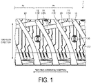
- FIG. 1 is a plan view of a road contact surface 3 of a tread portion 2 of the pneumatic tire 1 according to an embodiment.
- the pneumatic tire 1 illustrated in FIG. 1 includes the tread portion 2 disposed at the outermost portion of the pneumatic tire 1 in the tire radial direction.
- the surface of the tread portion 2, in other words, a portion that comes into contact with a road surface when a vehicle (not illustrated) equipped with the pneumatic tire 1 travels is formed as the road contact surface 3.
- a plurality of grooves 10 are formed in the road contact surface 3, and a plurality of land portions 15 are defined by a plurality of grooves 10.
- the grooves 10 include, for example, a plurality of circumferential grooves 11 extending in the tire circumferential direction and a plurality of lug grooves 12 extending in the tire width direction.
- the lug grooves 12 are inclined in the tire circumferential direction while extending in the tire width direction, and the circumferential grooves 11 are formed between adjacent lug grooves 12 in the tire circumferential direction.
- the land portions 15 are block-shaped by the circumferential grooves 11 and the lug grooves 12.
- a plurality of sipes 20 are formed in the road contact surface 3.
- the sipes 20 described herein are formed in a narrow groove shape in the ground contact surface 3.
- wall surfaces constituting the narrow groove do not contact one another, whereas in a case where the narrow groove is located in a portion of the ground contact surface formed on a flat plate in response to application of a load on the flat plate in the vertical direction or in a case where the land portion 15 provided with the narrow groove flexes, the wall surfaces constituting the narrow groove or at least parts of portions provided on the wall surface contact one another due to deformation of the land portion 15.
- regular rim refers to a standard rim defined by the Japan Automobile Tyre Manufacturers Association Inc. (JATMA), a "design rim” defined by the Tire and Rim Association, Inc. (TRA), or a “measuring rim” defined by the European Tyre and Rim Technical Organisation (ETRTO).
- a regular internal pressure refers to a "maximum air pressure” defined by JATMA, the maximum value in "TIRE LOAD LIMITS AT VARIOUS COLD INFLATION PRESSURES" defined by TRA, or “INFLATION PRESSURES” defined by ETRTO.
- the sipes 20 are formed extending in the tire width direction at a predetermined depth, and are provided in each of the land portions 15 defined by the grooves 10. Some of the sipes 20 bend in the tire circumferential direction while extending in the tire width direction and the sipes 20 vary in form. Additionally, the sipes 20 are disposed repeatedly in the tire circumferential direction in repeating patterns Pr corresponding to predetermined arrangement patterns.
- the repeating patterns Pr in this case are each configured by combining a plurality of the sipes 20, and have an equal shape of the sipes 20 constituting the repeating pattern Pr, an equal number of the sipes 20, and an equal relative positional relationship among the sipes 20.
- a plurality of the sipes 20 disposed in a range in which the length of the repeating pattern Pr in the tire circumferential direction is identical to the length of the interval between two lug grooves 12 are formed as one repeating pattern Pr.
- pin holes 30 are formed in the road contact surface 3 of the tread portion 2 and used as holes in which stud pins (not illustrated) are disposed.
- a plurality of the pin holes 30 are formed in the road contact surface 3 regardless of a tread pattern such as the repeating pattern Pr of the sipes 20.
- a tire molding die 100 will be described. Note that in the following description, the tire radial direction of the pneumatic tire 1 will be described as the tire radial direction in the tire molding die 100 and that the tire width direction of the pneumatic tire 1 will be described as the tire width direction of the tire molding die 100 and that the tire circumferential direction of the pneumatic tire 1 will be described as the tire circumferential direction in the tire molding die 100.
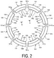
- FIG. 2 is an explanatory diagram of the tire molding die 100 for manufacturing the pneumatic tire 1 according to an embodiment.
- the tire molding die 100 is configured as a so-called sector mold corresponding to a divided tire molding die 100, and has an annular structure in which a plurality of sectors 101 separated from one another in the tire circumferential direction are connected to one another.
- the tire molding die 100 is illustrated in the form of an eight-division structure including eight sectors 101, but the number of divisions of the tire molding die 100 is not limited to eight.
- One sector 101 includes a plurality of pieces 103 for forming the tread portion 2 of the pneumatic tire 1 corresponding to a product, and a back block 104 in which the pieces 103 are mounted adjacent to one another.
- One piece 103 corresponds to a portion of the tread pattern divided at a constant pitch or any pitch, and includes a tread molding surface 102 for forming a part of the tread pattern.
- One sector 101 includes a plurality of pieces 103 in the tire circumferential direction and the tire width direction, respectively (not illustrated), and the plurality of pieces 103 are assembled to constitute the tread molding surface 102 of one sector 101. In other words, the piece 103 of one sector 101 is divided into a plurality of pieces 103.
- a plurality of pieces 103 are mounted and held in a predetermined arrangement.
- One sector 101 is thus configured.
- the tire molding die 100 is configured by using a plurality of the sectors 101 configured as described above and connecting the plurality of sectors 101 in an annular shape.
- the plurality of sectors 101 are connected together in an annular shape to assemble the tread molding surfaces 102 of the sectors 101, forming the tread molding surface 102 of the entire tread pattern.
- FIG. 3 is a view taken along A-A in FIG. 2 , and is an explanatory diagram of a state in which the sectors 101 are connected together.
- a plurality of circumferential groove forming bones 115 are disposed that form the circumferential grooves 11 in the tread portion 2 of the pneumatic tire 1
- a plurality of lug groove forming bones 116 are disposed that form the lug grooves 12
- a plurality of pin hole forming pins 117 are disposed that form the pin holes 30, and
- a plurality of sipe blades 120 are disposed that form the sipes 20.
- the circumferential groove forming bones 115 and the lug groove forming bones 116 are formed in a rib-like shape protruding from the tread molding surface 102, and the sipe blades 120 are formed as plate-like members formed from a metal material.
- stainless steel is used as the metal material that forms the sipe blade 120.
- the sipe blades 120 are disposed on the tread molding surface 102 such that the sipe blades 120 are identical in number to the sipes 20 formed in the tread portion 2.
- the sipe blades 120 are disposed at positions in the tread molding surface 102 corresponding to positions in the tread portion 2 where the sipes 20 are disposed.
- the sipe blades 120 are disposed repeatedly in the tire circumferential direction in the repeating pattern Pr corresponding to a predetermined arrangement pattern.
- a near sipe blade 121 corresponding to the sipe blade 120 located closest to a division position 101a between the sectors 101 and included in the plurality of sipe blades 120 disposed in one sector 101, is more rigid than an original shape blade 122.
- the division position 101a between the sectors 101 in this case is an end portion of the sector 101 in the tire circumferential direction, and corresponds to a position where the sectors 101 adjacent to each other in the tire circumferential direction are connected to each other.
- the near sipe blade 121 is typically disposed at a distance in a range of 10 mm from the division position 101a.
- the original shape blade 122 in this case is the sipe blade 120 located in the repeating pattern Pr differing from the repeating pattern Pr including the near sipe blade 121 at a position identical to the position of the near sipe blade 121 in the repeating pattern Pr including the near sipe blade 121.
- the original shape blade 122 is the sipe blade 120 disposed in the repeating pattern Pr differing from the repeating pattern Pr including the near sipe blade 121 at a position corresponding to the position of the near sipe blade 121 within the repeating pattern Pr including the near sipe blade 121.
- the sipe blade 120 located in the repeating pattern Pr differing from the repeating pattern Pr including the near sipe blade 121 at the position identical to the position of the near sipe blade 121 in the repeating pattern Pr including the near sipe blade 121 corresponds to another near sipe blade 121 differing from the near sipe blade 121, as the original shape blade 122, the sipe blade 120 located in further another repeating pattern Pr at the position identical to the position of the near sipe blade 121 in the repeating pattern Pr including the near sipe blade 121 is preferably used.
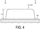
- FIG. 4 is a cross-sectional view taken along B-B in FIG. 3 , and is an explanatory diagram of the height of the near sipe blade 121.
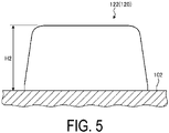
- FIG. 5 is a cross-sectional view taken along C-C in FIG. 3 and is an explanatory diagram of the height of the original shape blade 122.
- the maximum height HI of the near sipe blade 121 in the tire radial direction from the tread molding surface 102 is smaller than the maximum height H2 of the original shape blade 122 in the tire radial direction from the tread molding surface 102.
- the near sipe blade 121 and the original shape blade 122 are configured such that a ratio of the maximum height HI of the near sipe blade 121 to the maximum height H2 of the original shape blade 122 is in the range of 0.3 ⁇ (H1/H2) ⁇ 0.8.
- the maximum height HI of the near sipe blade 121 is smaller than the maximum height H2 of the original shape blade 122 as described above, and thus, the near sipe blade 121 is more rigid than the original shape blade 122.
- the height of the sipe blade 120 in the tire radial direction from the tread molding surface 102 is in the range of 1 mm or more and 15 mm or less.
- both the maximum height HI of the near sipe blade 121 and the maximum height H2 of the original shape blade 122 are in the range of 1 mm or more and 15 mm or less.
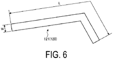
- FIG. 6 is a diagram taken along D-D in FIG. 4 .
- the near sipe blade 121 has a relationship between a sipe volume V corresponding to the volume of the near sipe blade 121 and the maximum height HI such that V ⁇ HI. That is, the near sipe blade 121 has a proportional relationship between the sipe volume V and the maximum height HI.
- the sipe volume V in this case is the product of the length L, the width W, and the maximum height HI of the near sipe blade 121.
- the length L of the near sipe blade 121 is a direction along the extension direction of the near sipe blade 121 or a length along the shape of the near sipe blade 121, in a case where the near sipe blade 121 is viewed in the height direction.
- the thickness of the sipe blade 120 is in the range of 0.2 mm or more and 1.0 mm or less.
- the near sipe blade 121 and the width W are also in the range of 0.2 mm or more and 1.0 mm or less.
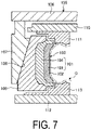
- FIG. 7 is an explanatory diagram illustrating a tire manufacturing method using the tire molding die 100 illustrated in FIG. 2 .
- FIG. 7 illustrates an axial cross-sectional view of the mold support device 105 including the tire molding die 100 illustrated in FIG. 2 .
- the pneumatic tire 1 according to the present embodiment is manufactured in accordance with manufacturing steps described below.
- various rubber members (not illustrated) that constitute the pneumatic tire 1, and members such as carcass plies (not illustrated) and belt plies (not illustrated) are applied to a molding machine to form a green tire G. Then, the green tire G is mounted on the mold support device 105 (see FIG. 7 ).
- the mold support device 105 includes a support plate 106, an outer ring 107, a segment 109, a top plate 110 and a base plate 112, an upper side mold 111 and a lower side mold 113, and the tire molding die 100.
- the support plate 106 has a disc shape and is disposed in a horizontal plane.
- the outer ring 107 is an annular structure having a tapered surface 108 on an inner side in the radial direction, and is mounted and suspended from a lower portion of an outer peripheral edge of the support plate 106.
- the segment 109 is a divisible annular structure corresponding to the sectors 101 of the tire molding die 100 and is inserted into the outer ring 107 and disposed slidably in the axial direction relative to the tapered surface 108 of the outer ring 107.
- the top plate 110 is installed movably in the axial direction inside the outer ring 107 and between the segment 109 and the support plate 106.
- the base plate 112 is disposed below the support plate 106 and at a position opposite the support plate 106 in the axial direction.
- the upper side mold 111 and the lower side mold 113 include molding surfaces with side profiles corresponding to both side surfaces of the pneumatic tire 1 in the tire width direction. Additionally, the upper side mold 111 and the lower side mold 113 are disposed such that the upper side mold 111 is attached to the lower surface side of the top plate 110, the lower side mold 113 is attached to the upper surface side of the base plate 112, and the molding surface of the upper side mold 111 faces the molding surface of the lower side mold 113.
- the tire molding die 100 has a divisible annular structure (see FIG. 2 ) with the tread molding surface 102 enabling a tread profile to be formed.
- the sectors 101 of the tire molding die 100 are attached to the inner circumferential surfaces of the corresponding segments 109, and the tire molding die 100 is disposed such that the tread molding surface 102 faces the side where the molding surfaces of the upper side mold 111 and the lower side mold 113 are located.
- the green tire G is mounted between the molding surface of the tire molding die 100 and the molding surfaces of the upper side mold 111 and the lower side mold 113.
- the support plate 106 moves downward in the axial direction to move the outer ring 107 downward in the axial direction along with the support plate 106, and the tapered surface 108 of the outer ring 107 pushes the segments 109 radially inward.
- the tire molding die 100 is contracted in diameter to annularly connect the molding surfaces of the sectors 101 of the tire molding die 100, and the entire molding surface of the tire molding die 100 is connected to the molding surface of the lower side mold 113.
- the top plate 110 moves downward in the axial direction to lower the upper side mold 111, reducing the distance between the upper side mold 111 and the lower side mold 113. Then, the entire molding surface of the tire molding die 100 is connected to the molding surface of the upper side mold 111. Accordingly, the green tire G is surrounded and held by the molding surface of the tire molding die 100, the molding surface of the upper side mold 111, and the molding surface of the lower side mold 113.
- the green tire G corresponding to an unvulcanized tire is subjected to vulcanization molding.
- the tire molding die 100 is heated, and the green tire G is expanded radially outward by a pressurizing device (not illustrated) and pressed against the tread molding surface 102 of the tire molding die 100.
- the green tire G is heated, and rubber molecules and sulfur molecules in the tread portion 2 are bonded together, leading to vulcanization.
- the tread molding surface 102 of the tire molding die 100 is transferred to the green tire G, forming the tread pattern in the tread portion 2.
- the tire after vulcanization molding is acquired as a product tire corresponding to the pneumatic tire 1 provided as a product.
- the support plate 106 and the top plate 110 move upward in the axial direction to space the tire molding die 100, the upper side mold 111, and the lower side mold 113 apart from one another, opening the mold support device 105.
- the tire detaches the tire molding die 100 from the mold support device 105 with the tire subjected to vulcanization molding.
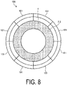
- FIG. 8 is an explanatory diagram illustrating a state before the tire molding die 100 is detached from the pneumatic tire 1 after vulcanization molding.
- the tread portion 2 is formed by the tire molding die 100.
- the tire molding die 100 is attached to the tread portion 2 of the pneumatic tire 1 (see FIG. 8 ).
- the plurality of sectors 101 of the tire molding die 100 are connected in an annular shape, and the tire molding die 100 is attached to the tread portion 2 of the pneumatic tire 1 immediately after vulcanization molding is performed.
- the plurality of sectors 101 connected together in an annular shape and attached to the tread portion 2 of the pneumatic tire 1 are detached from the pneumatic tire 1. Accordingly, the tire molding die 100 is detached from the pneumatic tire 1.
- FIG. 9 is an explanatory diagram illustrating a state in which the tire molding die 100 is detached from the pneumatic tire 1 after vulcanization molding.
- the sectors 101 are moved toward the outer side in the tire radial direction and separated from the tread portion 2 of the pneumatic tire 1. Accordingly, the tire molding die 100 is detached from the pneumatic tire 1.
- the plurality of sipe blades 120 disposed on the tread molding surfaces 102 of the sectors 101 of the tire molding die 100 form a plurality of sipes 20 in the road contact surface 3 of the tread portion 2.
- the plurality of sipe blades 120 disposed on the sectors 101 are extracted from the sipes 20 formed in the tread portion 2 of the pneumatic tire 1.
- the sipe blades 120 disposed on the tread molding surfaces 102 of the sector 101 extend from the tread molding surfaces 102 generally toward the inner side in the tire radial direction.
- the sectors 101 are moved toward the outer side in the tire radial direction.
- the direction in which the sipe blade 120 extends from the tread molding surface 102 is similar to the direction in which the sector 101 is moved.
- the direction in which the sipe blade 120 extends from the tread molding surface 102 is inclined with respect to the direction in which the sector 101 is moved.
- the direction in which the sector 101 is moved corresponds, even at or near the division position 101a between the sectors 101, to the direction in which a position in a central region of the sector 101 in the tire circumferential direction is moved toward the outer side in the tire radial direction.
- the direction of movement of the division position 101a between the sectors 101 during detachment of the sectors 101 from the pneumatic tire 1 differs from the tire radial direction, and thus, the direction in which the sipe blade 120 disposed at or near the division position 101a between the sectors 101 moves during detachment of the sectors 101 from the pneumatic tire 1 differs from the direction in which the sipe blades 120 extends from the tread molding surface 102.
- the direction of movement of the sipe blades 120 during detachment of the sectors 101 from the pneumatic tire 1 differs from the direction in which the sipe blades 120 extend from the tread molding surface 102
- the direction of movement of the sipe blades 120 differs from the depth direction of the sipes 20 formed by the sipe blades 120.
- a strong reaction force from the rubber member forming the sipes 20 acts on the sipe blades 120.
- a reaction force from the rubber member forming the sipes 20 acts on the sipe blade 120 disposed at or near the division position 101a between the sectors 101, and is likely to cause failure such as bending or breakage of the sipe blade 120.
- the near sipe blade 121 disposed at or near the division position 101a between the sectors 101 is more rigid than the original shape blade 122.
- the force during detachment of the sectors 101 from the pneumatic tire 1 acts in a direction differing from the depth direction of the sipe 20 formed by the near sipe blade 121, causing the reaction force from the rubber member forming the sipe 20 to act on the near sipe blade 121, possible failure in the near sipe blade 121 due to the reaction force can be suppressed.
- the durability of the sipe blades 120 can be improved.
- the near sipe blade 121 can be reliably made more rigid than the original shape blade 122.
- the maximum height HI of the near sipe blade 121 is smaller than the maximum height H2 of the original shape blade 122, during detachment of the sectors 101 from the pneumatic tire 1, the near sipe blade 121 can be pulled out of the sipe 20 earlier. This enables a reduction in the time for which the reaction force from the rubber member forming the sipes 20 acts on the near sipe blade 121.
- the sipes 20 can be formed that can reliably ensure performance on ice and snow and wet performance, and the durability of the sipe blades 120 can be reliably improved.
- the ratio of the maximum height HI of the near sipe blade 121 to the maximum height H2 of the original shape blade 122 is (H1/H2) ⁇ 0.3
- the maximum height HI of the near sipe blade 121 is excessively small, and this may lead to an excessively small depth of the sipe 20 formed by the near sipe blade 121.
- the sipes 20 contribute to ensuring performance on ice and snow and wet performance, but an excessively small depth of the sipe 20 may cause difficulty in ensuring performance on ice and snow and wet performance. Additionally, an excessively small depth of the sipe 20 formed by the near sipe blade 121 causes the sipe 20 to be worn earlier than the other sipes 20, and this may degrade the appearance. Additionally, in a case where the ratio of the maximum height HI of the near sipe blade 121 to the maximum height H2 of the original shape blade 122 is (H1/H2) > 0.8, the maximum height HI of the near sipe blade 121 is excessively large, and this may cause difficulty in making the near sipe blade 121 more rigid than the original shape blade 122.
- an excessively large maximum height HI of the near sipe blade 121 may cause difficulty in pulling the near sipe blade 121 early from the sipe 20 during detachment of the sectors 101 from the pneumatic tire 1, and this may in turn cause difficulty in shortening the time for which the reaction force from the rubber member forming the sipe 20 acts on the near sipe blade 121.
- the ratio of the maximum height HI of the near sipe blade 121 to the maximum height H2 of the original shape blade 122 is in the range of 0.3 ⁇ (H1/H2) ⁇ 0.8, the depth of the sipe 20 formed by the near sipe blade 121 can be ensured.
- performance on ice and snow and wet performance can be reliably ensured, and at the time of wear of the tread portion 2, degradation of the appearance can be suppressed.
- the near sipe blade 121 can be reliably made more rigid than the original shape blade 122, and the time for which the reaction force from the rubber member forming the sipe 20 acts on the near sipe blade 121 can be shortened during the detachment of the sectors 101 from the pneumatic tire 1, allowing failure in the near sipe blade 121 to be reliably suppressed.
- the sipes 20 can be formed that can reliably ensure performance on ice and snow and wet performance, and the durability of the sipe blades 120 can be reliably improved.
- the near sipe blade 121 can be reliably made more rigid.
- the near sipe blade 121 has a proportional relationship between the sipe volume V and the maximum height HI, the maximum height HI of the near sipe blade 121 decreases consistently with the length L and the width W.
- the near sipe blade 121 can be reliably made more rigid than the original shape blade 122, and bending of the near sipe blade 121 can be reliably suppressed. As a result, the durability of the sipe blades 120 can be reliably improved.
- the near sipe blade 121 and the original shape blade 122 are formed with identical shapes except for the maximum height, but may differ from each other in shapes other than the maximum height.
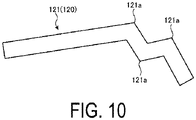
- FIG. 10 is a modified example of the tire molding die 100 according to an embodiment, and is a schematic plan view of the near sipe blade 121.
- FIG. 11 is a modified example of the tire molding die 100 according to an embodiment, and is a schematic plan view of the original shape blade 122.
- the near sipe blade 121 and the original shape blade 122 may be configured such that the number A1 of bend points 121a of the near sipe blade 121 differs from the number A2 of bend points 122a of the original shape blade 122.
- the relationship between the number A1 of bend points 121a of the near sipe blade 121 and the number A2 of the bend points 122a of the original shape blade 122 is preferably A2 ⁇ A1.
- the number A1 of the bend points 121a of the near sipe blade 121 is preferably greater than the number A2 of the bend points 122a of the original shape blade 122, for example, as illustrated in FIGS. 10 and 11 , the number A1 of the bend points 121a of the near sipe blade 121 is three, and the number A2 of the bend points 122a of the original shape blade 122 is one, and the like.
- the near sipe blade 121 can be reliably made more rigid than the original shape blade 122. Accordingly, failure in the near sipe blade 121 such as bending of the near sipe blade 121 can be reliably suppressed. As a result, the durability of the sipe blades 120 can be reliably improved.
- the number A1 of the bend points 121a of the near sipe blade 121 and the number A2 of the bend points 122a of the original shape blade 122 are preferably each in the range of 1 or more and 10 or less.
- the plurality of sipe blades 120 included in the tire molding die 100 are all made of an identical material, but the material may vary between sipe blades 120 as necessary.
- the near sipe blade 121 and the original shape blade 122 may differ from each other in material such that, for example, the relationship between the material strength S1 of the near sipe blade 121 and the material strength S2 of the original shape blade 122 is S2 ⁇ S1.
- the material strength S1 of the near sipe blade 121 and the material strength S2 of the original shape blade 122 include, for example, the tensile strength and hardness of the material forming the near sipe blade 121 and the original shape blade 122.
- the tensile strength of the material forming the near sipe blade 121 is preferably greater than the tensile strength of the material forming the original shape blade 122.
- the relationship between the material strength S1 of the near sipe blade 121 and the material strength S2 of the original shape blade 122 is S2 ⁇ S1, thus allowing the near sipe blade 121 to be reliably made more rigid than the original shape blade 122. Accordingly, failure in the near sipe blade 121 such as bending of the near sipe blade 121 can be reliably suppressed. As a result, the durability of the sipe blades 120 can be reliably improved.
- the near sipe blade 121 and the original shape blade 122 preferably have a relationship between the surface roughness R1 of the near sipe blade 121 and the surface roughness R2 of the original shape blade 122 such that R2 > R1.
- R1 of the near sipe blade 121 and the surface roughness R2 of the original shape blade 122 so-called arithmetic mean roughness Ra is used, for example. Because the surface roughness R1 of the near sipe blade 121 is smaller than the surface roughness R2 of the original shape blade 122, frictional resistance offered in response to pullout of the near sipe blade 121 from the sipe 20 can be made smaller than the frictional resistance offered in response to pullout of the original shape blade 122 from the sipe 20.
- the near sipe blade 121 can be easily pulled out from the sipe 20, and even in a case where the reaction force from the rubber member forming the sipe 20 acts on the near sipe blade 121, failure in the near sipe blade 121 such as bending of the near sipe blade 121 can be reliably suppressed. As a result, the durability of the sipe blades 120 can be reliably improved.
- the sipe 20 may be a closed sipe that is at both end portions terminated within the land portion 15 in the length direction of the sipe 20, or an open sipe that at both end portions opens into the groove 10 in the length direction of the sipe 20, or a semi-closed sipe that is at one end portion terminated within the land portion 15 and at the other end portion opens into the groove 10 in the length direction of the sipe 20.
- the pin holes 30 need not be formed in the tread portion 2 of the pneumatic tire 1, that is, the pin hole forming pins 117 need not be provided on the tire molding die 100.
- the tread pattern of the pneumatic tire 1 obtained by vulcanization molding using the tire molding die 100 is not limited to the tread pattern illustrated in the embodiment.
- FIG. 12 is a table showing results of performance evaluation tests of tire molding dies. In relation to the tire molding die 100 described above, the performance evaluation tests will be described that were conducted on a tire molding die of Conventional Example and the tire molding die 100 according to an embodiment of the present invention. The performance evaluation tests were conducted on the durability of the tire molding die.
- the performance evaluation tests were conducted by evaluating the durability of the tire molding die when the pneumatic tire 1 having a tire nominal size of 205/55R16 94T, defined by JATMA, was vulcanization molded using the tire molding die.
- the method for evaluating the durability of the tire molding die includes, after vulcanization molding of the pneumatic tire 1, checking the near sipe blades 121, which are likely to be bent, for bending, repairing the near sipe blades 121 bent by 5° or more, and measuring the number of the near sipe blades 121 repaired.
- the total number of the near sipe blades 121 repaired was calculated, and the reciprocals of the totals calculated were expressed as index values with the Conventional Example being assigned the value of 100. Larger values indicate a smaller number of the near sipe blade 121 repaired and superior mold durability.
- Conventional Example includes the near sipe blade 121 having rigidity comparable to the rigidity of the original shape blade 122.
- the near sipe blade 121 is more rigid than the original shape blade 122. Furthermore, the tire molding dies 100 according to Examples 1 to 8 differ in the maximum height HI of the near sipe blade 121, the ratio (H1/H2) of the maximum height HI of the near sipe blade 121 to the maximum height H2 of the original shape blade 122, whether the sipe volume V and the maximum height HI of the near sipe blade 121 are in a proportional relationship, the relative relationship between the number A1 of bend points 121a of the near sipe blade 121 and the number A2 of bend points 122a of the original shape blade 122, the relative relationship between the material strength S1 of the near sipe blade 121 and the material strength S2 of the original shape blade 122, and the relative relationship between the surface roughness R1 of the near sipe blade 121 and the surface roughness R2 of the original shape blade 122.
- the relative relationship between the material strength S1 of the near sipe blade 121 and the material strength S2 of the original shape blade 122 in the performance evaluation tests corresponds to the relative relationship between the tensile strength of the member forming the near sipe blade 121 and the tensile strength of the member forming the original shape blade 122.
- the results of the performance evaluation tests using these tire molding dies 100 indicate that, as shown in FIG. 12 , the tire molding dies 100 according to Examples 1 to 8 can suppress possible bending of the near sipe blade 121 and improve the durability of the near sipe blade 121 compared to Conventional Example. In other words, the tire molding dies 100 according to Examples 1 to 8 can improve the durability of the sipe blades 120.
Landscapes
- Engineering & Computer Science (AREA)
- Mechanical Engineering (AREA)
- Moulds For Moulding Plastics Or The Like (AREA)
- Heating, Cooling, Or Curing Plastics Or The Like In General (AREA)
Abstract
Description
- The present invention relates to a tire molding die and a pneumatic tire.
- Some known pneumatic tires are provided with so-called sipes, which are cuts formed in a tread portion, in order to improve performance on ice and snow, which is running performance on snowy roads and frozen road surfaces, and wet performance, which is running performance on wet road surfaces, and the like. For example, in studless tires, which are required to have running performance on icy and snowy road surfaces, a large number of sipes on the road contact surface of the tread portion are disposed. Additionally, the pneumatic tire is manufactured by vulcanization molding using a tire molding die divided into a plurality of sectors in the tire circumferential direction. However, various defects are likely to occur during vulcanization molding at division positions of sectors, and thus, some known tire molding dies are designed to eliminate such defects.
- For example, in a tire vulcanization mold described in
Patent Document 1, a turning point is provided on sipe blades disposed adjacent to the division positions of sectors. By modifying a portion from the turning point to the other end of the sipe blade further away from the division position than the original shape, separation of and damage to the sipe blade and the like are prevented during vulcanization release. Additionally, in a tire molding die described inPatent Document 2, by making the sipe volume of the sipe forming blade at the end portion position of the sector greater than the sipe volume of the sipe forming blade at the central portion position of the sector, uneven wear of a land portion at or near the division position of sectors is effectively suppressed. -
- Patent Document 1:
JP 2012-11690 A - Patent Document 2:
JP 2009-255734 A - In this regard, in a tire molding die in which sipe blades are disposed in each of the sectors separated from one another, the blades are likely to be twisted in a case where the tire is detached from the mold after vulcanization molding of the tire. In particular, because the twist occurring in the blades is significant at or near the division position of sectors, the twist may cause failure such as bending or breakage of the blades. As described above, in the known tire molding dies that include a plurality of the sectors separated from one another in the tire circumferential direction and in which the sipe blades are disposed, there is room for improvement in terms of durability due to the likelihood of failure in the blades disposed at or near the division position of sectors.
- In light of the foregoing, an object of the present invention is to provide a tire molding die and a pneumatic tire that can improve durability of sipe blades.
- In order to solve the problems and achieve the object described above, a tire molding die according to an embodiment of the present invention includes a plurality of sectors separated from one another in a tire circumferential direction, and a plurality of sipe blades disposed on tread molding surfaces of the sectors, the sipe blades are disposed repeatedly in the tire circumferential direction in a repeating pattern corresponding to a predetermined arrangement pattern, a near sipe blade that is included in a plurality of the sipe blades disposed in one of the sectors and that is closest to a division position between the sectors being more rigid than an original shape blade corresponding to the sipe blade provided in the repeating pattern differing from the repeating pattern including the near sipe blade at a position identical to a position of the near sipe blade in the repeating pattern including the near sipe blade.
- Additionally, in the tire molding die described above, preferably, a maximum height of the near sipe blade is smaller than a maximum height of the original shape blade.
- Additionally, in the tire molding die described above, preferably, a ratio of a maximum height HI of the near sipe blade to a maximum height H2 of the original shape blade is in a range 0.3 ≤ (H1/H2) ≤ 0.8.
- Additionally, in the tire molding die described above, preferably, the near sipe blade has a relationship between the maximum height HI and a sipe volume V corresponding to a product of a length L, a width W, and the maximum height HI of the near sipe blade such that V ∝ HI.
- Additionally, in the tire molding die described above, preferably, the near sipe blade and the original shape blade have a relationship between a number of bend points A1 of the near sipe blade and a number of bend points A2 of the original shape blade such that A2 < A1.
- Additionally, in the tire molding die described above, preferably, the near sipe blade and the original shape blade have a relationship between a material strength S1 of the near sipe blade and a material strength S2 of the original shape blade such that S2 < S1.
- Additionally, in the tire molding die described above, preferably, the near sipe blade and the original shape blade have a relationship between a surface roughness R1 of the near sipe blade and a surface roughness R2 of the original shape blade such that R2 > R1.
- In order to solve the problems described above and achieve the object, the pneumatic tire according to an embodiment of the present invention is vulcanized using the tire molding die described above.
- The tire molding die and pneumatic tire according to an embodiment of the present invention have the effect of improving the durability of the sipe blades.
-
-
FIG. 1 is a plan view illustrating a road contact surface of a tread portion of a pneumatic tire according to an embodiment. -
FIG. 2 is an explanatory diagram of a tire molding die for manufacturing a pneumatic tire according to an embodiment. -
FIG. 3 is a view taken along A-A inFIG. 2 and is an explanatory diagram of a state in which sectors are connected together. -
FIG. 4 is a cross-sectional view taken along B-B inFIG. 3 , and is an explanatory diagram of the height of a near sipe blade. -
FIG. 5 is a cross-sectional view taken along C-C inFIG. 3 , and is an explanatory diagram of the height of an original shape blade. -
FIG. 6 is a cross-sectional view taken along D-D inFIG. 4 . -
FIG. 7 is an explanatory diagram illustrating a tire manufacturing method using the tire molding die illustrated inFIG. 2 . -
FIG. 8 is an explanatory diagram illustrating a state before the tire molding die is detached from apneumatic tire 1 after vulcanization molding. -
FIG. 9 is an explanatory diagram illustrating a state in which the tire molding die is detached from the pneumatic tire after vulcanization molding. -
FIG. 10 is a schematic plan view of a near sipe blade in a modified example of the tire molding die according to an embodiment. -
FIG. 11 is a schematic plan view of an original shape blade in a modified example of the tire molding die according to an embodiment. -
FIG. 12 is a table showing results of performance evaluation tests of the tire molding die. - A tire molding die and a pneumatic tire according to embodiments of the present invention will be described in detail below with reference to the drawings. However, the present invention is not limited by the embodiment. Constituents of the following embodiments include elements that are essentially identical or that can be substituted or easily conceived of by a person skilled in the art.
- In the following description, the tire radial direction refers to a direction orthogonal to the rotation axis (not illustrated) of a
pneumatic tire 1, the inner side in the tire radial direction refers to the side facing the rotation axis in the tire radial direction, and the outer side in the tire radial direction refers to the side away from the rotation axis in the tire radial direction. Moreover, the tire circumferential direction refers to the circumferential direction with the rotation axis as the central axis. Additionally, the tire width direction refers to a direction parallel with the rotation axis, the inner side in the tire width direction refers to a side toward the tire equatorial plane (tire equator line) CL in the tire width direction, and the outer side in the tire width direction refers to a side away from the tire equatorial plane CL in the tire width direction. The tire equatorial plane CL is a plane that is orthogonal to the rotation axis of thepneumatic tire 1 and passes through the center of the tire width of thepneumatic tire 1, and in the tire equatorial plane CL, the center line in the tire width direction, which is the center position of thepneumatic tire 1 in the tire width direction, coincides with the position in the tire width direction. The tire width is the width in the tire width direction between portions located on the outermost sides in the tire width direction, or in other words, the distance between the portions that are the most distant from the tire equatorial plane CL in the tire width direction. The term "tire equator line" refers to a line in the tire circumferential direction of thepneumatic tire 1 that lies on the tire equatorial plane CL. -
FIG. 1 is a plan view of aroad contact surface 3 of atread portion 2 of thepneumatic tire 1 according to an embodiment. Thepneumatic tire 1 illustrated inFIG. 1 includes thetread portion 2 disposed at the outermost portion of thepneumatic tire 1 in the tire radial direction. The surface of thetread portion 2, in other words, a portion that comes into contact with a road surface when a vehicle (not illustrated) equipped with thepneumatic tire 1 travels is formed as theroad contact surface 3. A plurality ofgrooves 10 are formed in theroad contact surface 3, and a plurality ofland portions 15 are defined by a plurality ofgrooves 10. Thegrooves 10 include, for example, a plurality ofcircumferential grooves 11 extending in the tire circumferential direction and a plurality oflug grooves 12 extending in the tire width direction. In the present embodiment, thelug grooves 12 are inclined in the tire circumferential direction while extending in the tire width direction, and thecircumferential grooves 11 are formed betweenadjacent lug grooves 12 in the tire circumferential direction. Theland portions 15 are block-shaped by thecircumferential grooves 11 and thelug grooves 12. - Additionally, a plurality of
sipes 20 are formed in theroad contact surface 3. Thesipes 20 described herein are formed in a narrow groove shape in theground contact surface 3. In thesipes 20, when thepneumatic tire 1 is mounted on a regular rim, inflated to a regular internal pressure, and in an unloaded state, wall surfaces constituting the narrow groove do not contact one another, whereas in a case where the narrow groove is located in a portion of the ground contact surface formed on a flat plate in response to application of a load on the flat plate in the vertical direction or in a case where theland portion 15 provided with the narrow groove flexes, the wall surfaces constituting the narrow groove or at least parts of portions provided on the wall surface contact one another due to deformation of theland portion 15. Here, "regular rim" refers to a standard rim defined by the Japan Automobile Tyre Manufacturers Association Inc. (JATMA), a "design rim" defined by the Tire and Rim Association, Inc. (TRA), or a "measuring rim" defined by the European Tyre and Rim Technical Organisation (ETRTO). Moreover, a regular internal pressure refers to a "maximum air pressure" defined by JATMA, the maximum value in "TIRE LOAD LIMITS AT VARIOUS COLD INFLATION PRESSURES" defined by TRA, or "INFLATION PRESSURES" defined by ETRTO. - The
sipes 20 are formed extending in the tire width direction at a predetermined depth, and are provided in each of theland portions 15 defined by thegrooves 10. Some of thesipes 20 bend in the tire circumferential direction while extending in the tire width direction and thesipes 20 vary in form. Additionally, thesipes 20 are disposed repeatedly in the tire circumferential direction in repeating patterns Pr corresponding to predetermined arrangement patterns. The repeating patterns Pr in this case are each configured by combining a plurality of thesipes 20, and have an equal shape of thesipes 20 constituting the repeating pattern Pr, an equal number of thesipes 20, and an equal relative positional relationship among thesipes 20. In the present embodiment, a plurality of thesipes 20 disposed in a range in which the length of the repeating pattern Pr in the tire circumferential direction is identical to the length of the interval between twolug grooves 12 are formed as one repeating pattern Pr. - Additionally, pin holes 30 are formed in the
road contact surface 3 of thetread portion 2 and used as holes in which stud pins (not illustrated) are disposed. A plurality of the pin holes 30 are formed in theroad contact surface 3 regardless of a tread pattern such as the repeating pattern Pr of thesipes 20. - Now, a tire molding die 100 according to the embodiment will be described. Note that in the following description, the tire radial direction of the
pneumatic tire 1 will be described as the tire radial direction in the tire molding die 100 and that the tire width direction of thepneumatic tire 1 will be described as the tire width direction of the tire molding die 100 and that the tire circumferential direction of thepneumatic tire 1 will be described as the tire circumferential direction in the tire molding die 100. -
FIG. 2 is an explanatory diagram of the tire molding die 100 for manufacturing thepneumatic tire 1 according to an embodiment. As illustrated inFIG. 2 , the tire molding die 100 is configured as a so-called sector mold corresponding to a divided tire molding die 100, and has an annular structure in which a plurality ofsectors 101 separated from one another in the tire circumferential direction are connected to one another. Note that inFIG. 2 , the tire molding die 100 is illustrated in the form of an eight-division structure including eightsectors 101, but the number of divisions of the tire molding die 100 is not limited to eight. - One
sector 101 includes a plurality ofpieces 103 for forming thetread portion 2 of thepneumatic tire 1 corresponding to a product, and aback block 104 in which thepieces 103 are mounted adjacent to one another. Onepiece 103 corresponds to a portion of the tread pattern divided at a constant pitch or any pitch, and includes atread molding surface 102 for forming a part of the tread pattern. Onesector 101 includes a plurality ofpieces 103 in the tire circumferential direction and the tire width direction, respectively (not illustrated), and the plurality ofpieces 103 are assembled to constitute thetread molding surface 102 of onesector 101. In other words, thepiece 103 of onesector 101 is divided into a plurality ofpieces 103. - In the
back block 104, a plurality ofpieces 103 are mounted and held in a predetermined arrangement. Onesector 101 is thus configured. - The tire molding die 100 is configured by using a plurality of the
sectors 101 configured as described above and connecting the plurality ofsectors 101 in an annular shape. In the tire molding die 100, the plurality ofsectors 101 are connected together in an annular shape to assemble the tread molding surfaces 102 of thesectors 101, forming thetread molding surface 102 of the entire tread pattern. -
FIG. 3 is a view taken along A-A inFIG. 2 , and is an explanatory diagram of a state in which thesectors 101 are connected together. In thetread molding surface 102 in eachsector 101, a plurality of circumferentialgroove forming bones 115 are disposed that form thecircumferential grooves 11 in thetread portion 2 of thepneumatic tire 1, a plurality of luggroove forming bones 116 are disposed that form thelug grooves 12, a plurality of pinhole forming pins 117 are disposed that form the pin holes 30, and a plurality ofsipe blades 120 are disposed that form thesipes 20. In this regard, the circumferentialgroove forming bones 115 and the luggroove forming bones 116 are formed in a rib-like shape protruding from thetread molding surface 102, and thesipe blades 120 are formed as plate-like members formed from a metal material. For example, stainless steel is used as the metal material that forms thesipe blade 120. - Additionally, the
sipe blades 120 are disposed on thetread molding surface 102 such that thesipe blades 120 are identical in number to thesipes 20 formed in thetread portion 2. Thesipe blades 120 are disposed at positions in thetread molding surface 102 corresponding to positions in thetread portion 2 where thesipes 20 are disposed. Thus, like thesipes 20 formed in thetread portion 2 of thepneumatic tire 1, thesipe blades 120 are disposed repeatedly in the tire circumferential direction in the repeating pattern Pr corresponding to a predetermined arrangement pattern. - A
near sipe blade 121, corresponding to thesipe blade 120 located closest to adivision position 101a between thesectors 101 and included in the plurality ofsipe blades 120 disposed in onesector 101, is more rigid than anoriginal shape blade 122. Thedivision position 101a between thesectors 101 in this case is an end portion of thesector 101 in the tire circumferential direction, and corresponds to a position where thesectors 101 adjacent to each other in the tire circumferential direction are connected to each other. Additionally, thenear sipe blade 121 is typically disposed at a distance in a range of 10 mm from thedivision position 101a. - In addition, the
original shape blade 122 in this case is thesipe blade 120 located in the repeating pattern Pr differing from the repeating pattern Pr including thenear sipe blade 121 at a position identical to the position of thenear sipe blade 121 in the repeating pattern Pr including thenear sipe blade 121. In other words, theoriginal shape blade 122 is thesipe blade 120 disposed in the repeating pattern Pr differing from the repeating pattern Pr including thenear sipe blade 121 at a position corresponding to the position of thenear sipe blade 121 within the repeating pattern Pr including thenear sipe blade 121. - Note that in a case where the
sipe blade 120 located in the repeating pattern Pr differing from the repeating pattern Pr including thenear sipe blade 121 at the position identical to the position of thenear sipe blade 121 in the repeating pattern Pr including thenear sipe blade 121 corresponds to anothernear sipe blade 121 differing from thenear sipe blade 121, as theoriginal shape blade 122, thesipe blade 120 located in further another repeating pattern Pr at the position identical to the position of thenear sipe blade 121 in the repeating pattern Pr including thenear sipe blade 121 is preferably used. -
FIG. 4 is a cross-sectional view taken along B-B inFIG. 3 , and is an explanatory diagram of the height of thenear sipe blade 121.FIG. 5 is a cross-sectional view taken along C-C inFIG. 3 and is an explanatory diagram of the height of theoriginal shape blade 122. The maximum height HI of thenear sipe blade 121 in the tire radial direction from thetread molding surface 102 is smaller than the maximum height H2 of theoriginal shape blade 122 in the tire radial direction from thetread molding surface 102. Specifically, thenear sipe blade 121 and theoriginal shape blade 122 are configured such that a ratio of the maximum height HI of thenear sipe blade 121 to the maximum height H2 of theoriginal shape blade 122 is in the range of 0.3 ≤ (H1/H2) ≤ 0.8. The maximum height HI of thenear sipe blade 121 is smaller than the maximum height H2 of theoriginal shape blade 122 as described above, and thus, thenear sipe blade 121 is more rigid than theoriginal shape blade 122. - Note that in the present embodiment, the height of the
sipe blade 120 in the tire radial direction from thetread molding surface 102 is in the range of 1 mm or more and 15 mm or less. Thus, both the maximum height HI of thenear sipe blade 121 and the maximum height H2 of theoriginal shape blade 122 are in the range of 1 mm or more and 15 mm or less. -
FIG. 6 is a diagram taken along D-D inFIG. 4 . Thenear sipe blade 121 has a relationship between a sipe volume V corresponding to the volume of thenear sipe blade 121 and the maximum height HI such that V α HI. That is, thenear sipe blade 121 has a proportional relationship between the sipe volume V and the maximum height HI. The sipe volume V in this case is the product of the length L, the width W, and the maximum height HI of thenear sipe blade 121. The length L of thenear sipe blade 121 is a direction along the extension direction of thenear sipe blade 121 or a length along the shape of thenear sipe blade 121, in a case where thenear sipe blade 121 is viewed in the height direction. - Note that in the present embodiment, the thickness of the
sipe blade 120 is in the range of 0.2 mm or more and 1.0 mm or less. Thus, thenear sipe blade 121 and the width W are also in the range of 0.2 mm or more and 1.0 mm or less. - Now, a manufacturing method for the
pneumatic tire 1 using the tire molding die 100 according to an embodiment will be described.FIG. 7 is an explanatory diagram illustrating a tire manufacturing method using the tire molding die 100 illustrated inFIG. 2 .FIG. 7 illustrates an axial cross-sectional view of themold support device 105 including the tire molding die 100 illustrated inFIG. 2 . Thepneumatic tire 1 according to the present embodiment is manufactured in accordance with manufacturing steps described below. - First, various rubber members (not illustrated) that constitute the
pneumatic tire 1, and members such as carcass plies (not illustrated) and belt plies (not illustrated) are applied to a molding machine to form a green tire G. Then, the green tire G is mounted on the mold support device 105 (seeFIG. 7 ). - In
FIG. 7 , themold support device 105 includes asupport plate 106, anouter ring 107, asegment 109, atop plate 110 and abase plate 112, anupper side mold 111 and alower side mold 113, and the tire molding die 100. Thesupport plate 106 has a disc shape and is disposed in a horizontal plane. Theouter ring 107 is an annular structure having a taperedsurface 108 on an inner side in the radial direction, and is mounted and suspended from a lower portion of an outer peripheral edge of thesupport plate 106. Thesegment 109 is a divisible annular structure corresponding to thesectors 101 of the tire molding die 100 and is inserted into theouter ring 107 and disposed slidably in the axial direction relative to the taperedsurface 108 of theouter ring 107. Thetop plate 110 is installed movably in the axial direction inside theouter ring 107 and between thesegment 109 and thesupport plate 106. Thebase plate 112 is disposed below thesupport plate 106 and at a position opposite thesupport plate 106 in the axial direction. - The
upper side mold 111 and thelower side mold 113 include molding surfaces with side profiles corresponding to both side surfaces of thepneumatic tire 1 in the tire width direction. Additionally, theupper side mold 111 and thelower side mold 113 are disposed such that theupper side mold 111 is attached to the lower surface side of thetop plate 110, thelower side mold 113 is attached to the upper surface side of thebase plate 112, and the molding surface of theupper side mold 111 faces the molding surface of thelower side mold 113. As described above, the tire molding die 100 has a divisible annular structure (seeFIG. 2 ) with thetread molding surface 102 enabling a tread profile to be formed. Additionally, thesectors 101 of the tire molding die 100 are attached to the inner circumferential surfaces of the correspondingsegments 109, and the tire molding die 100 is disposed such that thetread molding surface 102 faces the side where the molding surfaces of theupper side mold 111 and thelower side mold 113 are located. - Then, the green tire G is mounted between the molding surface of the tire molding die 100 and the molding surfaces of the
upper side mold 111 and thelower side mold 113. At this time, thesupport plate 106 moves downward in the axial direction to move theouter ring 107 downward in the axial direction along with thesupport plate 106, and thetapered surface 108 of theouter ring 107 pushes thesegments 109 radially inward. Then, the tire molding die 100 is contracted in diameter to annularly connect the molding surfaces of thesectors 101 of the tire molding die 100, and the entire molding surface of the tire molding die 100 is connected to the molding surface of thelower side mold 113. Additionally, thetop plate 110 moves downward in the axial direction to lower theupper side mold 111, reducing the distance between theupper side mold 111 and thelower side mold 113. Then, the entire molding surface of the tire molding die 100 is connected to the molding surface of theupper side mold 111. Accordingly, the green tire G is surrounded and held by the molding surface of the tire molding die 100, the molding surface of theupper side mold 111, and the molding surface of thelower side mold 113. - Then, the green tire G corresponding to an unvulcanized tire is subjected to vulcanization molding. Specifically, the tire molding die 100 is heated, and the green tire G is expanded radially outward by a pressurizing device (not illustrated) and pressed against the
tread molding surface 102 of the tire molding die 100. Then, the green tire G is heated, and rubber molecules and sulfur molecules in thetread portion 2 are bonded together, leading to vulcanization. Then, thetread molding surface 102 of the tire molding die 100 is transferred to the green tire G, forming the tread pattern in thetread portion 2. - Subsequently, the tire after vulcanization molding is acquired as a product tire corresponding to the
pneumatic tire 1 provided as a product. At this time, thesupport plate 106 and thetop plate 110 move upward in the axial direction to space the tire molding die 100, theupper side mold 111, and thelower side mold 113 apart from one another, opening themold support device 105. In response to opening of themold support device 105, the tire detaches the tire molding die 100 from themold support device 105 with the tire subjected to vulcanization molding. -
FIG. 8 is an explanatory diagram illustrating a state before the tire molding die 100 is detached from thepneumatic tire 1 after vulcanization molding. During vulcanization molding of thepneumatic tire 1 using the tire molding die 100, thetread portion 2 is formed by the tire molding die 100. Thus, immediately after vulcanization molding is performed, the tire molding die 100 is attached to thetread portion 2 of the pneumatic tire 1 (seeFIG. 8 ). Specifically, the plurality ofsectors 101 of the tire molding die 100 are connected in an annular shape, and the tire molding die 100 is attached to thetread portion 2 of thepneumatic tire 1 immediately after vulcanization molding is performed. In response to completion of the vulcanization molding of thepneumatic tire 1 and detachment, by the tire, of the tire molding die 100 from themold support device 105, the plurality ofsectors 101 connected together in an annular shape and attached to thetread portion 2 of thepneumatic tire 1 are detached from thepneumatic tire 1. Accordingly, the tire molding die 100 is detached from thepneumatic tire 1. -
FIG. 9 is an explanatory diagram illustrating a state in which the tire molding die 100 is detached from thepneumatic tire 1 after vulcanization molding. In a case that the plurality ofsectors 101 are detached from thepneumatic tire 1, thesectors 101 are moved toward the outer side in the tire radial direction and separated from thetread portion 2 of thepneumatic tire 1. Accordingly, the tire molding die 100 is detached from thepneumatic tire 1. In this case, during vulcanization molding of thepneumatic tire 1, the plurality ofsipe blades 120 disposed on the tread molding surfaces 102 of thesectors 101 of the tire molding die 100 form a plurality ofsipes 20 in theroad contact surface 3 of thetread portion 2. In response to detachment of thesectors 101 of the tire molding die 100 from thepneumatic tire 1 by moving thesectors 101 toward the outer side in the tire radial direction, the plurality ofsipe blades 120 disposed on thesectors 101 are extracted from thesipes 20 formed in thetread portion 2 of thepneumatic tire 1. - In this regard, the
sipe blades 120 disposed on the tread molding surfaces 102 of thesector 101 extend from the tread molding surfaces 102 generally toward the inner side in the tire radial direction. On the other hand, in a case of detaching thesectors 101 from thepneumatic tire 1, thesectors 101 are moved toward the outer side in the tire radial direction. Thus, for thesipe blade 120 that is included in the plurality ofsipe blades 120 disposed on onesector 101 and that is disposed in a central region of thesector 101 in the tire circumferential direction, the direction in which thesipe blade 120 extends from thetread molding surface 102 is similar to the direction in which thesector 101 is moved. - In contrast, for the
sipe blade 120 that is included in the plurality ofsipe blades 120 disposed on onesector 101 and that is disposed at or near thedivision position 101a between thesectors 101, the direction in which thesipe blade 120 extends from thetread molding surface 102 is inclined with respect to the direction in which thesector 101 is moved. In other words, in a case where thesectors 101 are detached from thepneumatic tire 1, onesector 101 is integrally moved, and thus, the direction in which thesector 101 is moved corresponds, even at or near thedivision position 101a between thesectors 101, to the direction in which a position in a central region of thesector 101 in the tire circumferential direction is moved toward the outer side in the tire radial direction. Thus, the direction of movement of thedivision position 101a between thesectors 101 during detachment of thesectors 101 from thepneumatic tire 1 differs from the tire radial direction, and thus, the direction in which thesipe blade 120 disposed at or near thedivision position 101a between thesectors 101 moves during detachment of thesectors 101 from thepneumatic tire 1 differs from the direction in which thesipe blades 120 extends from thetread molding surface 102. - In a case where the direction of movement of the
sipe blades 120 during detachment of thesectors 101 from thepneumatic tire 1 differs from the direction in which thesipe blades 120 extend from thetread molding surface 102, the direction of movement of thesipe blades 120 differs from the depth direction of thesipes 20 formed by thesipe blades 120. In this case, because the force acts on thesipe blades 120 in a direction differing from the depth direction of thesipes 20 during movement of thesectors 101, a strong reaction force from the rubber member forming thesipes 20 acts on thesipe blades 120. In a case of detachment of thesectors 101 from thepneumatic tire 1, a reaction force from the rubber member forming thesipes 20 acts on thesipe blade 120 disposed at or near thedivision position 101a between thesectors 101, and is likely to cause failure such as bending or breakage of thesipe blade 120. - Such failure is likely to occur in the
sipe blade 120 disposed at or near thedivision position 101a between thesectors 101 during detachment of thesectors 101. However, in the tire molding die 100 according to the present embodiment, thenear sipe blade 121 disposed at or near thedivision position 101a between thesectors 101 is more rigid than theoriginal shape blade 122. Thus, even in a case where the force during detachment of thesectors 101 from thepneumatic tire 1 acts in a direction differing from the depth direction of thesipe 20 formed by thenear sipe blade 121, causing the reaction force from the rubber member forming thesipe 20 to act on thenear sipe blade 121, possible failure in thenear sipe blade 121 due to the reaction force can be suppressed. As a result, the durability of thesipe blades 120 can be improved. - Additionally, because the maximum height HI of the
near sipe blade 121 is smaller than the maximum height H2 of theoriginal shape blade 122, thenear sipe blade 121 can be reliably made more rigid than theoriginal shape blade 122. In addition, because the maximum height HI of thenear sipe blade 121 is smaller than the maximum height H2 of theoriginal shape blade 122, during detachment of thesectors 101 from thepneumatic tire 1, thenear sipe blade 121 can be pulled out of thesipe 20 earlier. This enables a reduction in the time for which the reaction force from the rubber member forming thesipes 20 acts on thenear sipe blade 121. Consequently, failure in thenear sipe blade 121 such as bending of thenear sipe blade 121 can be reliably suppressed, which failure is caused by the force acting on thenear sipe blade 121 during detachment of thesectors 101 from thepneumatic tire 1. As a result, the durability of thesipe blades 120 can be reliably improved. - Additionally, because the ratio of the maximum height HI of the
near sipe blade 121 to the maximum height H2 of theoriginal shape blade 122 is in the range of 0.3 ≤ (H1/H2) ≤ 0.8, thesipes 20 can be formed that can reliably ensure performance on ice and snow and wet performance, and the durability of thesipe blades 120 can be reliably improved. Specifically, in a case where the ratio of the maximum height HI of thenear sipe blade 121 to the maximum height H2 of theoriginal shape blade 122 is (H1/H2) < 0.3, the maximum height HI of thenear sipe blade 121 is excessively small, and this may lead to an excessively small depth of thesipe 20 formed by thenear sipe blade 121. Thesipes 20 contribute to ensuring performance on ice and snow and wet performance, but an excessively small depth of thesipe 20 may cause difficulty in ensuring performance on ice and snow and wet performance. Additionally, an excessively small depth of thesipe 20 formed by thenear sipe blade 121 causes thesipe 20 to be worn earlier than theother sipes 20, and this may degrade the appearance. Additionally, in a case where the ratio of the maximum height HI of thenear sipe blade 121 to the maximum height H2 of theoriginal shape blade 122 is (H1/H2) > 0.8, the maximum height HI of thenear sipe blade 121 is excessively large, and this may cause difficulty in making thenear sipe blade 121 more rigid than theoriginal shape blade 122. Additionally, an excessively large maximum height HI of thenear sipe blade 121 may cause difficulty in pulling thenear sipe blade 121 early from thesipe 20 during detachment of thesectors 101 from thepneumatic tire 1, and this may in turn cause difficulty in shortening the time for which the reaction force from the rubber member forming thesipe 20 acts on thenear sipe blade 121. - In contrast, in a case where the ratio of the maximum height HI of the
near sipe blade 121 to the maximum height H2 of theoriginal shape blade 122 is in the range of 0.3 ≤ (H1/H2) ≤ 0.8, the depth of thesipe 20 formed by thenear sipe blade 121 can be ensured. Thus, performance on ice and snow and wet performance can be reliably ensured, and at the time of wear of thetread portion 2, degradation of the appearance can be suppressed. Furthermore, thenear sipe blade 121 can be reliably made more rigid than theoriginal shape blade 122, and the time for which the reaction force from the rubber member forming thesipe 20 acts on thenear sipe blade 121 can be shortened during the detachment of thesectors 101 from thepneumatic tire 1, allowing failure in thenear sipe blade 121 to be reliably suppressed. As a result, thesipes 20 can be formed that can reliably ensure performance on ice and snow and wet performance, and the durability of thesipe blades 120 can be reliably improved. - In addition, because the relationship between the sipe volume V and the maximum height HI is V α HI in the
near sipe blade 121, thenear sipe blade 121 can be reliably made more rigid. In other words, because thenear sipe blade 121 has a proportional relationship between the sipe volume V and the maximum height HI, the maximum height HI of thenear sipe blade 121 decreases consistently with the length L and the width W. Thus, thenear sipe blade 121 can be reliably made more rigid than theoriginal shape blade 122, and bending of thenear sipe blade 121 can be reliably suppressed. As a result, the durability of thesipe blades 120 can be reliably improved. - Note that in the embodiment described above, the
near sipe blade 121 and theoriginal shape blade 122 are formed with identical shapes except for the maximum height, but may differ from each other in shapes other than the maximum height.FIG. 10 is a modified example of the tire molding die 100 according to an embodiment, and is a schematic plan view of thenear sipe blade 121.FIG. 11 is a modified example of the tire molding die 100 according to an embodiment, and is a schematic plan view of theoriginal shape blade 122. Thenear sipe blade 121 and theoriginal shape blade 122 may be configured such that the number A1 ofbend points 121a of thenear sipe blade 121 differs from the number A2 ofbend points 122a of theoriginal shape blade 122. In this case, the relationship between the number A1 ofbend points 121a of thenear sipe blade 121 and the number A2 of the bend points 122a of theoriginal shape blade 122 is preferably A2 < A1. - The number A1 of the bend points 121a of the
near sipe blade 121 is preferably greater than the number A2 of the bend points 122a of theoriginal shape blade 122, for example, as illustrated inFIGS. 10 and11 , the number A1 of the bend points 121a of thenear sipe blade 121 is three, and the number A2 of the bend points 122a of theoriginal shape blade 122 is one, and the like. By making the number A1 of the bend points 121a of thenear sipe blade 121 greater than the number A2 of the bend points 122a of theoriginal shape blade 122, thenear sipe blade 121 can be reliably made more rigid than theoriginal shape blade 122. Accordingly, failure in thenear sipe blade 121 such as bending of thenear sipe blade 121 can be reliably suppressed. As a result, the durability of thesipe blades 120 can be reliably improved. - Note that the number A1 of the bend points 121a of the
near sipe blade 121 and the number A2 of the bend points 122a of theoriginal shape blade 122 are preferably each in the range of 1 or more and 10 or less. - Additionally, in the embodiment described above, the plurality of
sipe blades 120 included in the tire molding die 100 are all made of an identical material, but the material may vary betweensipe blades 120 as necessary. Thenear sipe blade 121 and theoriginal shape blade 122 may differ from each other in material such that, for example, the relationship between the material strength S1 of thenear sipe blade 121 and the material strength S2 of theoriginal shape blade 122 is S2 < S1. In this case, the material strength S1 of thenear sipe blade 121 and the material strength S2 of theoriginal shape blade 122 include, for example, the tensile strength and hardness of the material forming thenear sipe blade 121 and theoriginal shape blade 122. Thus, in a case where, for example, tensile strength is used as the material strength compared between thenear sipe blade 121 and theoriginal shape blade 122, the tensile strength of the material forming thenear sipe blade 121 is preferably greater than the tensile strength of the material forming theoriginal shape blade 122. - In this way, the relationship between the material strength S1 of the
near sipe blade 121 and the material strength S2 of theoriginal shape blade 122 is S2 < S1, thus allowing thenear sipe blade 121 to be reliably made more rigid than theoriginal shape blade 122. Accordingly, failure in thenear sipe blade 121 such as bending of thenear sipe blade 121 can be reliably suppressed. As a result, the durability of thesipe blades 120 can be reliably improved. - Additionally, the
near sipe blade 121 and theoriginal shape blade 122 preferably have a relationship between the surface roughness R1 of thenear sipe blade 121 and the surface roughness R2 of theoriginal shape blade 122 such that R2 > R1.In this case, as the surface roughness R1 of thenear sipe blade 121 and the surface roughness R2 of theoriginal shape blade 122, so-called arithmetic mean roughness Ra is used, for example. Because the surface roughness R1 of thenear sipe blade 121 is smaller than the surface roughness R2 of theoriginal shape blade 122, frictional resistance offered in response to pullout of thenear sipe blade 121 from thesipe 20 can be made smaller than the frictional resistance offered in response to pullout of theoriginal shape blade 122 from thesipe 20. Thus, in a case where thesectors 101 of the tire molding die 100 are detached from thepneumatic tire 1 after vulcanization molding, thenear sipe blade 121 can be easily pulled out from thesipe 20, and even in a case where the reaction force from the rubber member forming thesipe 20 acts on thenear sipe blade 121, failure in thenear sipe blade 121 such as bending of thenear sipe blade 121 can be reliably suppressed. As a result, the durability of thesipe blades 120 can be reliably improved. - Additionally, the
sipe 20 may be a closed sipe that is at both end portions terminated within theland portion 15 in the length direction of thesipe 20, or an open sipe that at both end portions opens into thegroove 10 in the length direction of thesipe 20, or a semi-closed sipe that is at one end portion terminated within theland portion 15 and at the other end portion opens into thegroove 10 in the length direction of thesipe 20. Additionally, the pin holes 30 need not be formed in thetread portion 2 of thepneumatic tire 1, that is, the pinhole forming pins 117 need not be provided on the tire molding die 100. Additionally, the tread pattern of thepneumatic tire 1 obtained by vulcanization molding using the tire molding die 100 is not limited to the tread pattern illustrated in the embodiment. -
FIG. 12 is a table showing results of performance evaluation tests of tire molding dies. In relation to the tire molding die 100 described above, the performance evaluation tests will be described that were conducted on a tire molding die of Conventional Example and the tire molding die 100 according to an embodiment of the present invention. The performance evaluation tests were conducted on the durability of the tire molding die. - The performance evaluation tests were conducted by evaluating the durability of the tire molding die when the
pneumatic tire 1 having a tire nominal size of 205/55R16 94T, defined by JATMA, was vulcanization molded using the tire molding die. The method for evaluating the durability of the tire molding die includes, after vulcanization molding of thepneumatic tire 1, checking thenear sipe blades 121, which are likely to be bent, for bending, repairing thenear sipe blades 121 bent by 5° or more, and measuring the number of thenear sipe blades 121 repaired. Furthermore, after vulcanization molding was performed 5000 times, the total number of thenear sipe blades 121 repaired was calculated, and the reciprocals of the totals calculated were expressed as index values with the Conventional Example being assigned the value of 100. Larger values indicate a smaller number of thenear sipe blade 121 repaired and superior mold durability. - The performance evaluation tests were conducted on nine types of tire molding dies including a pneumatic tire of Conventional Example as an example of the known tire molding die and Examples 1 to 8 of the tire molding die 100 according to an embodiment of the present invention. Among the tire molding dies, Conventional Example includes the
near sipe blade 121 having rigidity comparable to the rigidity of theoriginal shape blade 122. - In contrast, in all of Examples 1 to 8, corresponding to examples of the tire molding die 100 according to the present invention, the
near sipe blade 121 is more rigid than theoriginal shape blade 122. Furthermore, the tire molding dies 100 according to Examples 1 to 8 differ in the maximum height HI of thenear sipe blade 121, the ratio (H1/H2) of the maximum height HI of thenear sipe blade 121 to the maximum height H2 of theoriginal shape blade 122, whether the sipe volume V and the maximum height HI of thenear sipe blade 121 are in a proportional relationship, the relative relationship between the number A1 ofbend points 121a of thenear sipe blade 121 and the number A2 ofbend points 122a of theoriginal shape blade 122, the relative relationship between the material strength S1 of thenear sipe blade 121 and the material strength S2 of theoriginal shape blade 122, and the relative relationship between the surface roughness R1 of thenear sipe blade 121 and the surface roughness R2 of theoriginal shape blade 122. - Note that the relative relationship between the material strength S1 of the
near sipe blade 121 and the material strength S2 of theoriginal shape blade 122 in the performance evaluation tests corresponds to the relative relationship between the tensile strength of the member forming thenear sipe blade 121 and the tensile strength of the member forming theoriginal shape blade 122. - The results of the performance evaluation tests using these tire molding dies 100 indicate that, as shown in
FIG. 12 , the tire molding dies 100 according to Examples 1 to 8 can suppress possible bending of thenear sipe blade 121 and improve the durability of thenear sipe blade 121 compared to Conventional Example. In other words, the tire molding dies 100 according to Examples 1 to 8 can improve the durability of thesipe blades 120. -
- 1 Pneumatic tire
- 2 Tread portion
- 3 Road contact surface
- 10 Groove
- 11 Circumferential groove
- 12 Lug groove
- 15 Land portion
- 20 Sipe
- 30 Pin hole
- 100 Tire molding die
- 101 Sector
- 101a Division position
- 102 Tread molding surface
- 103 Piece
- 104 Back block
- 105 Mold support device
- 115 Circumferential groove forming bone
- 116 Lug groove forming bone
- 117 Pin-hole forming pin
- 120 Sipe blade
- 121 Near sipe blade
- 121a, 122a Bend point
- 122 Original shape blade
Claims (8)
- A tire molding die comprising:a plurality of sectors separated from one another in a tire circumferential direction; anda plurality of sipe blades disposed on tread molding surfaces of the sectors,the sipe blades being disposed repeatedly in the tire circumferential direction in a repeating pattern corresponding to a predetermined arrangement pattern, a near sipe blade that is comprised in a plurality of the sipe blades disposed in one of the sectors and that is closest to a division position between the sectors being more rigid than an original shape blade corresponding to the sipe blade provided in the repeating pattern differing from the repeating pattern comprising the near sipe blade at a position identical to a position of the near sipe blade in the repeating pattern comprising the near sipe blade.
- The tire molding die according to claim 1, wherein
a maximum height of the near sipe blade is smaller than a maximum height of the original shape blade. - The tire molding die according to claim 1 or 2, wherein
a ratio of a maximum height HI of the near sipe blade to a maximum height H2 of the original shape blade is in a range 0.3 ≤ (H1/H2) ≤ 0.8. - The tire molding die according to any one of claims 1 to 3, wherein
the near sipe blade has a relationship between the maximum height HI and a sipe volume V corresponding to a product of a length L, a width W, and the maximum height HI of the near sipe blade such that V ∝ HI. - The tire molding die according to any one of claims 1 to 4, wherein
the near sipe blade and the original shape blade have a relationship between a number of bend points A1 of the near sipe blade and a number of bend points A2 of the original shape blade such that A2 < A1. - The tire molding die according to any one of claims 1 to 5, wherein a
the near sipe blade and the original shape blade have a relationship between a material strength S1 of the near sipe blade and a material strength S2 of the original shape blade such that S2 < S1. - The tire molding die according to any one of claims 1 to 6, wherein
the near sipe blade and the original shape blade have a relationship between a surface roughness R1 of the near sipe blade and a surface roughness R2 of the original shape blade such that R2 > R1. - A pneumatic tire vulcanized using the tire molding die according to any one of claims 1 to 7.
Applications Claiming Priority (2)
| Application Number | Priority Date | Filing Date | Title |
|---|---|---|---|
| JP2019104877A JP7103306B2 (en) | 2019-06-04 | 2019-06-04 | Tire molding mold |
| PCT/JP2020/018745 WO2020246199A1 (en) | 2019-06-04 | 2020-05-08 | Tire molding die and pneumatic tire |
Publications (1)
| Publication Number | Publication Date |
|---|---|
| EP3981567A1 true EP3981567A1 (en) | 2022-04-13 |
Family
ID=73647747
Family Applications (1)
| Application Number | Title | Priority Date | Filing Date |
|---|---|---|---|
| EP20819343.3A Withdrawn EP3981567A1 (en) | 2019-06-04 | 2020-05-08 | Tire molding die and pneumatic tire |
Country Status (5)
| Country | Link |
|---|---|
| US (1) | US12030270B2 (en) |
| EP (1) | EP3981567A1 (en) |
| JP (1) | JP7103306B2 (en) |
| CN (1) | CN113905866B (en) |
| WO (1) | WO2020246199A1 (en) |
Family Cites Families (14)
| Publication number | Priority date | Publication date | Assignee | Title |
|---|---|---|---|---|
| JP3004776B2 (en) * | 1991-07-19 | 2000-01-31 | 株式会社ブリヂストン | Pneumatic tire |
| JP2001071330A (en) * | 1999-09-07 | 2001-03-21 | Bridgestone Corp | Pneumatic tire and mold |
| JP4487124B2 (en) * | 2004-06-21 | 2010-06-23 | 横浜ゴム株式会社 | Pneumatic tire and tire mold |
| JP5115299B2 (en) | 2008-04-16 | 2013-01-09 | 横浜ゴム株式会社 | Pneumatic tire and tire mold |
| JP2010023324A (en) * | 2008-07-17 | 2010-02-04 | Bridgestone Corp | Tire vulcanizing mold and method for producing pneumatic tire |
| JP2010173099A (en) * | 2009-01-27 | 2010-08-12 | Bridgestone Corp | Tire vulcanization molding mold |
| JP2012011690A (en) * | 2010-07-01 | 2012-01-19 | Yokohama Rubber Co Ltd:The | Tire vulcanizing mold and pneumatic tire |
| JP5647646B2 (en) * | 2012-06-08 | 2015-01-07 | 住友ゴム工業株式会社 | Tire vulcanization mold and pneumatic tire manufacturing method |
| JP6472023B2 (en) * | 2014-12-25 | 2019-02-20 | Toyo Tire株式会社 | Pneumatic tire and its mold |
| JP6472022B2 (en) * | 2014-12-25 | 2019-02-20 | Toyo Tire株式会社 | Pneumatic tire and its mold |
| JP6609214B2 (en) * | 2016-04-06 | 2019-11-20 | 株式会社ブリヂストン | Tire mold and tire |
| JP6915649B2 (en) * | 2019-07-03 | 2021-08-04 | 横浜ゴム株式会社 | Tire vulcanization mold and tire manufacturing method |
| JP7293998B2 (en) * | 2019-08-30 | 2023-06-20 | 横浜ゴム株式会社 | Pneumatic tires and tire molds |
| JP7284693B2 (en) * | 2019-12-05 | 2023-05-31 | 株式会社ブリヂストン | pneumatic tire |
-
2019
- 2019-06-04 JP JP2019104877A patent/JP7103306B2/en active Active
-
2020
- 2020-05-08 WO PCT/JP2020/018745 patent/WO2020246199A1/en not_active Ceased
- 2020-05-08 EP EP20819343.3A patent/EP3981567A1/en not_active Withdrawn
- 2020-05-08 US US17/615,439 patent/US12030270B2/en active Active
- 2020-05-08 CN CN202080040690.7A patent/CN113905866B/en not_active Expired - Fee Related
Also Published As
| Publication number | Publication date |
|---|---|
| US12030270B2 (en) | 2024-07-09 |
| CN113905866A (en) | 2022-01-07 |
| US20220227085A1 (en) | 2022-07-21 |
| WO2020246199A1 (en) | 2020-12-10 |
| JP2020196221A (en) | 2020-12-10 |
| JP7103306B2 (en) | 2022-07-20 |
| CN113905866B (en) | 2023-09-22 |
Similar Documents
| Publication | Publication Date | Title |
|---|---|---|
| US10239353B2 (en) | Pneumatic tire | |
| JP6085940B2 (en) | Rehabilitation tire | |
| US11198329B2 (en) | Heavy duty tire and method for manufacturing the same | |
| EP2261063A1 (en) | Pneumatic tire and method for manufacturing the same | |
| JP6988388B2 (en) | Pneumatic tires and their manufacturing methods | |
| JP6065432B2 (en) | Precure retread tire | |
| JP2014113733A (en) | Production method of pneumatic tire and pneumatic tire | |
| EP4023465B1 (en) | Pneumatic tire and tire molding mold | |
| EP2881268B1 (en) | Run-flat tire | |
| JP6900706B2 (en) | Tire vulcanization mold, tire manufacturing method and pneumatic tire | |
| EP2181838B1 (en) | A bladder and an apparatus for shaping and curing a tire | |
| JP7549194B2 (en) | Tire molding mold and tire | |
| US12030270B2 (en) | Tire molding die and pneumatic tire | |
| JP2014076765A (en) | Retreaded tire | |
| JP7502600B2 (en) | Tire molding mold | |
| RU2781569C1 (en) | Tire mold and pneumatic tire | |
| JP2020185752A (en) | Tire molding dies, sipe blades, pneumatic tires and pneumatic tire manufacturing methods | |
| JP2020163898A (en) | Pneumatic tires | |
| JP4716282B2 (en) | Tire mold and tire manufacturing method | |
| RU2777127C1 (en) | Pneumatic tire and tire mold | |
| JP6900707B2 (en) | Tire vulcanization mold, tire manufacturing method and pneumatic tire | |
| JP6085939B2 (en) | Rehabilitation tire | |
| JP2024118691A (en) | Pneumatic tires and vulcanization molds |
Legal Events
| Date | Code | Title | Description |
|---|---|---|---|
| STAA | Information on the status of an ep patent application or granted ep patent |
Free format text: STATUS: THE INTERNATIONAL PUBLICATION HAS BEEN MADE |
|
| PUAI | Public reference made under article 153(3) epc to a published international application that has entered the european phase |
Free format text: ORIGINAL CODE: 0009012 |
|
| STAA | Information on the status of an ep patent application or granted ep patent |
Free format text: STATUS: REQUEST FOR EXAMINATION WAS MADE |
|
| 17P | Request for examination filed |
Effective date: 20211124 |
|
| AK | Designated contracting states |
Kind code of ref document: A1 Designated state(s): AL AT BE BG CH CY CZ DE DK EE ES FI FR GB GR HR HU IE IS IT LI LT LU LV MC MK MT NL NO PL PT RO RS SE SI SK SM TR |
|
| DAV | Request for validation of the european patent (deleted) | ||
| DAX | Request for extension of the european patent (deleted) | ||
| RAP3 | Party data changed (applicant data changed or rights of an application transferred) |
Owner name: THE YOKOHAMA RUBBER CO., LTD. |
|
| STAA | Information on the status of an ep patent application or granted ep patent |
Free format text: STATUS: THE APPLICATION IS DEEMED TO BE WITHDRAWN |
|
| 18D | Application deemed to be withdrawn |
Effective date: 20231201 |